Abstract
This paper proposes a novel photonic crystal fiber-based 1 × 3 optical drop multiplexer design. According to numerical simulations, optical signals can be injected on the left core and divided into another core at various distances to separate the optical signals in a photonic crystal fiber structure. Throughout the length of the fiber, the innovative design controls the direction of light transmission between layers by alternating between multiple air-hole positions using pure silica layers. The optical systemic communications industry cannot function without wavelength multiplexers/demultiplexers. They function as a data combiner/separator. By employing an optical add-drop multiplexer, it becomes possible to add or remove signals from a stream of multiplexed signals without the need to be concerned about any potential interference with the existing signals, even when they are traveling at varying on-axis distances. This study provides findings about small optical drop multiplexers for fiber-to-the-home applications employing photonic crystal fiber at wavelengths of 0.85, 1.45, and 1.2 µm.
1. Introduction
Recently, a lot of scientific and commercial interest has been shown in a novel optical waveguide family called Photonic Crystal Fibers (PCFs) [1,2,3]. PCFs are microstructured waveguides made of silica or polymers that have a lot of air holes distributed throughout the fiber cladding [4]. The modified total internal reflection (MTIR)-related effective index mechanism in PCFs can direct light [5,6,7] or the photonic band gap (PBG) phenomenon [8].
The ideal broadband setting is fiber-to-the-home (FTTH), which is currently being deployed at an accelerated rate in many nations [9].
Optical add-drop multiplexers (OADMs) play a crucial role in managing traffic within optical networks. They facilitate the addition, removal, and efficient routing of optical signals (Figure 1).
Furthermore, OADMs offer valuable functionalities such as wavelength reuse, protection mechanisms, drop-and-continue options, and loop-back capabilities for optical channels. In the context of drop and continue, a channel can be temporarily deactivated at a node while still allowing it to reach the subsequent OADM. Wavelength reuse allows the introduction of a new channel with the same wavelength instead of the dropped channel proceeding to the next OADM [10].
Optical telecommunication networks grow quickly due to an enormous increase in the volume of information transfer. The emergence of wavelength division multiplexed optical networks from point-to-point transmission lines with a single wavelength has increased the need for wavelength-selective optical add-drop multiplexers for the separation or routing of various wavelength channels [11,12]. OADM has a lot of benefits. The most noticeable feature is the multiplexing’s coincidence with the single-mode fiber’s lowest loss region. This lessens the loss of the light signal during transmission, which allows for relatively long transmission distances. It is also transparent to the data rate and digital signal format. It has a long recovery period from gain saturation and extremely little crosstalk between the corresponding channels. Additionally, many channels of data are transmitted over a single fiber, each using a different wavelength. Denser channels in the same wavelength range result from narrow channel spacing or wavelength selection. Last but not least, fewer repeater or amplification sites are needed, which saves a lot of money [11].
Network topologies like point-to-point and ring that are commonplace are supported by OADM [13]. The flexibility of the network is increased by its use at different locations along the optical link in order to route, add, or remove specific channels. This capability is crucial for metropolitan WDM lightwave services [14] since it allows for the interconnection of offices or sites via a variety of add-drop channels, such as an interoffice ring. In multi-wavelength fiber spans used in WDM systems, OADM is implemented to enable the demultiplexing (dropping) and multiplexing (adding) of a particular wavelength while allowing the passage of the other wavelengths. It can therefore give optical networks flexibility and scalability by allowing users to alter how existing fiber is used by adding or removing channels on a per-site basis. This leads to an expansion of the available fiber bandwidth, thereby empowering the optical add-drop multiplexer to play a pivotal role in improving and optimizing network performance. The placement of a node at each site or consideration of extracting or introducing a signal into the flow would have been required in the absence of OADM, and this would have undoubtedly mobilized additional investment [11].
Conventional multiplexing solutions for PONs include arrayed waveguide gratings (AWGs) and multimode interference (MMI) couplers, both of which are commercially available. While AWGs offer excellent wavelength selectivity, they are relatively bulky, costly, and thermally sensitive. MMI couplers are compact but suffer from higher insertion loss and fabrication sensitivity. In this context, PCF-based multiplexers offer an alternative that is compact, low-cost, and thermally stable, with wavelength scalability through geometric design [15,16,17].


Figure 1.
Optical add-drop multiplexer [18].
Figure 1.
Optical add-drop multiplexer [18].
An FTTH network, “Fibre to the Home”, is a kind of physical communications network that terminates fiber optic cable at the subscriber’s residence in addition to enabling extremely fast internet access [19]. In a PON (passive optical network) architecture [20], the optical fiber will be shared by the subscribers (32 or 64 subscribers), whereas in a P2P (point-to-point) architecture [21], each client will have its dedicated fiber. Because it is more complicated, this last option is rarely used. The main optical access point for clients using the FTTx is the OLT (optical link terminal). The distribution of services like the internet, phone, and video is made possible by this active device at the center, which sends and receives light signals carrying data. The ONT, which is an optical network terminal component, serves as the direct OLT interlocutor and can be viewed as an optical mode that the client uses to connect to their broadband access gateway. The multiplexer is an integrated part that acts as a concentrator for the transmission. It enables the addition of optical signals for combining. The fiber is placed after the OLT to transport the wavelengths over long distances to the OADM, which allows the desired wavelength to be extracted after a precise distance. Depending on the location and strategy of the business, it employs either the Gigabit Passive Optical Network (GPON) [22] or Ethernet Passive Optical Network (EPON) architecture [23]. Figure 2 shows us the uses of the optical drop multiplexer in the FTTH technology.
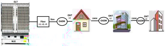
Figure 2.
The optical drop multiplexer for FTTH applications [24].
Although three disparate wavelengths (0.85, 1.20, and 1.45 μm) are employed in our simulations to stress-test the concept, the proposed PCF architecture is wavelength-scalable and can be directly re-targeted to the standard low-loss FTTH window (≈1.31–1.55 μm) by re-calibrating the extraction distances while preserving the geometry. The choice of 1.45 μm already lies close to the extended low-loss region of modern low-water-peak fibers.
The theoretical background of PCF light guidance and coupling is well established in the literature [1,4,5]. In this work, we focus on the numerical validation of the proposed design.
The innovation of the proposed structure lies in its compact PCF-based geometry (19 mm length), which achieves efficient wavelength-selective dropping by exploiting wavelength-dependent coupling lengths. In contrast to AWG or MMI-based multiplexers, our device requires no lithography, has inherently lower thermal sensitivity, and can be fabricated using the standard stack-and-draw method. This makes it a promising low-cost, compact, and scalable solution for PON and FTTH applications.
2. Materials and Methods
Air holes are evenly spaced throughout the cladding area surrounding a core defect zone to make photonic crystal fiber. To create lower-index areas, air holes are evenly spaced along the length of the fiber, with pure silica serving as the background material (Figure 3).
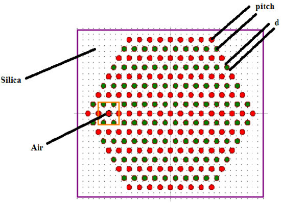
Figure 3.
Photonic crystal fiber structure.
The parameters of our structure are the radius (d), which indicates the dimension of the air holes; pitch (Λ), is the separation between two air holes; and z, the length of the fiber. Table 1 represents the parameter values.

Table 1.
The parameters of the PCF.
The selected values of radius (0.9 μm) and pitch (1.88 μm) are based on previously reported designs [2,3,12], where similar PCF geometries were successfully used for multiplexer applications. These values offer a balance between mode confinement, transmission efficiency, and feasible coupling lengths.
In that order, on three different planes: XZ (y = 0 mm), XY (z = 0 mm), and XY (z = 19 mm), Figure 4a–c shows the refractive index profile structure of the optical drop mux PCF design in its entirety. The background silica material in these figures is displayed in red, whereas the air-hole regions are emphasized in purple.
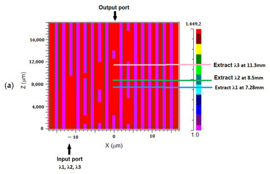
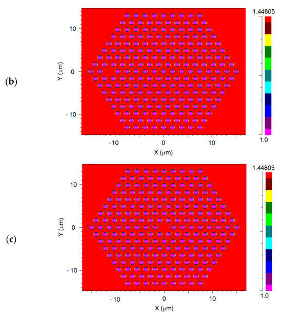
Figure 4.
Refractive index profile of the 1 × 3 drop multiplexer wavelength: (a) XZ plane at y = 0 mm. (b) XY Plane at z = 0 mm. (c) XY plane at z = 19 mm.
The main purposes of this device are to contain light inside the channel (core) and adjust the distance along which light couples to two nearby ports. Certain air-hole actors can be swapped out for pure silica high-index material throughout the fiber to produce these effects.
Since the MTIR (modified total internal reflection) is the foundation of our concept’s light-guiding mechanism, when two closer ports have the same index of refraction, light can be linked between them. Additionally, significant light confinement (pure silica) can be achieved by a port with a high index value. The three wavelengths are injected into the same core (input port), and at the output port, they are recovered independently at various distances.
2.1. Simulation Environment and Boundary Conditions
All numerical simulations were carried out using the COMSOL Multiphysics environment 6.2 for solving the Helmholtz wave equation in dielectric media. A triangular mesh with adaptive refinement was applied in the vicinity of the core and air-hole regions to ensure convergence, with a minimum element size of 0.02 µm and a maximum growth rate of 1.3. The silica background was modeled with a refractive index n = 1.45, and air holes were set to n = 1.0.
To avoid spurious reflections at the computational boundaries, perfectly matched layers (PMLs) were applied surrounding the cladding region, ensuring absorption of outgoing fields. The input optical field was launched as the fundamental mode at the designated input port, and modal decomposition was used at the output to quantify transmission efficiency. The propagation length was fixed at 19 mm, consistent with the designed extraction distances. These settings guarantee numerical stability and reproducibility of the reported results.
2.2. Fabrication Feasibility
Although this work is simulation-based, the proposed PCF structure can be fabricated using existing technologies. The most common approach is the stack-and-draw method, where silica capillaries are stacked to form the desired arrangement and then drawn into fiber. Extrusion and sol–gel methods have also been successfully applied to produce complex PCF geometries. Recent progress in preform stacking allows precise control of hole diameter and pitch, with tolerances typically below ±0.1 μm. Selective hole-filling and controlled pressurization during the draw process make it possible to realize alternating hole configurations as required by our design. Therefore, the proposed structure is within current fabrication capabilities, although practical challenges remain in achieving uniformity over long lengths. Experimental fabrication and validation of this PCF will be pursued in future work.
It is important to note that real-world fabrication may introduce tolerances on the order of ±5–10% in the air-hole radius or pitch. Such deviations may affect coupling lengths and transmission efficiency, leading to small shifts in extraction distances. However, these variations do not alter the underlying operating principle of the proposed device. A detailed tolerance analysis will be considered in future work to assess robustness against manufacturing imperfections.
2.3. Light Source Specifications
The input source was modeled as a continuous-wave (CW), monochromatic Gaussian beam launched into the fundamental mode of the central core. A normalized input power of 1 W was assumed, which allows reporting the transmission in relative terms. The three wavelengths used in this study were λ1 = 0.85 μm, λ2 = 1.20 μm, and λ3 = 1.45 μm. The polarization was fixed along the x-axis, and a negligible spectral linewidth was assumed, consistent with idealized CW laser excitation in optical communication systems.
2.4. Light-Propagation Mechanism in the Proposed PCF Multiplexer
This section provides a detailed explanation of the physical basis of light propagation within the proposed photonic crystal fiber (PCF)-based optical drop multiplexer.
2.4.1. Guidance Mechanism
The photonic crystal fiber (PCF) features a silica core surrounded by a periodic array of air holes that reduces the cladding’s effective index. Light is guided by modified total internal reflection (MTIR) because neff,core > neff,clad. In this regime, the transverse field satisfies the scalar Helmholtz eigenproblem for each wavelength λ, yielding the fundamental mode confined to the core.
2.4.2. Inter-Core Coupling
When two neighboring cores are brought into proximity by the hole pattern, their fundamental modes overlap and form even/odd supermodes with propagation constants β+ and β−. The coupling coefficient is κ = (β+ − β−)/2. Neglecting loss and phase mismatch, the power exchange between the excited core (1) and the adjacent core (2) follows:
P2(z) = P1(0) sin2(κz), P1(z) = P1(0) cos2(κz).
The distance for complete transfer in this ideal case is the coupling length Lc = π/(2κ). With a small phase mismatch Δβ, the exchanged power becomes the following:
P2(z) = [κ2/(κ2 + (Δβ/2)2)] · sin2(√(κ2 + (Δβ/2)2) · z).
2.4.3. Wavelength Selectivity
The coupling coefficient depends on wavelength through modal size and dispersion in the microstructured cladding; hence κ = κ(λ) and Lc = Lc(λ). The proposed geometry leverages this dependence: by modulating the air-hole positions along z, the inter-core spacing and overlap are locally adjusted to create coupling windows where a chosen wavelength attains z ≈ (2 m + 1)·Lc(λ)/2, enabling its drop into the side core. Other wavelengths, having different Lc, do not satisfy this condition at the same z and thus remain in the through path. This produces three distinct extraction distances within the total device length.
2.4.4. Loss and Isolation
The microstructured cladding maintains low confinement loss in the coupling sections, and isolation between channels is enforced by the mismatch of Lc across wavelengths and by short, uncoupled sections between coupling windows. In practice, small propagation loss α can be included as P(z) ≈ P(0) e−αz e−αz, which does not alter the wavelength-selective nature of the coupling but slightly reduces absolute transmitted power.
2.4.5. Scalability
Because κ is governed by normalized geometric parameters (e.g., d/Λ) and modal overlap, the same architecture can be retargeted to the standard FTTH band (≈1.31–1.55 μm) by recalibrating the extraction distances to the corresponding Lc(λ) without changing the core layout.
This mechanism explains the simulated behavior of the device: each designated wavelength is extracted at a specific distance where its coupling condition is met, while the others remain largely untransferred, yielding the observed wavelength-selective drop operation within a compact fiber length.
3. Results
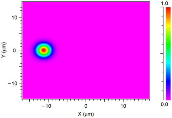
Figure 5.
The 1 × 3 input optical drop multiplexing of the three optical signals.
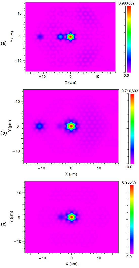
Figure 6.
The 1 × 3 output optical drop multiplexing of the three optical signals ((a) λ = 0.85 µm; (b) λ = 1.45 µm; (c) λ = 1.2 µm) at z = 7.280, 8.5, 11.3 mm, respectively.
Our input signals of 0.85, 1.45, and 1.2, were separated at the output port at different distances (z = 7280, 8500, and 11,300 µm, respectively) after a distance of 19 mm, suggesting that the optical drop multiplexer had an effect. For the input signals of 0.85, 1.45, and 1.2 µm, the transmission is 98%, 71%, and 90%, respectively.
For the chosen wavelength channels, Figure 7 shows how light propagates at the x-z plane over the entire fiber length and how light is coupled between cores.
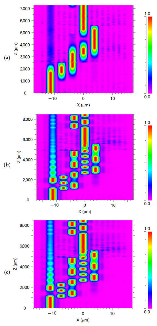
Figure 7.
Profile of intensity of the 1 × 3 wavelength optical drop multiplexer (a) λ = 0.85 µm; (b) λ = 1.45 µm; (c) λ = 1.2 µm at z = 7.280, 8.5 and 11.3 mm, respectively.
Starting at the start of the transmission (λ1 = 0.85 µm) and moving toward the center (the output), the optical path is depicted in Figure 7a, passing through the following stages: through connecting the two closed ports 1 and 2 to the output channel (port 4) at z = 2.3 mm; then, at z = 2.4 mm, the light is pointed from port 2 to port 3 on the output channel; at z = 4 mm, from port 3 to 4; then at 3.7, from port 4 to 5. Ultimately, light propagates the output channel within the core region at z = 5.4 mm, from port 5 to port 4. It is extracted at the distance of z = 7.280 mm. The same is true for the other two wavelengths (1.45 and 1.2 µm) of Figure 7b and 7c, which cross the same path (from port 1 to 4) with different stages to arrive at the output port and be extracted at different distances z (8.5 and 11.3 µm).
Figure 8a–c illustrates how the input power reaches its maximum in the core at a distance of 70%, 85%, and 78% before dropping to zero at 0.968 mm, 0.94 mm, and 0.913 mm. Instead of needing to go through several stages to go from one segment to its neighbor through light coupling, this enables the input power to be concentrated on the output port. At 2.527 mm, 2.459 mm, and 9.5 mm, the output port power starts to rise and reaches a maximum of 42%, 29%, and 39%.
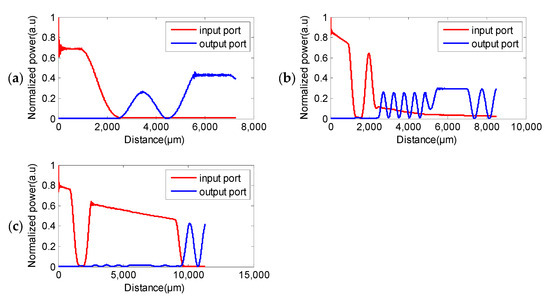
Figure 8.
The input and output power of the 1 × 3 wavelength optical drop multiplexer a for the optical signal (a) λ = 0.85 µm; (b) λ = 1.45 µm; (c) λ = 1.2 µm.
Figure 9 shows the output power for the 3 wavelengths 0.85, 1.45, and 1.2. As we can see, the wavelength 0.85 µm is extracted at the distance of Z1 = 7.280 mm when the other 2 wavelengths have zero power at this distance. The same is true for the other wavelengths, 1.45 and 1.2 µm, which are extracted at Z2 and Z3 when the others have zero power at these distances.
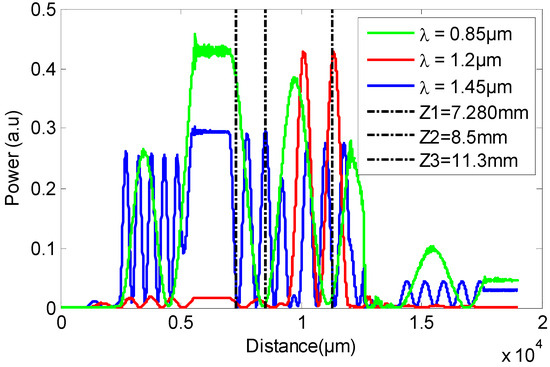
Figure 9.
Standardized output power of 1 × 3 power optical drop multiplexer for the optical signals λ1 = 0.85 µm, λ2 = 1.45 µm, and λ3 = 1.2 µm at different distances Z1, Z2, and Z3.
In the context of FTTH deployment, the proposed drop multiplexer is compatible with high-capacity passive optical networks such as GPON (2.5 Gbit/s), XG-PON (10 Gbit/s), and NG-PON2 (up to 40 Gbit/s), as the PCF geometry maintains stable coupling and low-loss operation over the relevant spectral range. While the present study focuses on wavelength-selective extraction, the structure’s wide operational bandwidth ensures that it does not represent a limiting factor for system data rates; the achievable rate will depend primarily on the source bandwidth and system dispersion compensation.
While this study employs a fixed PCF geometry based on previously optimized designs, future work will include a systematic sensitivity analysis of the structure parameters (d, Λ, z) to identify configurations that further minimize dispersion and maximize transmission efficiency over the FTTH wavelength window.
The simulation results obtained here are in line with the experimental performance trends reported in previous PCF-based multiplexers [2,3,11,12], particularly in terms of coupling length and low insertion loss. This consistency with prior experimental data reinforces the feasibility of our design for practical implementation. Future work will focus on fabricating and experimentally validating the proposed 1 × 3 drop multiplexer.
4. Conclusions
This work has proposed a 1 × 3 wavelength drop multiplexer and shown how to use it with integrated multiple air-hole placements in the PCF structure in order to achieve the required optical power outputs at their highest level. Along the PCF axis, pure silica will take the place of these air holes up until the output. This work also demonstrates how to use the MTIR mechanism of the multicore PCF to change the direction of light propagation. Hence, light can only couple to silica components, making the higher index material more effectively light-confined. The outcomes of the simulation indicated that the 0.85 µm, 1.45 µm, and 1.2 µm operating wavelengths, which are injected on the same input port, can be extracted on the same output port at different distances Z (7.28, 8.5, and 11.3 mm) after a propagation length of 19 mm. For FTTH deployment, the practical target wavelengths would be selected within the 1.31–1.55 μm band; the present results at 0.85, 1.20, and 1.45 μm serve as a proof-of-concept demonstrating the device’s wavelength selectivity and geometry-driven operation, which can be transferred to the telecom window.
The novelty of this work resides in demonstrating a compact PCF optical drop multiplexer designed specifically for PON applications. By exploiting wavelength-dependent coupling in a short-length PCF, the structure provides high transmission, distinct channel separation, and compatibility with conventional fiber fabrication techniques, offering an innovative alternative to AWG- and MMI-based multiplexers.
The results indicate favorable performance, showing that three wavelengths can pass through the device and be extracted based on the simulation results. Following a distance of 19 mm, transmission is 98%, 71%, and 90% for the output ports of 0.85, 1.45, and 1.2 µm wavelengths.
It should be noted that environmental parameters, such as temperature, may influence the performance of the proposed multiplexer through thermo-optic index changes and thermal expansion of the PCF structure. While this study was carried out under idealized conditions, future work will investigate temperature dependence and other environmental effects both numerically and experimentally.
The proposed structure does not aim to replace AWGs at this stage, but rather to introduce a compact, low-cost alternative that demonstrates favorable transmission and distinct wavelength selectivity. Future work will include a detailed comparison of crosstalk, polarization dependence, and dispersion with AWG- and MMI-based solutions to further assess practical viability.
Author Contributions
Conceptualization, M.D., M.C.E.O. and A.A.H.; methodology, M.D., M.C.E.O. and A.A.H.; software, M.D., M.C.E.O. and A.A.H.; validation, M.D., M.C.E.O. and A.A.H.; formal analysis, M.D., M.C.E.O. and A.A.H.; investigation, M.D., M.C.E.O. and A.A.H.; resources, M.D., M.C.E.O. and A.A.H.; data curation, M.D., M.C.E.O. and A.A.H.; writing—original draft preparation, M.D., M.C.E.O. and A.A.H.; writing—review and editing, M.D., M.C.E.O. and A.A.H.; visualization, M.D., M.C.E.O. and A.A.H.; supervision, M.D., M.C.E.O. and A.A.H.; project administration, M.D., M.C.E.O. and A.A.H.; funding acquisition, M.D., M.C.E.O. and A.A.H. All authors have read and agreed to the published version of the manuscript.
Funding
The authors declare that no funds, grants, or other support were received during the preparation of this manuscript.
Institutional Review Board Statement
Not applicable.
Informed Consent Statement
Not applicable.
Data Availability Statement
No data was used for the research described in the article.
Conflicts of Interest
The authors declare no conflict of interest.
References
- Knight, J.C.; Birks, T.A.; Russell, P.S.J.; de Sandro, J.P. Properties of photonic crystal fiber and the effective index model. J. Opt. Soc. Am. A 1998, 15, 748–752. [Google Scholar] [CrossRef]
- Harrat, A.A.; Debbal, M.; Ouadah, M.C.E. Numerical Analysis of 1 X 4 Photonic Crystal Fiber Multiplexer. Prog. Electromagn. Res. M 2023, 118, 127–136. [Google Scholar] [CrossRef]
- Harrat, A.A.; Debbal, M.; Ouadah, M.C.-E. 1 × 2 power splitter based on photonics crystals fibers. J. Opt. Commun. 2023, 44, 417–420. [Google Scholar] [CrossRef]
- Knight, J.; Arriaga, J.; Birks, T.; Ortigosa-Blanch, A.; Wadsworth, W.; Russell, P. Anomalous dispersion in photonic crystal fiber. IEEE Photon Technol. Lett. 2000, 12, 807–809. [Google Scholar] [CrossRef]
- Hougaard, K.G.; Bjarklev, A.; Knudsen, E.; Libori, S.B.; Riishede, J.; Skovgaard, P.M.; Broeng, J. Coupling to photonic crystal fibers. In Proceedings of the Optical Fiber Communication Conference, Anaheim, CA, USA, 17–22 March 2002; Optica Publishing Group: Washington, DC, USA, 2002; p. ThGG11. [Google Scholar]
- Wang, Y.; Qu, J.; Wang, L.; Qiu, C.; Yu, C. Photonic Crystal Fiber Metalens with Plasmonic Planar Chiral Units for Arbitrary Polarization Focusing. In Proceedings of the 2025 Optical Fiber Communications Conference and Exhibition (OFC), Los Angeles, CA, USA, 30 March–3 April 2025; IEEE: New York, NY, USA, 2025; pp. 1–3. [Google Scholar]
- Ehyaee, A.; Rahmati, A.; Bosaghzadeh, A.; Olyaee, S. Machine learning-enhanced surface plasmon resonance based photonic crystal fiber sensor. Opt. Express 2024, 32, 13369–13383. [Google Scholar] [CrossRef]
- Lin, P.; Li, Y.; Cheng, T.; Suzuki, T.; Ohishi, Y. Coexistence of photonic bandgap guidance and total internal reflection in photonic crystal fiber based on a high-index array with internal air holes. IEEE J. Sel. Top. Quantum Electron. 2015, 22, 265–270. [Google Scholar] [CrossRef]
- Tembo, S.R.; Vaton, S.; Courant, J.-L.; Gosselin, S. A tutorial on the EM algorithm for Bayesian networks: Application to self-diagnosis of GPON-FTTH networks. In Proceedings of the 2016 International Wireless Communications and Mobile Computing Conference (IWCMC), Paphos, Cyprus, 5–9 September 2016; IEEE: New York, NY, USA, 2016; pp. 369–376. [Google Scholar][Green Version]
- Erdogan, T. Optical add–drop multiplexer based on an asymmetric Bragg coupler. Opt. Commun. 1998, 157, 249–264. [Google Scholar] [CrossRef]
- Wang, Y.; Lv, H.; Jiang, T.; Zhang, K. Reconfigurable optical add-drop multiplexer at 1550 nm using magnetically-coupled switches based on a photonic crystal. Optik 2019, 192, 162878. [Google Scholar] [CrossRef]
- Harrat, A.A.; Debbal, M.; Ouadah, M.C.E. New proposal for a two-channel optical multiplexer based on photonic crystal fibers. Optik 2023, 295, 171491. [Google Scholar] [CrossRef]
- Kaur, R.; Kaur, D.; Kaur, R. An Overview on Network Topologies. Int. J. Mod. Dev. Eng. Sci. 2023, 2, 40–43. [Google Scholar]
- Mukherjee, B. WDM optical communication networks: Progress and challenges. IEEE J. Sel. Areas Commun. 2000, 18, 1810–1824. [Google Scholar] [CrossRef]
- Maleki, M.J.; Soroosh, M. An ultra-fast all-optical 2-to-1 digital multiplexer based on photonic crystal ring resonators. Opt. Quantum Electron. 2022, 54, 397. [Google Scholar] [CrossRef]
- Elyasi, B.; Javahernia, S. All optical digital multiplexer using nonlin-ear photonic crystal ring resonators. J. Optoelectron. Nanostruct. 2022, 7, 97–106. [Google Scholar]
- Maleki, M.J.; Soroosh, M. Design and simulation of a com-pact all-optical 2-to-1 digital multiplexer based on photonic crystal resonant cavity. Opt. Quantum Electron. 2022, 54, 818. [Google Scholar] [CrossRef]
- Rashed, A.N.Z. Optical add drop multiplexer (OADM) based on dense wavelength division multiplexing technology in next generation optical networks. Int. J. Multimed. Ubiquitous Eng. 2012, 7, 20–32. [Google Scholar] [CrossRef]
- Febriansyah, A.; Lammada, I. Perbaikan dan Pemeliharaan Jaringan Fiber to the Home (FTTH). Power Elektron. J. Orang Elektro 2022, 11, 116–122. [Google Scholar] [CrossRef]
- Yeh, C.H.; Wang, B.Y.; Hsu, W.H.; Liu, L.H.; Ko, H.S. A simple WDM-PON architecture together with private interconnected ONUs. IEEE Access 2021, 9, 126319–126323. [Google Scholar] [CrossRef]
- Asgarirad, M.; Jahromi, M.N. A taxonomy-based comparison of FTTH network implementation costs. Majlesi J. Electr. Eng. 2020, 14, 71–80. [Google Scholar]
- Abdellaoui, Z.; Dieudonne, Y.; Aleya, A. Design, implementation and evaluation of a Fiber To The Home (FTTH) access network based on a Giga Passive Optical Network GPON. Array 2021, 10, 100058. [Google Scholar] [CrossRef]
- Kramer, G.; Pesavento, G. Ethernet passive optical network (EPON): Building a next-generation optical access network. IEEE Commun. Mag. 2002, 40, 66–73. [Google Scholar] [CrossRef]
- Ab-Rahman, M.S.; Ehsan, A.A.; Shaari, A. Survivability in FTTH PON access network using optical cross add and drop multiplexer switch. J. Opt. Commun. 2006, 27, 263–269. [Google Scholar] [CrossRef]


Disclaimer/Publisher’s Note: The statements, opinions and data contained in all publications are solely those of the individual author(s) and contributor(s) and not of MDPI and/or the editor(s). MDPI and/or the editor(s) disclaim responsibility for any injury to people or property resulting from any ideas, methods, instructions or products referred to in the content. |
© 2026 by the authors. Licensee MDPI, Basel, Switzerland. This article is an open access article distributed under the terms and conditions of the Creative Commons Attribution (CC BY) license.