Abstract
Oxygen is a harmful substance in many processes because it can bring out corrosion and oxidation of food. This study aimed to enhance the removal of dissolved oxygen (DO) from water by employing a novel rotor–stator reactor (RSR). The effectiveness of the nitrogen stripping coupled with vacuum degassing technique for the removal of DO from water in the RSR was investigated. The deoxygenation efficiency (η) and the mass transfer coefficient (KLa) were determined under various operating conditions for the rotational speed, liquid volumetric flow rate, gas volumetric flow rate, and vacuum degree. The nitrogen stripping coupled with vacuum degassing technique achieved values for η and KLa of 97.34% and 0.0882 s−1, respectively, which are much higher than those achieved with the vacuum degassing technique alone (η = 89.95% and KLa = 0.0585 s−1). A correlation to predict the KLa was established and the predicted KLa values were in agreement with the experimental values, with deviations generally within 20%. The results indicate that RSR is a promising deaerator thanks to its intensification of gas–liquid contact.
1. Introduction
Oxygen plays a key role in the treatment of wastewater [1,2]. Nevertheless, oxygen is a harmful substance and removal of dissolved oxygen (DO) from water is an essential step carried out in power plants in order to prevent corrosion in boilers and pipes, improve heat transfer and enhance plant efficiency [3,4,5]. This operation is not only adopted in the power industry but is also necessary in the semiconductor, pharmaceutical, biotechnology and food industries, which also have stringent requirements for DO levels in water [6,7]. It is thus indispensable to remove DO from water prior to its use in many industries.
Various physical techniques, such as thermal degassing, vacuum degassing and nitrogen stripping, are currently employed by industries to remove DO from water. It has been reported that nitrogen stripping is the most effective approach for DO removal among these techniques [8]. Coupled techniques, such as thermal degassing with vacuum degassing or thermal degassing with nitrogen stripping, are also promising means for DO removal [8,9]. However, these techniques are conventionally carried out in packed towers/columns that exhibit poor mass transfer performance and, as a result, suffer limitations related to low efficiency, bulkiness, high costs and inflexibility in operation [10,11,12]. It is therefore necessary to develop a simple and efficient technique to remove DO from water, and a gas–liquid contactor capable of good mass transfer performance is desirable.
The rotor–stator reactor (RSR) is a novel multiphase contactor comprising a series of rotor rings and stator rings alternately configured in a radial direction [13]. In an RSR, a high-gravity environment several orders of magnitude greater than the Earth’s gravitational field can be created as a result of the huge centrifugal force produced by rapid rotation of the rotor. Consequently, the liquid stream in the RSR is broken into small elements and thin films [14,15,16]. There is also increased turbulence of the gas and liquid streams, in addition to rapid renewal of the gas–liquid interface [17,18]. All of these properties can greatly enhance the mass transfer rate in an RSR. Thus, RSRs have successfully been employed in degradation of organic pollutants [19,20], nanomaterial synthesis [21], CO2 capture [22] and other applications.
This work therefore employed an RSR to intensify the removal of DO from water through nitrogen stripping coupled with vacuum degassing (vacuum–N2–H2O–O2 system). The effects of various operating conditions, such as the rotational speed of the RSR, the liquid volumetric flow rate, the gas volumetric flow rate and the vacuum degree of the RSR, on the deoxygenation efficiency, as well as on the mass transfer coefficient, were investigated. Separate experiments involving nitrogen stripping (N2–H2O–O2 system) and vacuum degassing (vacuum–H2O–O2 system) were also carried out for comparison. Additionally, a correlation to predict the mass transfer coefficient (KLa) in the RSR was also established.
2. Materials and Methods
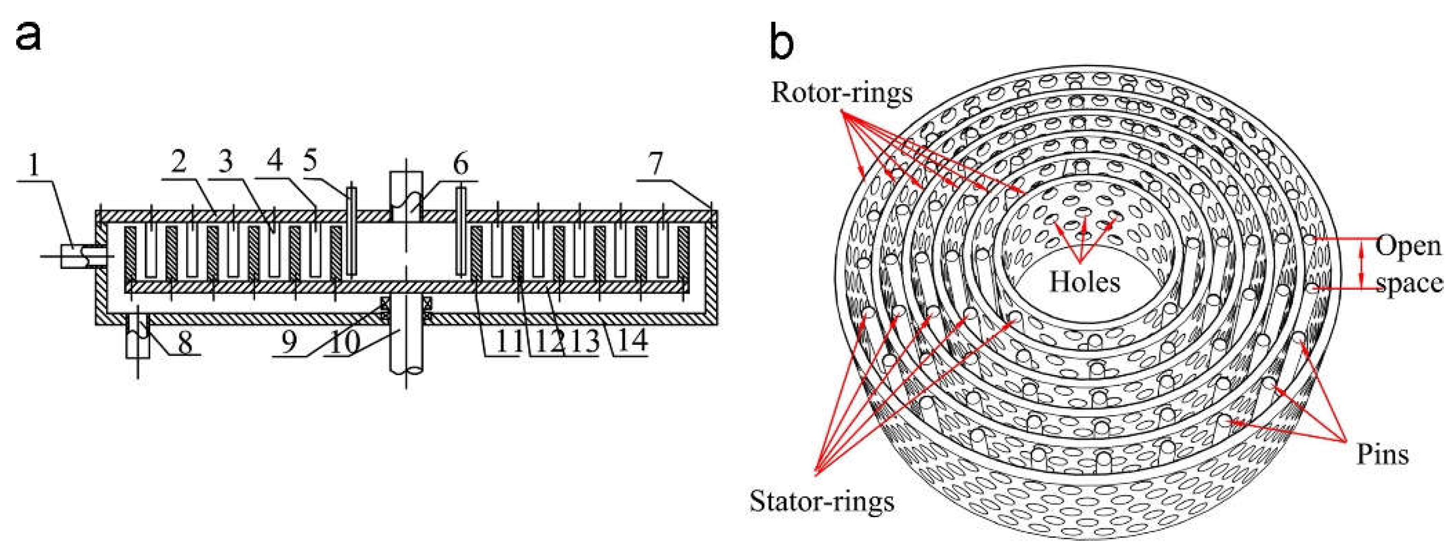
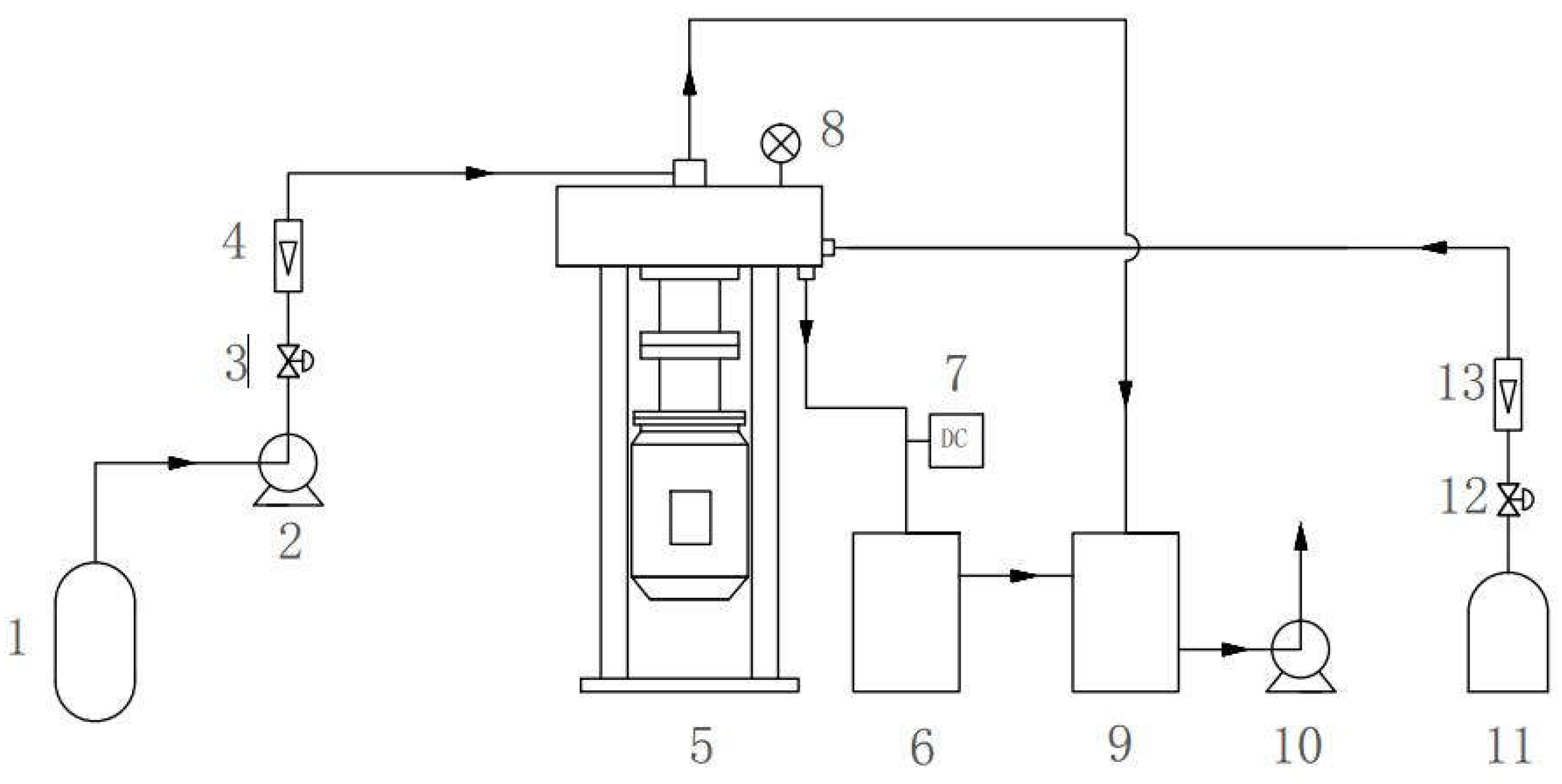
2.1. Structure of RSR
The structure of the RSR is shown in Figure 1a. The RSR consisted primarily of a liquid distributor, rotor seat, shaft, seal, rotor and stator. The rotor was comprised of six circular rings (named rotor rings) located on a rotor seat, which was connected to a motor by a shaft, while the stator consisted of five layers of pins (named stator rings) mounted concentrically on a cover cap. As shown in Figure 1b, the open space between pins in the same layer and the perforations in the rotor provide the flow channels for fluids in the RSR [15].
Figure 1.
Schematic diagrams of an RSR. (a) Structure of an RSR; (b) 3D diagram of rotor rings and stator rings: (1) gas inlet; (2) cover cap; (3) stator; (4, 7, 11) bolts; (5) liquid distributor; (6) gas outlet; (8) liquid outlet; (9) seal; (10) shaft; (12) rotor; (13) rotor seat; (14) casing.
As shown in Table 1, the inner diameter of the rotor rings ranged from 70 to 190 mm and thus could provide centrifugal acceleration ranging from 28.48 to 1395.68 m2/s. The stator rings (diameter ranges from 80 to 176 mm) allow the redistribution of liquid in an RSR.
Table 1.
Specifications of the RSR.
2.2. Experimental Procedure
Figure 2 shows the experimental setup for the vacuum–N2–H2O–O2 system. The liquid inlet and outlet of the RSR were connected to a centrifugal pump and sealed tank, respectively, whereas the gas inlet and outlet were connected respectively to a nitrogen gas cylinder and a vacuum system, which was made up of a vacuum pump and a buffer tank. The buffer tank helped to maintain the pressure balance in the DO removal system. Tap water was pumped via the liquid distributor into the RSR vacuumized below atmospheric pressure and allowed to flow radially outward through the rotor rings and stator rings, while nitrogen gas was introduced into the RSR via a gas inlet and allowed to flow inward through the rotor rings and stator rings. The nitrogen gas stream made contact in a counter-current with the water stream in the RSR, leading to removal of DO from the water by both vacuum degassing and nitrogen stripping. The gas and liquid streams finally exited the RSR via the gas and liquid outlets, respectively. The DO concentration in the tap water and deoxygenated water was measured using a DO detector (Rex, SJG-203A, CHN; detection limits: 0~19.99 mg/L). The composition of the gas used in this study was 99.5% N2 and 0.5% O2.
Figure 2.
Experimental set up: (1) Water tank; (2) centrifugal pump; (3, 12) valve; (4) liquid flow meter; (5) RSR; (6) sealed tank; (7) DO detector; (8) vacuum gauge; (9) buffer tank; (10) vacuum pump; (11) nitrogen cylinder; (13) gas flow meter.
Experiments involving nitrogen stripping or vacuum degassing were performed in the same way as with the vacuum–N2 technique.
The operating conditions were set as follows: rotational speed = 200–1400 rpm, liquid volumetric flow rate = 0.35–0.6 m3/h, gas volumetric flow rate = 1–7 m3/h, vacuum degree = 0.02–0.06 MPa, inlet liquid temperature = 300 ± 2 K (ambient temperature) and initial DO concentration in tap water = 7.85–8.01 mg/L.
2.3. Calculation of KLa and η
The equation for the experimental KLa (Equation (1)) was obtained by referring to literature [23]:
where xe is the equilibrium molar fraction of O2 in liquid which was obtained using Equation (2):
The deoxygenation efficiency (η) was determined by the molar concentration of O2 at the liquid inlet (cin) and the outlet (cout) (Equation (3)):
3. Results and Discussion
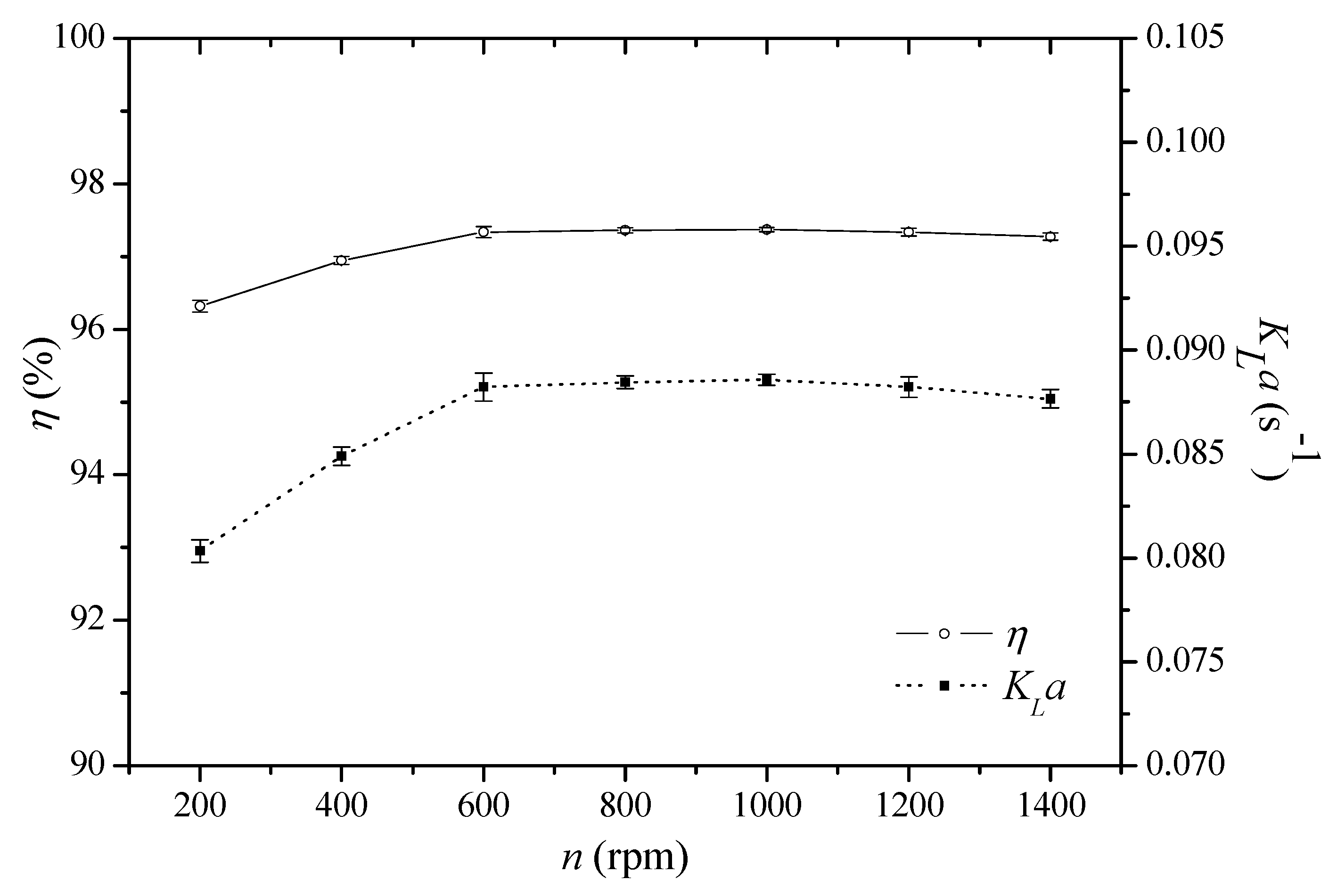
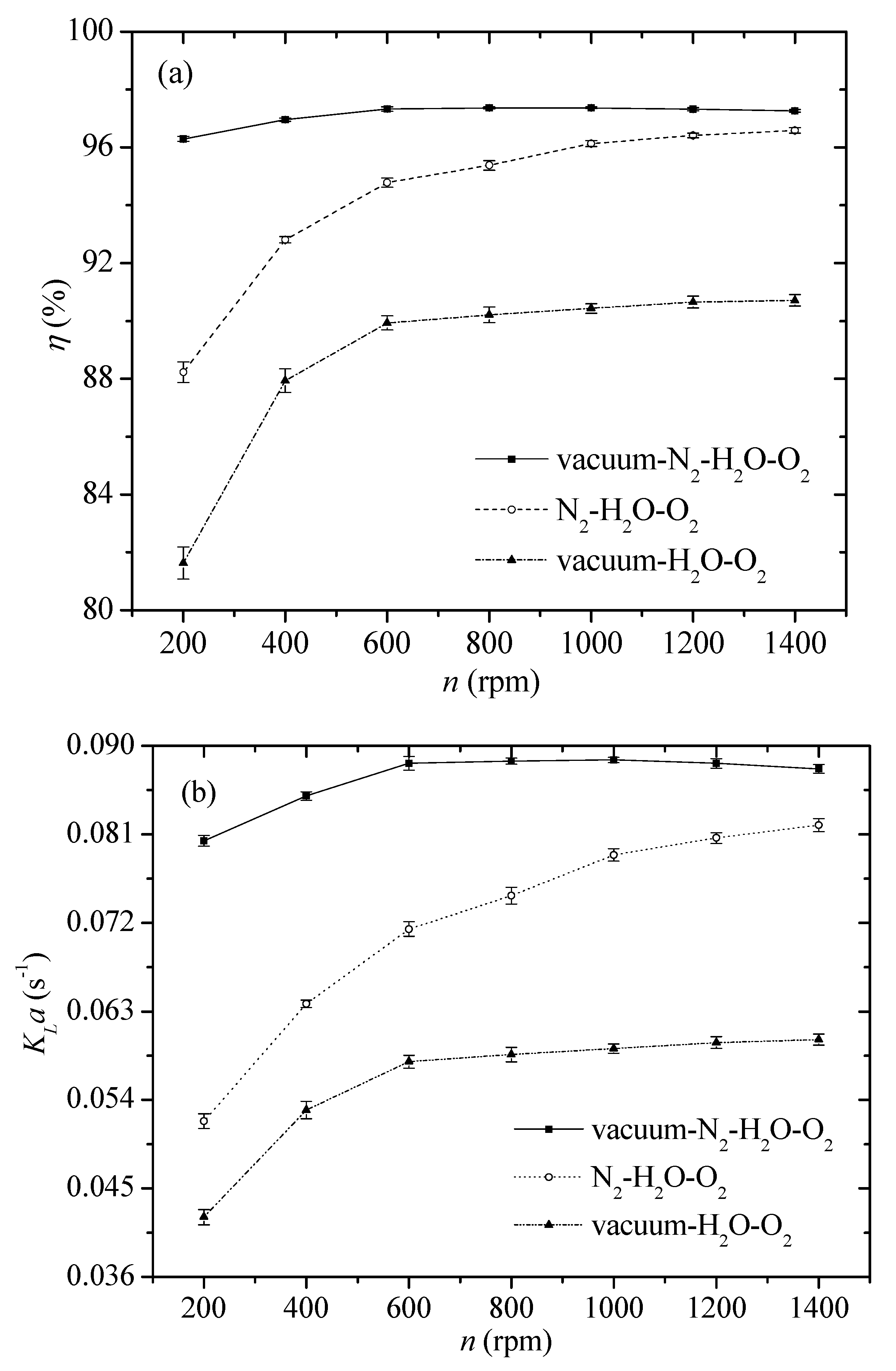
3.1. Effect of Rotational Speed
The effect of the rotational speed on η and KLa is illustrated in Figure 3. Both η and KLa increased from 96.32% and 0.0803 s−1 to 97.34% and 0.0882 s−1, respectively, with an increase in rotational speed from 200 to 600 rpm, beyond which both η and KLa showed little change with increasing rotational speed. Higher rotational speeds caused a larger centrifugal force, which split the liquid into finer elements and thinner films. Consequently, there was increased turbulence in the gas and liquid streams, a larger gas–liquid interfacial area and a faster renewal rate of the gas–liquid interface, resulting in thinner gas and liquid boundary layers. All of these factors led to an enhanced gas–liquid mass transfer rate and thereby a larger KLa and higher η.
Figure 3.
Effect of rotational speed on η and KLa (L = 0.4 m3/h; G = 3 m3/h; P = 0.06 MPa; initial DO concentration = 7.96 mg/L).
Nonetheless, increasing rotational speed brought about increased liquid velocity, which reduced liquid residence time in the RSR and liquid holdup declined accordingly, perhaps leading to a decrease in the gas–liquid interfacial area. The effect of the phenomena at rotational speeds greater than 600 rpm offset the aforementioned benefits of higher rotational speeds in this study, resulting in almost stable η and KLa.
According to Henry’s law, the lowest equilibrium oxygen concentration in liquid is 0.2028 mg/L at 25 °C. Thus, the highest deoxygenation efficiency is 97.47% for tap water with an initial DO concentration of 8.01 mg/L. The deoxygenation efficiency of 97.34% in this study was close to the highest one, suggesting the good deoxygenation effect of the RSR.
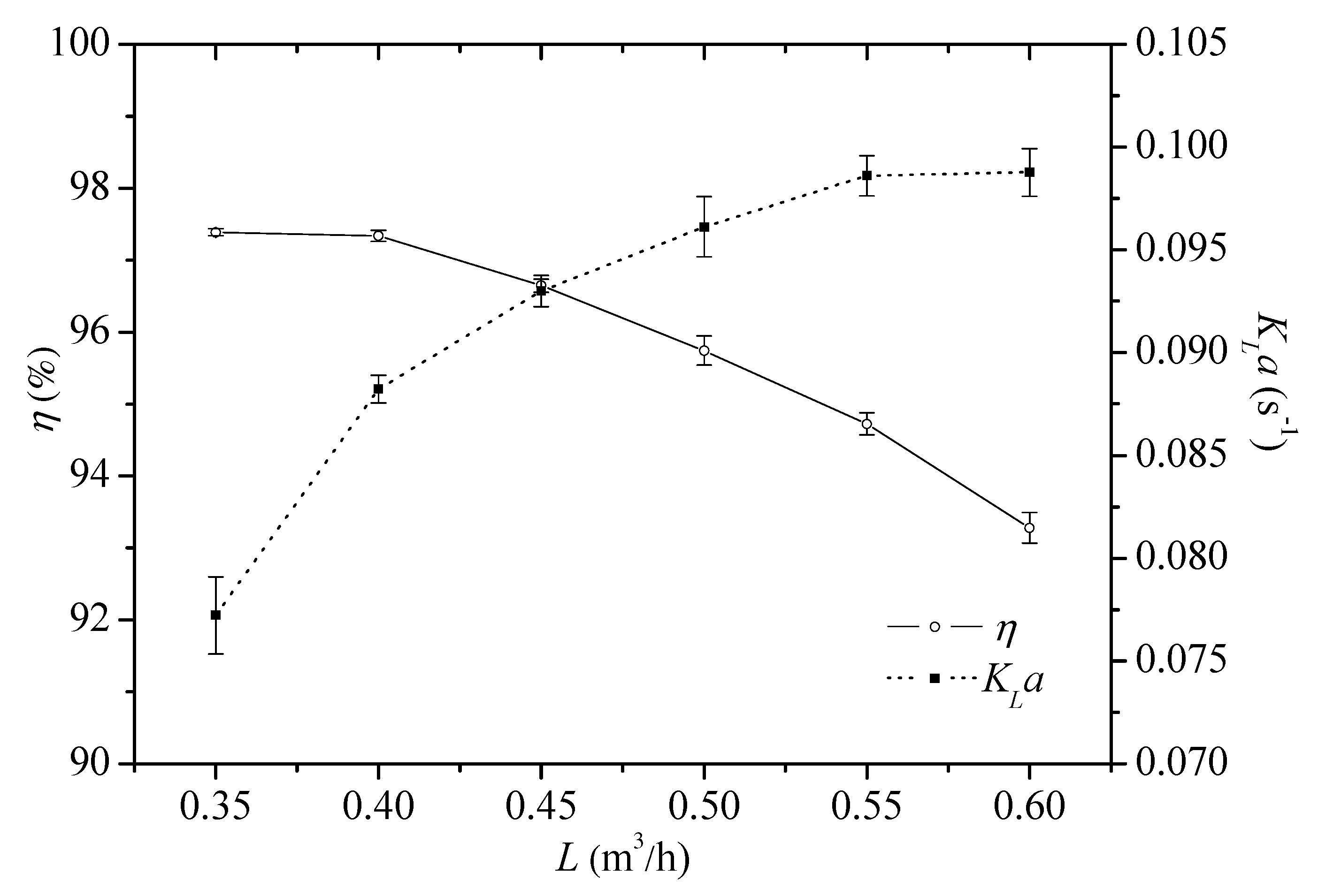
3.2. Effect of Liquid Volumetric Flow Rate
Figure 4 shows the effect of the liquid volumetric flow rate on η and KLa. It was noted that η decreased by 4.22% (from 97.39 to 93.28%) while KLa increased by 27.98% (from 0.0772 to 0.0988 s−1) with an increase in liquid volumetric flow rate from 0.35 to 0.6 m3/h. A higher liquid volumetric flow rate resulted in more liquid droplets and, consequently, a larger gas–liquid interface area, leading to an increase in KLa. Moreover, oxygen is sparingly soluble in water and the removal of DO from water is controlled by a liquid film. Thus, a higher liquid volumetric flow rate can result in a larger KLa. However, at a given gas–liquid equilibrium, vacuum degree and gas volumetric flow rate, a higher liquid volumetric flow rate led to a decline in η. A higher liquid volumetric flow rate led to a shorter liquid residence time in the RSR. This probably caused more liquid to exit the RSR before the maximum DO removal was achieved.
Figure 4.
Effect of liquid volumetric flow rate on η and KLa (n = 600 rpm; G = 3 m3/h; P = 0.06 MPa; initial DO concentration = 7.96 mg/L).
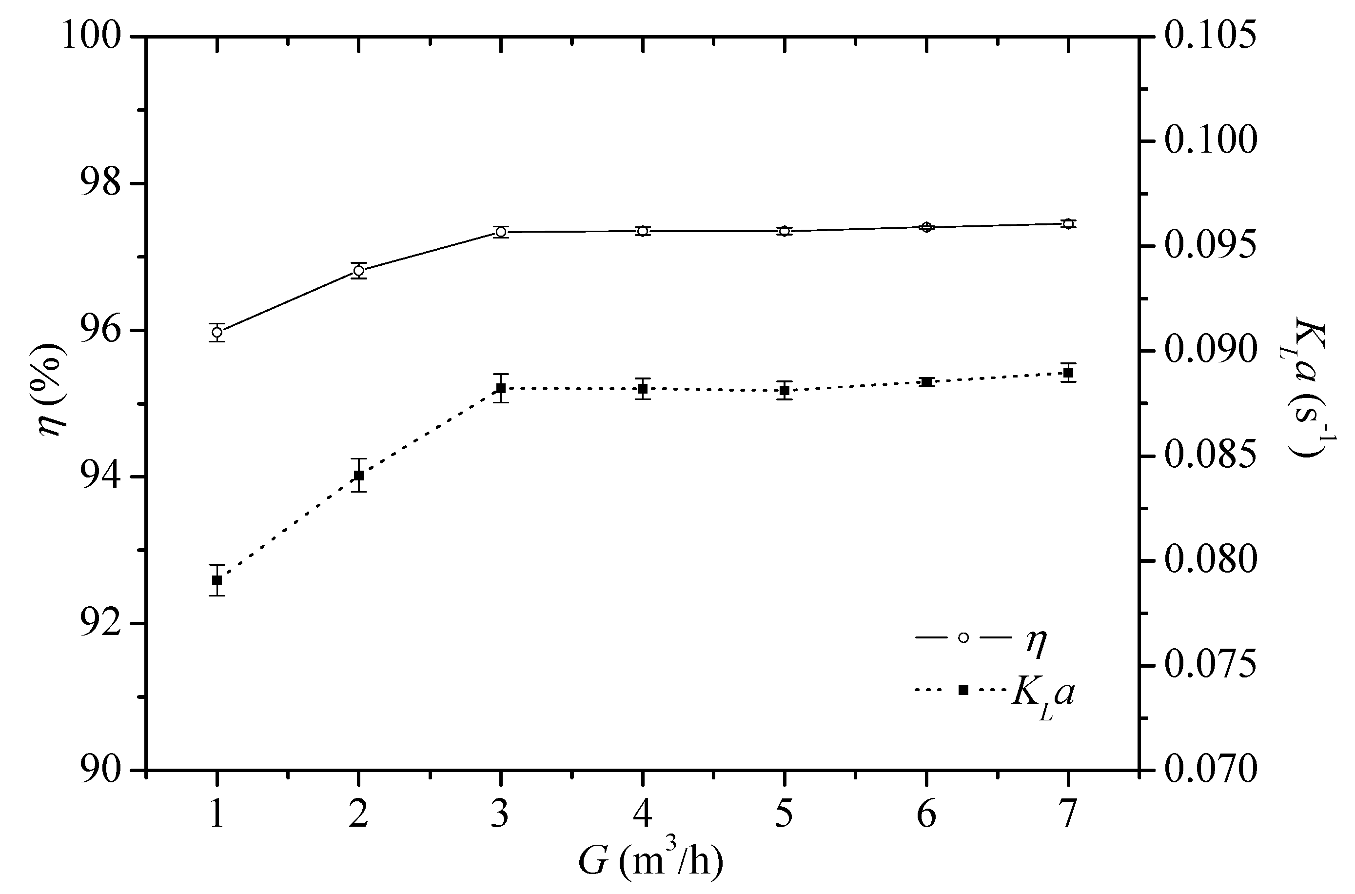
3.3. Effect of Gas Volumetric Flow Rate
As shown in Figure 5, both η and KLa increased from 95.97 to 97.34% and 0.0791 to 0.0882 s−1, respectively, with an increase in the gas volumetric flow rate from 1 to 3 m3/h, and thereafter they remained almost stable with further increases in the gas volumetric flow rate. This was because a higher gas volumetric flow rate resulted in increased turbulence in the gas and liquid streams, leading to a larger gas–liquid interfacial area and faster renewal rate of the gas–liquid interface, thereby resulting in the observed increase in η and KLa. However, as the gas volumetric flow rate further increased over 3 m3/h, the oxygen might have reached equilibrium between the gas and liquid phases. Thus, the increase in the gas–liquid interfacial area and the renewal rate of the gas–liquid interface had no effect on the oxygen transfer from water to gas. Therefore, both η and KLa remained stable when the gas volumetric flow exceeded 3 m3/h.
Figure 5.
Effect of gas volumetric flow rate on η and KLa (n = 600 rpm; L = 0.4 m3/h; P = 0.06 MPa; initial DO concentration = 7.96 mg/L).
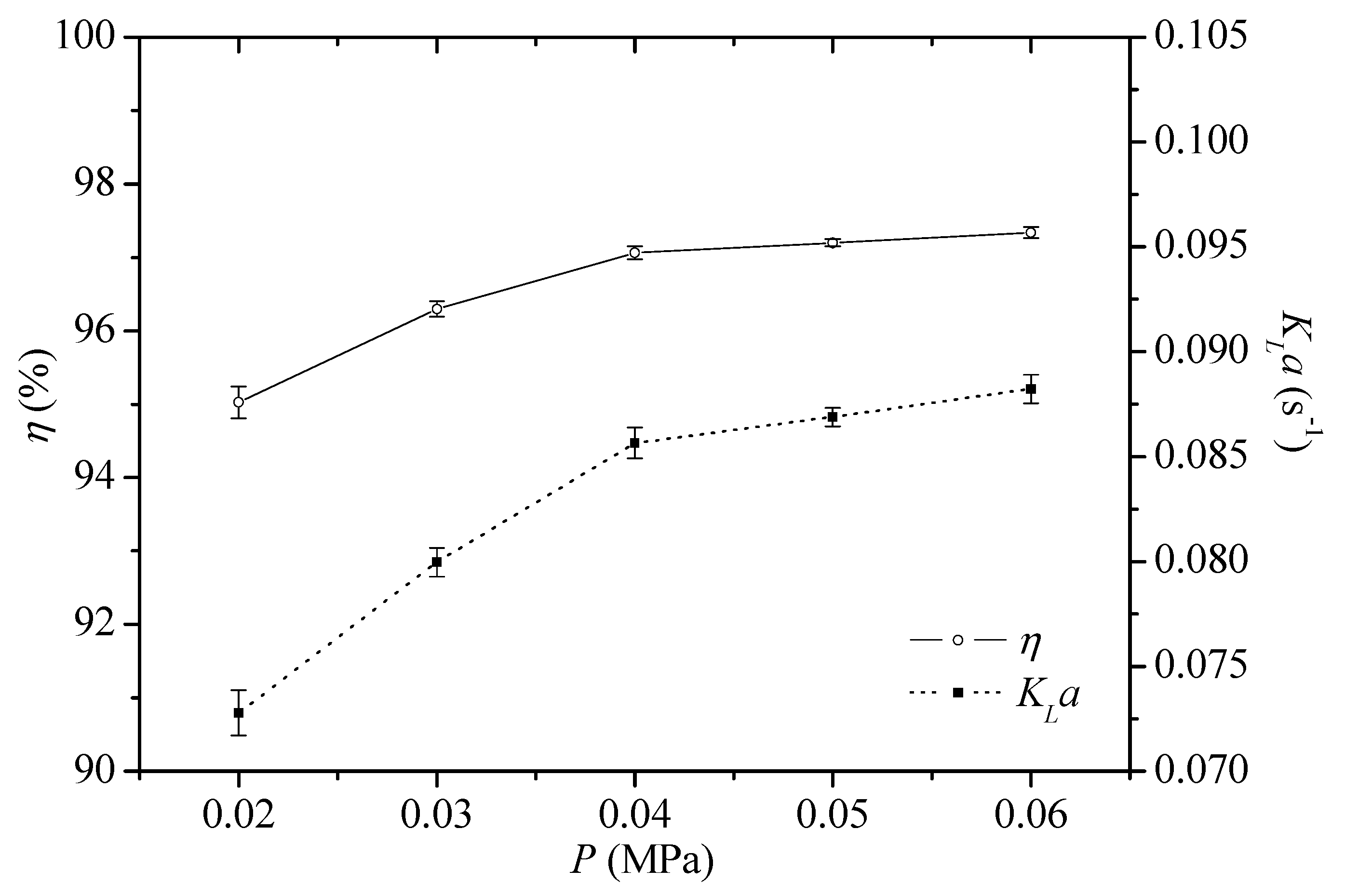
3.4. Effect of Vacuum Degree
The effect of the vacuum degree on η and KLa is shown in Figure 6. Both η and KLa increased from 95.03 to 97.06% and 0.0728 to 0.0856 s−1, respectively, when the vacuum degree rose from 0.02 MPa to 0.04 MPa. This was because a higher vacuum degree causes more water vapor and lower oxygen partial pressure in the gas phase. Therefore, a high vacuum degree and more water vapor in the gas phase resulted in an increased mass transfer driving force and, consequently, higher η. A higher vacuum degree also results in a thinner mass transfer boundary layer [24]. Consequently, there was reduced mass transfer resistance and, hence, KLa was larger, which is also conducive to oxygen removal from water.
Figure 6.
Effect of vacuum degree on η and KLa (n = 600 rpm; L = 0.4 m3/h; G = 3 m3/h; initial DO concentration = 7.96 mg/L).
However, the DO concentration was low and the mass transfer driving force was small when the vacuum reached a high degree. Furthermore, the oxygen approached equilibrium between the gas and liquid phases under such conditions. Hence, both η and KLa increased slowly from 97.06 to 97.34% and 0.0856 to 0.0882 s−1, respectively, with an increase in the vacuum degree from 0.04 to 0.06 MPa.
3.5. Comparison of Different Deoxygenation Systems in RSR
Figure 7 shows the values for η and KLa achieved by the N2–H2O–O2, vacuum–H2O–O2 and vacuum–N2–H2O–O2 systems in the RSR, respectively. It is evident that the vacuum–N2–H2O–O2 system achieved the highest values for KLa and η among the three systems. This can be attributed to the synergistic effect of nitrogen stripping and vacuum degassing, as oxygen partial pressure in the gas phase of the vacuum–N2–H2O–O2 system at a certain vacuum degree was lower than that of the N2–H2O–O2 system at atmospheric pressure or the vacuum–H2O–O2 system at the same vacuum degree. Thus, according to Henry’s law, the equilibrium concentration of DO in water in the vacuum–N2–H2O–O2 system was lower than that in the N2–H2O–O2 system at atmospheric pressure or the vacuum–H2O–O2 system at the same vacuum degree. In addition, it was also deduced that there was stronger turbulence in the vacuum–N2––H2O–O2 system in the RSR due to a faster gas velocity. This resulted in a larger gas–liquid interfacial area and a higher renewal rate of the gas–liquid interface, thereby leading to higher KLa and η.
Figure 7.
Comparison of the (a) η and (b) KLa of the N2–H2O–O2, vacuum–H2O–O2 and vacuum–N2–H2O–O2. L = 0.4 m3/h, G = 3 m3/h, P = 0.06 MPa and initial DO concentration = 7.96 mg/L in the vacuum–N2–H2O–O2 system; L = 0.4 m3/h, G = 3 m3/h and initial DO concentration = 7.85 mg/L in the N2–H2O–O2 system; and L = 0.4 m3/h, P = 0.06 MPa and initial DO concentration = 8.01 mg/L in the vacuum–H2O–O2 system).
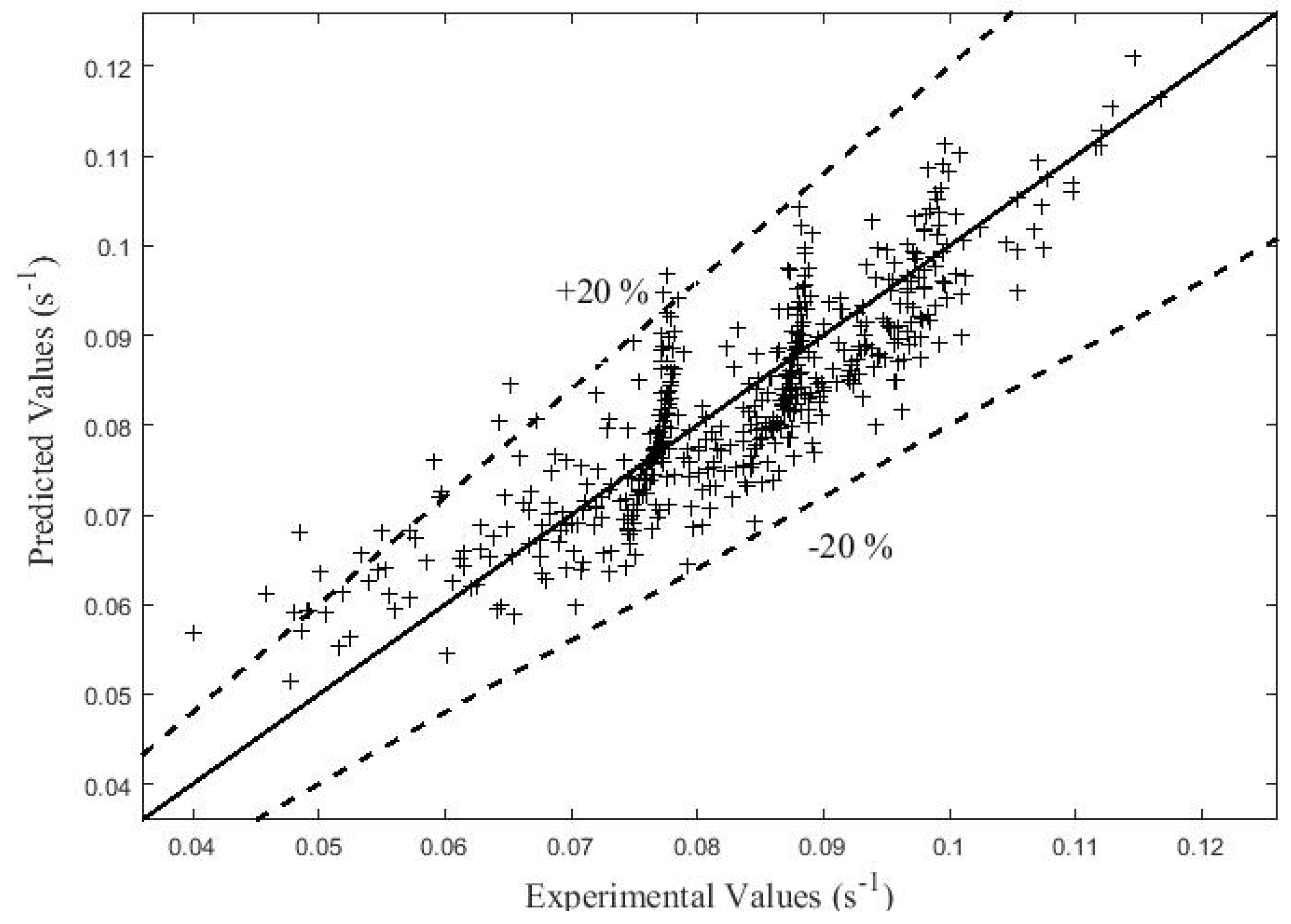
3.6. Correlation for KLa
It was assumed that the mass transfer coefficient KLa in the RSR was influenced by 14 major factors, as shown in Table 2. The values of these factors were based on the experimental conditions and physical properties of the gas and liquid.
Table 2.
Major influence factors of KLa.
The basic dimensions of the variables were [T], [L] and [M]. According to the Buckingham pi theorem [25], KLa can be expressed as follows (Equation (4)):
The coefficients of the correlation were obtained by fitting the experimental data to give the following equation (Equation (5)):
As shown in Figure 8, the predicted KLa values were in agreement with the experimental KLa values, with deviations generally within 20%. Thus, the correlation can be used to predict KLa in an RSR.
Figure 8.
Diagonal graph of experimental and predicted KLa values.
Table 3 shows that the accuracy of the correlation obtained in this study was similar to that of other studies in the literature. Furthermore, the correlation could predict KLa at atmospheric pressure as well as at reduced pressure.
Table 3.
Comparison of different deoxygenation systems in various high gravity devices.
4. Conclusions
This study employed a coupled vacuum–N2 technique to remove DO from water in an RSR. The effects of various operating conditions, including the rotational speed, the liquid volumetric flow rate, the gas volumetric flow rate and the vacuum degree, on the values of η and KLa were investigated. The optimum operating conditions in terms of deoxygenation efficiency and energy consumption were determined as a rotational speed of 600 rpm, a liquid volumetric flow rate of 0.4 m3/h, a gas volumetric flow rate of 3 m3/h and a vacuum degree of 0.06 MPa. Under these conditions, the vacuum–N2–H2O–O2 system achieved values for η and KLa of 97.34% and 0.0882 s−1, respectively. Additionally, a correlation to predict the KLa in the RSR was established, and the results show that the predicted values were in agreement with the experimental values, with deviations generally within 20%. These results indicate that the coupled technique carried out in an RSR is a feasible approach to remove DO from water under reasonable operating conditions thanks to the enhanced synergistic effect of nitrogen stripping and vacuum degassing under a high gravity environment.
Author Contributions
Conceptualization, L.S.; methodology, Z.Z.; validation, Z.L.; formal analysis, Y.X.; investigation, Z.Z.; writing—original draft preparation, Z.Z.; writing—review and editing, M.A.; supervision, L.S.; project administration, L.S.; funding acquisition, L.S. All authors have read and agreed to the published version of the manuscript.
Funding
This research was funded by the National Natural Science Foundation of China, grant number 22078009.
Data Availability Statement
Not applicable.
Acknowledgments
The authors gratefully acknowledge the financial support from the National Natural Science Foundation of China (No. 22078009).
Conflicts of Interest
The authors declare no conflict of interest.
Nomenclature
| cM | Total mole concentration of mixture, mol/L |
| cin | Molar concentration of O2 at the liquid inlet of RSR, mol/L |
| cout | Molar concentration of O2 at the liquid outlet of RSR, mol/L |
| DAB | Oxygen diffusivity in water, m2/s |
| EuL | Liquid Euler number, |
| FrL | Liquid Froude number, |
| G | Liquid volumetric flow rate, m3/h |
| g | Gravitational acceleration, m/s2 |
| H | Height of RSR, m |
| KLa | Overall volumetric mass transfer coefficient, s−1 |
| L | Liquid volumetric flow rate, m3/h |
| m | Phase equilibrium constant of oxygen |
| n | Rotational speed of RSR, rpm |
| P | Vacuum degree, MPa |
| QL | Liquid molar flow rate, mol/s |
| R | Radius of RSR, m |
| ReG | Gas Reynolds number, |
| ReL | Liquid Reynolds number, |
| ScG | Gas Schmidt number, |
| Sh | Sherwood number, |
| T | Temperature, °C |
| uG | Gas inlet velocity, m/s, |
| uL | Liquid inlet velocity, m/s, |
| x | Molar fraction of O2 in liquid |
| xe | Equilibrium molar fraction of O2 in liquid |
| xin | Molar fraction of O2 at the liquid inlet of RSR |
| xout | Molar fraction of O2 at the liquid outlet of RSR |
| α, β, γ, ε, θ, ξ | Fitting coefficients |
| σ | Liquid surface tension, kg/s2 |
| η | Deoxygenation efficiency, % |
| μG | Gas viscosity, kg/(m·s) |
| μL | Liquid viscosity, kg/(m·s) |
| ρG | Gas density, kg/m3 |
| ρL | Liquid density, kg/m3 |
| φ | Inlet air humidity, % |
| ω | Angular velocity of rotor, s−1 |
| [L] | Length dimension |
| [M] | Mass dimension |
| [T] | Time dimension |
| [Θ] | Temperature dimension |
References
- Caraman, S.; Luca, L.; Vasiliev, I.; Barbu, M. Optimal-Setpoint-Based Control Strategy of a Wastewater Treatment Process. Processes 2020, 8, 1203. [Google Scholar] [CrossRef]
- Kang, D.; Kim, K. Real Wastewater Treatment Using a Moving Bed and Wastewater-Borne Algal–2. Bacterial Consortia with a Short Hydraulic Retention Time. Processes 2021, 9, 116. [Google Scholar] [CrossRef]
- Abdi, A.; Karimi, A.; Razzaghi, M. Continuously deoxygenation of water in a reactor packed with glucose oxidase immobilized in MnO2/calcium alginate composite. J. Environ. Chem. Eng. 2016, 4, 2356–2361. [Google Scholar] [CrossRef]
- Lee, J.; Baek, S.M.; Boo, C.; Son, A.; Jung, H.; Park, S.S.; Hong, S.W. Water deoxygenation using a hollow fiber membrane contactor to prevent pipe corrosion for sustainable management of district heating systems: A pilot-scale study. J. Clean. Prod. 2020, 277, 124049. [Google Scholar] [CrossRef]
- Liang, M.; Yuan, J.; Li, L.; Lai, Z.; Sun, X.; Zhang, H. The preparation of a catalyst doped with Cu and Al on MCM-41 and its catalytic reduction removal of dissolved oxygen in reclaimed water at low temperatures. New J. Chem. 2021, 45, 11336. [Google Scholar] [CrossRef]
- Zekos, I.; Stack, M.M. A note on a design protocol for deoxygenation of water. Electrochem. Commun. 2019, 103, 12–16. [Google Scholar] [CrossRef]
- Jokar, S.; Aghel, B.; Fathi, S.; Karimi, M. Removal of dissolved oxygen from industrial raw water in a microchannel. Environ. Technol. Innov. 2021, 23, 101672. [Google Scholar] [CrossRef]
- Butler, I.B.; Schoonen, M.A.A.; Rickard, D.T. Removal of dissolved oxygen from water: A comparison of four common techniques. Talanta 1997, 41, 211–215. [Google Scholar] [CrossRef]
- Stucki, J.W.; Golden, D.C.; Roth, C.B. Preparation and Handling of Dithionite-Reduced Smectite Suspensions. Clays Clay Miner. 1984, 32, 191–197. [Google Scholar] [CrossRef]
- Mahdizadeh, F.; Eskandarian, M. Glucose oxidase and catalase co-immobilization on biosynthesized nanoporous SiO2 for removal of dissolved oxygen in water: Corrosion controlling of boilers. J. Ind. Eng. Chem. 2014, 20, 2378–2383. [Google Scholar] [CrossRef]
- Moon, J.S.; Park, K.K.; Kim, J.H.; Seo, G. Reductive removal of dissolved oxygen in water by hydrazine over cobalt oxide catalyst supported on activated carbon fiber. Appl. Catal. A-Gen. 2000, 201, 81–89. [Google Scholar] [CrossRef]
- Tan, X.; Li, K. Investigation of novel membrane reactors for removal of dissolved oxygen from water. Chem. Eng. Sci. 2000, 55, 1213–1224. [Google Scholar] [CrossRef]
- Song, Y.H.; Chu, G.W.; Chen, J.M.; Chen, J.F. A Rotor-Stator Reactor and Its Application. Chinese Patent 200410042631.6, 20 December 2006. (In Chinese). [Google Scholar]
- Chu, G.W.; Song, Y.H.; Yang, H.J.; Chen, J.M.; Chen, H.; Chen, J.F. Micromixing efficiency of a novel rotor–stator reactor. Chem. Eng. J. 2007, 128, 191–196. [Google Scholar] [CrossRef]
- Li, Y.; Wang, S.; Sun, B.; Arowo, M.; Zou, H.; Chen, J.; Shao, L. Visual study of liquid flow in a rotor-stator reactor. Chem. Eng. Sci. 2015, 134, 521–530. [Google Scholar] [CrossRef]
- Zhao, Z.; Sun, B.; Arowo, M.; Chu, G.; Chen, J.; Shao, L. Study on the hydrodynamic characteristics of a rotor-stator reactor by electrical conductance and response time technique. Chem. Eng. Process. 2016, 109, 158–163. [Google Scholar] [CrossRef]
- Zhao, Z.; Wang, J.; Sun, B.; Arowo, M.; Shao, L. Mass transfer study of water deoxygenation in a rotor–stator reactor based on principal component regression method. Chem. Eng. Res. Des. 2018, 132, 677–685. [Google Scholar] [CrossRef]
- Li, Y.; Si, J.; Arowo, M.; Liu, Z.; Sun, B.; Song, Y.; Chu, G.; Shao, L. Experimental investigation of effective gas-liquid specific interfacial area in a rotor-stator reactor. Chem. Eng. Process. 2020, 148, 107801. [Google Scholar] [CrossRef]
- Arowo, M.; Zhao, Z.; Li, G.; Chu, G.; Sun, B.; Shao, L. Ozonation of o-phenylenediamine in the presence of hydrogen peroxide by high gravity technology. Chin. J. Chem. Eng. 2018, 26, 601–607. [Google Scholar] [CrossRef]
- Zhao, Z.; Wang, L.; Fan, J.; Song, Y.; Chu, G.; Shao, L. Degradation of indigo carmine by coupling Fe(II)-activated sodium persulfate and ozone in a rotor-stator reactor. Chem. Eng. Process. 2020, 148, 107791. [Google Scholar] [CrossRef]
- Liu, C.; Li, Y.; Zhang, Y.; Zeng, X.; Chen, J.; Shao, L. Synthesis of Ni-CeO2 nanocatalyst by the microemulsion-gas method in a rotor-stator reactor. Chem. Eng. Process. 2018, 130, 93–100. [Google Scholar] [CrossRef]
- Feng, Q.; Wang, Y.; Wang, L.; Zhao, W.; Arowo, M.; Shao, L. CO2 absorption into K2CO3/KHCO3 solution enhanced by organic phase in a rotor-stator reactor. Sep. Sci. Technol. 2020, 55, 1239–1248. [Google Scholar] [CrossRef]
- Zhao, Z.; Zhang, X.; Li, G.; Chu, G.; Sun, B.; Zou, H.; Arowo, M.; Shao, L. Mass transfer characteristics in a rotor-stator reactor. Chem. Eng. Technol. 2017, 40, 1078–1083. [Google Scholar] [CrossRef]
- Zhang, D.; Liu, Y.; Xie, W. Preparation of γ-alumina ultrafiltration membrane by Sol–Gel process modified with polyvinyl alcohol. Membr. Sci. Technol. 2007, 27, 7–10. (In Chinese) [Google Scholar]
- Bansal, S.; Roy, S.; Larachi, F. Support vector regression models for trickle bed reactors. Chem. Eng. J. 2012, 207–208, 822–831. [Google Scholar] [CrossRef]
- Lin, H.; Song, Y.; Chu, G.; Chen, J. Experimental Investigation on Gas-Liquid Mass Transfer Characteristics of Rotor-Stator Reactor. J. Chem. Eng. Chin. Univ. 2007, 5, 882–886. (In Chinese) [Google Scholar]
- Guan, W. Study on Vacuum Deaeration Process in Rotating Packed Bed. Master’s Thesis, Beijing University of Chemical Technology, Beijing, China, 2014. (In Chinese). [Google Scholar]
Publisher’s Note: MDPI stays neutral with regard to jurisdictional claims in published maps and institutional affiliations. |
© 2021 by the authors. Licensee MDPI, Basel, Switzerland. This article is an open access article distributed under the terms and conditions of the Creative Commons Attribution (CC BY) license (https://creativecommons.org/licenses/by/4.0/).