Abstract
In this study, the pressure drop and heat transfer characteristics of smooth tube and internal helically micro-finned tubes with two different fin-to-fin height ratios i.e., equal fin height and alternating fin height, are computationally analysed. The tube with alternating fin height is analysed for proof of concept of pressure drop reduction. A single phase steady turbulent flow model is used with a Reynolds number ranging from 12,000 to 54,000. Water is used as working fluid with inlet temperature of 55 °C and constant wall temperature of 20 °C is applied. Friction factor, heat transfer coefficient, Nusselt number, and Thermal Performance Index are evaluated and analysed. The numerical results are validated by comparison with the experimental and numerical data from literature. The results showed that the thermal performance is enhanced due to helically finned tube for a range of Reynolds numbers, but at the expense of increased pressure drop as compared to a smooth tube. The helically finned tube with alternating fin heights showed a 5% decrease in friction factor and <1% decrease in heat transfer coefficient when compared with the equal fin heights tube, making it a suitable choice for heat transfer applications.
1. Introduction
Heat transfer enhancement techniques for heat exchanger applications can result in size reduction, high heat transfer coefficient, and lower operating cost. The increase in enhanced heat transfer can reach up to six times as compared to the unenhanced one [1]. A variety of heat transfer enhancement techniques are being used extensively in heat exchanger applications. There are two main types of heat transfer enhancement techniques: active and passive. Active methods require external energy input in addition to the pumping power required. Active methods are not so common in applications because of extra energy requirements. Passive methods require no additional energy and are built in to the system as its integral part. Passive methods increase the heat transfer by introducing turbulence and/or increase in surface area [2].
The drawback of these enhancement techniques is the increase in frictional losses due to turbulence and area increase. This requires a trade-off between the desired heat transfer enhancement and pumping power required. Because of higher frictional losses due to pressure drop, extensive research has been done and still going to find passive methods, which will reduce pressure drop as much as possible while increasing the heat transfer as much as possible [3]. Table 1 provides a summary of literature review of passive heat transfer enhancement techniques.

Table 1.
Literature review of passive heat transfer enhancement techniques.
Every passive method for enhancing the heat transfer has limitations because of the increased pressure drop. The selection of enhancement method is based upon the application and operational requirements. A lot of research is being done to develop passive techniques to reduce the thermal and hydraulic loses as much as possible. Among the variety of methods, micro-finned tubes are widely used in many heat transfer applications because of their relatively low pressure drop, stable performance, and low production cost [1]. The current study mainly focuses on the application of internal micro-finned tubes for the enhancement of heat transfer. Two types of micro fin geometries have been used i.e., equal fin-to-fin height and alternating fin-to-fin height with height ratios of 1:1 and 1:2, respectively. The alternating fin height is being introduced to study its effect on the reduction of pressure drop while keeping the heat transfer coefficient relatively the same as compared with the equal fin height. The geometrical parameters of the studied tube are taken from the experimental investigation of micro-finned tubes by [24]. The experimental setup consisted of a shell and tube counterflow heat exchanger. The tube had both internal and external micro fins with different fin parameters. Cold fluid flowed through the shell and hot fluid through the tube. We only chose the tube side fluid domain with only internal micro fins and constant wall temperature at outside of the tube. This was done to validate the numerical results with the work of [25], because they used the same fluid domain and boundary conditions in their computational fluid dynamic analysis. Numerical simulations were performed using ANSYS Fluent to calculate the heat transfer coefficient and pressure drop for different flow rates. The results were compared for both tube geometries to determine their relative thermal and hydraulic performance.
2. Methodology
The thermal and hydraulic flow characteristics of helically finned tubes are investigated numerically using ANSYS Fluent. The software uses the Navier–Stokes equation for with control volume method to numerically calculate the flow variables across the whole grid. Steady, three-dimensional turbulence flow and heat transfer characteristics for helically finned tubes and smooth tube are numerically calculated in this work. For turbulence, the Realizable k-ε model is used due to its accuracy, economy, and popularity for turbulent flow problems that are related to micro-finned tubes. It is also considered to be relatively accurate and robust when compared to standard model for the numerical flow of helically finned tubes [25].
2.1. Domain Definition
The geometrical specifications of the studied tubes are presented in Table 2. Figure 1 shows the 3D geometry along with cross- section of the finned tube and fin.
Table 2.
Geometric parameters of studied tubes.
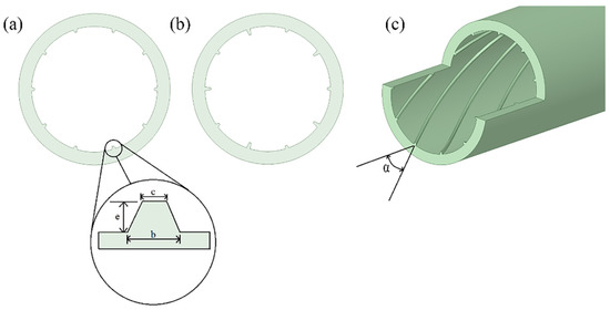
Figure 1.
Helically finned tube geometry (a); Equal fin height tube cross-section (b); Alternating fin height tube cross-section (c); and, 3D tube geometry.
The geometry of micro finned tubes is helically symmetric, which means that the whole domain is not needed for numerical computation. For this reason, a helically symmetric sector of the tube is used as the fluid domain for reduction in grid size and computational time. The smooth tube is modelled considering the full domain. Figure 2 shows the CAD model of fluid domain and tube sector cross-section.
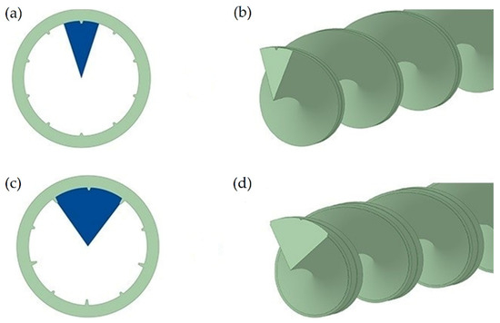
Figure 2.
Fluid domain CAD model and sector cross-section geometry (a); Equal fin height sector (b); Equal fin height fluid domain (c) Alternating fin height sector; and, (d) Alternating fin height fluid domain.
2.2. Meshing and Boundary Conditions
The meshing of the model was done using sweep meshing algorithm with local mesh controls on the edges. The mesh was kept fine at the fin edges, because this is the critical area where rapid changes in the flow will occur. Rotational periodic boundary condition is applied at the angled sides of the fluid domain. Water with uniform velocity and temperature of 55 °C enters the tube and a constant wall temperature of 20 °C is applied as a boundary condition to the wall of the tube. Figure 3 shows the mesh grid of smooth and helically finned tubes. The number of grid cells used for smooth, equal fin height, and alternating fin height tubes were approximately 600,000, 1,600,000, and 2,800,000, respectively.
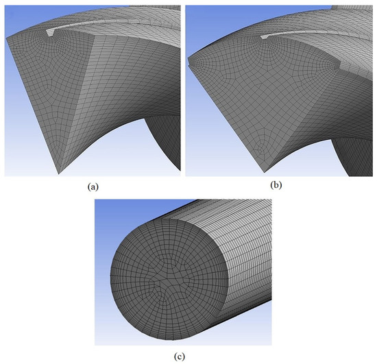
Figure 3.
Mesh grid of fluid domain sector (a); Equal fin height; (b) Alternating fin height; and, (c) Smooth tube.
2.3. Solution
The coupled solution algorithm is chosen, because it provides accurate results for turbulent single-phase steady-state flows. Therefore, because all of the governing equations are solved simultaneously in this method, the convergence rate is faster as compared to pressure-based segregated algorithm, but at the expanse of the computational cost.
Fanning friction factor, heat transfer coefficient, Nusselt number, and thermal performance index were calculated using the formulas from [15]
The fanning friction factor is calculated from the pressure field generated by the numerical solver.
Equation (2) calculates the overall heat transfer coefficient using the average values of temperature at the inlet and outlet of the fluid domain.
Equation (3) is used to calculate the Nu and Thermal Performance Index, which determines the overall thermohydraulic performance of the system.
The numerical error in the solution is computed using the discretization of grid as the main parameter. Three different grids are chosen with each fine grid double in size. After computing the solutions for each grid, Richardson extrapolation method Equation (4), is used to calculate the order of rate of convergence and Equation (5) is used to calculate the numerical error. The error represents the numerical accuracy of the simulation i.e., how accurate the solution is as compared with exact solution of mathematical model.
Here, P = order of convergence rate, ff = fine mesh, fc = coarse mesh, fm = medium mesh and r = grid spacing ratio. These numerical errors are represented as error bars in the figures.
3. Results and Discussion
Passive cooling techniques provide an overall good solution for improving thermohydraulic performance of heat exchangers. These techniques make use of both the surface area increase and flow disturbance for heat transfer enhancement. Normally micro-finned tubes with equal fin heights are common in heat exchanger applications. In this study, helical micro-finned tubes with same and alternating fin heights are numerically investigated to analyse the comparative thermohydraulic performance.
3.1. Grid Independence Study
A grid independence study was carried out to analyse the variation of friction factor and heat transfer coefficient with increasing grid size. Three grid sizes were chosen for both the micro-finned tubes. The plots presented in Figure 4 show no significant improvement in flow characteristics with increasing grid size. Therefore, the grid size of 1,600,000 and 2,800,000 elements were chosen for equal fin height tube and alternating fin height tube, respectively.

Figure 4.
Grid size dependence of (a) friction factor; (b) heat transfer coefficient, with respect to the number of grid cells.
3.2. Numerical Procedure Validation
The results that were obtained from numerical simulations for the studied tubes were compared with the experimental results from [24] and numerical results from [25]. The experimental setup consisted of eight different micro-finned tubes and a smooth tube with pressure drop and heat transfer measurements for a range of Reynolds numbers. In the current study, only one of micro-finned tube and smooth tube from experimental study were chosen for numerical simulation. Figure 5 shows a comparison of friction factor and Nu between current study and experimental results.
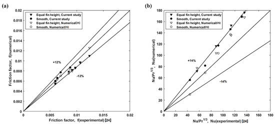
Figure 5.
Validation of results with experimental and numerical data from literature, (a) friction factor; (b) Scaled Nu,
The friction factor that is obtained from the numerical results shows good agreement with the experimental and numerical results for both the smooth and micro-finned tube. The numerical results remain within ±12% of the experimental results validating the numerical procedure. The scaled Nu deviates around ±14% from the experimental results and it also shows a good agreement with the numerical results that were performed by [25] using the same micro-finned tube geometry and boundary conditions. The current study scaled Nu overpredicts the experimental result by 14% due to the simplified fluid domain selection and constant temperature wall boundary condition as compared to the experimental setup. However, the results consistently capture the trend across the whole range of Re and even show better consistency than the numerical result from literature. This validates the model and solution method selected for the current geometry. This deviation is due to the simplified fluid domain and boundary conditions selection.
3.3. Effect of Micro Fins on Pressure Drop and Heat Transfer
The inclusion of micro fins in tube flow increases the heat transfer by introducing flow disturbances e.g., rotations and turbulence. However, this also increases the resistance to flow causing more pressure drop. The goal is to increase the heat transfer while keeping the pressure drop under acceptable levels. For carrying out the comparative analysis of pressure drop and heat transfer characteristics of the micro-finned tubes, numerical simulations were performed for Re ranging from 12,000 to 54,000. All of the simulations were performed under steady state using turbulence modelling. Figure 6 provides the temperature contours at the outlet cross-section for Reynolds number 12,000 and 54,000.
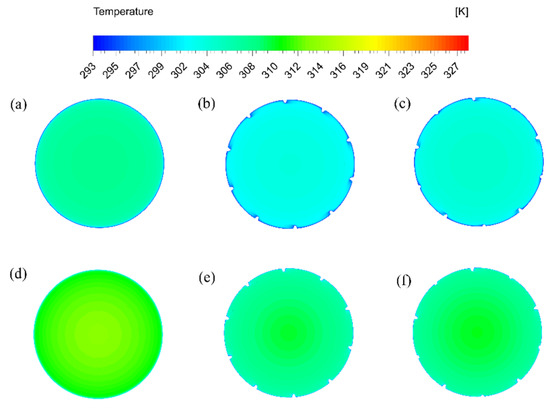
Figure 6.
Temperature contours at outlet cross-section (a) Smooth tube, Re 12,000; (b) Fin-to-Fin height 1:1, Re 12,000; (c) Fin-to-Fin height 1:2, Re 12,000; (d) Smooth tube, Re 54,000; (e) Fin-to-Fin height 1:1, Re 54,000; and, (f) Fin-to-Fin height 1:2, Re 54,000.
The temperature contour plots show that, as the Re number increases, the temperature drop becomes less and less, which agrees with the theory. The finned tubes have higher temperature drop as compared to smooth tube. Both of the helically finned tubes show relatively similar temperature drop at the outlet as the Re increases. This shows that the finned tube with fin-to-fin height ratio of 1:2 is a promising solution for heat transfer enhancement. Figure 7 presents the pressure contours of the three studied tubes for Re 12,000 and 54,000 at the inlet cross-section.
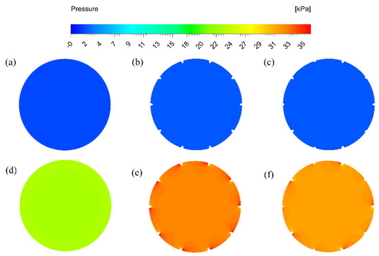
Figure 7.
Pressure contours at inlet cross-section (a) Smooth tube, Re 12,000; (b) Fin-to-Fin height 1:1, Re 12,000; (c) Fin-to-Fin height 1:2, Re 12,000; (d) Smooth tube, Re 54,000; (e) Fin-to-Fin height 1:1, Re 54,000; and, (f) Fin-to-Fin height 1:2, Re 54,000.
The contours clearly show that the pressure drop for helically finned tube with fin-to-fin height ratio of 1:2 is relatively less than the tube with fin-to-fin height ratio of 1:1. This indicates a better hydraulic performance for the fin-to-fin height ratio of 1:2. Keeping in view that the temperature drop for both helically finned tubes was almost similar. Both of these results indicate that a fin-to-fin height ratio of 1:2 has relatively better performance in terms of the pumping power required to obtain the heat transfer enhancement.
When the Re is low, the flow in both micro finned tubes remains attached to the wall, even though the micro fins have a significant effect on the introduction of turbulence. The strength of turbulence kinetic energy is higher in 1:1 tube as compared to 1:2 tube due to which the heat transfer and pressure drop is higher. The heat is being transferred to the wall from hot fluid in two ways. First. there is turbulence that transfers heat to the wall from rest of the fluid and second is the heat transfer in the vicinity of wall through the attached flow. When Re is small, the heat is being transferred through both ways in micro finned tubes. Therefore, because the turbulence kinetic energy is higher in 1:1 tube, the heat transfer is higher. At higher Re, the flow separates from the wall in 1:1 tube due to very high turbulence kinetic energy, but it still remains attached to the wall in case of 1:2 tube because of the smaller height of half of fins. Hence, less heat is now being transferred in 1:1 due to the separation of flow from the wall as compared to 1:2 tube. But the turbulence kinetic energy is still much higher in 1:1 tube. Accordingly, the overall heat transfer is balanced in both micro finned tubes at higher Re. That is why the temperature drop is almost equal in micro finned tubes at higher Re. Figure 8 and Figure 9 show the effect of turbulence kinetic energy on the attachment and detachment of flow in micro-finned tubes.
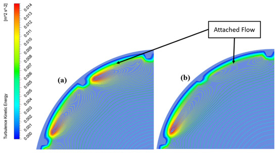
Figure 8.
Turbulence kinetic energy contours at Re 12,000 for (a) Equal fin height; (b) Alternating fin height.
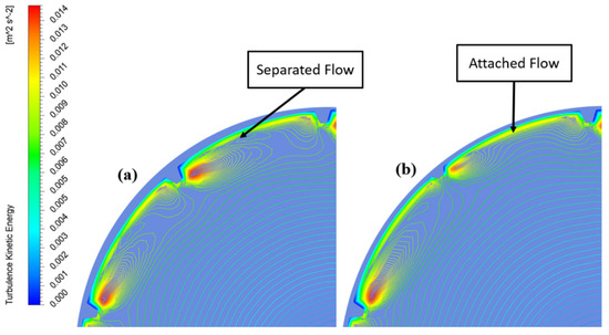
Figure 9.
Turbulence kinetic energy contours at Re 54,000 for (a) Equal fin height; (b) Alternating fin height.
Figure 10 shows the local pressure contours at the half length cross-section of both micro-finned tubes. The figure clearly shows slightly higher pressure drop values for equal fin height tube.
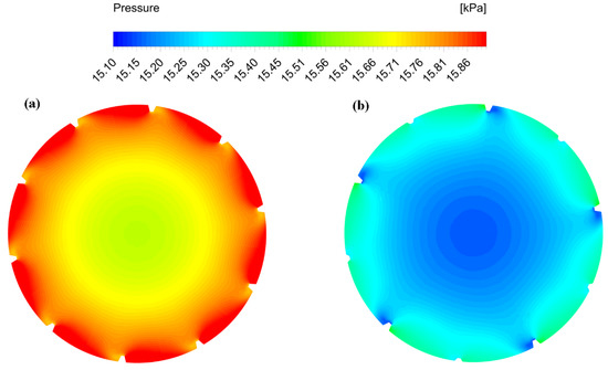
Figure 10.
Turbulence kinetic energy contours at Re 54,000 for (a) Equal fin height; (b) Alternating fin height.
Figure 11 shows the relative thermal and hydraulic performance of studied tubes. Nusselt number of micro-finned tubes is relatively greater than the smooth tube indicating a higher thermal performance across the whole range of Re. Both of the micro-finned tubes showed similar thermal performance. Thermal performance index of micro-finned tubes is greater than smooth tube for lower range of Re and it is less than smooth tube for higher Re. This indicates that micro-finned tubes show optimal performance for limited range of Re outside which they have poor performance as compared to smooth tubes. The figure also shows the improved thermal performance of tube with alternating fin height as compared with equal fin height tube. The range of Re in which the finned tubes perform better than smooth tube is also greater for alternating fin height tube.

Figure 11.
(a) Thermal performance index and (b) Nusselt number of the studied tubes.
Figure 12 shows the normalized friction factor and heat transfer coefficient with respect to smooth for both micro-finned tubes. The normalization is done to analyse the relative performance of micro-finned tubes with respect to the smooth tube and each other.

Figure 12.
(a) Friction factor and (b) Heat transfer coefficient, normalized with respect to smooth tube.
As compared to smooth tube, both of the helically finned tubes show higher heat transfer coefficient and pressure drop. As the Reynolds number increases, the flow is more dominated by pressure drop instead of heat transfer coefficient. When compared to equal fin height tube, alternating fin height tube has lower friction factor across the whole range of Re whereas the heat transfer coefficient is almost the same for both of the finned tubes. We can conclude, from the above discussion, that helically finned tube with alternating fin heights is a better choice for heat transfer augmentation because of the same thermal performance and relatively good hydraulic performance.
4. Conclusions
In this study, numerical simulations of turbulent flow for smooth and internal helically finned tubes with equal and alternating fin height were carried out. Water as working fluid was used with 55 °C inlet temperature, and walls of the tube were kept at a constant temperature of 20 °C. A simplified fluid domain was selected instead of complete experimental geometry to demonstrate the proof of concept. The computational solution was validated with the corresponding experimental and numerical work from literature, and the results showed relatively good agreement.
It was observed that heat transfer and pressure drop is increased in the case of helically finned tubes as compared to smooth tube. An average increase of 32% and 20% in friction factor and heat transfer coefficient, respectively, is observed in comparison with the smooth tube. The increase in heat transfer and pressure drop occurs due to helically swirling secondary flow near the fins of the micro finned tubes. The flow is dominated by pressure drop at higher Reynolds numbers. Thermal Performance Index of alternating fin height tube is relatively higher than the equal fin height tube. Additionally, the range of Re in which the Thermal Performance Index is greater than the smooth tube is also broader for alternating fin height tube. The comparative analysis of micro-finned tubes showed that alternating fin height tube has relatively better thermohydraulic performance. An average decrease of 5% in the friction factor was achieved at an average cost of <1% loss in heat transfer coefficient for alternating fin height tube as compared with equal fin height tube. Further investigation may focus on an optimized fin-to-fin height ratio. The number of fins and helix angle is kept constant in this study to benchmark the benefits of alternating fin heights. A better passive cooling solution may be achieved by incorporating all of the geometrical parameters of helically finned tube and using a competitive optimization technique.
Author Contributions
M.S. conceived the idea. M.A.A. conducted the experiment, and prepared initial draft of manuscript. E.U., N.B. and Z.A. contributed ideas and resources. M.S., E.U. provided supervision. M.S. and M.A.A. analysed data. M.S. reviewed and edited manuscript. All authors have read and agreed to the published version of the manuscript.
Funding
This research received no external funding.
Institutional Review Board Statement
Not applicable.
Informed Consent Statement
Not applicable.
Data Availability Statement
All the data used in this paper can be obtained upon request from the corresponding author.
Conflicts of Interest
The authors declare that they have no conflict of interest.
Nomenclature
| b | fin base width, [m] | turbulence kinetic energy due to buoyancy, [J/kg] | |
| c | fin top width, [m] | turbulence kinetic energy due to mean velocity gradients, [J/kg] | |
| specific heat, [J/kg.K] | Prandtl number | ||
| User defined constants | Reynolds number | ||
| tube diameter, [m] | strain tensor | ||
| e | fin height, [m] | heat source term, [W/m2] | |
| total energy, [J] | , | turbulence source terms, [J/kg] | |
| f | friction factor | 3D temperature array, [K] | |
| external forces, [N] | T | temperature, [K] | |
| gravitational force, [N] | time averaged velocity | ||
| heat transfer coefficient, [W/m2.K] | inlet uniform velocity, [m/s] | ||
| sensible enthalpy, [J] | velocity vector, [m/s] | ||
| diffusion flux, [kg/m2.s] | Cartesian vector | ||
| turbulence kinetic energy, [J/kg] | fluctuating dilatation, [J/kg] | ||
| thermal conductivity, [W/m.K] | Greek Symbols | ||
| effective thermal conductivity, [W/m.K] | helix angle, [deg] | ||
| tube length, [m] | turbulence energy dissipation, [J/kg] | ||
| mass flow rate, [kg/s] | thermal performance index | ||
| helical Fin pitch, [m] | dynamic viscosity, [Pa.s] | ||
| number of fins | Eddy viscosity, [Pa.s] | ||
| Nusselt number | deviatoric stress tensor | ||
| fluid static pressure, [Pa] | kinematic viscosity, [m2/s] | ||
| , | turbulence Prandtl numbers | fluid density, [kg/m3] | |
| stress tensor | |||
| Subscripts | |||
| b | bulk fluid | in | inlet |
| finned | finned tube | o | outer |
| h | hydraulic | out | outlet |
| i | inner | w | wall |
References
- Ji, W.-T.; Jacobi, A.M.; He, Y.-L.; Tao, W.-Q. Summary and evaluation on single-phase heat transfer enhancement techniques of liquid laminar and turbulent pipe flow. Int. J. Heat Mass Transf. 2015, 88, 735–754. [Google Scholar] [CrossRef]
- Kim, S.; Kim, M.; Park, Y.G.; Min, J.K.; Ha, M.Y. Numerical investigation of fluid flow and heat transfer characteristics in a helically-finned tube. J. Mech. Sci. Technol. 2017, 31, 3271–3284. [Google Scholar] [CrossRef]
- Alam, T.; Kim, M.-H. A comprehensive review on single phase heat transfer enhancement techniques in heat exchanger applications. Renew. Sustain. Energy Rev. 2018, 81, 813–839. [Google Scholar] [CrossRef]
- Duan, L.; Ling, X.; Peng, H. Flow and heat transfer characteristics of a double-tube structure internal finned tube with blossom shape internal fins. Appl. Therm. Eng. 2018, 128, 1102–1115. [Google Scholar] [CrossRef]
- Huang, S.; Zhu, H.; Zheng, Y.; Wan, Z.; Tang, Y. Compound thermal performance of an arc-shaped inner finned tube equipped with Y-branch inserts. Appl. Therm. Eng. 2019, 152, 475–481. [Google Scholar] [CrossRef]
- Ahmed, S.A.E.S.; Ibrahim, E.Z.; Ibrahim, M.M.; Essa, M.A.; Abdelatief, M.A.; El-Sayed, M.N. Heat transfer performance evaluation in circular tubes via internal repeated ribs with entropy and exergy analysis. Appl. Therm. Eng. 2018, 144, 1056–1070. [Google Scholar] [CrossRef]
- Aroonrat, K.; Wongwises, S. Experimental investigation of condensation heat transfer and pressure drop of R-134a flowing inside dimpled tubes with different dimpled depths. Int. J. Heat Mass Transf. 2019, 128, 783–793. [Google Scholar] [CrossRef]
- Chen, J.; Li, W. Local flow boiling heat transfer characteristics in three-dimensional enhanced tubes. Int. J. Heat Mass Transf. 2018, 121, 1021–1032. [Google Scholar] [CrossRef]
- Meyer, J.; Abolarin, S. Heat transfer and pressure drop in the transitional flow regime for a smooth circular tube with twisted tape inserts and a square-edged inlet. Int. J. Heat Mass Transf. 2018, 117, 11–29. [Google Scholar] [CrossRef]
- Shishkin, A.; Kanizawa, F.T.; Ribatski, G.; Tarasevich, S.; Yakovlev, A. Experimental investigation of the heat transfer coefficient during convective boiling of R134a in tubes with twisted tape insert. Int. J. Refrig. 2018, 92, 196–207. [Google Scholar] [CrossRef]
- Shi, J.; Zheng, G.; Chen, Z. Experimental investigation on flow condensation in horizontal tubes filled with annular metal foam. Int. J. Heat Mass Transf. 2018, 116, 920–930. [Google Scholar] [CrossRef]
- Wang, X.; Ho, J.; Leong, K.; Wong, T. Condensation heat transfer and pressure drop characteristics of R-134a in horizontal smooth tubes and enhanced tubes fabricated by selective laser melting. Int. J. Heat Mass Transf. 2018, 126, 949–962. [Google Scholar] [CrossRef]
- Sajadi, B.; Soleimani, M.; Akhavan-Behabadi, M.; Hadadi, E. The effect of twisted tape inserts on heat transfer and pressure drop of R1234yf condensation flow: An experimental study. Int. J. Heat Mass Transf. 2020, 146, 118890. [Google Scholar] [CrossRef]
- Zhai, C.; Islam, M.; Simmons, R.; Barsoum, I. Heat transfer augmentation in a circular tube with delta winglet vortex generator pairs. Int. J. Therm. Sci. 2019, 140, 480–490. [Google Scholar] [CrossRef]
- Dastmalchi, M.; Arefmanesh, A.; Sheikhzadeh, G. Numerical investigation of heat transfer and pressure drop of heat transfer oil in smooth and micro-finned tubes. Int. J. Therm. Sci. 2017, 121, 294–304. [Google Scholar] [CrossRef]
- Eiamsa-Ard, S.; Wongcharee, K. Single-phase heat transfer of CuO/water nanofluids in micro-fin tube equipped with dual twisted-tapes. Int. Commun. Heat Mass Transf. 2012, 39, 1453–1459. [Google Scholar] [CrossRef]
- Celen, A.; Dalkilic, A.S.; Wongwises, S. Experimental analysis of the single phase pressure drop characteristics of smooth and microfin tubes. Int. Commun. Heat Mass Transf. 2013, 46, 58–66. [Google Scholar] [CrossRef]
- Naphon, P.; Sriromruln, P. Single-phase heat transfer and pressure drop in the micro-fin tubes with coiled wire insert. Int. Commun. Heat Mass Transf. 2006, 33, 176–183. [Google Scholar] [CrossRef]
- Pirbastami, S.; Moujaes, S.F.; Mol, S.G. Computational fluid dynamics simulation of heat enhancement in internally helical grooved tubes. Int. Commun. Heat Mass Transf. 2016, 73, 25–32. [Google Scholar] [CrossRef]
- Jensen, M.K.; Vlakancic, A. Technical Note Experimental investigation of turbulent heat transfer and fluid flow in internally finned tubes. Int. J. Heat Mass Transf. 1999, 42, 1343–1351. [Google Scholar] [CrossRef]
- Copetti, J.B.; Macagnan, M.H.; De Souza, D.; Oliveski, R.D.C. Experiments with micro-fin tube in single phase. Int. J. Refrig. 2004, 27, 876–883. [Google Scholar] [CrossRef]
- Han, D.H.; Lee, K.-J. Single-phase heat transfer and flow characteristics of micro-fin tubes. Appl. Therm. Eng. 2005, 25, 1657–1669. [Google Scholar] [CrossRef]
- Li, X.-W.; Meng, J.-A.; Li, Z.-X. Experimental study of single-phase pressure drop and heat transfer in a micro-fin tube. Exp. Therm. Fluid Sci. 2007, 32, 641–648. [Google Scholar] [CrossRef]
- Zdaniuk, G.J.; Chamra, L.M.; Mago, P.J. Experimental determination of heat transfer and friction in helically-finned tubes. Exp. Therm. Fluid Sci. 2008, 32, 761–775. [Google Scholar] [CrossRef]
- Ağra, Ö.; Demir, H.; Atayılmaz, Ş.Ö.; Kantaş, F.; Dalkılıç, A.S. Numerical investigation of heat transfer and pressure drop in enhanced tubes. Int. Commun. Heat Mass Transf. 2011, 38, 1384–1391. [Google Scholar] [CrossRef]
- Baba, M.S.; Raju, A.S.R.; Rao, M.B. Heat transfer enhancement and pressure drop of Fe3O4 -water nanofluid in a double tube counter flow heat exchanger with internal longitudinal fins. Case Stud. Therm. Eng. 2018, 12, 600–607. [Google Scholar] [CrossRef]
- Solanki, A.K.; Kumar, R. Condensation of R-134a inside micro-fin helical coiled tube-in-shell type heat exchanger. Exp. Therm. Fluid Sci. 2018, 93, 344–355. [Google Scholar] [CrossRef]
- Chen, H.; Wan, Z.; Mo, H.; Huang, S.; Tang, Y. Experimental studies on the compound thermo-hydraulic characteristics in a 3D inner finned tube with porous copper fiber inserts. Int. Commun. Heat Mass Transf. 2019, 100, 51–59. [Google Scholar] [CrossRef]
- CYang, C.-M.; Hrnjak, P. Effect of straight micro fins on heat transfer and pressure drop of R410A during evaporation in round tubes. Int. J. Heat Mass Transf. 2018, 117, 924–939. [Google Scholar] [CrossRef]
- Lin, Y.; Li, J.; Chen, Z.; Li, W.; Ke, Z.; Ke, H. Two-Phase Flow Heat Transfer in Micro-Fin Tubes. Heat Transf. Eng. 2021, 42, 369–386. [Google Scholar] [CrossRef]
- Tanga, W.; Li, W.; Minkowycz, W.J. A numerical investigation of convective condensation in micro-fin tubes of different geometries. Numer. Heat Transfer Part A Appl. 2020, 78, 697–705. [Google Scholar] [CrossRef]
- Wei, L. Study on comprehensive performance evaluation for condensation heat transfer inside the micro-fin tube. Adv. Mech. Eng. 2020, 12. [Google Scholar] [CrossRef]
Publisher’s Note: MDPI stays neutral with regard to jurisdictional claims in published maps and institutional affiliations. |
© 2021 by the authors. Licensee MDPI, Basel, Switzerland. This article is an open access article distributed under the terms and conditions of the Creative Commons Attribution (CC BY) license (https://creativecommons.org/licenses/by/4.0/).