Abstract
To investigate the flow-field characteristics of a submerged pre-mixed abrasive water jet impinging on a wall, a physical model of the conical–cylindrical nozzle and computation domain of a submerged pre-mixed abrasive-water-jet flow field were established. Based on the software of FLUENT 2022R2, numerical simulation of the solid–liquid two-phase flow characteristics of the submerged pre-mixed abrasive water jet impinging on a wall was conducted using the DPM particle trajectory model and the realizable
turbulence model. The simulation results indicate that a “water cushion layer” forms when the submerged pre-mixed abrasive water jet impinges on a wall. Tilting the nozzle appropriately facilitates the rapid dispersion of water and abrasive particles, which is beneficial for cutting. The axial-jet velocity increases rapidly in the convergent section of the nozzle, continues to accelerate over a certain distance after entering the cylindrical section, reaches its maximum value inside the nozzle, and then decelerates to a steady value before exiting the nozzle. In addition, the standoff distance has minimal impact on the flow-field characteristic inside the nozzle. When impinging on a wall surface, rapid decay of axial-jet velocity generates significant stagnation pressure. The stagnation pressure decreases with increasing standoff distance for different standoff-distance models. Considering the effects of standoff distance on jet velocity and abrasive particle dynamics, a standoff distance of 5 mm is determined to be optimal for submerged pre-mixed abrasive-water-jet pipe-cutting operations. When the submergence depth is less than 100 m, its effect on the flow-field characteristics of a submerged pre-mixed abrasive water jet impinging on a wall surface remains minimal. For underwater oil pipelines operating at depths not exceeding 100 m, the influence of submergence depth can be disregarded during cutting operations.
1. Introduction
Pipeline transportation is a crucial means of oil and gas transportation [1]. In the event of emergency repair or maintenance operations on oil and gas pipelines, it is often necessary to cut the damaged section of the pipeline. The cutting of certain oil pipelines, such as submarine pipelines laid underwater, requires underwater operations. The challenging environmental conditions inherent to such tasks contribute to their complexity and difficulty. Currently, underwater cutting methods include energy-focused cutting, chemical cutting, arc-oxygen cutting, mechanical cutting, diamond-wire-saw cutting, and abrasive-water-jet cutting, among others [2,3,4]. Abrasive-water-jet cutting technology offers explosion-proof safety, pollution-free operation, no thermal stress, and material versatility, making it ideal for underwater structural cutting tasks [5,6,7]. Depending on the abrasive feeding method, abrasive-water-jet (AWJ) technology is divided into two types: pre-mixed AWJ (abrasive mixed with water upstream of the nozzle) and post-mixed AWJ (abrasive injected downstream of the nozzle) [8]. Compared to the post-mixed abrasive water jet, in the pre-mixed abrasive water jet, the abrasive and water are thoroughly mixed in the delivery pipe upstream of the nozzle. This facilitates energy transfer from the high-pressure water to the abrasive, resulting in stronger cutting capability under the same pressure conditions [9]. Numerous researchers have conducted numerical simulations and experimental investigations into the flow-field characteristics, energy transfer mechanisms, and material interaction laws of non-submerged pre-mixed abrasive water jets [10,11,12,13,14]. However, comparatively few studies on the submerged pre-mixed abrasive water jet (SPAWJ) have been conducted. Some researchers have performed experimental investigations into the erosive characteristics of submerged abrasive water jets, focusing particularly on how operational parameters affect material removal rates [15,16,17]. Zeng S performed numerical simulations to investigate the effects of nozzle structural parameters, abrasive properties, and submerged water flow velocity on the internal and external flow-field characteristics of a pre-mixed abrasive-water-jet nozzle [18]. Taking a specific conical–straight nozzle as the research object, Wang et al. conducted numerical simulations to investigate the effects of jet standoff distance, abrasive particle diameter, and abrasive concentration on the flow-field characteristics of submerged abrasive jets [19]. Huang et al. used FLUENT 2022R2 to simulate the velocity distribution in a submerged pre-mixed abrasive-water-jet (SPAWJ) flow field [20]. Cui H performed numerical simulations of both internal and external flow fields in submerged pre-mixed abrasive water jets, analyzing the influence patterns of nozzle structural parameters on flow characteristics [21]. Wang et al. conducted design and simulation research on a pre-mixed abrasive-water-jet underwater cutting device [22]. Under submerged conditions, the presence of a target obstruction exerts certain effects on the characteristics of pre-mixed abrasive water jets. Experimental studies on pre-mixed submerged abrasive water jets (SAWJ) are conducted by integrating target objects, aiming to derive corresponding experimental characteristics and patterns. However, very few studies have employed numerical simulation to investigate the flow field around target walls in conjunction with pre-mixed submerged AWJ systems. This study focuses on underwater cutting using pre-mixed abrasive-water-jet (AWJ) technology. Using cutting nozzles commonly employed in engineering as the research subject, the influences of standoff distance and submergence depth on the flow-field characteristics of a submerged pre-mixed AWJ impinging on a wall were investigated through numerical simulations. This research aims to provide references for the application of pre-mixed AWJ technology in underwater pipeline cutting.
2. Physics Model
The nozzle is a conventional pre-mixed abrasive-water-jet (AWJ) nozzle for cutting applications, namely a conical–cylindrical nozzle. Its geometric model is shown in Figure 1, with all dimensions in millimeters (mm). The nozzle comprises a conical inlet convergent section and a cylindrical section, with a total length of 76.2 mm. The cylindrical section measures 70.135 mm in length with an internal diameter of 1 mm.

Figure 1.
Longitudinal section view of geometric structure of the conical–cylindrical nozzle.
3. Mathematical Model
The submerged pre-mixed abrasive water jet (SPAWJ) is a complex flow characterized by solid–liquid two-phase interaction, high velocity, and turbulent behavior with high Reynolds numbers. Therefore, the Discrete Phase Model (DPM) and realizable turbulence model were considered in the numerical simulation calculation of the submerged pre-mixed abrasive water jet.
3.1. Discrete Phase Model
The Discrete Phase Model (DPM) in FLUENT 2022R2 is a multiphase flow model used to simulate the movement characteristics of discrete particles in a fluid, with consideration of interphase coupling. It is primarily applicable to cases where the volume fraction of the dispersed phase is less than 12% [23,24]. To obtain the trajectory information of abrasive particles, DPM was employed to simulate the continuous phase (water) by solving the Navier–Stokes (N-S) equations in an Eulerian framework, while the discrete phase (abrasive particles) was tracked using the Lagrangian particle trajectory equations. This approach revealed the flow-field characteristics of the submerged abrasive water jet. Considering the low volume fraction of abrasive particles (5%, meeting the requirement for the dispersed phase volume fraction in DPM simulations) in the submerged pre-mixed abrasive water jet, particle–particle interactions and the effect of abrasive particles on the continuous phase were neglected. Only the one-way coupling from the continuous phase to the discrete phase was considered [25]. The trajectory of the discrete-phase abrasive particles can be obtained by integrating the following particle force balance equation in the Lagrangian coordinate system [26]:
where represents the specific force on the particle; is the velocity of the continuous phase; is the velocity of the discrete phase. Simultaneously,
where represents the dynamic viscosity of the fluid; is the density of the continuous phase; is the density of the particle; is the diameter of the particle; is the drag coefficient; and stands for the particle Reynolds number, calculated as follows:
where is the gravitational acceleration in the X-direction; represents other forces in the X-direction, including apparent mass force, thermophoretic force, Brownian force, Saffman lift force, etc. It is assumed that the abrasive particles are spherical, with a diameter of 0.18 mm; for this, “Mesh” denotes the number of openings per inch (25.4 mm) on a sieve screen. Assuming the abrasive used in the numerical simulation is standard 80-grit abrasive—defined as particles that cannot pass through an 80-mesh sieve but can pass through the next coarser grade (i.e., a 70-mesh sieve)—since the opening diameter of an 80-mesh sieve is 0.18 mm, this value (0.18 mm) is adopted as the representative or nominal diameter for the 80-grit abrasive. Due to the small size of the abrasive particles (0.18 mm) and the significant difference in density between the water phase and the abrasive particles (garnet, density 3900 kg/m3), all other forces are neglected [27].
3.2. Turbulence Model
Currently, methods for simulating turbulent flows can be categorized into three main classes: Direct Numerical Simulation (DNS), Scale-Resolving Simulation (SRS), and Reynolds Average Navier–Stokes (RANS). Scale-Resolving Simulation, which bridges the gap between DNS and RANS, includes Large-Eddy Simulation (LES), Scale-Adaptive Simulation (SAS), and Detached Eddy Simulation (DES), among others. The first two methods (DNS and SRS) are computationally intensive. Although the Reynolds Average Navier–Stokes (RANS) approach has the drawback of heavy reliance on empirical turbulence closure schemes, it was selected for this study to reduce computational costs [28,29]. RANS decomposes the instantaneous variables in the Navier–Stokes equations into mean and fluctuating components. By substituting the time-averaged velocity into the continuity and momentum equations, the governing equations of RANS are derived.
The additional Reynolds stress term in the equation is closed using an eddy viscosity model. Among the commonly used eddy viscosity models, the family is prevalent, including the Standard , RNG , and realizable model. Due to its higher accuracy in predicting the spread rate of cylinder jets, the realizable model is commonly used as the solving model for jet flows [30,31]. The governing equations for turbulent kinetic energy and dissipation rate are outlined below:
In the above-mentioned equations, and are the turbulent Prandtl numbers for and , respectively; represents the generation of turbulence kinetic energy due to the mean velocity Gradients; is the generation of turbulence kinetic energy due to buoyancy; is the mean rate-of-rotation tensor viewed in a moving reference frame with the angular velocity ; represents the turbulent Prandtl number for energy, which is set to 0.85 in the realizable mode; is the component of the gravitational vector in the direction; is the coefficient of thermal expansion. The model constants are = 1.44, = 0.09, = 1.92, = 1.0, = 1.2, = 4.04.
4. Numerical Simulation
4.1. Mesh Generation
To simulate the flow-field characteristics of a submerged pre-mixed abrasive water jet (SPAWJ) cutting steel plates, pipelines, and other materials, the research domain is defined as the interior flow channel of a conical–cylindrical nozzle and the spatial region extending from the nozzle exit to the material surface. Additionally, considering the axisymmetric nature of the submerged pre-mixed abrasive water jet (SPAWJ) when vertically impinging on a wall, a three-dimensional model is simplified to two-dimensional, and an axisymmetric modeling approach is adopted in order to reduce computational costs. Only half of the cross-sectional domain, symmetric about the nozzle axis, is selected as the computational domain. The geometric model of the computational domain is shown in Figure 2, where the origin (x = 0) corresponds to the nozzle exit cross-section and the positive X-axis aligns with the jet direction. All length dimensions in Figure 2 are given in millimeters (mm), and the magnitude of angle α is 20°. This coordinate system is consistently applied to all data figures except where specifically stated/noted. The mesh generation is performed using ICEM CFD 2022 R2. Due to the simplicity of the geometric model, a structured meshing approach is employed to enhance computational accuracy. Figure 3 illustrates the mesh layout, with local grid refinement applied in the nozzle convergent section, at the nozzle exit, and near the wall regions.

Figure 2.
Geometric model of the computational domain.

Figure 3.
Calculation mesh.
To validate grid independence, three sets of meshes with different numbers of elements were generated for the computational domain model featuring a standoff distance of 5 mm (Mesh 1: 9718; Mesh 2: 23,908; Mesh 3: 71,182). Numerical simulations of submerged pre-mixed abrasive water jets were conducted for each mesh configuration, yielding the axial-jet velocity distribution at the nozzle exit shown in Figure 4.
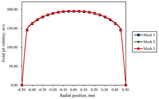
Figure 4.
Axial-jet velocity distribution at the nozzle outlet.
As shown in Figure 4, the axial-jet velocity distribution curves at the nozzle outlet for all three meshes are largely identical. Notably, the curves for Mesh 2 and Mesh 3 nearly overlap. The accuracy of all three meshes satisfies the computational requirements. To ensure result accuracy while maintaining computational efficiency, Mesh 2 was selected as the computational grid. Using the resolution of Mesh 2 as the benchmark, the other four standoff-distance models were meshed with equivalent precision. Table 1 presents the meshing results for the computational domain models with different standoff distances.

Table 1.
Mesh generation results for computational domain models with different standoff distances.
4.2. Computational Strategy
The governing equations are discretized using the finite volume method. Although the submerged pre-mixed abrasive-water-jet (SPAWJ) process is unsteady, the fluctuations in flow parameters are much smaller than their mean values. In addition, since our study focuses on the macroscopic average behavior, a pressure-based solver is employed for steady-state computations. Due to the high jet velocity, the effect of gravity on jet development is neglected. The pressure–velocity coupling is resolved using the SIMPLEC algorithm, and turbulence is defined via the intensity and hydraulic diameter method. The inlet boundary of the computational domain is set as a pressure inlet with a pressure of 30 MPa, while the outlet boundary is configured as a pressure outlet. Both the nozzle wall surface and material wall are assigned wall boundary conditions (wall), with a no-slip condition applied to their internal surfaces. Near the walls, the standard wall function is employed. The jet axis is defined as a symmetry axis (axis). It is assumed that the collisions between abrasive particles and the wall are perfectly elastic. In the DPM model, the collision behavior of abrasive particles with the nozzle wall and material walls is set to “reflect”, while their behavior at the inlet and outlet boundaries is set to “escape”. In the submerged pre-mixed abrasive water jet, the abrasive particles have undergone significant acceleration over a long distance before reaching the nozzle inlet, and their velocity approaches that of the water [32]. The initial velocity of the abrasive particles is set to 10 m/s. The particle injection source is defined at the inlet boundary, with a mass flow rate of 0.03 kg/s for the abrasive particles. In the numerical simulation, the stochastic walk model is employed to account for the interactions between the abrasive particles and the discrete eddies in the water phase.
4.3. Experimental Validation of Numerical Simulations
To verify the accuracy of numerical simulations, flow-rate-measurement experiments were conducted using a pre-mixed abrasive-water-jet experiment system, as shown in Figure 5. This system primarily consists of a high-pressure generator (Anhui Aoyu CNC Technology Co., Ltd., Chuzhou, Anhui, China), abrasive tank (Anhui Aoyu CNC Technology Co., Ltd., Chuzhou, Anhui, China), high-pressure piping (Spir Star GmbH, Neuried, Germany), handheld cutting spray gun (Anhui Aoyu CNC Technology Co., Ltd., Chuzhou, Anhui, China), and collection bucket (Luoyang Longrui Office Furniture Co., Ltd., Luoyang, Henan, China). Specifically, the outlet of the high-pressure generator is connected to the inlet of the abrasive tank, while its outlet feeds into the handheld spray gun via a flexible high-pressure hose. The nozzle is mounted at the distal end of the gun. Its operational principle is as follows: Low-pressure water undergoes pressurization by the high-pressure pump, then transits through the reinforced hose into the abrasive tank, where it admixes with particles (80-grit garnet, Jiangsu Jinhong New Materials Co., Ltd., Lianyungang, Jiangsu, China) in a fixed ratio to form a solid–liquid two-phase mixture. This slurry is ultimately ejected through the nozzle on the spray gun, generating the pre-mixed abrasive water jet. The detailed experimental procedure for flow-rate determination includes the following:
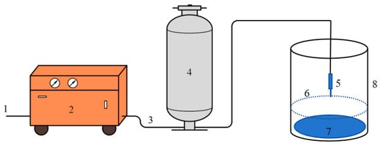
Figure 5.
Schematic diagram of pre-mixed abrasive-water-jet experiment system. 1—water source inlet; 2—high-pressure generator; 3—high-pressure piping; 4—abrasive tank; 5—nozzle; 6—water surface; 7—steel plate; 8—collection bucket.
- (1)
- Prepare a collection bucket with a steel plate placed at its bottom to prevent jet penetration. Add water to a depth of 30 cm within the collection bucket. Weigh the entire assembly (including water, steel plate, and collection bucket) using an electronic balance and record the initial mass as M1.
- (2)
- After charging the abrasive tank with abrasive, initiate the pre-mixed abrasive-water-jet experiment system. Adjust the discharge pressure of the plunger pump in the high-pressure generator to 30 MPa. When the discharge pressure stabilizes, promptly redirect the handheld cutting spray gun into the collection bucket with its nozzle outlet submerged below the water surface to form a submerged pre-mixed abrasive water jet. After sustaining continuous jetting for 3 min, withdraw the gun. Upon cessation of jetting, reweigh the entire assembly and record the final mass as M2. The differential mass (M2 − M1) represents the total weight of the abrasive–water mixture injected into the collection bucket by the pre-mixed abrasive water jet. Dividing this value by time t (where t = 3 min) yields the mass flow rate of the pre-mixed abrasive water jet: (M2 − M1)/t.
Conduct the experiment twice, and take the average of the two measured results as the experimental outcome. The experimental results are shown in Table 2.

Table 2.
Experimental results of the flow-rate-measurement experiments.
A computational domain model with a standoff distance of 1 mm was employed as the simulation object. Steady-state calculations for the submerged pre-mixed abrasive water jet were conducted following the computational strategy described in Section 4.2, iterating for 5000 steps until convergence was achieved. The outlet mass-flow-rate monitoring curve is illustrated in Figure 6. The numerical results indicate an exit flow rate of 0.131027 kg/s at the nozzle outlet. This value exhibits excellent agreement with experimental measurements, showing a minimal discrepancy of only 0.030661 kg/s, thereby validating the accuracy of the numerical simulation. Potential sources of error include the following: (1) A non-submerged pre-mixed abrasive water jet is created when relocating the handheld cutting spray gun from outside the collection bucket to submerging its nozzle outlet below the water surface, which may have slightly increased the flow rate; (2) deviations between the actual submergence depth during experiments and the simulated value (30 cm); and (3) experimental measurement errors.
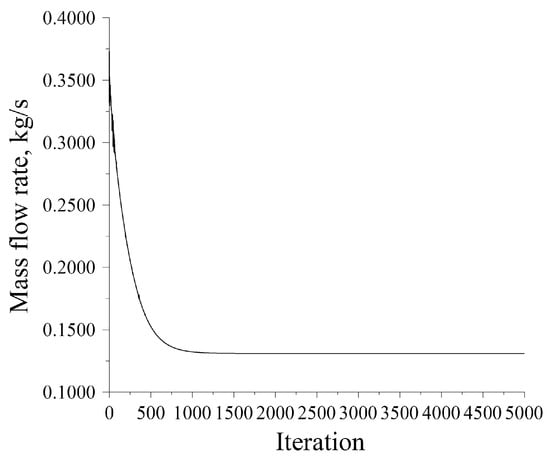
Figure 6.
Monitoring of nozzle outlet mass flow rate in simulation.
4.4. Simulation Results and Analysis
4.4.1. Influence of Standoff Distance on the Flow-Field Characteristics of the Submerged Pre-Mixed Abrasive Water Jet
The submergence depth of the pre-mixed abrasive-water-jet cutting is maintained at 30 cm, corresponding to a constant pressure of 2941.98 Pa (equivalent to a 30 cm water column) at the pressure outlet boundary. The standoff distances are varied as 1 mm, 5 mm, 9 mm, 11 mm, and 15 mm, and different computational domain models are constructed for numerical simulation. In all models, the jet direction is perpendicular to the target wall.
- (1)
- Velocity distribution
Figure 7 shows the velocity contour plots for different standoff-distance models. As observed in the figure, the velocity increases rapidly in the nozzle convergent section and continues to rise in the nozzle cylinder section. After exiting the nozzle, the velocity decreases sharply within the standoff distance range. In Figure 7a, when the standoff distance is 1 mm, the jet core region is not fully developed, and the jet reaches the wall before full development, then diverges radially. As shown in Figure 7b–e, the pre-mixed abrasive water jet clearly exhibits a distinct jet core region (the red area in the initial jet segment between the nozzle exit and the wall) within the standoff-distance range. For standoff distances of 9 mm, 11 mm, and 15 mm, the jet core region is fully developed. The length of the jet core region remains nearly constant across different standoff distances. Beyond the jet core region, the velocity decreases rapidly, and the entire jet spreads into a conical shape. Additionally, as seen in Figure 7, a “water cushion layer” with a definite thickness and a comparatively low jet velocity develops adjacent to the wall when the jet impinges on the wall. When the jet impinges into the water cushion, it undergoes intense friction with the relatively low-speed water body, thereby dissipating and dispersing its enormous kinetic energy. This is detrimental to the erosive action of abrasive particles on the target material. It can be anticipated that, when using a submerged pre-mixed abrasive water jet (SPAWJ) to cut submarine pipelines, the vertical jet is not conducive to the rapid dispersion of water and abrasive particles after the cut is formed. Tilting the nozzle appropriately facilitates the rapid dispersion of water and abrasive particles, which is beneficial for cutting.
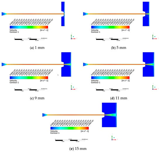
Figure 7.
Velocity contour plots of different standoff-distance models.
Figure 8 shows the variation curves of axial-jet velocity along the centerline within nozzles for different standoff-distance models. As observed in Figure 8, the axial-jet velocity increases rapidly in the convergent section of the nozzle, continues to accelerate over a certain distance after entering the cylindrical section, reaches its maximum value inside the nozzle, and then decelerates to a steady value before exiting the nozzle. The axial-jet-velocity variation trends along the nozzle centerline exhibit high similarity, namely nearly overlapping for different standoff-distance models. This indicates that external environmental factors—that is to say, the standoff distances—have a minimal impact on the internal flow field.
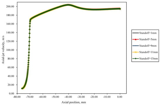
Figure 8.
Variation curve of axial-jet velocity along the centerline within nozzles for different standoff-distance models.
Figure 9 shows the variation curves of axial-jet velocity along the centerline in the external flow field of nozzles for different standoff-distance models. Simulation results indicate that at standoff distances of 1 mm, 5 mm, 9 mm, 11 mm, and 15 mm, the axial-jet velocities at the nozzle exit are 192.76 m/s, 195.43 m/s, 194.84 m/s, 194.83 m/s, and 194.83 m/s, respectively. Namely, as observed in Figure 6, the axial-jet velocity at the nozzle exit is lower than that for other standoff distances when the standoff distance is 1 mm. In addition, the axial-jet velocity at the nozzle exit is approximate for standoff distances of 5 mm, 9 mm, 11 mm, and 15 mm. For standoff distances of 1 mm and 5 mm, the axial-jet velocity drops rapidly to zero within a short distance near the wall surface. For standoff distances of 5 mm, 9 mm, 11 mm, and 15 mm, the axial-jet velocity profile exhibits a repeated segment approximately 3.8 mm long. At standoff distances of 9 mm, 11 mm, and 15 mm, the axial-jet velocity begins decreasing at a faster rate starting around x = 6.094 mm. This indicates that with an inlet pressure of 30 MPa, the submerged pre-mixed abrasive water jet (SPAWJ) has a core section approximately 6 mm long. At a standoff distance of 5 mm, the jet core is not fully developed, and its core section is not completely visible. Within the length of the jet core section, the axial-jet velocity profile along the centerline is identical for different standoff-distance models. Beyond the length of the jet core section, the rate of decrease in the axial-jet velocity becomes slower as the standoff distance increases.
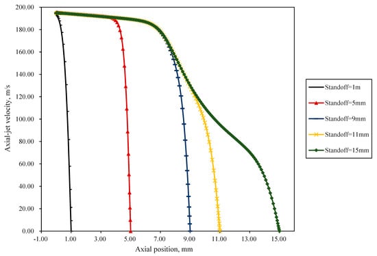
Figure 9.
Variation curve of axial-jet velocity along the centerline in the external flow field for different standoff-distance models.
- (2)
- Pressure distribution
Figure 10 presents the pressure contour plots for different standoff-distance models. Jet pressure peaks at the nozzle inlet and decreases progressively along the jet direction within the nozzle. Upon exiting the nozzle, the jet pressure approaches ambient levels. When impinging on the wall surface, rapid decay of axial-jet velocity generates significant stagnation pressure. Figure 11 illustrates the pressure distribution curves along the centerline for different standoff-distance models. Notably, high pressure gradients occur both in the convergent section and adjacent to the wall surface. Although stagnation pressure decreases with increasing standoff distance, the practical cutting depth at 5 mm standoff distance may not be less than that at 1 mm. This occurs because the cutting efficiency of an abrasive water jet is predominantly determined by particle velocity rather than stagnation pressure. At 1 mm standoff, flow near the wall becomes severely choked, resulting in a relatively poor overall acceleration effect of the abrasive particles.
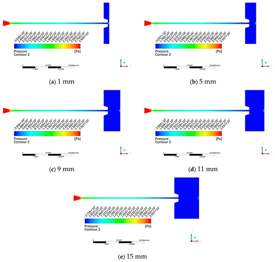
Figure 10.
Jet pressure contour plots for different standoff-distance models.
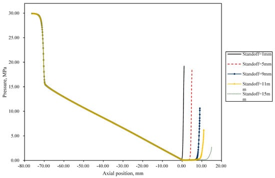
Figure 11.
Variation curve of jet pressure along the centerline for different standoff-distance models.
- (3)
- Motion behavior of abrasive particles
Figure 12 presents the particle trajectory plots for different standoff-distance models, with twenty randomly selected particles for each model configuration. As observed in the figure, the general rule of the velocity variations in abrasive particles for different standoff-distance models exhibits similar trends to the jet velocity profiles shown in Figure 7. Namely, the velocity of abrasive particles increases rapidly in the nozzle convergent section and continues to rise in the nozzle cylinder section. After exiting the nozzle, the velocity of abrasive particles decreases sharply within the standoff-distance range. Notably, at 5 mm standoff distance, distinct rebound phenomena are observed, which is attributed to elastic collisions with the solid wall; however, none of the rebounding abrasive particles return to the nozzle, and the rebound velocity of abrasive particles remains relatively low—a finding corroborated by the trajectory visualizations in Figure 13. By inference, analogous rebound phenomenon should occur at a 1 mm standoff distance; however, there is no apparent rebound phenomenon as shown in Figure 12a, which can likely be attributed to the obscuring of rebounding abrasive particles’ motion trajectories by forward-moving counterparts. Due to the short standoff distance, there may be rebounded abrasive particles striking the nozzle orifice, causing wear at the orifice. This may not only shorten the nozzle’s service life but also adversely affect the quality of the jet stream. At standoff distances of 9 mm, 11 mm, and 15 mm, the velocity of abrasive particles upon reaching the solid surface decreases significantly compared to that at the nozzle exit, which is detrimental to enhancing the cutting efficiency of abrasive-water-jet systems.
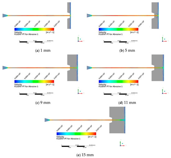
Figure 12.
Particle trajectory plots for different standoff-distance models.
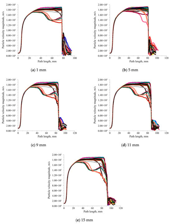
Figure 13.
Particle velocity versus trajectory length curves for different standoff-distance models.
Figure 13 presents the particle velocity versus trajectory length curves for different standoff-distance models. Each plot displays 20 randomly selected particle velocity profiles represented in 20 different colors, with the abscissa representing the traveled trajectory length and the ordinate indicating particle velocity magnitude. Abrupt velocity changes correspond to wall impact locations. Beyond the end of the curves indicates that abrasive particles have escaped from the computational domain; these are identical in the subsequent particle trajectory plots. As observed in the figure, compared to the case with a standoff distance of 5 mm, significant deceleration is observed for more particles before they reach either the target wall or nozzle exit at standoff distances of 1 mm, 9 mm, 11 mm, and 15 mm. Namely, overall acceleration of abrasive particles is optimal at a 5 mm standoff distance. Thus, considering the effects of standoff distance on jet velocity and abrasive particle dynamics, a standoff distance of 5 mm is determined to be optimal for submerged pre-mixed abrasive-water-jet (SPAWJ) pipe-cutting operations.
4.4.2. Influence of Submergence Depth on the Flow-Field Characteristics of the Submerged Pre-Mixed Abrasive Water Jet
With a constant standoff distance of 5 mm maintained, identical computational domain models were established for numerical simulations. Different outlet pressure boundary conditions were employed in the calculations: 98,066.61 Pa (corresponding to a submergence depth of 10 m), 196,132.27 Pa (20 m), 294,198.41 Pa (30 m), 392,264.54 Pa (40 m), 490,330.67 Pa (50 m), and 980,661.36 Pa (100 m), respectively. In all cases, the jet direction remained perpendicular to the target wall.
- (1)
- Velocity distribution
Figure 14 displays velocity contour plots under different submergence depths (0–100 m). It is evident that the jet morphology remains nearly identical across all tested depths, with no significant differences in jet density. When maintaining a standoff distance of 5 mm, the wall surface consistently lies within the jet core section. According to the color bar legend, peak flow velocities correspond to specific depths: 197.7 m/s at 10 m, 197.4 m/s at 20 m, 197.0 m/s at 30 m, 196.7 m/s at 40 m, 196.4 m/s at 50 m, and 194.7 m/s at 100 m. This indicates a gradual decline in peak flow velocity with increasing submergence depth.
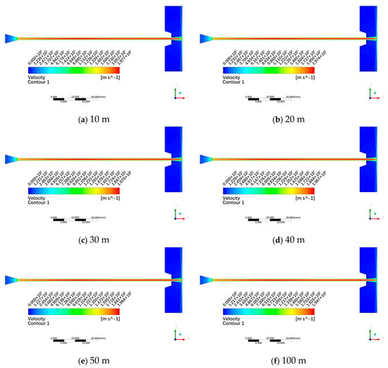
Figure 14.
Velocity contour plots under different submergence depths.
Figure 15 illustrates the variation curve of axial-jet velocity along the jet centerline from the nozzle exit to the target wall. Despite minor reductions in nozzle exit velocity at greater depths, all six curves exhibit close proximity. Consequently, the impact of submergence depths below 100 m on the cutting performance of abrasive water jets can be disregarded. Wei X utilized Large-Eddy simulation (LES) to investigate the flow field of submerged water jets at depths up to 40 m [33]. Within 40 m, the impact of submergence depth on flow-field characteristics—such as jet attenuation, vortex distribution, and dynamic pressure distribution—is negligible, which aligns well with the findings of this study.
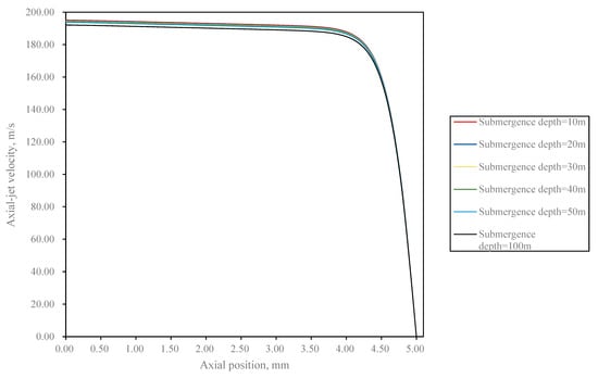
Figure 15.
Variation curve of axial-jet velocity along the jet centerline from the nozzle exit to the target wall under different submergence depths.
- (2)
- Pressure Distribution
Figure 16 illustrates the pressure contour plots under different submergence depths. The pressure distributions across different submergence depths show remarkable similarity, with no significant distinctions observed. Notably, the jet pressure profile exhibits an identical pattern to that documented in Figure 10 for different standoff-distance models. Jet pressure peaks at the nozzle inlet and decreases progressively along the jet direction within the nozzle. Upon exiting the nozzle, the jet pressure approaches ambient levels. When impinging on the wall surface, rapid decay of axial-jet velocity generates significant stagnation pressure. Figure 17 illustrates the variation curve of pressure along the centerline under different submergence depths. These curves exhibit striking similarity: near the nozzle exit, pressure approaches ambient levels (at submergence depths of 10 m, 20 m, 30 m, 40 m, 50 m, and 100 m, the jet pressure at x = 0 mm on the axis was 0.180049 MPa, 0.2778473 MPa, 0.375646 MPa, 0.473447 MPa, 0.571254 MPa, and 1.060258 MPa, respectively), while stagnation pressure magnitudes adjacent to the wall remain similar across all submerged conditions (at submergence depths of 10 m, 20 m, 30 m, 40 m, 50 m, and 100 m, the jet pressure at x = 5 mm on the axis was 18.513368 MPa, 18.548792 MPa, 18.584218 MPa, 18.619646 MPa, 18.655084 MPa, and 18.832352 MPa, respectively). That is, the stagnation pressure increases slightly with greater submergence depth. However, the variation patterns of jet pressure remain similar across different depths.
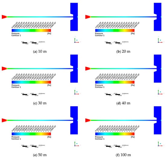
Figure 16.
Pressure contour plots under different submergence depths.
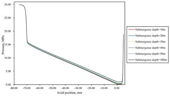
Figure 17.
Variation curve of pressure along the centerline under different submergence depths.
- (3)
- Motion behavior of abrasive particles
Figure 18 presents particle trajectory plots under different submergence depths, with twenty randomly selected particles for each condition. As observed in the figure, the trajectories of abrasive particles remain largely identical across different submergence depths. The abrasive particle velocity variation pattern is the same as the general rule of the velocity variations in abrasive particles for different standoff-distance models and exhibits a similar trend to that at a 5 mm standoff distance, shown in Figure 12b. Namely, distinct rebound phenomena are observed, and none of the rebounding abrasive particles return to the nozzle, and the rebound velocity of abrasive particles remains relatively low. In other words, the submergence depth has minimal impact on abrasive particle trajectories.

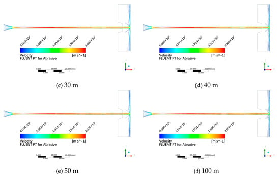
Figure 18.
Particle trajectory plots under different submergence depths.
Figure 19 presents the particle velocity versus trajectory length curves under different submergence depths. As observed in the figure, the particle velocity profiles at different submergence depths match those in Figure 13b for a 5 mm standoff distance. Namely, the acceleration characteristics of abrasive particles are generally favorable, with only a small fraction of abrasive particles decelerating significantly before reaching either the target wall or nozzle exit. Most particles maintain high velocities from the nozzle exit to the target wall, which enhances the cutting effectiveness of submerged pre-mixed abrasive water jets. In other words, the submergence depth has minimal impact on the velocity variation characteristics of abrasive particles.
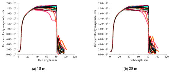
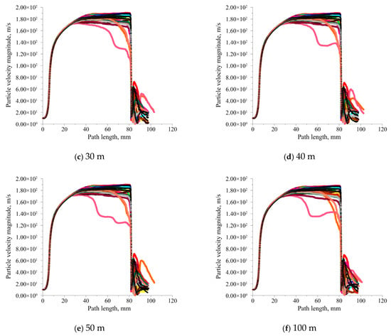
Figure 19.
Particle velocity versus trajectory length curves under different submergence depths.
5. Conclusions
- (1)
- A “water cushion layer” forms when the submerged pre-mixed abrasive water jet (SPAWJ) impinges on a wall, which is detrimental to the erosive action of abrasive particles on the target material. Tilting the nozzle appropriately facilitates the rapid dispersion of water and abrasive particles, which is beneficial for cutting.
- (2)
- The axial-jet velocity increases rapidly in the convergent section of the nozzle, continues to accelerate over a certain distance after entering the cylindrical section, reaches its maximum value inside the nozzle, and then decelerates to a steady value before exiting the nozzle. In addition, the standoff distance has minimal impact on the flow-field characteristic inside the nozzle.
- (3)
- In the external flow field of nozzles, beyond the length of the jet core section along the centerline, the decay rate of the axial-jet velocity decreases more slowly with increasing axial distance.
- (4)
- Jet pressure peaks at the nozzle inlet and decreases progressively along the jet direction within the nozzle. Upon exiting the nozzle, the jet pressure approaches ambient levels. When impinging on the wall surface, rapid decay of axial-jet velocity generates significant stagnation pressure. The stagnation pressure at the centerline of the submerged pre-mixed abrasive water jet decreases with increasing standoff distance for different standoff-distance models.
- (5)
- Considering the effects of standoff distance on jet velocity and abrasive particle dynamics, a standoff distance of 5 mm is determined to be optimal for submerged pre-mixed abrasive-water-jet (SPAWJ) pipe-cutting operations.
- (6)
- When the submergence depth is less than 100 m, its effect on the flow-field characteristics (such as velocity distribution, pressure variation pattern, and abrasive particle dynamics) of a submerged pre-mixed abrasive water jet (SPAWJ) impinging on a wall surface remains minimal. Consequently, for underwater oil pipelines operating at depths not exceeding 100 m, the influence of submergence depth can be disregarded during cutting operations.
Author Contributions
Conceptualization, J.G.; Methodology, S.H.; Formal analysis, J.D. and P.Z.; Resources, S.C.; Writing—original draft, J.W.; Project administration, J.X. All authors have read and agreed to the published version of the manuscript.
Funding
This research was funded by the Natural Science Foundation of China (52302422 and 52272338), the Natural Science Foundation of Chongqing, China (CSTB2024NSCQ-QCXMX0080 and CSTB2024NSCQ-MSX1039), and Science and Technology Research Program of Chongqing Municipal Education Commission (Grant No. KJQN202412903).
Data Availability Statement
The original contributions presented in this study are included in the article. Further inquiries can be directed to the corresponding author.
Conflicts of Interest
The authors declare no conflict of interest.
References
- Wu, T.; Chen, Y.; Deng, Z.; Shen, L.; Xie, Z.; Liu, Y.; Zhu, S.; Liu, C.; Li, Y. Oil pipeline leakage monitoring developments in China. J. Pipeline Sci. Eng. 2023, 3, 100129. [Google Scholar] [CrossRef]
- Wu, Y. Research on High Pressure Abrasive Jet Underwater Cutting Technology. Master’s Thesis, Harbin Engineering University, Harbin, China, 2023. [Google Scholar] [CrossRef]
- Zhou, C.; Jiao, X.; Gao, H. Abrasive water jet technology and its application to cutting of underwater structure. Weld. Join. 2015, 5, 1–6. [Google Scholar]
- Yan, H.; Shi, S.; Liu, J.; Xu, L. Risk assessment of cutting methods for underwater structures removal of abandoned platform. China Offshore Platf. 2021, 36, 26–30. [Google Scholar] [CrossRef]
- Deng, S.; Dai, F.; Pang, C.; Leng, X.; Sun, G.; Wang, Y. Discussion on safety application of abrasive water jet cutting technology in coal mine production. Min. Saf. Environ. Prot. 2023, 50, 115–118. [Google Scholar] [CrossRef]
- Qiang, C. Study on Cutting Mechanism and Performance Optimization of Tungsten Steel by Liquid Nitrogen Assisted Abrasive Water Jet. Master’s Thesis, China University of Mining and Technology, Xuzhou, China, 2023. [Google Scholar]
- Deng, L. Research on Underwater Cutting Performance of High-Pressure Abrasive Jet System. Ph.D. Thesis, Harbin Engineering University, Harbin, China, 2024. [Google Scholar] [CrossRef]
- Li, Z.; Li, B.; Wang, G.; Qiao, Z.; Sun, H.; Lei, Z. Global simulation of post-mixed abrasive water jet based on abrasive kinetic energy and concentration. J. Vib. Shock. 2023, 44, 76–85. [Google Scholar] [CrossRef]
- Zhao, W. Study on the System Pressure Characteristics of ASJ and Its Control Technology. Ph.D. Thesis, China University of Mining and Technology, Xuzhou, China, 2021. [Google Scholar]
- Xu, Q. Numerical Simulation and Experimental Research on External Flow Field of Abrasive Water Suspension Jet. Master’s Thesis, China University of Mining and Technology, Xuzhou, China, 2019. [Google Scholar]
- Li, L. Two phase numerical simulation of continuous abrasive water jet system based on EDEM. IOP Conf. Ser. Earth Environ. Sci. 2020, 546, 042055. [Google Scholar] [CrossRef]
- Tang, J.; Zhang, J.; Liu, W.; Chen, C.; Zhang, H.; Cui, J. Two-way coupled CFD-DEM model of a pre-mixed abrasive water jet and its application to the investigation of abrasive motion characteristics. Powder Technol. Int. J. Sci. Technol. Wet Dry Part. Syst. 2024, 438, 119650. [Google Scholar] [CrossRef]
- Chen, C. Study on Energy Distribution Characteristics and Transfer Mechanism of Pre-Mixed Abrasive Jet. Ph.D. Thesis, Chongqing University, Chongqing, China, 2024. [Google Scholar] [CrossRef]
- Li, L. Study on the Microscopic Failure Mechanism of Abrasive Suspension Water Jet Cutting Carbon Fiber Reinforced Plastics and Optimization of Cutting Quality. Ph.D. Thesis, China University of Mining and Technology, Xuzhou, China, 2024. [Google Scholar] [CrossRef]
- Wang, X.; Ge, Z.; Liu, W.; Ge, R.; Wang, M.; Ge, B. Experimental Study on Rock-Breaking Mechanism of Submerged Abrasive Jet Assisted by an Air Sheath. Rock Mech. Rock Eng. 2025, 1–13. [Google Scholar] [CrossRef]
- Wang, G.; Yao, S.; Chi, Y.; Zhang, C.; Wang, N.; Chen, Y.; Lu, R.; Li, Z.; Zhang, X. Improvement of titanium alloy TA19 fatigue life by submerged abrasive waterjet peening: Correlation of its process parameters with surface integrity and fatigue performance. Chin. J. Aeronaut. 2024, 37, 377–390. [Google Scholar] [CrossRef]
- Ravi, R.R.; Srinivasu, D. An experimental investigation into the influence of water column height in submerged mode of abrasive waterjet trepanning on the hole quality. J. Manuf. Process. 2024, 117, 170–192. [Google Scholar] [CrossRef]
- Zeng, S. Study on the Characteristics of Flow Field Inside and Outside the Nozzle of High Pressure Abrasive Water Jet Under Submerged Conditions. Master’s Thesis, Chongqing Jiaotong University, Chongqing, China, 2018. [Google Scholar]
- Wang, C.; Shen, Y.; Liu, Z.; Zhao, Y.; Zhu, Y. Numerical simulation of straight cone nozzle abrasive water jets submerged. J. Daqing Pet. Inst. 2011, 35, 51–54. [Google Scholar] [CrossRef]
- Huang, N.; Xue, S.; Chang, X.; Pang, J. Research on Under-water Cutting Technology of Abrasive Water Jet with CFD. Hydraul. Pneum. Seals 2011, 11, 22–25. [Google Scholar]
- Cui, H. Numerical Simulation and Its Applications on Flow Field of Liquid-Solid Two-Phase Flow for Pre-Mixed Abrasive Water Jet. Master’s Thesis, Liaoning Technical University, Fuxin, China, 2008. [Google Scholar]
- Wang, J.; Zhang, S. Under-water cutting explosive equipment technology of pre-mixed abrasive water jet. J. PLA Univ. Sci. Technol. (Nat. Sci. Ed.) 2011, 12, 393–396. [Google Scholar]
- Qiang, Z.; Wu, M.; Miao, X.; Sawhney, R. CFD research on particle movement and nozzle wear in the abrasive water jet cutting head. Int. J. Adv. Manuf. Technol. 2018, 95, 4091–4100. [Google Scholar] [CrossRef]
- Chen, Z.; Heng, Y.; Xiong, P.; Jiang, Q.; Luo, X.; Shen, Q. Influence of particle properties on the performance and wear of centrifugal pumps based on CFD-DPM. J. Xihua Univ. (Nat. Sci. Ed.) 2024, 43, 87–96. [Google Scholar] [CrossRef]
- Yang, S.; Huang, D.; Zeng, S. Influence of environmental flow velocity on the flow field characteristics of underwater abrasive water jet. J. Vib. Shock. 2019, 38, 139–152. [Google Scholar] [CrossRef]
- Zhu, H.; Lin, Y.; Xie, L. Fluent 12: Fluid Analysis and Engineering Simulation; Tsinghua University Press: Beijing, China, 2011; pp. 179–188. [Google Scholar]
- Guan, J.; Deng, S.; Duan, J.; Chen, X.; Yu, Y. Analysis of rule influences of geometric structural parameters on wear of abrasive water jet nozzle. Mach. Tool Hydraul. 2017, 45, 5. [Google Scholar]
- Yang, H. Research on Numerical Simulation Method and Vortex Control Technology for Wall Turbulence of Hydraulic Torque Converter. Ph.D. Thesis, Jilin University, Jilin, China, 2024. [Google Scholar] [CrossRef]
- Zhang, L. Study on Numerical Calculation and Internal Flow Characteristics of Submerged Impinging Jet. Master’s Thesis, Jiangsu University, Zhenjiang, China, 2022. [Google Scholar] [CrossRef]
- Dai, T. Numerical Simulation and Equipment Design of Self-excited Oscillation Cavitation. Master’s Thesis, China Three Gorges University, Yichang, China, 2024. [Google Scholar] [CrossRef]
- Yu, J.; Liu, J.; Wang, G.; Luo, S.; Wang, J. Correction of Realizable k-ε model for high pressure submerged water jets. Sci. Technol. Eng. 2021, 12, 5024–5030. [Google Scholar] [CrossRef]
- Lin, X.; Lu, Y.; Tang, J.; Zhang, W.; Cheng, Y. Numerical simulation of abrasive particles acceleration process in pre-mixed abrasive water jet. J. Vib. Shock. 2015, 34, 19–24. [Google Scholar] [CrossRef]
- Wei, X. The Study on Flow Field Characteristics of High Pressure Water Jet Under Submerged Condition. Master’s Thesis, Chongqing Jiaotong University, Chongqing, China, 2017. [Google Scholar]
Disclaimer/Publisher’s Note: The statements, opinions and data contained in all publications are solely those of the individual author(s) and contributor(s) and not of MDPI and/or the editor(s). MDPI and/or the editor(s) disclaim responsibility for any injury to people or property resulting from any ideas, methods, instructions or products referred to in the content. |
© 2025 by the authors. Licensee MDPI, Basel, Switzerland. This article is an open access article distributed under the terms and conditions of the Creative Commons Attribution (CC BY) license (https://creativecommons.org/licenses/by/4.0/).