Abstract
Spontaneous liquid–liquid capillary imbibition in axially varying capillaries is central to petroleum engineering applications such as water-driven enhanced oil recovery, where the dynamic contact angle (DCA) governs interfacial motion. We extend the classical Lucas–Washburn (LW) formulation to account for axial variations in the hydraulic radius, early-time inertia, and viscous dissipation in the displaced non-wetting phase. In parallel, we develop a cascaded multicomponent Shan–Chen lattice Boltzmann model (LBM) that resolves the in situ evolution of the DCA and simulate imbibition in three area-matched geometries: convergent conical, divergent conical, and parabolic. The axial profile is shown to control both the imbibition rate and the DCA. For a viscosity-matched binary fluid, the temporal variation in the DCA is set by the local contraction rate: the DCA decreases as the capillary widens and increases as it narrows. Stronger intrinsic wettability enlarges the discrepancy between the DCA and the static contact angle (SCA). Moreover, at fixed non-wetting-phase viscosity, decreasing the wetting/non-wetting viscosity ratio reduces the imbibition rate and drives the DCA toward the SCA. Predictions from the extended LW equation that neglect DCA exhibit systematic deviations from LBM results, whereas supplying the time-resolved DCA yields close quantitative agreement across all geometries. These findings identify the DCA as a critical state variable for reduced-order prediction of imbibition in axially varying capillaries and inform the design of enhanced-oil-recovery and microfluidic systems.
1. Introduction
The liquid–liquid spontaneous capillary imbibition is a common physical phenomenon in nature and has critical study value in industrial fields such as oil development and enhanced recovery [1,2,3,4,5]. To describe the correlation between meniscus position and time, Lucas–Washburn established the well-known theory of imbibition within a circular capillary (LW equation) based on the Poiseuille flow law, which considers the displacement of the meniscus to be proportional to the square root of time [6,7]. However, the LW equation is subject to certain limitations. It assumes a constant contact angle of the meniscus and neglects early inertial forces, resulting in a significantly higher predicted imbibition length than experimental results [8,9,10,11]. Moreover, it presupposes a uniform capillary radius and cannot directly be applicable to predict imbibition processes in intricate pores with non-uniform axial radius in reservoir rocks [12,13,14,15]. Furthermore, predicting the imbibition process of wetting and nonwetting fluids with similar viscosities is challenging. This is due to the assumption that displaced fluids behave as a gas, which neglects their viscous effects [16].
Researchers have extensively investigated the spontaneous imbibition process in capillaries with various cross-sectional shapes to address the above issues through theoretical analysis, experiments, and numerical simulations. In experimental terms, Mumley [17] conducted experiments to investigate the capillary rise in glycerol–water systems with varying viscosities in circular capillaries. Based on these findings, the original LW equation has been modified by considering the viscous force contribution of the non-wetting hydrocarbon-like phase (NW), making it applicable for predicting the imbibition process in liquid–liquid systems. In addition, dynamical changes in the contact angle of the meniscus have been observed during imbibition. Subsequently, Fermigier [18] used experiments to measure the dynamic contact angles (DCA) of silicone oil-air and silicone oil-glycerol systems during imbibition. The results show that the dynamic variability properties of the meniscus are more significant in the liquid–liquid system. Walls [19] conducted experimental and theoretical investigations on the capillary rise in immiscible Newtonian aqueous–hydrocarbon systems with controlled viscosity ratios. They showed how the characteristic behavior of the LW equation is modified when the viscosity of the displaced non-wetting phase is comparable to or higher than that of the invading wetting phase. André [20] investigated liquid–liquid capillary replacement in horizontal geometry and found that conventional slowing-down dynamics occur during imbibition when the viscosity of the wetting fluid is much larger than that of the non-wetting fluid. A linear relationship between imbibition length and time is observed when their viscosities are equal. However, acceleration dynamic occurs when the viscosity of the wetting fluid is significantly lower than that of the non-wetting fluid.
Yet, the experiments above were only conducted in capillaries with regular circular cross-sections. There have been few reports on liquid–liquid imbibition experiments in capillaries with varying axial cross-sections. Fortunately, researchers have carried out numerous gas–liquid imbibition experiments and theoretical modeling on liquid–liquid imbibition in irregular capillaries, which can serve as a reliable reference. Reyssat [21] investigated the silicone oil-air imbibition process in a monotonic dispersion conical capillary based on experimental and theoretical analysis. He concluded that the relationship between imbibition length and time still conforms to the LW equation in a short period. However, over an extended duration, variations in the axial width of the capillary cause deviation from the LW equation and exhibit a power relationship related to capillary geometry. Wang [22] developed a model for liquid imbibition and flow in capillaries of sinusoidal varying cross-sections and believed that the diminished wettability amplifies the effect of capillary geometry on permeation imbibition. For a convergent capillary with a monotonous power-law relationship between its radius and length, Gorce [23] found that imbibition occurs faster in capillaries with a power law relationship between the radius and axial position than in constant-radius capillaries when non-wetting fluid viscosity is negligible. More recently, Lei [24] developed an analytical model involving inertia, viscosity, and gravity to describe capillary rise dynamics in a circular tube with an undulated inner wall and oriented at an arbitrary angle. Shobeiri [25] proposes a novel formulation of capillarity, which geometrically extends the Bosanquet equation to irregular geometries, taking the effect of inertia and the dynamic contact angle into account. They emphasize the longer continuation of the inertial forces acting in the imbibition process in irregular capillaries. However, the contribution of non-wetting fluid viscosity force needs to be addressed in all the above models, and the prediction is relatively poor for liquid–liquid imbibition with a finite viscosity ratio. To address the above issues, Budaraju [26] extended Reyssat’s model by considering the contribution of non-wetting fluid viscosity. He investigated the imbibition process in monotonic dispersion capillaries with power-shaped cross-section, and the results showed that the imbibition length satisfies a linear relationship with time in the early stages of imbibition due to the contribution of non-wetting fluid viscosity. In contrast, at long times, the imbibition dynamics depend upon the shape of the capillary. Salama [27] developed an imbibition model that considers the viscosity of both fluids and capillary cross-section shape. Based on this model, he believed that when the radius ratio between the entrance and exit of the capillary equals the viscosity ratio between the wetting and non-wetting fluid, the speed of the meniscus assumes a constant value, whereas for a radius ratio more minor than the viscosity ratio, there is a continuous decrease in meniscus velocity along the tube; conversely, if the radius ratio exceeds the viscosity ratio, then meniscus velocity increases along the said tube. However, he assumed that the contact angle of the meniscus is a SCA that limits the application of the model in short distances due to the dominant role of the DCA.
Compared with theoretical and experimental approaches, numerical simulation methods can demonstrate more intuitively the real-time changes in the meniscus during imbibition. Due to its numerical stability and versatility, the lattice Boltzmann method (LBM) is a powerful technique for simulating two-phase transport processes involving interfacial dynamics [28]. The LBM is commonly used to simulate include two-phase flow models based on diffusion interfaces (color gradient model [29,30], pseudopotential model [31], free energy model [32,33], phase field model [34], and free surface flow model based on sharp interfaces [35]). In particular, the Shan–Chen model has a clear physical background and is widely used to simulate gas–liquid capillary and liquid–liquid capillary imbibition [36]. Chibbaro [37] employed the multicomponent Shan–Chen model to simulate the imbibition process of a two-phase fluid with a density ratio and viscosity ratio of 1 in straight capillaries with varying degrees of wettability. They found that increasing the capillary width resulted in a more pronounced DCA of the meniscus in their simulations. Budaraju [26] used the multicomponent Shan–Chen model to simulate capillary imbibition with power dispersion and found that the DCA is the leading cause of the discrepancy between simulation results and quasi-static theory.
However, the original multicomponent Shan–Chen model has limitations, such as the density and viscosity ratios cannot be adjusted independently. The existence of non-physical density layers in the virtual density-based contact angle scheme will have some influence on the imbibition process [36]. To comprehensively investigate the impact of axial capillary shape on spontaneous imbibition in liquid–liquid flows with finite viscosity ratio, we have extended conventional LW equations by incorporating inertial forces, axial capillary shape, and nonwetting fluid viscosity. We have also developed a multicomponent Shan–Chen model independent of density and viscosity ratios and surface tension. Simultaneously, we mitigate the emergence of virtual density layers by implementing a novel flow-solid interaction force scheme. The established LBM is utilized to simulate the spontaneous imbibition of liquid–liquid flows in capillaries with varying axial geometries and to capture real-time DCAs. We also investigate the impact of different wettability and viscosity ratios on the DCA and imbibition length during this process.
2. Materials and Methods
2.1. Extended Lucas–Washburn Equation
For an open 2D microchannel in a horizontal orientation, the Newtonian equation of motion is expressed based on the force balance on the two liquid columns in the microchannel, which can be written as [27,38]
where σ is the interfacial tension, n is normal to the boundary unit vector, t is the unit vector normal to the contact line in the plane tangent to the interface, η is the viscous stress tensor, and U denotes the velocity vector of the fluid crossing the boundary. The left-hand side of Equation (1) represents the inertia of the fluid, while the right-hand side of Equation (1) represents the sum of external forces during imbibing. To simplify the governing equations, we use the average velocity of the meniscus as an approximation instead of the overall velocity of the curved fluid surface, which is expressed as U = dl(t)/dt, with l(t) denoting the imbibition length at time t. Based on this condition, the left-hand side in Equation (1) can be further expanded as
where , A(0), A(L), and A(l) denote the cross-section areas at the inlet, exit, and the location of the meniscus, respectively. L represents the length of the microchannel, l is the imbibition length of the wetting fluid, and h(l) is the capillary width at the location of the meniscus; ρw and ρnw are the densities of the wetting and non-wetting fluids, respectively. Expanding the simplification further, we can obtain the following:
In the right-hand side of Equation (1), ∑F = Fdrive + Fdrag, Fdrive, and Fdrag are driving and drag forces during imbibition. Fdrive is dominated by capillary pressure and Fdrag is dominated by a viscous drag force, including wetting phase viscous drag force Fw, drag and non-wetting phase viscous drag force Fnw, drag. To determine the mathematical expression for the viscous drag, one must assume that the imbibition process satisfies the Poiseuille flow law (fully developed flow). The fully developed Poiseuille approximation is adopted as a tractable closure for viscous losses; its limitations at early times (inertia-affected) and in rapidly varying geometries are acknowledged. In this case, the driving and drag terms of the imbibition process can be expressed [25,26]
where μw and μnw are the dynamic viscosities of wetting and non-wetting fluids, respectively. b is the depth of the capillary at the location of the meniscus; θ* = θ − β, θ is the apparent contact angle; and represents the slope of the capillary at the site of the meniscus. For axially varying walls, the effective contact angle θ* = θ − β projects capillary forcing onto the axial direction via the local wall inclination . Furthermore, the governing equation of the dynamics of liquid–liquid spontaneous imbibition can be derived from the left and right ends of Equation (1), which is expressed as
In Equation (5), each term (from left to right) represents the capillary force, viscous force, and inertial force, respectively. Considering that Equation (5) is a typical second-order, constant coefficient, nonlinear, ordinary differential equation, it is difficult to determine the general solution of this problem directly by mathematical methods. Fortunately, it can be solved numerically by linearly interpolating the nonlinear integral functions given in Equation (5), thereby converting the nonlinear integrodifferential equation to a second-order, nonlinear, ordinary differential equation (ODE) whose coefficients are known at any l(t). Regarding the solution procedure, the nonlinear integro-differential form (Equation (5)) is evaluated by computing integral terms at each time step (composite quadrature) and advancing the resulting ODE with a fourth-order Runge–Kutta scheme; no linear interpolation of nonlinear integrals is used, and step-doubling confirms stability. The resulting nonlinearity is then solved by the Runge–Kutta algorithm with two specific marginal conditions: t = 0, l = 0; t = 0, dl/dt = 0 [25]. Note that when h(z) = h0, and neglecting the effect of inertial forces, Equation (5) can be simplified to the conventional LW equation for straight capillary, which can be written as
As a result, we can completely solve the dynamics, which yields
Under the above assumption, this solution is valid, irrespective of the relative values of μw and μnw. Moreover, in the limit μw = μnw, this solution approaches the simple form of
2.2. Modified Shan–Chen Multicomponent Multiphase Model
In this work, we employed the cascaded lattice Boltzmann method with a central moment collision operator to improve the numerical stability of the model, which can be expressed as [39]
where is the αth component density distribution function; and in our case, the subscripts for non-wetting and wetting fluid components are denoted as α = 1, α = 2, respectively. x is the lattice position, t is the lattice time, Δt is the time step, and generally, Δt = 1. For the two-dimensional, nine-velocity lattice (D2Q9) model, the discrete velocity is given by
where i = 0, 1, 2, … 8 and the superscript T is the transposition symbol. In Equation (9), S is a diagonal matrix, M is adopted to transform the distribution functions () to their raw moments (), and N is used to shift the raw moments into the central moments () as follows:
To build the cascaded lattice Boltzmann method (CLBM), we define the raw and central moments as follows:
where ux and uy denote the x and y directional velocity components of the macroscopic velocity u. Then, the specific form of the raw and central moments can be given by
In Equation (4), the first three moments represent the component density and momentum, and the middle and last three stand for the viscous stress and high-order non-hydrodynamic moments, respectively. Through Equation (3), the transformation matrices M and N can be written as [40]
In Equation (1), and are the equilibrium distribution function and the force term, and by using the transformation matrices M and N, the equilibrium central moments and the forcing terms in the central moment space can be obtained as follows:
where Fα = [Fα, x, Fα, y] is the force which includes fluid–fluid forces, fluid–solid forces, and other body forces, ρα is the macroscopic density. The macroscopic density ρα and the macroscopic velocity u can be expressed as [41]
In this paper, the relaxation matrix S consists of nine diagonal matrices, which can be expressed as
Since mass conservation, we set s0 = s1 = s4 = sb = 1.0 in the following, and the other relaxation rates are set as s3 = (16 − 8s2)/(8 − s2). When the viscosity of the two components is different, to make the system relaxation time transition smoothly at the gas–liquid interface, the system relaxation rate is defined as follows:
where cs is the lattice sound speed; ν represents kinematic viscosity, specifically, ; and τ denotes relaxation time. The total force on the αth component, including fluid–fluid forces Ff-f, fluid–solid forces Ff-s, and other body forces Fb. In the model, the Ff-f shows a repulsive effect and is used for controlling phase separation and interfacial tension, which can be expressed as
where ψ is the pseudopotential of the fluid component. In this work, we set ψ1 = ρ1 and ψ2 = ρ2; G12 and G21 denotes the fluid–fluid cohesion strength, and, in general, G12 = G21. It is worth noting that only the inter-component interaction force is considered in this work, while the intra-component interaction force is neglected. The fluid–solid forces (Ff-s) are used to implement contact angle modeling. We adopt the improved virtual solid density scheme, which can be written as [42]
where Sα is the virtual solid pseudopotential for the solid boundaries, is the parameter controlling the strength of fluid–solid interaction, and in the model, the Gα,s in Equation (23) is set equal to G12. For the improved virtual solid density scheme, the virtual solid pseudopotential of the solid boundaries can be written as
where ϕ(x) is the switch function, which is 1 for a fluid node and 0 for a solid node. is the virtual solid pseudopotential; it is defined by using the averaged density of its fluid neighbors, which can be expressed as
where χα is a factor that controlled the wettability; for the different fluid components, it can be chosen as
For ξ = 0, the solid surface is naturally wetting for both fluid components; for ξ < 0, the solid surface is hydrophobic for the fluid component 1; and when ξ > 0, the solid surface is hydrophilic for the fluid component 1. We compute the virtual solid density using a two-dimensional, 25-velocity lattice (D2Q25) that includes all neighbors in the first and second belts [5,42] as follows:
When the system is at a steady state, the total pressure of the system Ptotal can be expressed as
3. Results and Discussion
In our previous study [38], we systematically determined the appropriate parameters for the adopted MCMP Shan–Chen model through a series of preliminary tests, including miscibility, interfacial tension, and static contact angle measurements, as summarized in Table 1. In addition to the preliminary tests (miscibility, interfacial tension, and static contact angle) summarized in Table 1, the present LBM framework has been quantitatively benchmarked against established cases—including spontaneous imbibition in straight capillaries governed by the Lucas–Washburn law—and exhibits good agreement. We also confirmed that the improved virtual solid density contact-angle scheme suppresses unphysical wall-adjacent density layers by comparing near-wall density profiles with and without this treatment [43]. It should be noted that lattice units (lu) will be utilized in subsequent studies, unless otherwise specified.

Table 1.
Properties of wetting and non-wetting phases in lattice and physical units.
3.1. Effect of Axial Capillary Shape
This section has designed three types of capillaries with different axial shapes to investigate the liquid–liquid spontaneous imbibition process. Their details can be found in Table 2. To achieve the above objective, we initially establish a lattice region of 601 × 101 and select a capillary with different axial shapes at 150 ≤ x ≤ 450. The bounce-back boundary condition is applied to the capillary walls, while the remaining part of the capillary is set as a periodic boundary. It is worth noting that the areas of the five capillaries are equal, with only variations in axial shape. To ensure that enough wetting fluids enter the capillary, we initialize the wetting fluid at positions x ≤ 150 and x ≥ 550 while initializing the remaining space as non-wetting fluid. The initial contact angle of the wall is prescribed as θ0 = 45° (ξ = −0.605), and the viscosity ratio between the wetting and non-wetting fluids is set to M = 1.
Table 2.
The axial shape of the capillary used for the simulation.
Figure 1a illustrates the liquid–liquid spontaneous imbibition process in a monotonically divergent conical capillary where h(z) = 20 + z/15. As the imbibition length increases, the capillary width gradually increases, leading to a gradual decrease in the capillary force. After a certain period (e.g., t = 42,000), the imbibition rate of Case A exhibits a marked deceleration. The method was employed to capture the θd during the imbibition in Case A, as shown in Figure 1b. The θd in Case A has complex behavior due to the variation in the axial width. The liquid–liquid interface is extracted from the iso-density contour at . Within a 5–10-node window near the wall, 7–11 interface points are collected and fitted with a circular arc (least-squares). The DCA equals the angle between the tangent of the fitted arc at the wall intersection and the local wall tangent. Uncertainty is estimated by varying the window size and point count; typical variations are within a few degrees at the reported resolution. Apparent jumps originate from the staircase representation of curved walls on the Cartesian lattice. We apply temporal smoothing and observe that the effect diminishes with grid refinement. Smoothed values are used to close the LW model, avoiding inclusion of lattice-induced spikes as physical input. On the other hand, the staircase approximation inherent to Cartesian grids can be considered as a form of capillary roughness, which is consistent with actual reservoir conditions. Additionally, a sudden alteration in the value of θd can be observed. This is due to the limited structured mesh used in our LBM. It fails to model the continuous variation in axial capillary width realistically and instead relies on a staircase approximation to characterize such variations [44]. To provide a more comprehensive explanation of the numerical variation in θd, we give the evolution of the meniscus shape within two adjacent staircases. A gradual increase in the curvature radius of the meniscus located at the left-hand side of the stairway corner is observable, resulting in a corresponding progressive augmentation of θd. When the meniscus encounters a staircase, there is a jump in the contact line position, leading to an additional increase in θd. As the meniscus enters the right side of the staircase, its radius of curvature gradually decreases, and θd accordingly decreases. The presence of multiple staircases results in multiple jumps in θd during imbibition. In general, as the axial width of the capillary increases, it also leads to a decrease in the difference of θd − θ0, and when t = 72,000, θd = 49.4°. This phenomenon can also be reasonably explained from the perspective of imbibition rate, as shown in Figure 1c, where the relationship between imbibition length and time exhibits a sublinear evolution (l∝tn, n < 1) rather than a linear one (n = 1). This suggests that as the axial width of the capillary gradually increases, the imbibition velocity gradually decreases, resulting in a decreasing trend for θd. For capillaries with an axial variation, the LW equation predicts significantly longer imbibition lengths than the LBM due to its failure to account for DCA. By incorporating the DCA data in Figure 1b to correct Equation (5), we observe excellent agreement between Equation (5) and LBM.
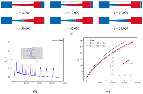
Figure 1.
(a) Liquid–liquid spontaneous imbibition process at different time steps in the monotonically divergent conical capillary. (b) Time evolution of contact angle during liquid–liquid spontaneous imbibition. (c) Theoretical imbibition lengths with and without considering the dynamic contact angle with LBM results.
Figure 2a illustrates the imbibition process in a monotonically convergent conical capillary (case B), where h(z) = 40 − z/15 and the capillary exhibits a gradual decrease in axial width. Compared to the previous two cases, the meniscus in Case B moved at a significantly lower velocity in the initial stage. On the one hand, the capillary of Case B boasts a maximum inlet width and thus requires an increased draw into wetting fluid during the initial imbibition stage. On the other hand, the meniscus advances slowly in this initial stage due to its wider inlet and weaker capillary force. However, the meniscus displacement rate can be observed, as the imbibition time increases and the axial width of the capillary decreases accordingly. In Figure 2b, we present the temporal evolution of the θd. As the axial width gradually decreases, its imbibition rate gradually increases, exhibiting an overall increasing trend in θd. However, due to the approximation of the staircase shape, there is still a discontinuity in θd, and unlike Case B, it exhibits a downward jump in this scenario. Specifically, we present the time evolution of the meniscus profile between two staircases. At the left of the staircase, the contact line of the meniscus moves faster while the midline moves slower, resulting in a decrease in θd. However, as the staircase is crossed, the velocity at the midline gradually increases, leading to an increase in θd. From a general perspective, the value of θd tends to increase as the axial width decreases, and when t = 71,700, θd = 55.7°, which exceeds the values obtained in the previous two cases. We can account for this phenomenon by considering the time-dependent evolution of the imbibition length. As illustrated in Figure 2c, the imbibition length exhibits a super-linear dependence on time (l∝tn, n > 1), resulting in a gradual increase in the imbibition rate and, consequently, an elevation of the θd. Similarly, the imbibition length predicted by the LW equation u based solely on static contact angle exhibits significant deviation from that of LBM. By incorporating real-time dynamic contact angle data from Figure 2b into the LW equation, we achieve a highly accurate prediction of imbibition length and more closely to LBM.
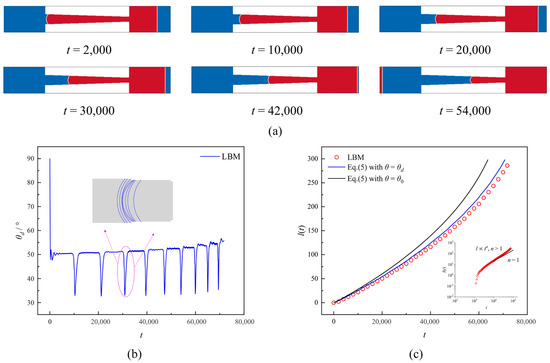
Figure 2.
(a) Liquid–liquid spontaneous imbibition process at different time steps in the monotonically convergent conical capillary. (b) Time evolution of contact angle during liquid–liquid spontaneous imbibition. (c) Theoretical imbibition length with and without considering the dynamic contact angle with LBM results.
In contrast to the previous two cases, the axial width of the parabolic capillary in case C (h(z) = 40 + (z2 − 300z)/1500) exhibits a non-monotonic axial width variation characterized by a progressive decrease to a minimum followed by a gradual increase. In Figure 3a, we present the spontaneous imbibition process inside the parabolic capillary. During the initial stage, the meniscus moves at a lower rate due to the larger capillary width. However, there is a difference in that the axial width of the capillary decreases more rapidly in case C, so it leads to a faster increase in imbibition rate compared to Case B. However, as the capillary width does not always decrease uniformly, a reduction to its minimum value results in a corresponding decrease in imbibition rate with increasing capillary width. This demonstrates that the velocity of imbibition does not vary monotonically but instead varies correspondingly with the axial shape of the capillary. Figure 3b shows the time evolution of the θd during imbibition. It can be seen that the evolution of θd in case C gathers the evolution patterns of the previous three cases. As the axial width decreases, θd typically exhibits an increasing trend with an abrupt local decrease. When the axial width remains constant, θd fundamentally remains unchanged. However, as the axial width increases, θd usually shows a decreasing trend with a local upward jump. The time evolution of the imbibition length in Figure 3c confirms that the imbibition rate in case C correlates with variations in axial capillary width. The imbibition length of the capillary exhibited a super-linear relationship with time as its axial width gradually decreased. At the same time, it displayed a sublinear relationship in the region where its axial width increased. Moreover, the predicted imbibition length from the LW equation, which ignores DCA effects, is inconsistent with LBM results. Similarly, by incorporating DCA data from Figure 3b, we have corrected Equation (5) to yield an imbibition length that closely matches LBM predictions.
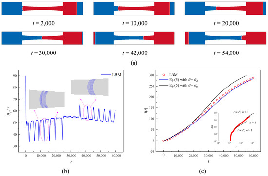
Figure 3.
(a) Liquid–liquid spontaneous imbibition process at different time steps in the parabolic capillary. (b) Time evolution of contact angle during liquid–liquid spontaneous imbibition. (c) Theoretical imbibition length with and without considering the dynamic contact angle with LBM results.
3.2. Effect of Wettability
As for the monotonically divergent conical capillary, the meniscus profiles in the capillary with monotonically increasing axial width at different time steps are shown in Figure 4a. The distance between meniscus profiles for different θ0 in Case A is obvious at the initial time, which indicates that the inertial forces contribute relatively weakly to the capillary width with a small size. The imbibition length increased the axial width of the capillary gradually dispersion, resulting in a decrease in imbibition velocity and an increase in distance between the three menisci. This was particularly evident in cases where θ0 = 45° and θ0 = 60°. To better explain this phenomenon, we give the real-time evolution of the DCA θd and the imbibition length for three different θ0 conditions, as shown in Figure 4b,c. One can observe that the θd shows a general trend of gradual decrease. Still, with the increase of θ0, the θd is influenced by the axial width increases, especially showing a more significant jump in value near the axial staircase. This will reduce the imbibition velocity to some extent, leading to a continuous increase in the distance between the menisci. When imbibition ended, the DCAs for the three cases were θd = 37.2° (θ0 = 30°), θd = 49.5° (θ0 = 45°), and θd = 61.6° (θ0 = 60°). Compared to Case A, the values of θd − θ0 are affected by increasingly dispersive axial widths and varying wettability resulting from decreasing imbibition rates. Meanwhile, as θ0 increases, the θd − θ0 value becomes smaller during imbibition, but the local jump in θd is also obvious. It should be noted that a relatively significant issue is that according to our simulation results, when θ0 tends to 90°, the local jump in θd is likely to exceed 90°, leading to the pinning of the contact line and forming a capillary valve effect. However, this is beyond the scope of this paper; instead, the reader is referred to the study by Liu et al. [45]. The imbibition length, which neglects the dynamic contact angle, differs from the LBM results, as depicted in Figure 4c. However, by incorporating the acquired dynamic contact angle data to rectify the Lucas–Washburn equation, a highly accurate prediction of imbibition length is achieved that closely matches LBM outcomes.
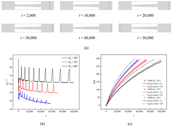
Figure 4.
(a) Liquid–liquid spontaneous imbibition process at different time steps for different wettability in the monotonically divergent conical capillary. (b) Time evolution of contact angle during liquid–liquid spontaneous imbibition for different wettability. (c) Theoretical imbibition length with and without considering the dynamic contact angle with LBM results for different wettability.
In Figure 5a, we give meniscus profiles in the monotonically convergent conical capillary for different θ0 values at different moments. The meniscus positions nearly coincide for different θ0 at t = 2000 due to the larger axial width at its entrance, where the inertial forces are significantly enhanced. As the imbibition length increases, the axial width of the capillary gradually decreases, resulting in a larger imbibition rate and an increase in the distance between the three menisci. We also illustrate the effect of imbibition velocity from the real-time evolution of the DCA θd and imbibition length, as shown in Figure 5b,c. Similarly, the time evolution pattern of the θd in capillaries with different θ0 shows similarity in that there is an overall upward trend. Still, there is a downward numerical jump in the values of the θd near the staircase. When imbibition ended, the ultimate DCAs for the three cases were θd = 45.9° (θ0 = 30°), θd = 55.7° (θ0 = 45°), and θd = 65.3° (θ0 = 60°). This further demonstrates that the θd-θ0 during imbibition will be significantly elevated with increased wettability and is positively correlated with the imbibition rate. The time evolution relationship of the imbibition length again confirms that the imbibition rate gradually increases as the axial width of the capillary decreases. We also compared the imbibition lengths calculated using the SCA/DCA data. We found that the imbibition lengths calculated using the DCA correction to the LW equation were closer to the LBM results.
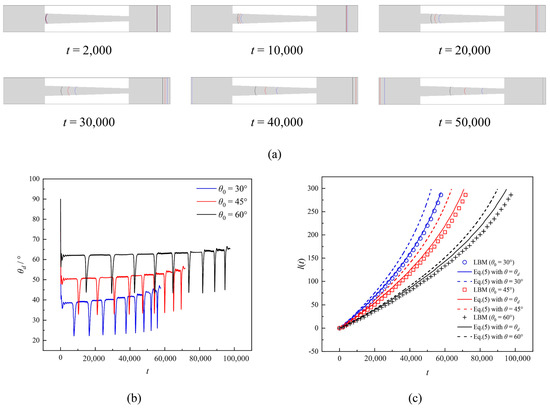
Figure 5.
(a) Liquid–liquid spontaneous imbibition process at different time steps for different wettability in the monotonically convergent conical capillary. (b) Time evolution of contact angle during liquid–liquid spontaneous imbibition for different wettability. (c) Theoretical imbibition length with and without considering the dynamic contact angle with LBM results for different wettability.
For the parabolic capillary with axial width that does not vary monotonically, the time evolution of their menisci is more complex, as shown in Figure 6a. It can be observed that the three meniscus positions are highly close to each other at t = 2000 due to the dominance of inertial forces. Subsequently, the imbibition rate gradually increased as the axial width of the capillary decreased, and the distance between the three menisci increased. Moreover, in the section where its axial width decreases, the meniscus distance between different values of θ0 is significantly smaller than in the area where its axial width increases monotonically. In Figure 6b, we show the time evolution of the DCA θd with different θ0. In general, as the axial width of the capillary gradually narrows, the imbibition velocity correspondingly accelerates, and the θd increases progressively; conversely, as the axial width of the capillary gradually widens, the θd decreases accordingly. Consistent with the previous results, the θd − θ0 exhibits a downward trend as θ0 diminishes during imbibition. The variation in the imbibition rate can also be obtained from the time evolution relation of the imbibition length, as shown in Figure 6c. For different values of θ0, the imbibition velocity gradually decreases after increasing to a constant value, which is not with the variation in the axial width of the parabolic capillary. The imbibition length predicted by the LW equation using the SCA data deviates significantly from the LBM, especially in the part of the space where the axial width of the capillary increases. At the same time, the imbibition length predicted by the LW equation after correcting the DCA is in good agreement with the LBM.
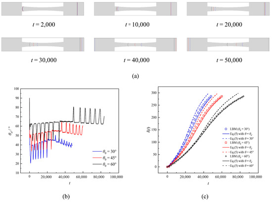
Figure 6.
(a) Liquid–liquid spontaneous imbibition process at different time steps for different wettability in the parabolic capillary. (b) Time evolution of contact angle during liquid–liquid spontaneous imbibition for different wettability. (c) Theoretical imbibition length with and without considering the dynamic contact angle with LBM results for different wettability.
3.3. Effect of Viscosity Ratio
For the conical capillary with a monotonically dispersive axial width, the real-time evolution of the DCA θd during imbibition at different viscosity ratios M is given in Figure 7a–c. For M = 0.2, the value of θd gradually increases over time, except for a local jump. The increased imbibition length results in a larger proportion of low-viscosity wetting fluid occupying capillary space, decreasing viscous drag. Although the capillary width gradually widens and reduces capillary force, the reduction in viscous drag is more significant, resulting in an acceleration of imbibition velocity and, ultimately, an elevation of DCA. In contrast, for M = 1.0, we can observe that the θd shows a decreasing trend with increasing imbibition time. This is because the two fluids have equal viscosity, and the imbibition velocity decreases gradually with the increase in the capillary width, leading to a gradual decrease in the value of the θd. Similarly, for M = 5.0, the viscosity of the wetting fluid is significantly larger than that of the non-wetting fluid. As the imbibition time increases, more and more large viscous fluid enters the capillary leading to an increase in viscous drag. Meanwhile, the imbibition velocity decreases more, and the trend of reducing DCA becomes more evident due to the gradual decrease in the capillary width. In addition, the dynamic contact angle effect decreases as the viscosity ratio increases. In Figure 7d, we show the time evolution of the imbibition length for different viscosity ratios M. It can be clearly seen that the LW equation, without considering the DCA, predicts a significantly higher imbibition length than the LBM. In contrast, the LW equation calculated using the DCA is very close to the LBM results. Specifically, in Case A, the primary driver for the decreasing DCA is the geometric effect—the increasing capillary width reduces the flow resistance, allowing the meniscus to advance faster, which, for a given set of fluid properties, can lead to a lower DCA. In the viscosity ratio study, for a low viscosity ratio (M = 0.2, meaning the displacing fluid is much less viscous than the displaced fluid), the viscous effect dominates. The high viscous resistance from the displaced fluid significantly slows the meniscus velocity. According to the hydrodynamic models, a slower meniscus velocity under these conditions correlates with a DCA closer to the static contact angle (SCA), which manifests as an increase in DCA over time.
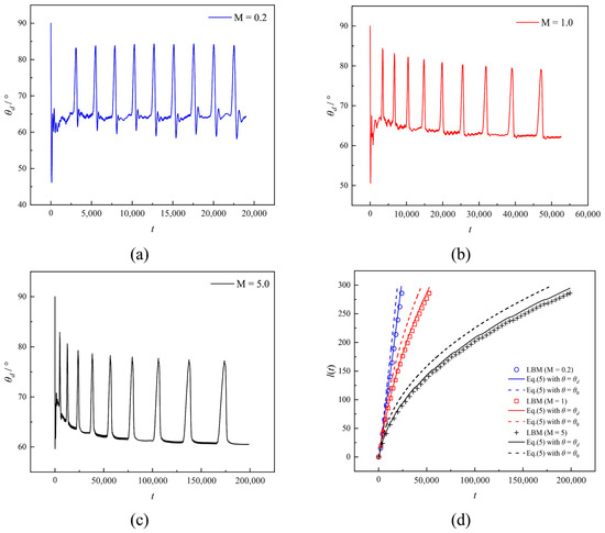
Figure 7.
(a) Time evolution of dynamic contact angle for M = 0.2 in the monotonically divergent conical capillary. (b) Time evolution of dynamic contact angle for M = 1.0 in the monotonically divergent conical capillary. (c) Time evolution of dynamic contact angle for M = 5.0 in the monotonically divergent conical capillary. (d) Theoretical imbibition length with and without considering the dynamic contact angle with LBM results for different viscosity ratios.10,000.
In Figure 8a–c, we show the time evolution of the DCA θd during imbibition in a monotonically convergent conical capillary with monotonically converging axial widths for different viscosity ratios M. It is evident that, except for local downward jumps, θd exhibits an overall increasing trend for M = 0.2 and M = 1.0. In contrast, it shows a decreasing trend for M = 5.0. The phenomenon can be attributed to the gradual convergence of capillary width, which increases capillary force. Meanwhile, for M = 0.2, the viscous resistance gradually decreases due to a large amount of wetting fluid being drawn into the capillary, leading to a gradual increase in DCA. For M = 1.0, the viscosity of both fluids remains constant, while the viscous resistance undergoes minimal changes. Capillary forces primarily govern the imbibition rate. As the axial width decreases, the capillary pressure increases and the value of θd. increases. On the contrary, as M increases to 5.0, a significant increase in viscous resistance is observed due to the influx of highly viscous fluid into the capillary during imbibition. Although there is an increase in capillary force, it is not as substantial as the increase in viscous force, resulting in a decrease in meniscus speed and the DCA that deviates from the expected SCA. The time evolution of the imbibition length for different viscosity ratios is shown in Figure 8d. It can be clearly seen that for M = 0.2 and M = 1.0, the imbibition length shows a super-linear relationship with time, which confirms that the imbibition rate increases gradually with the increase in imbibition time. For M = 5.0, the imbibition length shows an approximately linear relationship with time, indicating that the viscosity ratio has an essential effect on the imbibition rate. In addition, the LW equation corrected for dynamic contact angle generally agrees with the LBM results. In contrast, the LW equation cannot accurately predict the imbibition length without considering the DCA.
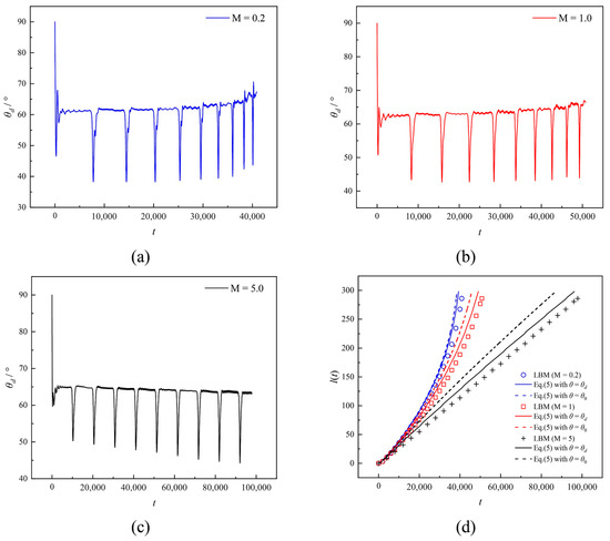
Figure 8.
(a) Time evolution of dynamic contact angle for M = 0.2 in the monotonically divergent conical capillary. (b) Time evolution of dynamic contact angle for M = 1.0 in the monotonically divergent conical capillary. (c) Time evolution of dynamic contact angle for M = 5.0 in the monotonically divergent conical capillary. (d) Theoretical imbibition length with and without considering the dynamic contact angle with LBM results for different viscosity ratios.
Figure 9a–c shows the time evolution of the DCA θd for different viscosity ratios M in the parabolic capillary. When M = 0.2, it can be seen that in the first half of the capillary, with the increase in imbibition time, the capillary width gradually decreases, and the viscous resistance also gradually decreases. Hence, the imbibition speed gradually increases, leading to the θd increases. And when the meniscus reaches the second half of the capillary, the capillary force gradually decreases due to the gradual increase in the capillary width. Still, the θd increases less due to a large amount of low-viscosity wetting fluid entering the capillary, leading to a smaller viscous drag. And when M = 1.0, the viscosity of both fluids is the same, and the imbibition rate depends on the change in capillary force. In the first half of the capillary, as the imbibition time increases, the capillary width gradually decreases, leading to an increase in the capillary pressure and, therefore, an increase in the imbibition rate leading to an increase in the value of the θd. In the second half of the capillary, the capillary width gradually increases, resulting in a decrease in capillary force and a corresponding decrease in imbibition velocity, resulting in a gradual reduction in the θd. On the contrary, for M = 5.0, θd can be increased briefly in the first half of the capillary, decreasing until the end of imbibition. This is because the viscous force of the wetting fluid dominates the imbibition process. Figure 9d shows the temporal evolution of imbibition length. It can be seen that the LW equation corrected for the DCA generally agrees with the LBM results, while the LW equation, without considering the DCA, cannot give an imbibition length consistent with LBM.
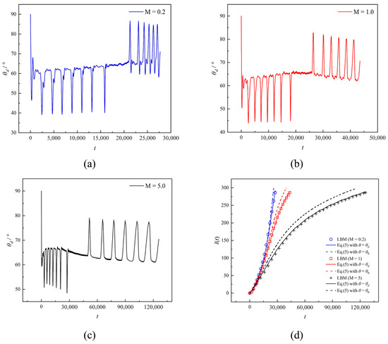
Figure 9.
(a) Time evolution of dynamic contact angle for M = 0.2 in the parabolic capillary. (b) Time evolution of dynamic contact angle for M = 1.0 in the parabolic capillary. (c) Time evolution of dynamic contact angle for M = 5.0 in the parabolic capillary. (d) Theoretical imbibition length with and without considering the dynamic contact angle with LBM results for different viscosity ratios.
4. Conclusions
In this paper, we proposed an extended LW equation that considers the contributions of the axial capillary shape, inertial forces, and viscous forces of the nonwetting fluid. Subsequently, we developed a cascaded Shan–Chen lattice Boltzmann model. In particular, we employed a contact angle scheme with an improved virtual density scheme, which effectively suppresses the unphysical density layer near the wall. Based on the theoretical model and the LBM, we simulated the liquid–liquid spontaneous imbibition process in three types of capillaries, including monotonically converging and diverging conical capillaries and parabolic capillaries. We also captured the real-time dynamic contact angle (DCA) of the meniscus. In addition, we analyzed the effect of wettability and viscosity ratio on the imbibition process within different capillaries and concluded the following:
- (1)
- The axial capillary geometry has an essential effect on the imbibition rate and the DCA for two-component fluids with equal viscosity. The DCA exhibits a gradual decrease in width with increasing capillary width and a gradual increase in width with decreasing capillary width. More importantly, the presence of the DCA will cause the LW equation to fail, and when we use the DCA data to correct the LW equation, the imbibition length predicted by the corrected LW equation is consistent with the LBM
- (2)
- Wettability exerts a specific influence on the dynamic contact angle (DCA) during imbibition. As wettability increases (indicated by a smaller static contact angle), capillary forces intensify, resulting in faster meniscus movement and an increased disparity between DCA and SCA. Similarly, for the capillary with different wettability, the imbibition length calculated using the LW equation corrected for the DCA almost agrees with LBM.
- (3)
- The viscosity ratio has a significant effect on the imbibition process. For a fixed viscosity of the non-wetting fluid, the viscosity of the wetting fluid is significantly smaller than that of the non-wetting fluid. The imbibition velocity increases in the middle and late stages of imbibition due to the smaller viscosity of fluid occupying more capillary space, leading to a rise in the DCA. On the contrary, the viscosity of the wetting fluid is significantly larger than the viscosity of the non-wetting fluid. As the imbibition time increases, the viscous resistance of the wetting fluid dominates the imbibition process and leads to smaller imbibition velocity and DCA. The imbibition lengths calculated using the LW equation with corrected dynamic contact angles are almost identical to LBM for wetting fluids with different viscosities.
This study is limited to two-dimensional, area-matched capillaries without gravity; density and viscosity ratios lie within moderate ranges; and θd is obtained from a model-based measurement. Future work will address fully three-dimensional pore networks, heterogeneous wettability patterns, gravity/buoyancy effects, and broader contrasts in fluid properties, and will include experimental validation of time-resolved θd in axially varying geometries.
Author Contributions
Conceptualization, F.P.; methodology, F.P. and S.Z.; investigation, F.P. and S.Z.; writing—original draft preparation, F.P. and S.Z.; writing—review and editing, K.W. All authors have read and agreed to the published version of the manuscript.
Funding
This work was supported by the National Natural Science Foundation of China (Grant NO. 52174041, 52104051, 52204058, and 51874319), the National Key Research and Development Project of China (Grant No. 2023YFA1011703), and the Beijing Natural Science Foundation (Grant No. 2232073).
Data Availability Statement
The original contributions presented in this study are included in the article. Further inquiries such as codes about the simulations can be directed to the corresponding author.
Conflicts of Interest
The authors declare no conflicts of interest.
References
- Morrow, N.R.; Mason, G. Recovery of oil by spontaneous imbibition. Curr. Opin. Colloid Interface Sci. 2001, 6, 321–337. [Google Scholar] [CrossRef]
- Mason, G.; Morrow, N.R. Developments in spontaneous imbibition and possibilities for future work. J. Pet. Sci. Eng. 2013, 110, 268–293. [Google Scholar] [CrossRef]
- Tian, W.; Wu, K.; Gao, Y.; Chen, Z.; Gao, Y.; Li, J. A critical review of enhanced oil recovery by imbibition: Theory and practice. Energy Fuels 2021, 35, 5643–5670. [Google Scholar] [CrossRef]
- Peng, X.; Wang, X.; Zhou, X.; Lin, Z.; Zeng, F.; Huang, X. Lab-on-a-chip systems in imbibition processes: A review and applications/issues for studying tight formations. Fuel 2021, 306, 121603. [Google Scholar] [CrossRef]
- Cai, J.; Chen, Y.; Liu, Y.; Li, S.; Sun, C. Capillary imbibition and flow of wetting liquid in irregular capillaries: A 100-year review. Adv. Colloid Interface Sci. 2022, 304, 102654. [Google Scholar] [CrossRef]
- Lucas, R. Rate of capillary ascension of liquids. Kolloid Z. 1918, 23, 15–22. [Google Scholar] [CrossRef]
- Washburn, E.W. The dynamics of capillary flow. Phys. Rev. 1921, 17, 273–283. [Google Scholar] [CrossRef]
- Siebold, A.; Nardin, M.; Schultz, J.; Walliser, A.; Oppliger, M. Effect of dynamic contact angle on capillary rise phenomena. Colloids Surf. A 2000, 161, 81–87. [Google Scholar] [CrossRef]
- Zhmud, B.V.; Tiberg, F.; Hallstensson, K. Dynamics of capillary rise. J. Colloid Interface Sci. 2000, 228, 263–269. [Google Scholar] [CrossRef] [PubMed]
- Fries, N.; Dreyer, M. The transition from inertial to viscous flow in capillary rise. J. Colloid Interface Sci. 2008, 327, 125–128. [Google Scholar] [CrossRef] [PubMed]
- Tian, W.; Wu, K.; Chen, Z.; Lai, L.; Gao, Y.; Li, J. Effect of Dynamic Contact Angle on Spontaneous Capillary-Liquid-Liquid Imbibition by Molecular Kinetic Theory. SPE J. 2021, 26, 2324–2339. [Google Scholar] [CrossRef]
- Erickson, D.; Li, D.; Park, C. Numerical simulations of capillary-driven flows in nonuniform cross-sectional capillaries. J. Colloid Interface Sci. 2002, 250, 422–430. [Google Scholar] [CrossRef] [PubMed]
- Young, W.-B. Analysis of capillary flows in non-uniform cross-sectional capillaries. Colloids Surf. A 2004, 234, 123–128. [Google Scholar] [CrossRef]
- Liou, W.W.; Peng, Y.; Parker, P.E. Analytical modeling of capillary flow in tubes of nonuniform cross section. J. Colloid Interface Sci. 2009, 333, 389–399. [Google Scholar] [CrossRef]
- Cai, J.; Jin, T.; Kou, J.; Zou, S.; Xiao, J.; Meng, Q. Lucas–Washburn Equation-Based Modeling of Capillary-Driven Flow in Porous Systems. Langmuir 2021, 37, 1623–1636. [Google Scholar] [CrossRef]
- Hultmark, M.; Aristoff, J.M.; Stone, H.A. The influence of the gas phase on liquid imbibition in capillary tubes. J. Fluid Mech. 2011, 678, 600–606. [Google Scholar] [CrossRef]
- Mumley, T.E.; Radke, C.; Williams, M.C. Kinetics of liquid/liquid capillary rise: I. Experimental observations. J. Colloid Interface Sci. 1986, 109, 398–412. [Google Scholar] [CrossRef]
- Fermigier, M.; Jenffer, P. An experimental investigation of the dynamic contact angle in liquid-liquid systems. J. Colloid Interface Sci. 1991, 146, 226–241. [Google Scholar] [CrossRef]
- Lorenceau, É.; Dequidt, G.; Bird, J.C. Capillary Displacement of Viscous Liquids. Langmuir 2016, 32, 3186–3190. [Google Scholar] [CrossRef]
- André, J.; Okumura, K. Capillary Replacement in a Tube Prefilled with a Viscous Fluid. Langmuir 2020, 36, 10952–10959. [Google Scholar] [CrossRef]
- Reyssat, M.; Courbin, L.; Reyssat, E.; Stone, H.A. Imbibition in geometries with axial variations. J. Fluid Mech. 2008, 615, 335–344. [Google Scholar] [CrossRef]
- Wang, Q.; Graber, E.R.; Wallach, R. Synergistic effects of geometry, inertia, and dynamic contact angle on wetting and dewetting of capillaries of varying cross sections. J. Colloid Interface Sci. 2013, 396, 270–277. [Google Scholar] [CrossRef]
- Gorce, J.B.; Hewitt, I.J.; Vella, D. Capillary Imbibition into Converging Tubes: Beating Washburn’s Law and the Optimal Imbibition of Liquids. Langmuir 2016, 32, 1560–1567. [Google Scholar] [CrossRef]
- Lei, J.; Xu, Z.; Xin, F.; Lu, T.J. Dynamics of capillary flow in an undulated tube. Phys. Fluids 2021, 33, 052109. [Google Scholar] [CrossRef]
- Shobeiri, A.; Ponga, M. A visco-inertial formulation for capillarity in irregular channels and tubes. Phys. Fluids 2021, 33, 117116. [Google Scholar] [CrossRef]
- Budaraju, A.; Phirani, J.; Kondaraju, S.; Bahga, S.S. Capillary Displacement of Viscous Liquids in Geometries with Axial Variations. Langmuir 2016, 32, 10513–10521. [Google Scholar] [CrossRef]
- Salama, A. Investigation of the imbibition/drainage of two immiscible fluids in capillaries with arbitrary axisymmetric cross-sections: A generalized model. J. Fluid. Mech. 2022, 947, A34. [Google Scholar] [CrossRef]
- Aidun, C.K.; Clausen, J.R. Lattice-Boltzmann Method for Complex Flows. Annu. Rev. Fluid. Mech. 2010, 42, 439–472. [Google Scholar] [CrossRef]
- Gunstensen, A.K.; Rothman, D.H.; Zaleski, S.; Zanetti, G. Lattice Boltzmann model of immiscible fluids. Phys. Rev. A 1991, 43, 4320–4327. [Google Scholar] [CrossRef]
- Cheng, Z.; Gao, H.; Ning, Z.; Wang, C.; Li, T. Inertial effect on oil/water countercurrent imbibition in porous media from a pore-scale perspective. SPE J. 2022, 27, 1619–1632. [Google Scholar] [CrossRef]
- Shan, X.; Chen, H. Lattice Boltzmann model for simulating flows with multiple phases and components. Phys. Rev. E 1993, 47, 1815–1819. [Google Scholar] [CrossRef] [PubMed]
- Swift, M.R.; Osborn, W.R.; Yeomans, J.M. Lattice Boltzmann simulation of nonideal fluids. Phys. Rev. Lett. 1995, 75, 830–833. [Google Scholar] [CrossRef]
- Boek, E.S.; Zacharoudiou, I.; Gray, F.; Shah, S.M.; Crawshaw, J.P.; Yang, J. Multiphase-flow and reactive-transport validation studies at the pore scale by use of lattice Boltzmann computer simulations. SPE J. 2017, 22, 940–949. [Google Scholar] [CrossRef]
- He, X.; Chen, S.; Zhang, R. A lattice Boltzmann scheme for incompressible multiphase flow and its application in simulation of Rayleigh–Taylor instability. J. Comput. Phys. 1999, 152, 642–663. [Google Scholar] [CrossRef]
- Attar, E.; Körner, C. Lattice Boltzmann method for dynamic wetting problems. J. Colloid Interface Sci. 2009, 335, 84–93. [Google Scholar] [CrossRef]
- Chen, L.; Kang, Q.; Mu, Y.; He, Y.-L.; Tao, W.-Q. A critical review of the pseudopotential multiphase lattice Boltzmann model: Methods and applications. Int. J. Heat Mass. Transf. 2014, 76, 210–236. [Google Scholar] [CrossRef]
- Chibbaro, S.; Biferale, L.; Diotallevi, F.; Succi, S. Capillary filling for multicomponent fluid using the pseudo-potential Lattice Boltzmann method. Eur. Phys. J. Spec. Top. 2009, 171, 223–228. [Google Scholar] [CrossRef]
- Zhang, S.; Li, J.; Chen, Z.; Wu, K.; Zhu, Q. Investigation on spontaneous liquid–liquid imbibition in capillaries with varying axial geometries using lattice Boltzmann method. Phys. Fluids 2023, 35, 122108. [Google Scholar] [CrossRef]
- Fei, L.; Qin, F.; Zhao, J.; Derome, D.; Carmeliet, J. Lattice Boltzmann modelling of isothermal two-component evaporation in porous media. J. Fluid Mech. 2023, 955, A18. [Google Scholar] [CrossRef]
- Zhang, S.; Li, J.; Zhu, Q.; Wu, K.; Chen, Z.; Wang, Z. Simulation of droplet dynamics in an inclined channel considering contact angle hysteresis using the cascade lattice Boltzmann method. Phys. Fluids 2024, 36, 012130. [Google Scholar] [CrossRef]
- Porter, M.L.; Coon, E.T.; Kang, Q.; Moulton, J.D.; Carey, J.W. Multicomponent interparticle-potential lattice Boltzmann model for fluids with large viscosity ratios. Phys. Rev. E 2012, 86, 036701. [Google Scholar] [CrossRef] [PubMed]
- Coelho, R.C.; Moura, C.B.; Telo da Gama, M.M.; Araújo, N.A.M. Wetting boundary conditions for multicomponent pseudopotential lattice Boltzmann. Int. J. Numer. Methods Fluids 2021, 93, 2570–2580. [Google Scholar] [CrossRef]
- Li, Q.; Yu, Y.; Luo, K.H. Implementation of contact angles in pseudopotential lattice Boltzmann simulations with curved boundaries. Phys. Rev. E 2019, 100, 053313. [Google Scholar] [CrossRef]
- Chassagne, R.; Dörfler, F.; Guyenot, M.; Harting, J. Modeling of capillary-driven flows in axisymmetric geometries. Comput. Fluids 2019, 178, 132–140. [Google Scholar] [CrossRef]
- Liu, H.; Sun, S.; Wu, R.; Wei, B.; Hou, J. Pore-scale modeling of spontaneous imbibition in porous media using the lattice Boltzmann method. Water Resour. Res. 2021, 57, e2020WR029219. [Google Scholar] [CrossRef]


Disclaimer/Publisher’s Note: The statements, opinions and data contained in all publications are solely those of the individual author(s) and contributor(s) and not of MDPI and/or the editor(s). MDPI and/or the editor(s) disclaim responsibility for any injury to people or property resulting from any ideas, methods, instructions or products referred to in the content. |
© 2025 by the authors. Licensee MDPI, Basel, Switzerland. This article is an open access article distributed under the terms and conditions of the Creative Commons Attribution (CC BY) license (https://creativecommons.org/licenses/by/4.0/).