Abstract
This paper presents a new method for detecting phase loss in Ynd transformers by integrating a Backup Interface Unit (BUI). Traditional detection techniques often struggle to reliably distinguish between genuine phase loss events and current imbalances caused by load variations, harmonics, or asymmetrical operating conditions, which can lead to delayed response or false triggering. The proposed method combines Clarke and Park transformations with controlled off-grid transition tests to enhance fault identification and validation. By applying these techniques, the system achieves higher sensitivity to true phase loss while maintaining robustness against normal operating disturbances. Simulation and laboratory experimental results confirm improved detection accuracy, reduced false positives, and faster protection response compared to conventional approaches. In addition, the method ensures continued operation and voltage stability during faults, which is critical for maintaining power quality and equipment safety. These advantages make the approach highly suitable for modern industrial facilities and smart grid applications where reliability and resilience are key requirements.
1. Introduction
In modern low-voltage power systems, Ynd transformers are commonly used for their ability to interface between different grounding schemes and isolate disturbances. However, when the load is connected on the primary side, as in certain backup systems or industrial installations, a loss of one of the supply phases can go undetected using conventional methods. This undetected phase loss can lead to equipment malfunction, unbalanced currents, or severe damage, especially in unmonitored systems.
This paper addresses the specific problem of detecting primary-side phase loss in Ynd transformer configurations, where the Primary (star) side is grounded, making traditional detection based on voltage asymmetry or unbalanced load ineffective. The challenge is further amplified when the system is powered through a backup source, such as a Battery Inverter Unit (BUI), where the usual current and voltage monitoring points may not reflect the true status of the upstream grid phases.
To solve this problem, a novel detection method is proposed that leverages measured primary-side currents and the use of Clarke transformation, allowing the identification of phase loss conditions even in cases where the current remains balanced or near-balanced. The detection method is implemented and tested through a Backup Interface (BUI) system, which provides both the measurement access and the computational framework to support real-time analysis and protection logic.
This research aims to develop a reliable, fast, and accurate method to detect phase loss in such configurations, thereby improving protection and continuity of supply for sensitive or critical systems. Experimental validation is conducted using a laboratory BUI-connected setup simulating phase loss conditions on the grid side, with results analyzed and compared against the expected transformer behavior.
1.1. Research Contribution and Scope
This work introduces a novel, dual-layer approach for detecting and validating phase loss events in Ynd transformers integrated with Backup Interface Units (BUIs). The proposed method combines Clarke and Park transformations with a secondary verification mechanism based on off-grid transition and voltage resampling. Unlike traditional detection methods that rely solely on current imbalance and are often prone to false positives, this framework ensures accurate fault classification and uninterrupted load support.
Through analytical modeling, LTspice simulations, and experimental testing using a full-scale BUI system, the method achieved a 96% detection accuracy with 0% false detections in test scenarios. It was successfully applied in edge conditions, including single-phase load imbalance, harmonic distortion (3rd, 5th, and 7th order), and MSC mode, where no active power is supplied from the grid. The methodology proved robust under various operational conditions, and the seamless switching ensured power continuity with transition times below 10 ms.
These findings not only address the limitations of conventional phase loss detection but also establish a practical foundation for real-time protective solutions in industrial and renewable energy systems. This work lays the groundwork for future extensions, including adaptive thresholds, detection of two-phase losses, and integration into microgrid protection architectures.
1.2. Phase Loss
Phase loss, commonly referred to as single phasing, poses significant challenges to electrical power systems, particularly in three-phase setups. This condition arises when one of the three phases in a three-phase system fails or becomes unavailable. The failure can be attributed to various causes, including fuse failures, circuit breaker trips, or physical damage to the transmission infrastructure, leading to numerous detrimental effects on connected equipment [1].
This issue is particularly challenging in medium voltage distribution networks, often found in rural or remote areas, where such faults are more likely to occur due to less robust infrastructure. An illustrative case occurred at Exelon Corporation’s Byron Generating Station, where the failure of an underhung insulator led to a disconnection and grounding incident, causing a significant unit trip and loss of offsite power [2,3,4].
Advanced methods include using microprocessor-based relays, which offer higher sensitivity and faster response times, thereby improving reliability in critical power supply systems [5,6].
The impact of phase loss primarily affects the operational integrity of power systems. Unbalanced loads resulting from phase loss can cause excessive heating and premature aging of electrical components. In induction motors, for example, single phasing can lead to significant efficiency losses and potential mechanical damage if not promptly mitigated [1]. Additionally, the economic implications include increased maintenance costs and potential downtimes, which are critical in industrial settings.
Previous research in the field of phase loss detection has primarily focused on current imbalance methods, which often fail to differentiate between genuine phase loss and disturbances such as harmonics or load transients, particularly in systems using Ynd transformers integrated with backup interfaces. This paper introduces a novel detection framework that combines Clarke and Park transformations with a verification stage via off-grid transition and current resampling. Unlike earlier methods, the proposed approach demonstrates high accuracy and robustness under complex operational conditions, including voltage sags, harmonic distortions, and maximum self-consumption (MSC) scenarios. The method was validated through simulations and real-world testing, confirming its ability to ensure seamless load operation during phase loss, eliminate false positives, and provide economic and safety benefits in industrial applications. Furthermore, the framework offers a scalable basis for future extensions, including two-phase loss detection, harmonic filtering, and smart-grid integration.
1.3. Phase Loss in Ynd Transformers Primary Side
The detection and protection against phase loss in Ynd (wye-delta) transformers are particularly challenging due to the unique configuration of their core and windings. In Ynd transformers, this issue is exacerbated by the fact that symptoms of phase loss may not clearly manifest on the secondary side, making traditional detection methods inadequate [4].
The reason is the specific core and winding configurations of these transformers. When an open phase occurs on the primary side, the inherent characteristics of a three-legged core type transformer allow the remaining phases to maintain stable voltage levels across the system [4]. This stability results from the magnetic paths within the core construction, which, despite the loss of one phase, still facilitate the flux movements necessary to sustain near-normal operating conditions. Therefore, the usual imbalance or significant voltage fluctuations expected with a phase loss may not manifest, making conventional detection methods based on voltage imbalances less effective. Also, Traditional protection methods sometimes fail to detect such conditions because they typically rely on measurements from the low side, where the effects of an open phase on the high side may not be apparent [7].
This subtle manifestation of phase loss underscores the need for specialized detection techniques capable of identifying such conditions without relying solely on the apparent electrical parameters typically monitored.
In the context of backup interface (BUI) systems, where the primary side of the transformer is directly connected to the load, detecting phase loss on the primary side is critical. The complexity arises because the delta side of the transformer, which serves the battery inverter, requires a delta connection without a neutral. This configuration is essential for the proper operation of the battery inverter, avoiding issues related to grounding and potential differences, and ensuring stable and reliable operation [8].
The primary challenge in detecting an open phase in Ynd transformers lies in the transformer operating under phase loss conditions for extended periods without triggering protection systems, especially under low loading conditions. This can result in the system continuing to operate with seemingly normal conditions, potentially leading to severe damage or failure if the phase loss condition persists undetected [2].
Advanced detection methods, such as those suggested in this document, can significantly improve reliability in critical power supply systems, such as the BUI system. These methods can detect subtle imbalances and phase loss conditions more effectively, thereby protecting the primary side load connected to the BUI system. Additionally, the practical solution of using a backup interface system can mitigate the risks associated with phase loss by seamlessly transitioning the load to an off-grid battery backup when an open phase is detected, maintaining operational integrity, and preventing damage [1].
Norouzi (2013) [4] also highlights the implications of open phase conditions in distributed generation (DG) contexts, where phase loss might go undetected due to specific core or winding configurations of the transformers used at these sites. This issue is critical, as many DG sites are in areas with a higher likelihood of phase loss on the utility side, and protections are often only on the low side of the transformer.
In summary, protecting against phase loss in Ynd transformers, particularly in BUI systems, requires a detailed understanding of transformer design, placement, and operational challenges. Effective detection and protection strategies must consider the unique characteristics of Ynd transformers and the potential for subtle manifestations of phase loss, especially on the primary side where the load is directly connected.
1.4. Use of Clarke and Park Transformations in Phase Loss Detection
The Clarke and Park transformations are pivotal in the analysis of three-phase electrical systems, particularly under conditions of phase loss and other asymmetries. Originally developed to simplify the analysis of electrical machines and power systems under variable conditions, these transformations convert three-phase system variables into a two-dimensional orthogonal system. This simplification is especially useful in detecting and diagnosing faults such as phase loss in complex systems like Ynd transformers and backup interface (BUI) systems.
Under balanced operation, the Clarke transformation results in I0 = 0 and a circular trajectory in the αβ plane. In phase loss conditions, I0 increases the α-β pattern becomes elliptical. This behavior, confirmed analytically and through simulation, allows accurate detection and classification of electrical anomalies.
Clarke Transformation: The Clarke transformation, a crucial analytical tool in power engineering, translates three-phase electrical quantities into two orthogonal components (α, β), effectively reducing the three-dimensional system to two dimensions. This transformation is instrumental in simplifying the analysis of phase-related anomalies by clearly depicting the system’s instantaneous power properties under unbalanced conditions. This technique is extensively utilized in fault detection, where traditional methods may not adequately reveal the nuances of phase loss or imbalance [3,9].
Clarke transformation on 3-phase current.
Park Transformation: The Park transformation extends the capabilities of the Clarke transformation by rotating the coordinate system aligned with the vector space of the machine’s magnetic flux, thereby facilitating the direct analysis of dynamic behaviors in rotating machinery. The transformation converts the α-β coordinates into direct (d) and quadrature (q) components, which are particularly sensitive to changes in phase conditions and can dynamically represent asymmetries and faults in electrical machines and power systems [3,4].
Park transformation on 3-phase current.
These transformations are theoretical constructs and practical applications in modern electrical engineering, particularly in the design and implementation of protection schemes for electrical power systems. For instance, they allow for the enhanced detection of phase loss in systems with complex transformer configurations, such as Ynd transformers, where traditional detection methods might fail to detect early or subtle signs of phase loss. The Park vector, representing the “pure” three-phase component of the system, remains invariant under balanced conditions and shows deviations when phase loss occurs, thus serving as a reliable indicator of system health [3,4].
In addition, the analytical strength of Clarke and Park transformations in handling nonsinusoidal and unbalanced conditions makes them invaluable in developing advanced diagnostic and protective technologies in electrical power systems. Their application in BUI systems, where reliability and uninterrupted operation are critical, underscores their significance in contemporary power system management [4].
By employing Clarke and Park transformations, researchers and engineers can develop more sensitive and accurate algorithms for detecting phase loss, which are crucial for maintaining the integrity and reliability of modern power systems. These transformations provide a robust framework for analyzing the current changes in the phases of a Ynd transformer primary side, enhancing the detection and protection mechanisms in place [3,7].
1.5. Backup Interface (BUI) Systems
Backup Interface Systems (BUI) play a pivotal role in modern power networks, particularly in hybrid microgrids that integrate renewable energy sources with traditional power generation systems. These systems are crucial in ensuring a reliable and uninterrupted power supply, especially in areas far from the utility grid or where grid stability is a concern. The seamless transition between grid-connected and standalone (off-grid) modes is a significant feature of BUI systems, enabling continuous power delivery despite grid inconsistencies or failures.
Seamless Transition Technology: BUI systems’ core functionality involves switching between on-grid and off-grid modes without interrupting the power supply to connected loads. This dual-mode operation is essential for areas that experience frequent power outages or critical loads requiring high reliability. The technology uses sophisticated control strategies to manage the transition phases, minimizing fluctuations in voltage and frequency, thereby protecting end-use equipment from potential damage caused by power quality issues [10].
Integration of Renewable Energy Sources: In BUI systems, renewable energy sources, such as photovoltaic panels and wind turbines, are often integrated with traditional diesel generators to form a resilient power supply framework. This integration is managed through advanced power electronic devices and intelligent control algorithms that ensure optimal power flow and maintain the balance between generation and load demand. Maximum Power Point Tracking (MPPT) algorithms enhance solar panels’ efficiency by adjusting the operating points to maximize power output under varying environmental conditions [10].
Energy Storage Systems: A critical component of BUI systems is the energy storage system (ESS), typically implemented with batteries. ESS plays a vital role in energy buffering and providing power during transitions or when renewable generation is insufficient. The BUI control systems manage these storage units’ charging and discharging processes to extend their lifespan and maintain system stability during abrupt power generation changes or load spikes.
Control and Management: The effective management of BUI systems relies on sophisticated control systems that can predict, react, and adapt to changes within the microgrid. This includes real-time monitoring of system parameters, predictive maintenance of equipment, and automated decision-making processes to switch between different power sources seamlessly. Advanced control techniques are increasingly being explored to enhance the autonomy and efficiency of BUI systems.
In summary, Backup Interface Systems equipped with seamless transition capabilities are fundamental to modern electrical networks, especially in hybrid microgrids. They ensure a reliable and continuous power supply by intelligently managing the interplay between various power sources and storage systems, thereby facilitating a stable transition between different operational modes. Integrating renewable energy sources within these systems further underscores their importance in developing a more sustainable and resilient energy infrastructure.
2. BUI System Overview
This section provides a comprehensive overview of the SolarEdge Backup Interface (BUI), a recently introduced solution designed to enhance reliability in markets afflicted by substandard grid quality, thereby minimizing frequent load disruptions. As illustrated in Figure 1, the BUI integrates four principal interfaces, each critical under varying operational conditions:
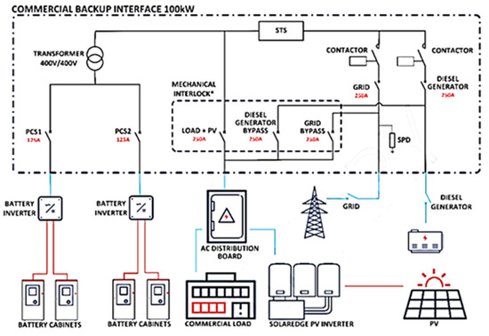
Figure 1.
SolarEdge BUI system overview diagram, red line(DC), blue line(AC) (SolarEdge user manual).
- Grid: The BUI can import energy from the grid or export energy to the grid, contingent upon the current operational mode.
- Diesel Generator (DG): Acts as a backup power source, supporting the load when no other power sources are available.
- Load + PV: This interface dynamically manages the power exchange; excess power from the photovoltaic (PV) system is fed into the BUI, whereas in situations where the load demand exceeds the PV output, the BUI supplies additional power to the load.
- Battery Inverter: This component is available in configurations with either one or two outputs. It allows the BUI to charge the batteries from any available power source or discharge them to support the load during power deficits.
A key objective of the BUI is to ensure continuous power delivery to the load by facilitating seamless transitions between these diverse power sources. Seamless transition requirements for backup systems ensure that electrical and electronic equipment can withstand voltage dips and short interruptions for up to 20 milliseconds, ensuring continuous operation without damage or malfunction due to brief power disruptions [11]. This requirement is crucial because many electronic devices can maintain operational continuity through internal energy reserves during such brief interruptions, thereby preserving functionality and data integrity. This is achieved using Silicon Controlled Rectifiers (SCRs) within Solid-State Transfer Switches (STS). SCRs are critical for their ability to switch rapidly, a necessity during power disturbances, allowing transitions in less than 100 microseconds, which depend on factors like anode current, di/dt, and temperature. Also, converter-grade SCRs have slower turn-off than inverter-grade types. SCRs are also favored in these applications for their ability to handle high voltages and currents [12]. This rapid switching capability is crucial when transitioning from grid power to the Energy Storage System (ESS) due to abrupt reductions in grid power, ensuring the reliability and consistency of power supply ([12]), defined as under 20 ms, which meets the minimum requirement for sensitive electronic devices to manage full voltage drops (interruptions) or substantial voltage decreases (dips) lasting up to 20 ms, as outlined in [11].
Moreover, the system architecture includes a transformer situated between the BUI and the battery inverters. This transformer is indispensable as it caters to the operational requirement for many battery inverters to maintain a floating neutral. In such setups, the transformer plays a critical role in ensuring that the neutral point remains stable and isolated, even when there are fluctuations or disturbances in the power system. This isolation helps prevent fault conditions and ensures that the electronic devices connected to the inverter operate reliably without interference from ground loops or potential differences that could lead to hazardous situations [8]. This fact introduces complexities in detecting a loss of phase. Given the challenges posed by potential phase loss, this aspect is pivotal in maintaining the system’s reliability and effectiveness.
In summary, the BUI is engineered to ensure operational continuity by adeptly managing power flows from various sources and securing rapid response to grid instabilities. Its design facilitates flexibility and reliability in power management and underscores its indispensable role in stabilizing grid operations in environments characterized by frequent power quality issues.
3. Methodology
This research adopts a comprehensive methodology to enhance phase loss detection in the primary side of wye grounded-delta (Ynd) transformers, which is crucial for maintaining system stability and reliability. The multifaceted approach integrates advanced signal processing techniques with practical system management through a Backup Interface System (BUI).
3.1. Current Change Analysis
The initial phase of the methodology focuses on detecting phase loss by analyzing changes in current distribution among the transformer phases. Traditional research shows that when a phase is lost, the currents in the remaining two healthy phases tend to increase, approximately doubling in magnitude. This increase has been widely used as a primary indicator of phase loss and is supported by existing research [2,7] (see Figure 2).
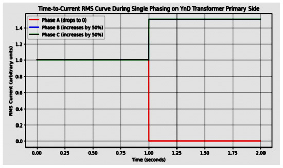
Figure 2.
Time-to-Current RMS Curve During Single Phasing on YnD Transformer Primary Side In systems without BUI.
This innovative approach helps mitigate the inaccuracies observed in traditional methods and enhances the reliability of phase loss detection by accounting for the influence of battery-supplied power. This refined methodology aims to provide more accurate and reliable detection of phase loss in Ynd transformers, ensuring greater system stability and operational efficiency.
As shown in Figure 2, traditional research methods focus on monitoring and analyzing current variations to identify and confirm the occurrence of a phase loss quickly. However, in the Backup Interface System (BUI) examined here, the currents in the healthy phases do not increase because the battery can compensate for the missing grid energy. The current in the lost phase will only drop to zero if an actual phase loss occurs.
In scenarios without phase loss, the system effectively operates with two transformers: the upstream transformer and the internal transformer. In this configuration, the phase angle influences the power flow between two buses, where the sending end voltage leads the receiving end voltage. Active power is directly proportional to this angle. In contrast, reactive power transfer depends on voltage magnitudes, flowing from the side with the higher voltage magnitude to the side with the lower voltage magnitude [13,14] (see Equations (3) and (4)). Consequently, current is expected to flow in the system under all conditions, even when no load is connected, except in cases of wire disconnection. This characteristic can be leveraged to identify phase loss situations [15].
Active and reactive power transfer between two sources.
Therefore, as explained, in the case investigated here with the BUI, the currents in the healthy phases may not increase similarly. However, we will still be able to identify the changes. One of the research goals is to simulate cases where this solution might cause false tripping. It is essential to consider and simulate scenarios that could trigger false trips, such as:
- Quick Changes in Loads: Sudden changes in load can cause transient imbalances that mimic phase loss.
- Malfunction of Equipment: Equipment like current transformers may malfunction, leading to inaccurate readings and false identifications.
- High Harmonic Levels: Non-linear loads can introduce harmonics, distorting current waveforms, potentially causing incorrect detection of phase loss.
- Load Imbalance: Uneven distribution of loads across phases can create conditions that falsely trigger phase loss protection.
- Transients: Temporary disturbances, such as switching operations or fault clearings, can affect current readings.
- Incorrect Settings: Improper configuration of protection systems can misinterpret normal variations as phase loss.
Another solution to prevent false identification involves the BUI, which plays a pivotal role in practical management. Upon detection of a phase loss, the BUI can seamlessly transition the load to an off-grid battery backup, thus isolating the transformer from the grid. This isolation is critical as it allows for a subsequent re-evaluation of the grid’s voltage without the influence of the transformer’s load. By re-checking the grid voltage in the absence of the transformer connection, the methodology can confirm whether a grid phase loss has occurred and identify the specific phase that has been lost, thereby validating the initial detection. This step is crucial for implementing corrective actions and further analyzing the grid’s stability and reliability.
3.2. Application of Clarke and Park Transformations
Clarke and Park transformations are employed to refine the detection process. These mathematical transformations convert three-phase current and voltage measurements into a two-dimensional coordinate system, facilitating easier analysis of power system dynamics. By applying these transformations, the research aims to enhance the precision of phase loss detection, making the identification process more efficient and reducing the likelihood of false positives. This technique allows for a detailed examination of the phase conditions, providing a clear, mathematical representation of the system’s electrical characteristics.
While direct measurement of the three-phase currents could be sufficient for basic phase loss detection, the use of Clarke and Park transformations offers several key advantages:
- a.
- Real-Time Monitoring
The use of Clarke and Park transformations is particularly advantageous for reducing detection time and enabling real-time monitoring and automation in power systems. By converting three-phase currents into simplified orthogonal components (Iα, Iβ) and a zero-sequence component (I0), the Clarke transformation streamlines the analysis, making detecting abnormalities faster than monitoring the raw currents directly. In a balanced system, the circular trajectory in the α−β plane and the zero value of I0 provide a clear baseline. Deviations from this baseline, such as distortions in the trajectory or an immediate rise in I0, instantly signal faults like phase loss or unbalanced loads. The Park transformation further enhances this capability by mapping the α−β components into a rotating reference frame, producing steady DC-like quantities (Id and Iq) that are ideal for fast fault detection. This reduces the processing burden, as the system only needs to monitor simple thresholds in Id and Iq rather than analyzing oscillatory waveforms, allowing for immediate fault identification. These transformations minimize detection latency and ensure precise, reliable results, making them invaluable for real-time system protection and fault classification.
- b.
- Improved detection sensitivity
The Clarke and Park transformations offer enhanced sensitivity by converting the three-phase current system into a two-dimensional coordinate system. This allows for more accurate detection of imbalances by isolating the zero-sequence component (I0) and identifying deviations in the transformed space. Unlike simple direct current measurements, which may miss minor deviations, this transformation highlights even subtle imbalances in the system. The ability to analyze the system’s dynamics in the α−β plane provides a more detailed representation of phase loss, enhancing detection sensitivity even under mild imbalance conditions.
- c.
- Enhanced Filtering of Harmonics and Noise
In practical systems, current measurements are often affected by harmonics, noise, and transient disturbances, which can lead to false detections or inaccurate diagnoses. By using the Clarke and Park transformations, harmonics and noise can be filtered out more effectively, focusing primarily on the fundamental frequency components. This noise reduction ensures a more accurate representation of the system’s condition, reducing the likelihood of false tripping due to high harmonic content. This capability is particularly important in systems with significant harmonic distortion, where directly measuring the current might lead to erroneous conclusions.
- d.
- Simultaneous Detection of Imbalances and Faults
Direct current measurement can reveal that a phase current has dropped to zero, but it does not provide detailed insight into the type of imbalance or fault that has occurred. The Clarke and Park transformations allow for simultaneous analysis of the symmetrical components: zero-sequence, positive-sequence, and negative-sequence currents. By distinguishing between these components, the method can help identify, with further development, not only phase loss but also other types of faults, such as unbalanced loads, open-phase conditions, or other disturbances. This distinction helps determine the imbalance’s nature more effectively than traditional current measurement.
- e.
- Compatibility with Control Systems
Another significant advantage of Clarke and Park transformations is their compatibility with modern control systems. Many advanced systems, such as inverter-based technologies, energy storage systems, and power quality management, rely on control algorithms that work in the d−q reference frame (provided by the Park transformation). By converting current and voltage measurements into the d−q components, the phase loss detection can seamlessly integrate with these control algorithms, improving system responsiveness and performance. This integration is particularly useful for real-time protection and control applications where fast and accurate fault detection is essential.
- f.
- Advanced Diagnostic Capabilities
The transformed components in the d−q reference frame (Park transformation) or the α−β plane (Clarke transformation) provide a clearer and more structured view of the system’s electrical characteristics. Specifically, the Id and Iq components in the Park transformation offer valuable diagnostic information about active and reactive power flow, making it easier to analyze phase loss and other fault conditions. This enhanced diagnostic capability supports real-time monitoring and the development of advanced protection schemes, improving the overall system’s reliability and resilience to faults.
To diagnose phase loss in a three-phase system using Clarke and Park transformations, we start by applying the Clarke transformation to the three-phase currents. The transformation mathematically decomposes the currents into a zero-sequence component (I0), indicating symmetry or imbalance among the phases, and two orthogonal components (Iα and Iβ) are analyzed for deviations from their expected patterns in a balanced system. Mathematically, the Clarke transformation is expressed as:
Clarke transformation on 3-phase current.
Clarke transformation enables precise differentiation between phase loss, load imbalance, and harmonic distortions by analyzing the transformed current components Iα, Iβ, and I0. In typical operation, Iα = In sin(ωt) and Iβ = In cos(ωt), forming a perfect circular trajectory in the α-β plane, while I0 remains zero, indicating a balanced system. However, in the case of phase loss (e.g., if Phase C is lost), the missing phase contribution disrupts symmetry, leading to a deviation from the circular trajectory. Mathematically, this results in:
Forming a distorted elliptical shape, while I0 becomes nonzero, with an amplitude of 1/3 of the phase amplitude, confirming the imbalance. A similar effect is observed with load unbalance, such as an 80% current reduction in one phase. In this case, the trajectory remains closer to circular, and I0 remains small, and defining the correct thresholds allows differentiation from complete phase loss.
Harmonic distortions behave differently. When 3rd harmonics are present, they appear only in the zero-sequence component:
While Iα and Iβ remain unaffected, distinguishing them from phase loss. In contrast, 5th and 7th harmonics distort Iα and Iβ, modifying the waveform but leaving I0 at zero, helping to differentiate them from phase imbalances. In a scenario with combined harmonics (3rd, 5th, and 7th), only the 3rd harmonic appears in I0, while the 5th and 7th harmonics distort Iα and Iβ, reinforcing the ability to distinguish harmonic interference from actual phase loss. This structured response enables the detection system to accurately classify faults and filter out transient disturbances, improving the reliability of phase loss detection.
Upon detecting the potential phase loss as described, the BUI will automatically switch to battery backup (off-grid mode). Concurrently, the grid input voltages are measured, and a modified Clarke transformation is applied to the voltages to analyze their dynamics independent of the transformer and load variations.
As previously assumed, Phase C is lost, and Phases A and B are intact. Initial phase voltages are Vc = 0.
Then, the Clarke transformation will be applied:
Clarke and Park transformation on 3-phase voltage during phase loss.
Clarke transformation allows confirming the identification of phase loss by analyzing the transformed voltage components Vα, Vβ, and V0. Under normal balanced operation, the three-phase voltages are symmetrically distributed, resulting in
Forming a circular trajectory in the α-β plane, while V0 remains zero, indicating a balanced system. However, when one phase voltage drops to zero (e.g., if Vc = 0), the symmetry is disrupted. The α-β trajectory is distorted as the missing phase contribution alters the voltage distribution, resulting in:
More importantly, the zero-sequence component V0, which was initially zero, becomes:
Reflecting the imbalance. This increase in V0 serves as a clear indicator of phase loss, distinguishing it from scenarios such as load imbalance or harmonic distortions, where V0 remains small or unchanged.
In the investigated case, it should be sufficient to verify phase-loss, because of its sensitivity to imbalances, the isolation of the zero-sequence component (V0), which can solely indicate the phase loss, and its computational simplicity.
Anyway, Park transformation can provide additional benefits in more complex or dynamic scenarios, particularly when you need to monitor not just phase loss but also other system behaviors or when real-time control is required.
The discrepancy or abnormal pattern confirms the phase loss by analyzing the post-transition grid voltages using PQ transformations. If grid phase loss is not confirmed by voltage, it ensures that no grid phase loss occurred because the measurement point is isolated from the transformer.
In this scenario, there are two main possibilities:
Phase Loss within the BUI: A phase loss may occur internally within the Backup Interface System.
False Identification: As detailed earlier, other causes might have triggered a false identification. For this option, scenarios that might trigger false detection will be simulated during the tests. These scenarios include:
- Quick changes in loads.
- Malfunction of equipment, such as current transformers.
- High harmonic levels.
- Load imbalance.
- Transients.
- Incorrect settings.
By simulating these conditions, the research aims to evaluate the robustness of the detection system and improve its accuracy in distinguishing between actual phase loss and false identifications. This testing will help refine the methodology and enhance the reliability of phase loss detection in Ynd transformers.
3.3. Reconnection and System Evaluation
Once the phase loss is confirmed and appropriate measures are taken to stabilize the system, the methodology includes criteria for safely reconnecting the transformer to the grid. This reconnection is contingent upon the restoration of normal phase conditions and grid stability, ensuring that the transformer and connected loads are protected from potential damage caused by an unstable power supply [16,17].
To conclude, the proposed methodology leverages both advanced analytical techniques and practical system management tools to address the critical issue of phase loss in delta-wye transformers, included in BUI systems. By integrating current change analysis, Clarke and Park transformations, and the dynamic capabilities of the BUI, this approach not only detects phase loss more effectively but also enhances the overall resilience and reliability of the power system [18,19].
3.4. Step-by-Step Phase Loss Identification Presentation
A typical Ynd transformer system with a Backup Interface Unit (BUI) was selected for the study. The BUI enables fast transition to off-grid mode and includes voltage and current measurement capabilities.
- 1.
- Current Measurement:
The detection logic is based on a single current measurement taken at the primary side of the transformer (before the star point). This simplifies implementation and reduces the need for multiple CTs.
- 2.
- Clarke Transformation:
The three-phase current signals are processed using Clarke transformation to obtain the α (Iα), β (Iβ), and zero-sequence (I0) components. This transformation maps the three-phase system into a two-dimensional orthogonal plane plus a zero-sequence scalar.
- 3.
- Behavioral Analysis:
Under normal, unbalanced, and faulty conditions (e.g., phase loss), the behavior of Iα, Iβ, and I0 differs. These differences were derived mathematically and validated via simulation.
- 4.
- Fault Detection Logic:A rule-based algorithm was developed to detect phase loss by identifying characteristic patterns in the Clarke components:
- a.
- Sudden amplitude drop in Iα and/or Iβ
- b.
- Rise or distortion in I0
- c.
- Phase shift between Iα and Iβ
- 5.
- Verification via Off-Grid Transition:
The system performs a rapid off-grid transition to eliminate false positives and re-measures current behavior. If abnormal conditions persist, the phase loss is confirmed.
- 6.
- Simulation and Validation:
The method was simulated using LTSpice and verified under various scenarios: normal operation, single-phase loss, load imbalance, and harmonic distortion (3rd, 5th, and 7th). Results were compared to theoretical predictions.
4. Results and Discussion
To simulate the system’s behavior and evaluate the proposed method, the system was modeled in LTspice. Figure 3 and its parameters in Table 1 illustrates the design of the system within the LTspice environment.
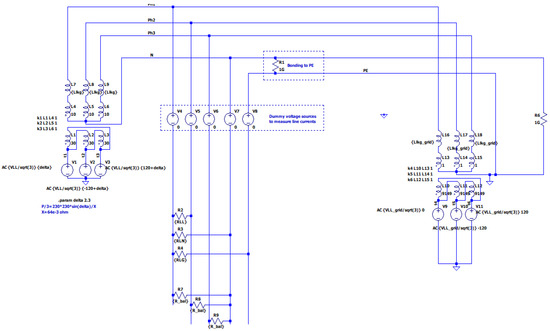
Figure 3.
LTspice simulation model, blue line’s (AC system).

Table 1.
LTspice simulation parameters.
To validate the proposed phase loss detection method, simulations were conducted under multiple operating conditions, analyzing the behavior of Iα, Iβ, and I0 in each case. The results confirm the ability of Clarke and Park transformations to distinguish between phase loss, load imbalances, and harmonic distortions.
In a balanced three-phase system with no faults, Iα and Iβ form a perfect circular trajectory in the α-β plane, and I0 remains zero, indicating a balanced system.
In A complete loss, when Phase C is disconnected, the result is that the trajectory of Iα and Iβ becomes distorted from a circle, and I0 increases significantly (1/3 phase amplitude), confirming the phase imbalance [20,21].
In a case where one phase voltage is reduced to 80% of its nominal value, while the other two remain unchanged. The result indicates that Iα and Iβ show minor trajectory distortion but remain approximately circular, and I0 increases slightly but does not reach phase loss levels, distinguishing it from full disconnection.
In a case where the system has balanced voltages but contains 3rd harmonic distortion, the result shows that Iα and Iβ remain unchanged. In contrast, I0 contains only the 3rd harmonic component, differentiating harmonic distortion from phase loss.
As in Figure 4, the simulation shows the values of Iα, Iβ (30 A), and I0 under ideal balanced conditions. As expected, I0 remains zero, while Iα and Iβ form a circular waveform indicative of a perfectly balanced system.
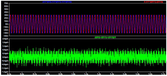
Figure 4.
I0 (green), Iα, and Iβ in a balanced load (red and blue).
Figure 5 demonstrates the impact of a complete loss of phase C after one second of the simulation. I0 rises significantly to 7 A due to the imbalance, and the Iα–Iβ trajectory shifts from circular to elliptical, indicating asymmetry and confirming phase loss.
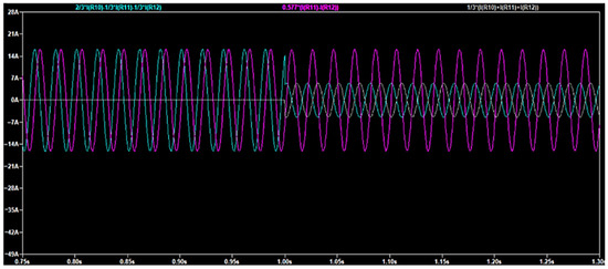
Figure 5.
I0 (grey), Iα and Iβ (light blue and purple) before and after the phase C loss.
Figure 6 shows the phase C loss after one second of the simulation, where the current decreased from 20A to zero.
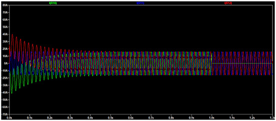
Figure 6.
Phases currents before and after phase C loss.
Figure 7—load imbalance (80% current reduction in phase C, decrease from 30 A to 24 A). Here, the load on phase C is reduced but not fully disconnected. I0 increases moderately, and the Iα–Iβ waveform becomes slightly distorted but does not resemble full phase loss, allowing the system to distinguish load unbalance from fault.
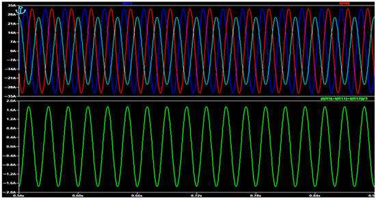
Figure 7.
Phases currents (up) and I0 (down) during current imbalance.
In Figure 8, all phases are injected with a 3rd harmonic component. As expected, I0 becomes non-zero due to the zero-sequence nature of the 3rd harmonic, but Iα and Iβ remain unchanged, preserving their circular pattern.
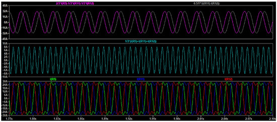
Figure 8.
Phases currents (down) and I0 (middle), Iα, and Iβ (up) in the presence of a 3rd harmonic load.
In Figure 9, the simulation presents the effect of a 5th harmonic component injected into all three phases. Unlike the 3rd harmonic, the 5th harmonic introduces unequal phase shifts, resulting in distortion in the Iα and Iβ components. The I0 component remains nearly zero, while the Iα–Iβ pattern becomes elliptical and warped, indicating harmonic distortion without indicating phase loss.
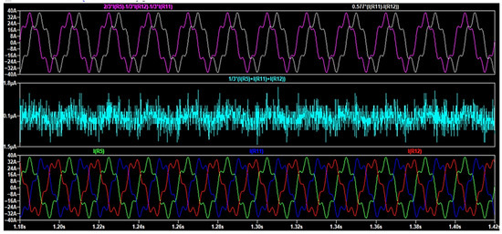
Figure 9.
Phases currents (down) and I0 (middle), Iα, and Iβ (up) in the presence of a 5th harmonic load.
4.1. Experimental Validation with Oscilloscope Data
In addition to the simulation, an experimental validation was conducted to verify the findings under real-world conditions. Using a high-resolution oscilloscope, the following key observations were recorded:
Transformer Primary Side Response: As depicted in Figure 10, the current in the lost phase (L3) dropped to near zero, while the currents in L1 and L2 exhibited minor fluctuations rather than the expected increase.
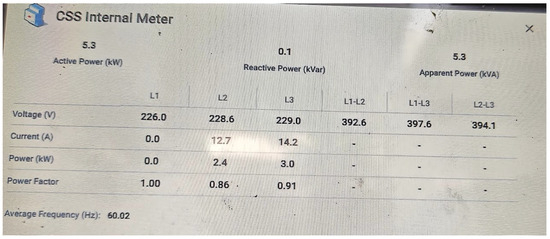
Figure 10.
Transformer primary side currents during single phasing.
Voltage Stability: The primary and secondary voltages remained stable despite the phase loss, as shown in Figure 11.
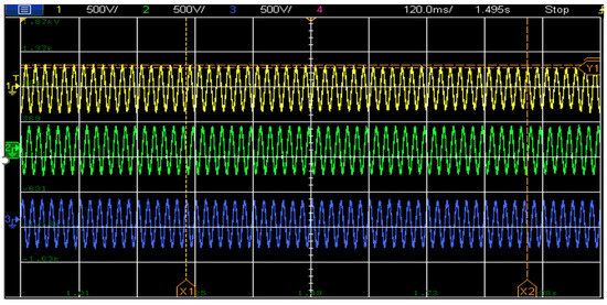
Figure 11.
3-phase voltages during single-phase trip (single phasing), Y1 (Yellow 268 V), Y2 (Green 308 V), Phase difference (40 V). It can be seen that the grid voltage stays stable even when the phase “falls” due to the internal transformer.
This further reinforces the expected behavior of a Ynd transformer, where the core design sustains voltage levels even under phase loss conditions.
False Tripping Scenarios and System Response: To evaluate the robustness of the detection method, several scenarios that could potentially cause false phase loss detection were simulated:
- Load imbalance: Introducing a zero-load condition in one phase while maintaining load in the other two phases.
- Harmonic distortions: Injecting harmonics at 5%, 10%, and 15% THD using third, fifth, and seventh-order harmonics.
- Sudden load changes: Simulating rapid load switching events.
- Transient disturbances: Introducing high-frequency transients.
In some cases, the system identified high imbalance conditions through Clarke and Park transformations and switched to off-grid mode (see Figure 12). The system then re-evaluated the grid voltage by disconnecting the BUI, confirming that all three phase voltages were intact, indicating no actual phase loss. Consequently, the system reconnected to the grid, ensuring a continuous power supply to the load (see Figure 13).
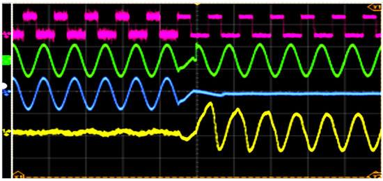
Figure 12.
On-grid to Off-grid transition. We see in this picture the transition from on-grid to off-grid, Green—Load Voltage (366 V)—we see a short interrupt when grid voltage falls, Blue—Grid Voltage (366 V to zero), Yellow—PCS/battery current (±97 A).
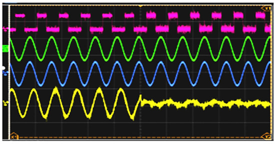
Figure 13.
This picture presents the transition from off-grid to on-grid Green—Load Voltage (366 V)—we see a seamless transition without interruption on the voltage, Blue—Grid Voltage (366 V), Yellow—PCS/battery current (±97 A to almost zero).
The transition between on-grid and off-grid modes was seamless, with voltage deviations lasting less than 10 ms, as seen in the green waveform of Figure 12. Switching back to grid operation also maintained uninterrupted power for the load. The blue waveform represents grid current, while the yellow waveform indicates PCS (Battery Inverter) current.
4.2. Key Findings from the Experimental Results:
- Voltage Stability: The transformer core design allows the voltages on both the primary and secondary sides to remain stable despite phase loss.
- Current Distribution in BUI Systems: Unlike traditional systems, the healthy phase currents do not increase significantly due to the compensating effect of the battery storage.
- Seamless Transition: The BUI successfully transitions to off-grid operation in less than 10 ms, ensuring a continuous power supply without noticeable interruptions.
- False Tripping Prevention: By implementing secondary voltage verification, the system effectively distinguishes between actual phase loss and temporary imbalances caused by harmonics, transients, or load changes.
These findings confirm that the proposed method offers enhanced accuracy in detecting phase loss while minimizing false tripping, making it a robust solution for BUI-integrated Ynd transformer systems.
Experimental tests using a BUI-integrated system showed 100% accurate detection of simulated phase loss, while avoiding false triggers under load imbalance or harmonics. LTspice simulations further demonstrated the ability of the method to differentiate 3rd, 5th, and 7th harmonics based on the behavior of I0, Iα, and Iβ.
While the method showed high reliability, some false trips occurred under fast load switching due to voltage fluctuations. Future work will focus on threshold optimization, extension to two-phase faults, and integration with smart grid systems for predictive diagnostics.
5. Conclusions
This research presents a scalable, accurate, and validated solution for phase loss detection in Ynd transformers. It ensures continuous load operation, minimizes false detections, and enhances protection in complex environments, including MSC and high-harmonic systems. The method sets a new standard for transformer protection and paves the way for smarter grid fault detection.
This research has introduced several innovative approaches to detecting and managing phase loss in wye-grounded delta (Ynd) transformers integrated with a Backup Interface System (BUI). The key findings and contributions of this study are outlined as follows:
- Continuous Operation During Grid Disconnection: A significant advancement presented in this work is the proposed system’s ability to maintain continuous load operation even when the grid circuit breaker is tripped. Unlike traditional systems, where grid disconnection often results in load interruptions, the BUI ensures that the load remains powered, highlighting a crucial improvement in system reliability.
- Prevention of False Tripping: The research introduces a novel method for preventing false tripping by implementing additional testing when the transformer is isolated from the grid. This approach addresses a gap identified in previous research, where certain scenarios could mimic phase loss, leading to unnecessary system tripping. The method enhances the accuracy of phase loss detection, thereby improving system stability.
- Simulation of False Tripping Scenarios: This study uniquely attempts to simulate false tripping under various conditions that do not involve actual phase loss. The goal is to investigate whether other factors might cause current changes, leading to incorrect phase loss detection. The findings indicate that while the system is robust, further exploration of potential false tripping scenarios is necessary to ensure comprehensive system resilience.
- System Performance Under Different Power Supply Conditions: The methodology demonstrates that the proposed system maintains effective performance even when the grid’s active power supply is zero, such as when batteries or photovoltaic (PV) systems power the load. This was particularly evident in scenarios like MSC mode, where no active power from the grid is supplied to the BUI. In this case, as simulated, reactive power exchanges between the upstream and internal transformers supported the load without requiring input from the grid. This capability highlights the system’s versatility and reliability across various operational conditions, ensuring continuous load support even in the absence of grid-supplied active power.
- Validation Procedure: The research suggests that after detecting an imbalance in currents, the validation procedure should be repeated multiple times to ensure the accuracy of the detection. Future studies should establish the optimal number of repetitions necessary to minimize false identifications while ensuring timely and reliable phase loss detection.
- Future Research Directions:
- Two-Phase Loss Identification: Future research should explore detecting and testing two-phase loss scenarios to expand the system’s detection capabilities.
- Locating the Phase Loss: Further investigation is needed to determine whether the phase loss occurs internally or externally to the system. Distinguishing the location of the phase loss is critical for implementing targeted corrective actions.
- Detection of Other Faults Using the BUI: The BUI system, as demonstrated in this research, provides new opportunities for fault detection beyond phase loss. Future studies could explore its potential to identify other types of faults, thereby enhancing overall system stability and protection.
- Optimization of Protection Thresholds: Each site exhibits unique characteristics in terms of typical load variations and inherent system imbalance. Further research is required to optimize the protection thresholds for each specific installation, ensuring that phase loss detection is both accurate and reliable. By fine-tuning these thresholds, unnecessary phase loss identifications and unintended transitions to off-grid mode can be minimized, enhancing system stability and operational efficiency.
In conclusion, this research significantly advances the field of phase loss detection in Ynd transformer systems by introducing a reliable BUI integration that prevents false tripping and ensures continuous operation under various conditions. These findings not only address current gaps in the literature but also pave the way for future innovations in fault detection and system optimization.
Author Contributions
Conceptualization, M.S. and C.B.; methodology, M.S. and C.B.; software, C.B. and A.V.; validation M.S., C.B. and A.V.; formal analysis, M.S., C.B., A.V., N.T. and Y.P.; writing—original draft preparation M.S., C.B.; writing—review and editing, C.B., A.V., Y.P. and N.T.; supervision, M.S. All authors have read and agreed to the published version of the manuscript.
Funding
This research received no external funding.
Data Availability Statement
The original contributions presented in this study are included in the article. Further inquiries can be directed to the corresponding author.
Conflicts of Interest
Authors Yuval Paz and Nikolay Tal were employed by the company SolarEdge. The remaining authors declare that the research was conducted in the absence of any commercial or financial relationships that could be construed as a potential conflict of interest.
Nomenclature
| Abbreviation | Interpretation |
| BUI | Backup Interface |
| ESS | Energy storage systems |
| SE | SolarEdge |
| STS | Static switch |
| SCR | Silicon-controlled rectifier |
| STS | Solid-State Transfer Switches |
| Ms | milli seconds |
| MsC | Maximal self-consumption |
| DG | Distributed generation |
| Ah | ampere-hour |
| Li-ion | Lithium-ion battery |
| PV | photovoltaic |
| Qm | maximal releasable capacity |
| SEMC | system energy management controller |
| SoC | State of Charge |
| SoH | State of Health |
| Wh | watt-hour |
References
- Kersting, W.H. Causes and Effects of Single-Phasing Induction Motors. IEEE Trans. Ind. Appl. 2005, 41, 1499–1503. [Google Scholar] [CrossRef]
- Johnson, G.; Hamilton, R.; Thakur, S. Effect of Transformer Connection and Construction on Single Phasing Detection. In Proceedings of the 2013 66th Annual Conference for Protective Relay Engineers, Spokane, WA, USA, 30 January 2012. [Google Scholar]
- Ferrero, A.; Superti-Furga, G. A New Approach to the Definition of Power Components in Three-phase Systems Under Nonsinusoidal Conditions. IEEE Trans. Instrum. Meas. 1991, 40, 568–573. [Google Scholar] [CrossRef]
- Norouzi, M. Open Phase Conditions in Transformers: Analysis and Protection Algorithm. In Proceedings of the 2013 66th Annual Conference for Protective Relay Engineers, Pullman, WA, USA, 8–11 April 2013. [Google Scholar]
- Refaat, S.S.; Abu-Rub, H.; Saad, M.S.; Aboul-Zahab, E.M.; Iqbal, A. Detection and Discrimination between Unbalanced Supply and Phase Loss in PMSM Using ANN-based Protection Scheme. In Proceedings of the 7th IEEE GCC Conference and Exhibition (GCC), Doha, Qatar, 17–20 November 2013; pp. 430–435. [Google Scholar]
- Blackburn, J.L.; Domin, T.J. Protective Relaying Principles and Applications, 4th ed.; CRC Press: New York, NY, USA, 2014. [Google Scholar]
- Basler Electric. A Practical Guide for Detecting Single Phasing on a Three-Phase Power System. In Proceedings of the Western Protective Relay Conference, Spokane, WA, USA, 15–17 October 2013. [Google Scholar]
- Mohan, N.; Undeland, T.M.; Robbins, W.P. Need for and Types of Electrical Isolation. In Power Electronics: Converters, Applications, and Design, 3rd ed.; John Wiley & Sons: Hoboken, NJ, USA, 2002; pp. 702–704. [Google Scholar]
- Retter, G.J. Matrix and Space-Phasor Theory of Electrical Machines; Akadémiai Kiadó: Budapest, Hungary, 1987. [Google Scholar]
- Elsherbiny, A.A.M.; Nada, A.S.; Ahmed, M.K. Smooth transition from grid to standalone solar diesel mode hybrid generation system with a battery. Int. J. Power Electron. Drive Syst. 2019, 10, 2065–2075. [Google Scholar]
- IEC 61000-4-11; Electromagnetic Compatibility (EMC)—Part 4-11: Testing and Measurement Techniques—Voltage Dips, Short Interruptions and Voltage Variations Immunity Tests for Equipment with Input Current up to 16 A Per Phase. 3rd ed. NSAI Standards. International Electrotechnical Commission: Dublin, Ireland, 2020.
- Faisal, M.; Hannan, M.A.; Ker, P.J.; Rahman, M.S.B.A.; Mollik, M.S.; Mansur, M.B. Review of Solid State Transfer Switch on Requirements, Standards, Topologies, Control, and Switching Mechanisms: Issues and Challenges. Electronics 2020, 9, 1396. [Google Scholar] [CrossRef]
- Kuperman, A.; Rabinovici, R. Shunt voltage regulators for autonomous induction generators. Part II: Circuits and systems. In Proceedings of the 2004 11th IEEE International Conference on Electronics, Circuits and Systems ICECS 2004, Tel-Aviv, Israel, 13–15 December 2004. [Google Scholar]
- Heydt, G.T. Electric Power Quality; Stars in a Circle Publications: Lafayette, IN, USA, 1991. [Google Scholar]
- Methods for Analyzing and Detecting an Open Phase Condition of a Power Circuit to a Nuclear Plant Station Service or Startup Transformer; Nuclear Regulatory Commission: Rockville, MD, USA,, 2014; pp. 1–24.
- Texas Instruments. Sensored Field Oriented Control of 3-Phase Induction Motors; Texas Instruments: Dallas, TX, USA, 2008. [Google Scholar]
- IEEE 1547-2018; Standard for Interconnection and Interoperability of Distributed Energy Resources with Associated Electric Power Systems Interfaces. IEEE Xplore: New York, NY, USA, 2018.
- Blackburn, W. Protective Relaying: Theory and Applications; Marcel Dekker Inc.: New York, NY, USA, 1998. [Google Scholar]
- Duffey, W.A.; Stratford, R.P. Understanding Symmetrical Components for Power System Modeling; Wiley-IEEE Press: Piscataway, NJ, USA, 2016. [Google Scholar]
- Rashid, M.; Mohan, N. Turn on and OFF Characteristics of SCR. Available online: https://www.scribd.com/presentation/556268924/Turn-ON-and-Off-characteristics-of-SCR (accessed on 3 October 2019).
- Bollen, M.H.J.; Etherden, N.; Yang, K.; Chang, G.W. Continuity of supply and voltage quality in the electricity network of the future. In Proceedings of the 2012 IEEE 15th International Conference on Harmonics and Quality of Power, Hong Kong, China, 17–20 June 2012. [Google Scholar]
Disclaimer/Publisher’s Note: The statements, opinions and data contained in all publications are solely those of the individual author(s) and contributor(s) and not of MDPI and/or the editor(s). MDPI and/or the editor(s) disclaim responsibility for any injury to people or property resulting from any ideas, methods, instructions or products referred to in the content. |
© 2025 by the authors. Licensee MDPI, Basel, Switzerland. This article is an open access article distributed under the terms and conditions of the Creative Commons Attribution (CC BY) license (https://creativecommons.org/licenses/by/4.0/).