Abstract
This work established a finite element analysis (FEA) model of an inserted tooth-type slip assembly under bear setting load and axial load, calculated the differences between the inserted teeth of the sidetracking packer slip-formed furrow shapes on the casing face, and analyzed the setting reliability of the inserted tooth slip sidetracking packer. The orthogonal optimization analysis of the structural parameters of the sidetracking packer was carried out on the basis of the furrow effect. Finally, the setting experiment was conducted with the inserted tooth slip sidetracking packer developed to verify correctness of the FEA model and the simulation results. The results show that in the FEA and calculation of the setting process of the inserted tooth-type slip, it is not only necessary to consider the furrow friction coefficient, but also the effect of the ridge on the furrow friction coefficient. The corresponding furrow friction coefficient varies according to the different furrow effects occurring on the casing surface caused by the various types of teeth inserted on the packer slips. The furrow effect is related to the sharpness of the tooth tips of the slips. The sharper the tooth tips, the more obvious the furrow effect is. Under the dual effects of the furrow effect and the adhesion effect, the carbide teeth of the slip feed into the casing wall to produce a uniform and distinct indentation on the premise of meeting the inserted tooth strength to ensure a reliable setting and hanging the inserted tooth slip sidetracking packer. The optimal combination of slip parameters was obtained by taking the optimal bite depth uniformity as the objective function: slip tooth installation spacing L = 10 mm, slip tooth installation angle α = 80°, slip tooth diameter d = 10 mm, and slip wedge angle β = 6°. The standard deviation of bite depth uniformity of the optimized slip teeth is 74.45% lower than that before optimization. The research results of this paper basically meet the requirements of engineering applications.
1. Introduction
Casing window sidetracking is one of the most important measures for exploiting the remaining oil and gas reservoirs at low cost during the middle and later periods of an oil field, especially whipstock sidetracking, at present. The whipstock consists of a guider and packer, and as one of the most important parts of the packer, if the slip is invalid or its supporting force is inadequate during sidetracking, it will cause slide-down of the sidetracking packer, which will lead to failure of the window cutting [1,2]. The geometrical shape, size, quantity, tooth distribution mode of the slip tooth and the structure, and material and machining accuracy of the slip will affect the occlusive force distribution between the slip and the casing [3]. The common slip system of a sidetracking packer consists of two parts at a distance of 1 m apart. The upper slips are mainly used to prevent rotation and the lower slips are mainly used to prevent sliding [4,5]. Compared with the tooth-milling slips, the inserted tooth slips are more convenient for processing [6], and the structure shortens the length of the setting tool, which is conducive to the safety of construction.
Wu [7] performed elastic–plastic contact FEA of the tooth-milling slips, and simulated the deformation and stress distribution of these types of slips under actual working conditions. Wang [8] performed FEA and structural improvement on the inserted tooth slips for a horizontal well-fracturing packer and studied the influence of the distance between slip teeth on the safety of the slip-setting process. Wu [9] calculated the stress and deformation state of the tooth-milling slips of packers under multiple coupling conditions by means of the FEA method, incremental load approach, augmented Lagrange multiplier method, and Newmark method. Wang [10] put forward a three-dimensional photoelastic simulation experiment to analyze the contact stress between the slip of the production packer and the casing and compared the result of the numerical calculation with that of the three-dimensional photoelastic experiment. Zhang Derong [6] designed a new pattern for an inserted tooth slip sidetracking packer and performed FEA of the reliability of the slip setting. Chen [11] studied the relationship between slip hanger bite depth and suspension load in the Φ 273 mm WE-type slip hanger in the Northwest Oilfield in China through experiment, theoretical computation, and finite element analysis. The study results show that the bite mark of the slip insert in the casing is deeper in the lower part of the sitting position, and the maximum bite depth of the slips in the casing gradually increases with the suspension load.
Although there are numerous analyses of and published studies on packer slips, the influence of the furrow [12,13] effect on the occlusive force distribution of slip teeth and casings, as well as the stability of the setting, has never been taken into consideration. Studies by Xie [14] indicated that as the load increases, the deformation in the contact area gradually changes from elastic to plastic, and the friction mechanism gradually changes from interface to furrow. This study has established a contact model for an inserted tooth slip and casing in FEA software ABAQUS and calculated the furrow effects in the process of tooth insertion and casing setting, as well as other furrow effects of different tooth types, and analyzed the setting reliability of the inserted tooth slip so as to provide a reliable basis for a feasibility study of the inserted tooth slip sidetracking packer.
2. The Structure and Working Principle of the Inserted Tooth Slip Sidetracking Packer
The inserted tooth slip packer prevents the whipstock from slipping axially by means of inserting 7 rows (two rows up, two rows down, and three rows in the middle) of 17 cemented carbide teeth in the surface of the slip to enable the slips to bear the axial force of sidetracking. The inserted tooth slip packer structure as shown in Figure 1. The two linkage-pressurized hydraulic cylinders provide sufficient setting force for the slip insert to bite into the casing wall so as to enable it to bear a larger axial load. When the sidetracking drill bit cuts the whipstock and the casing, the packer will not be loose so as to ensure the stability and reliability of the whipstock during the whole construction process [6].
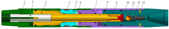
Figure 1.
Inserted tooth slip packer: (1) upper cylinder body, (2) limit teeth, (3) piston, (4) carbide teeth, (5) slip body, (6) slip seat, (7) middle cylinder body, (8) O sealing ring, (9) lower cylinder body, (10) limited ball sleeve, (11) steel ball, (12) spring, (13) screw.
The drilling pump is opened when the tool reaches the predetermined sidetracking position. The drilling fluid enters the upper surface of the piston and the upper surface of the lower cylinder body through the stopped teeth. Between the upper and bottom parts of the ball valve sleeve orifice a throttle pressure difference is formed which pushes the ball valve sleeve downward and, as a result, it comes into contact with the ball, and then continues to lower the compression spring for pressure suppression. The stopped tooth–piston–cylinder body moves downward with the thrust of the double cylinders. The four slips are pushed outwards gradually with the push of the piston’s inclined plane, and the cemented carbide teeth of the slip contacts with the inner wall of the casing and feeds into it, hence achieving axial and circumferential fixation. As the stopped teeth cannot be restored to their original position, the slip teeth do not retract at the time of feeding into the casing wall so as to achieve a reliable setting. A clear tooth indentation will be left on the surface of the casing by the cemented carbide teeth of the slip, as shown in Figure 2.
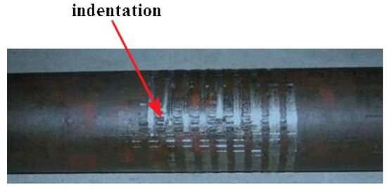
Figure 2.
Indentation on the surface of the casing.
3. The Effect of Furrow Action
When a rough, hard metal surface slides on a soft metal surface, it leads to a plastic deformation and a groove which generates a channel resistance that is called furrow resistance or furrow effect, as the hard micro-bulge is pressed into the surface of the soft metal [15]. For the ideal elastic–plastic material, in most cases without lubricants, the ratio of the furrow resistance of the micro-bulge to the shear resistance of the sticking point is very small and usually only accounts for a few percent of the total friction, which can be ignored. However, in some cases, such as the rough surface of hard metal sliding through the soft metal surface, the resistance generated by the furrow effect is the main component of friction, which cannot be ignored [16].
In the setting process of the inserted tooth slip sidetracking packer, the cemented carbide tooth will slide through the surface of the relatively softer P110 casing to produce the furrow, which can be simplified as a groove that has been furrowed by squeezing the soft material after pressing a solid rough cone into the surface of the soft material (as shown in Figure 3). Assuming that the projected area of the normal setting load support is A1, the projected area of the furrow groove is A2.
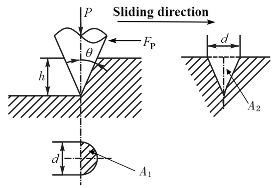
Figure 3.
Furrow model of layout of cone rough peak.
Suppose the plastic yield of soft metal to be isotropic, with the yield strength of σs, then:
Normal setting load:
Furrow friction resistance:
Furrow friction coefficient:
It can be learned from the calculation formula of the friction coefficient fp of the furrow that, as there are various furrow areas generated by various teeth shapes, the fp value also varies. For example: when the half cone angle θ = 60°, the result is fp = 0.32; when θ = 45°, the result is fp = 0.64; when θ = 30°, the result is fp = 1.1.
The above calculation of fp ignores the buildup of metallic material in front of the furrow of the cone tooth and the lateral ridges. Particularly, the occurrence of buildup increases the value of fp. Moreover, it is not entirely correct to assume that plastic yield is isotropic. Taking these errors into consideration, the expression of fp is multiplied by the correction factor kp, the kp values of common materials are shown in Table 1 [16].

Table 1.
Correction coefficient kp.
When taking the adhesive friction coefficient fa and furrow friction coefficient fp into consideration at the same time, the total friction coefficient f is:
f = fa + kp × fp
4. Numerical Simulation Analysis Based on Furrow Effect
4.1. Finite Element Simulation Model
Due to the geometry of the assembly model and the symmetry of the load bearing, the geometry model for the monolithic slip to contact the P110 casing is established (as shown in Figure 4) by taking the four symmetrically distributed slip structure packers used for the 139.7 mm casing window sidetracking as the study object. In this model, the outer diameter of the piston is 95 mm, the inner diameter is 50 mm, the slip wedge angle is 8°, and for the slip tooth setting parameters, refer to document [6]. The standard dimension for the selection of T105 cemented carbide teeth, as well as the height of the teeth, are 2.5 mm; the surface area of the upper end of slip is 632 mm2. The material constants of the P110 casing are: elastic modulus E = 2.11 × 10⁵ MPa, Poisson’s ratio v = 0.26, density ρ = 7.87 g.cm−3, yield strength is 765 MPa, and compressive strength is 850 MPa. The ZD10U cemented carbide with material constants of elastic modulus E = 6.4 × 10⁵ MPa, Poisson’s ratio v = 0.22, density ρ = 15 g.cm−3, hardness HRA 90.2, bending strength 2600 MPa, and compressive strength 5.46 × 10³ MPa, is adopted for the cutting teeth.
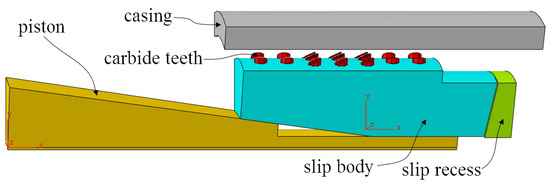
Figure 4.
Assembly model of single slip.
The hexahedral solid element C3D8R is used for the slip tooth and casing. The stress concentration may occur on the tip of the tooth; therefore, the mesh refinement with a mesh size of 1 mm is adopted, which satisfies the calculation requirements, according to the trial. A tetrahedral solid element C3D4 is adopted for the slip body and the piston. The meshed FEA model is shown in Figure 5, and the dynamic explicit analysis is adopted.
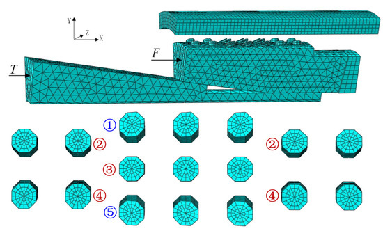
Figure 5.
Finite element model.
According to the actual working conditions of the sidetracking packer, the axial thrust force that is generated by the twin-cylinder under the 25 MPa hydraulic pressure is 306 kN. The setting load of each slip is T = 76.5 kN. After the setting process, the packer should bear 294 kN axial load without falling, so the axial load borne by each slip is F = 73.5 kN. The whole calculation process is divided into two load steps. The first step is casing fixation, which applies radial restraints to the piston, applies fixed restraints to the slip bowl, and applies the setting load of T = 76.5 kN to the upper end of the piston, so that the piston pushes the slips to move to the casing wall along the slip bowl to achieve the setting. The second step is to apply radial constraints to the slip and cemented carbide teeth, apply 73.5 kN axial load to the upper end face of the slip, and verify the reliability of the slip setting.
4.2. Taking No Account of the Furrow Effect
Taking no account of the furrow effect, the coefficient of friction between the slip tooth and the casing is only the adhesive friction coefficient fa = 0.28 [9]. After the setting process is completed by pressing the slip tooth into the casing wall, the slip tooth slides down along the casing wall under the effect of axial load, so that the plastic deformation will occur on the inner wall of the casing and five furrows will be plowed out, the furrow stress of the casing surface is shown in Figure 6. The furrow displacement of the casing surface is shown in Figure 7 and Figure 8, and the maximum furrow displacement reaches 3.09 mm. According to the analysis results, it is known that in the simulation analysis of the inserted tooth slip setting process, no reliable axial setting of the packer can be achieved without regard to fp.
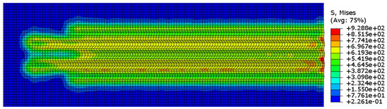
Figure 6.
The whole-tooth furrow stress.
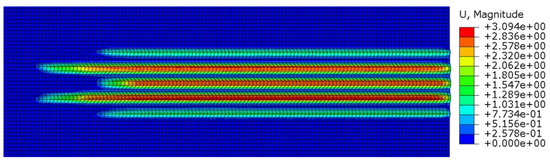
Figure 7.
The whole-tooth furrow displacement.
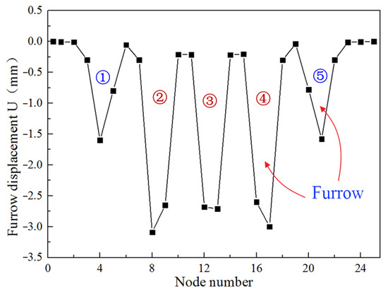
Figure 8.
Furrow section displacement of whole tooth.
The five furrows on the casing surface and the corresponding six lateral ridges are shown in Figure 9. The deepest furrow formed by five rows of slip teeth on the surface of the casing is 0.45 mm, and the shallowest is 0.4 mm. The highest ridges on both sides of the furrow reach to 0.4 mm, and the shortest ridge is about 0.3 mm. Therefore, during the analysis and calculation of the inserted tooth type slip setting, not only should the fp be taken into consideration, but the effect of the ridge on fp should also be considered. Namely, the correction coefficient kp should be introduced.
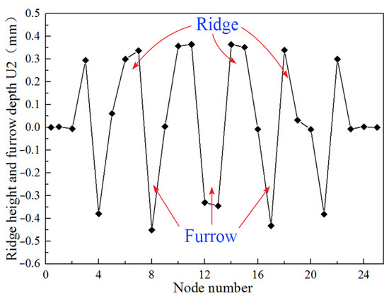
Figure 9.
Convex ridges height and furrow depth of whole-tooth furrow.
Figure 10 and Figure 11 show the furrow effect caused by different types of teeth such as spherical teeth, cone teeth, and T105 teeth. Different furrow effects are generated on the casing surface as the packer slips are inserted by different types of teeth, and the corresponding fp is different. Among these, the furrow effect generated by the T105 teeth is the strongest, followed by that of the cone teeth, and the furrow effect generated by the spherical teeth is the weakest. In general, the furrow effect is related to the sharpness of the slip teeth tip, and the sharper the tips of the teeth are, the more obvious the furrow effect is.
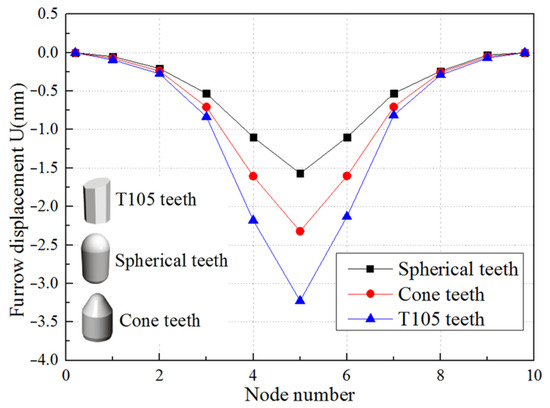
Figure 10.
Displacement of single teeth.
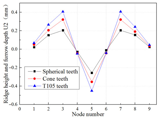
Figure 11.
Ridge height and depth of single teeth.
4.3. Considering the Furrow Effect and Adhesion Effect
According to the theory of adhesion proposed by Bikerman et al. [17,18], most of the friction surfaces are under plastic contact condition. Considering the furrow effect and adhesion effect between the friction surfaces of the slips and the casing, stimulation analysis of packer slip setting process are carried out once again, after the introduction of the furrow friction coefficient and the furrow friction correction factor. According to the analysis, fa = 0.28, fp = 0.54, kp = 1.35, the total friction coefficient f = fa + kp × fp. The simulation results are shown in Figure 12, Figure 13 and Figure 14. Figure 12 indicates the Von Mises stress distribution of 17 slip tooth, Figure 13 indicates the stress distribution of the casing surface, and Figure 14 indicates the strain distribution of the casing surface.
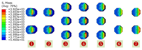
Figure 12.
The stress of slip tooth (before optimization).
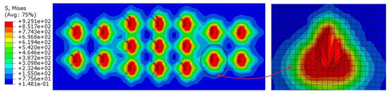
Figure 13.
The stress distribution of casing wall (before optimization).
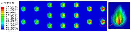
Figure 14.
The strain distribution of casing wall (before optimization).
It can be seen from Figure 12 that an axial load of 73.5 kN is applied on the upper end of the slips after the packer setting, and the maximum stress of some slip tooth tips reaches 3925 MPa. The average tooth tip stress was obtained on the basis of the result of the slip tooth FEA, and then the bending stress of 17 tooth tips was achieved by means of the beam-bending theory. It can be learned from the data in Table 2 that the maximum bending stress of the tooth tip is 2578 MPa, but is still less than the bending resistance of the ZD10U cemented carbide teeth, which indicates the safety and reliability of the packer slips teeth. At the same time, it is found that the maximum bending stress of the tooth tip has nearly reached the bending strength of the ZD10U carbide teeth with insufficient margin. Since the tooth stress is inversely proportional to the number of the slip teeth, the number of slip teeth arranged is optimal when the structure of packer slips designed in this paper is under constant working conditions, and when the working load increases it is necessary to increase the number of teeth in order to reduce the tooth stress.
Table 2.
Bending stress of the slip tooth tip.
It can be seen from Figure 13 that, after introduction of the furrow friction coefficient fp and the correction factor kp, the teeth of the slips feed into the casing wall to cause plastic deformation and form a uniform and distinct tooth indentation under the setting load T and the axial load F, that is consistent with the practical project (as shown in Figure 2). Additionally, the disconnection of the maximum stress area of each indentation, as well as there being no groove ploughed out on the surface of the casing, indicates that the slip does not slide down and the packer has achieved a reliable setting.
5. Orthogonal Optimization Analysis of Slip Structure and Experiment Study
5.1. Orthogonal Optimization Analysis of Slip Structure
According to the simulation data in Figure 12 and Table 2, it can be seen that all teeth on the slip have uneven forces and different biting depths, and there are great differences, as shown in the red curve in Figure 15, and the number of the teeth is shown in Figure 12. There are many factors affecting the uniformity of the depth of the slip teeth, such as the number of cemented carbide teeth installed, the diameter of the spacing of the installed cemented carbide teeth, the wedge angle of the slips, the installation angle of the cemented carbide teeth, the number of slips, the stability of the setting load of the packer, and whether the machining and installation of the slips are standard. In order to solve the uniformity of bite depth and improve the overall setting performance of the sidetracking packer, the orthogonal optimization analysis of the structural parameters of the sidetracking packer was carried out on the basis of the furrow effect [19,20,21].
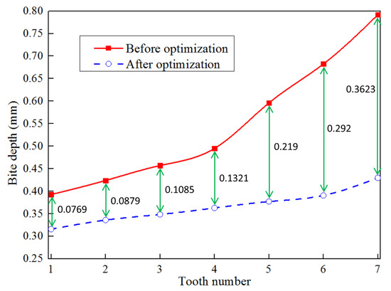
Figure 15.
Distribution of bite depth of each tooth.
According to the design requirements of the sidetracking packer slips, four factors that have a significant impact on slip performance, including slip tooth installation spacing L (factor A), the slip tooth installation angle α (factor B), the slip tooth diameter d (factor C), and the slip wedge angle β (factor D), are selected for the orthogonal test [22,23], and their parameters are shown in Figure 16. According to the principle of orthogonal test [24,25,26], a four-factor and three-level orthogonal test scheme L9 (34) [27,28] was designed. The test parameters are shown in Table 3 to explore the influence rule of these four test factors on the slip performance of sidetracking packer.
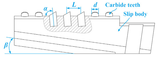
Figure 16.
Slip structural parameters.
Table 3.
Orthogonal test scheme.
Numerical simulation is carried out on slips of nine different schemes under setting load (T = 76.5 kN) and axial load (F = 73.5 kN) conditions. The variation law of bite depth of slip teeth under nine different schemes is shown in Figure 17. The numerical simulation results of the orthogonal test are shown in Table 4. The standard deviation of the data of each bite depth of the slips into the casing was used as the standard to measure the uniformity of each bite depth. As can be seen from Figure 17, the bite depth of the slip teeth in scheme 4 and scheme 7 is relatively large, and the bite depth of each tooth in scheme 4 varies greatly. The bite depth of the tooth from #1 to #7 increases significantly, and the bite depth of #7 is almost twice as deep as that of #1. The bite depth of slip teeth in scheme 2 and scheme 9 is relatively small.
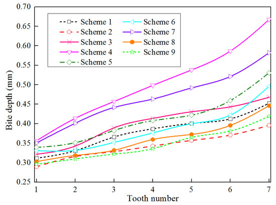
Figure 17.
The bite depth of slip tooth in different schemes.
Table 4.
Orthogonal test result.
Range analysis is also known as an intuitive analysis method and has the advantages of being simple to calculate, having intuitive imaging, being simple to understand, and so on. It is the most commonly used method for analyzing the results of an orthogonal test. Range analysis is converted into a single index orthogonal experimental design, and the larger the range, the greater the influence weight of the selected level under this factor on the test index [29,30]. According to the calculated data in the table, the influence of the four factor levels on the three test indicators can be obtained. Table 5 shows the range analysis results for the maximum stress of slip teeth; Table 6 shows the range analysis results for the maximum bite depth; and Table 7 shows the range analysis results for the uniformity of bite depth. According to the range analysis results, the influence of maximum stress on alloy teeth is D > A > B > C, from large to small; the influence of maximum bite depth is A > B > D > C, from large to small; and the influence of bite depth uniformity is A > B > C > D, from large to small.
Table 5.
Range analysis of maximum stress of slip tooth.
Table 6.
Range analysis of maximum bite depth.
Table 7.
Range analysis of bite depth uniformity.
Therefore, the optimal combination analysis results of objective functions are shown in Table 8.
Table 8.
Optimal combination of objective functions.
Through orthogonal test analysis, it is found that the optimal combination of the two optimization objective functions [31,32,33]—the optimal uniformity of bite depth and the optimal stress of slip tooth—is consistent. Therefore, the optimal combination parameters of slips can be obtained as follows: the slip tooth installation spacing L = 10 mm, the slip tooth installation angle α = 80°, the slip tooth diameter d = 10 mm, and the slip wedge angle β = 6°. This set of slip parameters does not appear in the orthogonal test scheme in Table 3, so another set of simulation tests needs to be added. The simulation result for the optimal slip combination parameters is shown in Figure 18. As can be seen from Figure 18, the maximum stress of the slip teeth decreases from 3925 MPa to 3219 MPa, with a percentage of 17.99% decrease, and the stress distribution of each tooth is relatively uniform. By comparing Figure 14 and Figure 19, it can be seen that the bite depth of each tooth, when it bites into the casing before optimization, is unevenly distributed. The bite depth above the casing is small, while the bite depth below the casing is large. After optimization, the shape and bite depth of each tooth are basically the same. Meanwhile, as can be seen from Figure 15, the bite depth of each tooth after optimization is significantly reduced compared with that before optimization, but the change range of the bite depth of each slip tooth is small, and the standard deviation of the bite depth uniformity of each slip tooth is reduced from 0.1366 to 0.0349, which is 74.45% lower than that before optimization.
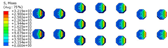
Figure 18.
The stress of slip tooth (after optimization).
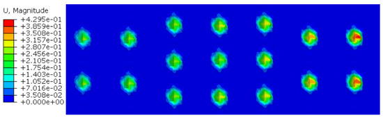
Figure 19.
The strain distribution of casing wall (after optimization).
5.2. Experiment Study
In order to verify the accuracy of the furrow effect and the simulation results, in the case study of Sidetracking Well 2, Block Wen 116, Zhongyuan Oilfield in China, the inserted tooth slip sidetracking packer is employed to carry out the experiment on the casing with a diameter of 139.7 mm, steel grade of P110, and wall thickness of 7.72 mm, as shown in Figure 20. The purpose of the experiment is to verify the reliability of the setting process of the inserted tooth slip, and to observe whether the slip will slide down. The basic parameters of the experiment include a set pressure of 25 MPa, total load time of 220 s, and total WOB of 310 kN. The loading time history is shown in Figure 21.
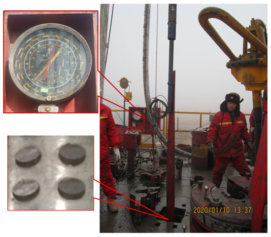
Figure 20.
Setting experiment of inserted tooth slip sidetracking packer.
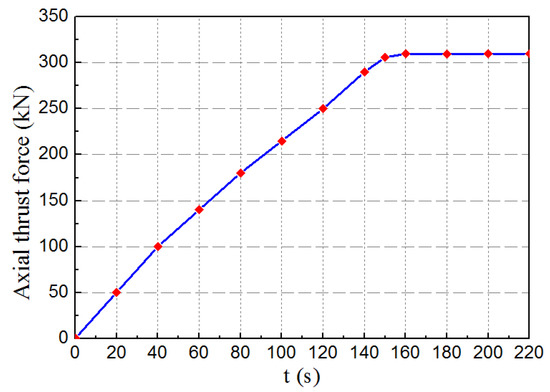
Figure 21.
Loading time history.
The application test indicates that the inserted tooth slip sidetracking packer does not slide down and has achieved a reliable setting. The application test results also show that the FEA model and calculated results of the inserted tooth slip sidetracking packer, considering the furrow effect and the adhesion effect, are correct in this paper and that the requirements of engineering applications are basically met. Therefore, in the theoretical research and simulation analysis of the slip, the furrow effect and the adhesion effect between the friction surfaces of the slips and the casing need to be considered at the same time.
6. Conclusions
According to the above analysis and experiment, the following conclusions can be made:
- (1)
- In the FEA and calculation of the setting process of inserted tooth-type slip, it is not only necessary to consider the furrow friction coefficient fp, but also the effect of the ridge on the furrow friction coefficient fp, which requires the introduction of correction factor kp.
- (2)
- The corresponding furrow friction coefficient fp varies according to the different furrow effects occurring on the casing surface caused by the various types of teeth inserted on the packer slips. The furrow effect is related to the sharpness of the tooth tips of the slips. The sharper the tooth tips are, the more obvious the furrow effect is.
- (3)
- Under the dual effects of the furrow effect and the adhesion effect, the teeth of the slip feed into the casing wall to produce a uniform and distinct indentation, and the disconnection of the maximum stress area of each indentation, as well as the safety and reliability of all carbide teeth, realize the reliable setting of the packer.
- (4)
- Through orthogonal experiments, the optimal combination parameters of the slips were obtained by taking the optimal bite depth uniformity as the objective function: slip tooth installation spacing L = 10 mm, slip tooth installation angle α = 80°, slip tooth diameter d = 10 mm, and slip wedge angle β = 6°. The standard deviation of bite depth uniformity of the optimized slip teeth is 74.45% lower than that before optimization.
Author Contributions
Conceptualization, Q.W.; methodology, C.K.; software, Q.W.; validation, Y.L.; formal analysis, W.F.; investigation, M.Y.; resources, R.T.; data curation, W.F.; writing—original draft preparation, Q.W.; writing—review and editing, C.K.; supervision, C.K.; project administration, R.T. All authors have read and agreed to the published version of the manuscript.
Funding
This research was funded by [Project of Sichuan Science and Technology Department] grant number [2022NSFSC1273], and [Development of open hole window sidetracking packer for air drilling] grant number [212322].
Data Availability Statement
No new data were created or analyzed in this study. Data sharing is not applicable to this article.
Conflicts of Interest
The authors declare no conflict of interest.
Nomenclature
| A1 | is the projected area of the normal setting load support surface |
| A2 | is the projected area of the furrow groove, as shown in Figure 3 |
| P | is the normal setting load |
| FP | is the furrow friction resistance |
| σs | is the yield strength |
| fp | is the furrow friction coefficient |
| θ | is the half-cone angle |
| kp | is the correction factor |
| fa | is the adhesive friction coefficient |
| T | is the setting load of each slip |
| F | is the axial load borne by each slip |
| f | is the total friction coefficient |
| L | is slip tooth installation spacing, as shown in Figure 16 |
| α | is the slip tooth installation angle |
| d | is the slip tooth diameter |
| β | is the slip wedge angle |
References
- Kong, C.; Zhang, D.; Liang, Z.; Cai, R. Mechanical analysis of drill bit during dual-casing sidetracking. J. Pet. Sci. Eng. 2017, 159, 970–976. [Google Scholar] [CrossRef]
- Campbell, J.M.; Gregurek, P.; Swadi, S.N.; Dewey, C.; Desai, P. New tools and procedures increase reliability of openhole sidetrack operations. In Proceedings of the SPE Eastern Regional Meeting, Columbus, OH, USA, 17–19 August 2011. [Google Scholar]
- Orodu, O.D.; Tang, Z.; Anawe, P.A. Sidetrack and recompletion risk evaluation—Waterflooded reservoir. J. Pet. Sci. Eng. 2011, 78, 705–718. [Google Scholar] [CrossRef]
- Okogbe, B.; Orimoloye, S.; Adewale, O.; Avanoma, E.; Alikor, E.O.; Papuc, V. Cased Hole Section Milling And Under Reaming Operation In Converting Oil Well Into A Water Disposal Well, Onshore Amukpe Oil Field. In Proceedings of the SPE Nigeria Annual International Conference and Exhibition, Lagos, Nigeria, 5–7 August 2013. [Google Scholar] [CrossRef]
- Chen, Y. Development and application of a new double-slip hpht liner hanger. Nat. Gas Ind. 2010, 30, 48–50. [Google Scholar]
- Zhang, D.R.; Li, D.; Kong, C.Y. Design of new-pattern sidetracking setting tool and finite element analysis for slips. Oil Field Equip. 2012, 41, 69–71. (In Chinese) [Google Scholar]
- Wu, K.S.; Xie, B.; Yang, X.K. 3-D fea of contact for slip system of packer systems. Oil Field Equip. 2005, 34, 47–49. (In Chinese) [Google Scholar]
- Wang, Z.J.; Deng, W.D.; Lin, Z.C.; Shang, X.; Wang, Y. Finite element analysis and structure improvements of packer slip in horizontal wells. Oil Drill. Prod. Technol. 2013, 35, 78–81. [Google Scholar]
- Wu, E.C. Mechanical Analysis & Experimental Research on Valvular Slip; Daqing Petroleum Institute: Daqing, China, 2007. (In Chinese) [Google Scholar]
- Wang, D.; He, S.P.; Zhang, X. A study on contact stress of packer slip. J. Exp. Mech. 2006, 21, 351–356. [Google Scholar]
- Chen, Y.; Tan, J.; Xiao, G. Investigation on the Depth of Slip Hanger Teeth Bite into Casing and the Mechanical Properties of Casing under Different Suspension Loads in Ultra-Deep Wells. Stroj. Vestn. J. Mech. Eng. 2021, 67, 516–524. [Google Scholar] [CrossRef]
- Persson, B. Influence of frozen capillary waves on contact mechanics. Wear 2008, 264, 746–749. [Google Scholar] [CrossRef]
- Bharat, B.; Jacob, N.I.; Uzi, L. Nanotribology: Friction, wear and lubrication at the atomic scale. Nature 1995, 374, 607–616. [Google Scholar]
- Xie, Z.F.; Yu, J.X.; Qian, L.M. Load effect on the translation of friction mechanism of four materials. J. Shanghai Jiaotong Univ. 2009, 43, 1930–1935. (In Chinese) [Google Scholar]
- Gao, S.Z.; Xu, G.B. Sliding-friction coefficient calculation method of plane-gate walk supporting. J. Tianjin Univ. 2014, 47, 383–388. (In Chinese) [Google Scholar]
- Zhou, X.R.; Yang, Q.M. Friction, Wear and Lubrication; Petroleum Industry Press: Beijing, China, 1997. (In Chinese) [Google Scholar]
- Wen, S.Z.; Huang, P. Tribological Principles; Tsinghua University Press: Beijing, China, 2008. (In Chinese) [Google Scholar]
- Bikerman, J.J. Ploughing and Adhesion of Sliding Metals. J. Appl. Phys. 1943, 14, 436. [Google Scholar] [CrossRef]
- Huynh, N.T.; Nguyen, T.V.T.; Nguyen, Q.M. Optimum Design for the Magnification Mechanisms Employing Fuzzy Logic–ANFIS. Comput. Mater. Contin. 2022, 73, 5961–5983. [Google Scholar] [CrossRef]
- Wang, C.-N.; Yang, F.-C.; Nguyen, V.T.T.; Vo, N.T.M. CFD Analysis and Optimum Design for a Centrifugal Pump Using an Effectively Artificial Intelligent Algorithm. Micromachines 2022, 13, 1208. [Google Scholar] [CrossRef]
- Pal, M.; Mandal, N.K.; Aggarwal, M.L. A-optimal designs for optimum mixture in an additive quadratic mixture model. Statistics 2017, 51, 265–276. [Google Scholar] [CrossRef]
- Sun, Y.; Li, C.; You, J.; Bu, C.; Yu, L.; Yan, Z.; Liu, X.; Zhang, Y.; Chen, X. An Investigation of the Properties of Expanded Polystyrene Concrete with Fibers Based on an Orthogonal Experimental Design. Materials 2022, 15, 1228. [Google Scholar] [CrossRef]
- Chen, S.; Jin, E.; Xu, G.; Zhuo, S.; Chen, X. Factors Influencing the Low-Temperature Properties of Styrene-Butadiene-Styrene Modified Asphalt Based on Orthogonal Tests. Polymers 2023, 15, 52. [Google Scholar] [CrossRef]
- Li, J.; Su, W.; Zhang, Z.; Guan, Z.; Li, J.; Wang, J. Design and Numerical Study of Argon Gas Diversion System Using Orthogonal Experiment to Reduce Impurities in Large-Sized Casting Silicon. Crystals 2022, 12, 562. [Google Scholar] [CrossRef]
- Liu, K.-P.; Niu, X.-B.; Zhang, Y.-D.; Ji, Z.-C.; Feng, J.-Y.; Li, W.-Q. Key design parameters and optimum method of medium- and high-velocity synchronous induction coilgun based on orthogonal experimental design. Chin. Phys. B 2019, 28, 024102. [Google Scholar] [CrossRef]
- Cai, C.; Kang, Y.; Wang, X.; Hu, Y.; Chen, H.; Yuan, X.; Cai, Y. Mechanism of supercritical carbon dioxide (SC-CO2) hydro-jet fracturing. J. CO2 Util. 2018, 26, 575–587. [Google Scholar] [CrossRef]
- Fan, H.; Zhang, J.; Zhang, W.; Liu, B. Multiparameter and Multiobjective Optimization Design Based on Orthogonal Method for Mixed Flow Fan. Energies 2020, 13, 2819. [Google Scholar] [CrossRef]
- Xu, C.; Nie, W.; Yang, S.; Peng, H.; Liu, Z.; Ma, Q.; Guo, C.; Liu, Q. Numerical simulation of the multi-index orthogonal experiments on the spray dust-settling devices. Powder Technol. 2020, 371, 217–230. [Google Scholar] [CrossRef]
- Quan, H.; Guo, Y.; Li, R.; Su, Q.; Chai, Y. Optimization design and experimental study of vortex pump based on orthogonal test. Sci. Prog. 2020, 103, 0036850419881883. [Google Scholar] [CrossRef]
- Han, X.; Zhao, S.; Liu, C.; Chen, C.; Xu, F. Optimization of geometrical design of clinching tools in clinching process with extensible dies. Proc. Inst. Mech. Eng. Part C J. Mech. Eng. Sci. 2017, 231, 3889–3897. [Google Scholar] [CrossRef]
- Shu, Q.-Y.; Wang, X.-P. Orthogonal complements and extending orthogonal subsets of semimodules. Linear Multilinear Algebra 2021, 1–19. [Google Scholar] [CrossRef]
- Yang, X.; Liu, G.; Li, Y.; Gao, S. Structural Optimization of Reciprocating Seal with Magnetic Fluid Based on Orthogonal Test Design. J. Magn. 2021, 26, 229–237. [Google Scholar] [CrossRef]
- Sun, M.; Liu, W.; Liu, J.; Tang, P.; Hao, C. Adaptive Subspace Detection Based on Gradient Test for Orthogonal Interference. IEEE Trans. Aerosp. Electron. Syst. 2022, 58, 1868–1877. [Google Scholar] [CrossRef]
Disclaimer/Publisher’s Note: The statements, opinions and data contained in all publications are solely those of the individual author(s) and contributor(s) and not of MDPI and/or the editor(s). MDPI and/or the editor(s) disclaim responsibility for any injury to people or property resulting from any ideas, methods, instructions or products referred to in the content. |
© 2023 by the authors. Licensee MDPI, Basel, Switzerland. This article is an open access article distributed under the terms and conditions of the Creative Commons Attribution (CC BY) license (https://creativecommons.org/licenses/by/4.0/).