Abstract
Smart production systems conforming the Industry 4.0 vision are based on subsystems that are integrated in a way that supports high flexibility and re-configurability. Specific components and devices, such as industrial and mobile robots or transport systems, now pose full-blown systems, and the entire Industry 4.0 production system constitutes a system-of-systems. Testing, fine-tuning, and production planning are important tasks in the entire engineering production system life-cycle. All these steps can be significantly supported and improved by digital twins, which are digitalized replicas of physical systems that are synchronized with the real systems at runtime. However, the design and implementation of digital twins for such integrated, yet partly stand-alone, industrial sub-systems can represent challenging and significantly time-consuming engineering tasks. In this article, the problem of the digital twin design for discrete-event production systems is addressed. The article also proposes to utilize a formal description of production resources and related production operations that the resources can perform. An executable version of such formalization can be automatically derived into a form of a digital twin. Such a derived digital twin can be enhanced with operation duration times that are obtained with process mining methods, leading to more realistic simulations for the entire production system. The proposed solution was successfully tested and validated in the Industry 4.0 Testbed, equipped with four robots and a transport system, which is utilized as a use-case in this article.
1. Introduction
Contemporary production systems are typically designed according to a hierarchical layered architecture known as an automation pyramid, depicted in Figure 1. This well-proven architecture is focused on solid foundations of robust industrial components such as robots or other manipulators, sensors, transportation system components, providing process data inputs and outputs (I/Os). The second level in the automation pyramid is represented by programmable logic controllers (PLCs), implementing control algorithms providing basic functionality, handling interfaces between individual shop-floor components and guaranteeing safety of the integrated system. A more advanced coordination and production control is solved on the SCADA (Supervisory Control and Data Acquisition) system level of the automation pyramid. All these three aforementioned levels of the automation pyramid are tightly connected to the shop-floor hardware, but they also execute pre-coded production sequences tightly connected to produced goods/products. Even if the two upmost levels of the pyramid, that is, a manufacturing execution system (MES) and enterprise resource planning (ERP) systems are software-intensive and provide some degree of flexibility in the areas possibility to add, modify, or remove products or production processes related to producing these products, the bottom-most levels of the pyramid are not able to meet the flexibility as they are strictly tailored for predefined and pre-programmed production processes. This architectural and functional limitation is one of the most important contribution of paradigm shifts represented by Industry 4.0 and Smart Manufacturing.
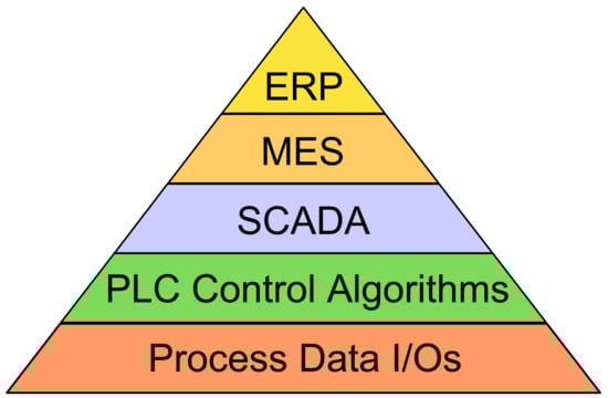
Figure 1.
Traditional automation pyramid, preceding architectures of cyber-physical production system conforming Industry 4.0 principles.
Industry 4.0 (The term “Industrie 4.0” was first publicly introduced in 2011 at the Hannover Fair http://www.wolfgang-wahlster.de/wordpress/wp-content/uploads/Industrie_4_0_Mit_dem_Internet_der_Dinge_auf_dem_Weg_zur_vierten_industriellen_Revolution_2.pdf (accessed on 14 February 2022)) and Smart manufacturing shifts in their engineering processes from the bottom-up design approach to top-down approach. As both emerging areas are rather visions than specific sets of requirements that can be checked-up when provisioning such a smart production system, the trajectories towards Industry 4.0 cyber-physical production systems [1] may be diverse and variously difficult.
The promising way how to push and adopt Industry 4.0 concepts for smart manufacturing is a shift from traditional shop-floor components towards more independent systems referred as Industry 4.0 components. The Industry 4.0 components [2] are equipped with well-defined interfaces, they are more inter-operable and stand-alone. In fact, they adopt basic principles of intelligent agents [3,4] in terms they are typically equipped with a basic knowledge about the environment where they act. However, on the other hand, they are not at all coordinating themselves or intentionally communicating with other agents, as intelligent agents can do. The communication of Industry 4.0 components and their coordination should be still done on higher levels of the automation system pyramid, however, neither the traditional SCADA systems nor the contemporary MES systems are capable to fully comply these required coordination requirements.
To meet the requirements on the runtime coordination of shop-floor devices, it is needed to plan production execution according to the latest state of the system and according to the current availability of resources and materials. Therefore, we are using production planner utilizing academic standard “Planning Domain Definition Language” (frequently abbreviated as “PDDL” and introduced in details later in Section 2.3), however, we need a digital twin [5] keeping the global state of the system as an enabler for planner-supported production execution.
The digital twin is a digital replica of the real physical system that captures and is able to provide the up-to-date information about the latest global state of the entire system, in the context of this article of the real industrial production system. The first concept of a digital twin was introduced by Dr. Michael Grieves in 2002 (cf. https://www.researchgate.net/publication/307509727_Origins_of_the_Digital_Twin_Concept (accessed on 14 February 2022)). In the last two decades, the concept of the digital twin has evolved and has matured into wide usage within various Industry 4.0 applications. The term “digital twin” is, however, frequently confused and misused with the term “simulation”, as it is explained in [5,6] due to the current trend of overall and unclear “digitalization” of production systems and processes. In the context of this article, simulation is an executable model for the real system, which however does not need to be synchronized with the real twin. In other words, the simulation model cannot be easily started without prior justification and fine-tuning of initial conditions according to the latest state of the real system. This fact complicates use of simulations for supporting decision-making at runtime, analysis of current behavior and other frequently needed tasks.
A clear explanation of the terms digital twins and simulations can be found in Kritzinger et al. [6]. It provides a classification of those virtualized artifacts into the following three categories, considering the level of integration: (i) digital models running either independently on the physical objects or just with a manual data exchange, (ii) digital shadows equipped within automatic data flow from physical object to the digital object, and (iii) digital twins featured by bi-directional data flow between physical and digital objects, see [6] for more details. The paper explains that only a minority of the approaches can be considered digital twins, equipped with the bi-directional data flows. Since the approach presented in this article utilizes such bi-directional data flows to and from the digital twin (especially for the production planning and scheduling purposes), the proposed way of digital twin usage perfectly fits to the highest category of digital twins that are formulated in [6]. In other words, the required continuous integration and synchronization of the digital and real twins conforms to the full-blown digital twin [7], rather than just a digital shadow [8].
If running systems are not yet available or the values cannot be reused from other comparable systems of the same class, then data from specialized domain tools have to be used. Since these domain-specific tools cannot provide data to entire integrated systems, it makes sense still to use the proposed approach combining the solid foundations of the formal system description and the estimated time constants from various sources.
In the proposed approach, production plans are planned for each production order/goal on-the-fly, based on the global state of the production system that is obtained from the digital twin. Such a solution brings higher flexibility in the areas of supporting to add or remove allowed products as well as available production resources as part of the production system/active recipes. The proposed solution can also support recovering from various errors, simply by re-planning current and ongoing production goals and appropriate recipes in case of a failure in the production system. The solution was thoroughly tested and evaluated in the Industry 4.0 Testbed facility, which is utilized as a use-case in this article. Results of the experiments convincingly prove efficiency and flexibility of the proposed solution.
2. Related Work
Current industrial production systems are pushed to provide new flexibility and re-configurability to be more efficient and capable to react on rapidly changing market. The terms Industry 4.0 and smart manufacturing are gaining importance.
2.1. Industry 4.0 and Smart Manufacturing
The term smart manufacturing is, especially in Europe, frequently related to the term “Industry 4.0” [1,9]. Industry 4.0 is a vision or strategy on shifting traditional industrial manufacturing facilities towards modern and flexible systems, benefiting especially from advances in the domain of Artificial Intelligence (AI). According to Etz et al., “smart manufacturing is realizing the idea and potential of Industry 4.0 in reality” [10]. Smart manufacturing is related to a new generation of Cyber-Physical Production Systems (CPPS) featured with data connectivity and artificial intelligence [11].
Transforming traditional production facilities towards Industry 4.0 and smart manufacturing is frequently a long-term process incorporating various process steps. A roadmap for this transformation is addressed in [12]. It emphasizes six pillars, called six gears: (i) Strategy, (ii) Connectivity, (iii) Integration, (iv) Data analytics, (v) Artificial Intelligence, and (vi) Scalability [12]. A review of existing industrial standards, which have the capability for supporting smart manufacturing and system automation can be found in [13]. One of the most prominent roles in smart manufacturing is data acquisition and data processing [14].
2.2. Digital Twins for Production Systems
Traditionally, digital twins are defined in a domain-specific way that relies on a mathematical–physical description resulting from specific spatial shapes, materials, and physical phenomena/equations, see for example machining processes for high-tech/aerospace industry [15,16]. To simplify the design process of digital twins, generation of digital twins from 2D and 3D CAD plans/models is addressed in [17], by means of generating graphs from available plans/models that pose a basis for graph matchmaking. This approach has been slightly improved, generalized, and matured in [18], targeting generation of digital twins for brown-fields production systems in general, yet considering piping and instrumentation diagrams still as a use-case. The use of AutomationML can support design of the digital twin and make their design process more efficient and easier [19].
A clear separation of product, process, and resource aspects in production system automation and respective digital twin components is addressed in [20]. The utilized multi-agent paradigm is capable to inherently distinguish among these components of the production system engineering clearly. Despite the promising divide-and-conquer feature of multi-agent design paradigm, which could on one hand provide better flexibility, re-configurability and maintainability, on the other hand, the increased level of communication across all components and the overall coordination of software agents can be costly from the perspective of computation and messaging time and resource allocation [21].
The complexity of emerging cyber-physical production systems (CPPS) is significantly increasing, compared to traditional manufacturing systems. CPPS are systems-of-systems from the system and control theory point of view. Such a complexity of real systems implies increasing complexity of digital twins. One possible way out of the digital twin complexity is introducing a network of digital twins (e.g., corresponding to production line components), which can be however accessed and queried in a uniform way to get the entire coherent (global) state of the production system. Such a networked digital twin is addressed in [22]. Another approach facing the increasing complexity of systems is provided in [23]. It is focused on a digital twin architecture based on micro-services, whose communication is facilitated by a message-oriented middle-ware implemented by Apache Kafka, providing support for streamed data.
In terms of production planning, the application and integration of digital twins goes rather in the direction of a capacity planning. For example, supply chain planning is discussed in [24]. The use of a digital twin is not a new idea, but the innovation is to integrate/apply it for supply chain management, which is not done nowadays.
One of the research trends in the area of digital twins is their enhancement into a form of “cognitive digital twins”. The goal is to leverage digital twin features to fully realize Industry 4.0 visions. With Industry 4.0 components, sub-systems, and whole systems, various digital twins can be provided and available. They can be associated to individual components (and provided by component vendors) or to integrated (sub-)systems. Moreover, the very same part of the systems can be modeled with more than one digital twins, differing for example in their capabilities, precision, or simulation speed. Such twins are useful in various stages of production system life-cycle, nevertheless, it is useful to integrate multiple relevant digital twins and data to get all possible results. Cognitive digital twins are an emerging vision for realizing such integrated complex artifacts combining multiple digital twins and data. A reference architecture of a cognitive digital twin, based on the Reference Architectural Model for Industry 4.0 (RAMI 4.0), is proposed in [25]. To fulfill the aforementioned integration and cognitive features, semantic technologies (including ontologies and knowledge graphs) are utilized in [25] as potential solutions for realizing augmented cognitive capabilities. Even more advanced are “actionable cognitive twins”, which are enhanced not only with cognitive capabilities by knowledge models, but also provide more advanced insights and decision-making support to users [26]. Despite possible benefits of (actionable) cognitive digital twins, we are not using these paradigms in this article, because we perceive cognitive digital twins rather as a vision without open/standardized realization at this moment. The proposed approach in this article is on the digital twin level focused on the formalization of fundamental components/resources and their skills/operations that can be performed, as well as keeping the latest (formal) state of the real production system. Hence the proposed approach is rather light-weighted compared to the integrated structure of cognitive digital twins.
A systematic literature review on characteristics of digital twins is presented in Jones et al. [27]. It provides several notable viewpoints, including a Building Information Modelling (BIM) as a promising design paradigm that can cross borders of its origins in civil engineering (as it combines both physical and virtual entities with their data connections). A more traditional use of digital twin is coming from the area of model-based predictive control (MPC), inherently incorporating observation, filtering, and prediction applied for process control. Even though the systematic literature review [27] covers numerous aspects and viewpoints in a detailed way, it provides no formal-specification-based digital twins, which we have designed and implemented, and we propose it in this article.
2.3. AI Planning and Scheduling Based on PDDL
Artificial intelligence (AI) planning [28] belongs to the broad family of AI methods focused on a problem of finding a plan, that is, how to reach a specified goal/target state/condition from a defined initial/starting state. The plan is either a sequence of operations/actions or a graph of actions (usually describing operations over resources that can be executed in parallel) for a given domain. A formal specification of such a graph of actions can be represented according to the German standard VDI/VDE 3682 [29]. Information model for VDI/VDE 3682 is represented as an ontology in the Web Ontology Language (OWL, cf. https://www.hsu-hh.de/aut/forschung/forschungsthemen/ontology-engineering-for-collaborative-embedded-systems/ontology-design-patterns-for-the-manufacturing-domain/vdi-3682-formalized-process-description (accessed on 14 February 2022)).
In the planning domain, all allowed actions and their related constraints (i.e., preconditions and postconditions/effects) need to be formally specified. In the case of industrial production systems, the actions are frequently called production operations and sequences of production operations are called production processes from the perspective of the product-process-resource (PPR) distinction. In the context of formally specified information model for digital twins and manufacturing processes, a detailed insight is given in [30]. On the other hand, the paper does not bring automated derivation of production planning nor automatic control, which is addressed in this article with the use of PDDL problem formalization and demonstrated in the Industry 4.0 Testbed use-case.
In fully specified environments with complete domain knowledge available, planning can be pre-calculated off-line prior to the plan execution. In just partially specified or even dynamic environments (such as industrial production systems conforming Industry 4.0 design principles), the production plans need to be computed or at least revised/refined (according to the actual conditions) at runtime. The process of planning is usually realized with advanced path finding/branching algorithms, as it is commonly seen in artificial intelligence methods. AI planning incorporates various techniques such as path search algorithms with heuristics (One of the most well-known path search and a graph traversal AI algorithm that is still partially used by many nowadays AI planners is A* [31].), dynamic programming, machine learning, and SAT (boolean SATisfiability problem). Although automated planning itself is not quite new and it has been investigated for more than fifty years (e.g., a so-called STRIPS problem solver [32]), the continuous advances in mainly symbolic AI [33,34,35] and AI planning algorithms [36,37] make the planning approach ready for industrial-scaled systems [38].
The term planning refers to obtaining a sequence of actions, whereas scheduling (also known as capacity planning) is less concerned with “what” is being done and “why”, but more with “when” and “where”. A plan as a sequence of actions may (e.g., temporal planning) or may not (e.g., classical planning) cover dates and times, whereas a schedule most certainly will. The scheduling problem can be formulated as an optimization problem for processing a predefined finite set of actions/jobs in a system with limited/constrained resources. In scheduling, the arrival time for each job/action needs to be specified. Within the scheduling system, each job/action must typically pass several processing phases, depending on the specific conditions/constraints of the concrete scheduling problem. For each phase, the current occupancy of resources is given, as well as processing times depending on the resources used. Constraints on the processing sequence and jobs/actions are usually described by binary transitive anti-reflexive relations.
Given a formal description of the initial state of the system, a formal description of the goal state, and a formal specification of a set of possible actions, then the planning problem is to compute/create a plan that fulfills all constraints in its transition states and that satisfies all postulated goal conditions in its goal state.
For a formal specification of planning problem, several specialized computer languages have been developed. The well-known one is PDDL, which is supported by most of the state-of-the-art planners. We propose to use it also in this contribution. The planning problem in PDDL is divided into two specification files:
- 1.
- Domain description, which specifies all possible actions with their input parameters (list of parameter identifiers and their related types), preconditions (that must hold before a specific action begins), effects (specification of changes on state-space immediately after a specific action is finalized), and optionally more version specific properties like durations or costs.
- 2.
- Problem description, which specifies a concrete problem instance that contains description of the initial state and goal-state conditions.
A solution for a PDDL planning problem is a plan, a sequence of actions that are to be sequentially processed starting from the initial state of the problem, where, after successful processing of all actions, all the goal-state conditions of the planning problem are satisfied.
The language PDDL has been several times extended to support additional features enabling more advanced planning and scheduling. Explanations of such PDDL extensions including description of utilized techniques in solvers is summarized in [39]. The latest version of the language is PDDL 3.1 [40], but there exist numerous variants/extensions that support various features like ontologies, probabilistic effects, numbers and goal-achieved fluents, durative actions (temporal/parallel planning), explicit problem decomposition (multi-agent planning) and many others.
2.4. Production Planning for Industrial Production Systems Enabled by Digital Twins
Production processes in automated production systems are required to be changed, updated, and evolved during the entire production system life-cycle, which implies that the software components and codes have to evolve accordingly [41]. Automated generation of simulation models for control code tests is addressed in [42], nevertheless, this poses just a small piece in the overall design process activities mosaic. In this article, the proposed approach is focused on utilization of production planning and execution of production plans on hardware components with implemented minimalistic set of production operations (such as robotic operations pick and place, or transportation system operation move) that are generic, parameterizable, and re-usable across various production scenarios (and thoroughly tested just once and not separately for pre-coded scenarios as it has to be done in traditional approaches).
An application of PDDL for industrial problems including their formalization is addressed in [43]. It provides a collection of simple prototypical cases. In comparison to [43], the solution discussed in this article is more focused on industrial-scaled systems (The industrial-scaled system is considered a system that contains enough typical components running in real production environments, in our case (see Section 4) the system includes four robots and five workstations of a transport system with six autonomous shuttles, inter-connected by OPC UA communication). Furthermore, we are utilizing PDDL not only for isolated/off-line planning, but in the tight integration with the digital twin, that is, the resulting solution poses just one smart production planning and execution system.
The solution presented in this article is built on top of our long-term research in the areas of an advanced planning utilizing PDDL, combined together with a new generation of MES systems. The first proposal for goal-oriented MES based on PDDL planning is addressed in [44]. It already includes a concept of integrating a digital twin, however, this initial concept is not described there in details. In addition, the contribution presented in the original paper has not utilized (i) the data format AutomationML to support specification of engineering artifacts description nor (ii) assignment of durations to production operations in order to utilize the digital twin as a simulation model. Last but not least, the original paper [44] did not apply process mining to analyze and reconstruct production processes especially in the context of mining time-durations of production operations as we discuss later on in this article.
A tight coupling of production system models and the language PDDL is addressed in one of our previous works presented in [38]. A set of rules for the conversion of production system feature model into planning domain and planning problem specifications was proposed. Experiments conducted in [38] proved that even fully automated planning and re-planning is feasible, if available models provide enough pieces of information. The scientific backbone of the approach was based on the set of methods, tools, and formal abstractions referred as model-driven software engineering. It enables complex transformations of data among various data models by introducing abstract description models for all data or engineering artifacts. This approach was subsequently enhanced in [45] with more advanced features of PDDL, namely with “durative actions”. They support assigning virtual time-durations to PDDL actions/production operations. This ability shifted production planning more towards the area of production scheduling. The solutions for the planning problems had a very high quality in sense of their total duration time because parallelisms of concurrent production operations with their individual durations across multiple resources were considered directly inside the specialized PDDL planner. On the other hand, the computational complexity was extremely increasing with the size of the domain and problem. In fact, this extension was suitable rather for small-size (Details about concrete sizes of problems and domains and corresponding computation time required for finding a solution are evaluated and discussed in [45]). In other words, the durative action extension was computationally over-costly for industrial problems even of the size of the Industry 4.0 Testbed. Based on this experience, we are no longer using the durative action extensions anymore.
Modeling and incorporating inaccuracy and uncertainty in production planning and control is addressed in [46]. The information uncertainty is modeled and tackled with fuzzy logic. Uncertain information does not need to be excluded from further decision-making and planning/control processes, but it can still be utilized (even if the specification does not meet requirements on fully specified environments expected by PDDL, the fuzzy-logic-based approach can mitigate such uncertainty). Efficiency of the utilization of the digital twin for reconfiguration processes is described in [47], demonstrating that the use of digital twins is beneficial. Complexity of production systems together with increasing dynamics in some cases leads to use of decentralized system architectures [48]. A graph-based process planning and multi-agent orchestration based on multi-agent system paradigm is addressed in [49].
Various roles of digital twins are discussed in [50]. On the market exist domain-specific simulation models, such as robot vendor-specific simulation tools. An example of rather a vendor-neutral simulation tool is Siemens/Tecnomatix Process Simulate. A more generic and shifted towards a factory point of view is for example Siemens/Tecnomatix Plant Simulation. Both these tools belong to the family of Siemens PLM (Product Lifecycle Management) Software. Typically, such simulations are created manually, with the use of existing plans of production plans and other engineering documents or specifications. In some state-of-the-art cases, the simulation can be created automatically, cf. [51], where genetic algorithms are used.
To represent taxonomies and systems, numerous paradigms can be utilized. A prominent way plays a neutral and vendor-agnostic data format AutomationML. This data format is highly suitable for the purpose of the Asset Administration Shell [52,53], but it is not limited for this area. AutomationML provides standardized ways for representing system structures and together with semi-standardized recommendations and best-practices maintained by the AutomationML Office it is a very powerful “tool” for supporting system engineering and data exchange among engineering tools. It is an enabler for digitalized engineering of systems as well as their simulations and digital twins. However, the data format does not provide explicit support or recommendations for formal specification of the system behavior. Therefore, the data included in AutomationML cannot be directly utilized for the design of the formal digital twin that is required in this article, but the information contained in AutomationML can be efficiently utilized for translating PDDL actions and OPC UA (OPC Unified Architecture (UA) overview is online: https://opcfoundation.org/about/opc-technologies/opc-ua/ (accessed on 14 February 2022) and discussed in detail in [54]), and the translation of PDDL actions to OPC UA variables is shown in [55].
The AI is mainly used on the level of planning and scheduling algorithms in this article. The problem is the size of the state space, resulting from branching the problem. The AI techniques reduce the search space significantly and can optimize the search trajectories to avoid unwanted stuck in local subproblems. In a broader sense, the entire approach of automated AI planning based on the current (observed) state of the real system can be considered an AI-supported approach for industrial automation.
2.5. Synopsis
Although production planning and re-planning should be integral parts of Industry 4.0 and smart manufacturing production systems, support from industrial tool vendors is still quite limited. One of the most advanced company in this area is considered Siemens and its MES system called Opcenter (supporting also OPC UA communication with shopfloor machinery, cf. https://www.plm.automation.siemens.com/global/en/products/manufacturing-operations-center/ (accessed on 14 February 2022)), Preactor/Opcenter APS for manual/semi-automated capacity/strategic planning and scheduling (without any advanced AI support yet, cf. https://www.plm.automation.siemens.com/global/en/products/manufacturing-operations-center/preactor-aps.html (accessed on 14 February 2022)), and Process Simulate (cf. https://www.plm.automation.siemens.com/en_gb/Images/7457_tcm642-80351.pdf (accessed on 14 February 2022)) prepared partially for digital twinning of pre-defined supported components, especially in conjunction with SIMATIC S7-PLCSIM Advanced (cf. https://support.industry.siemens.com/cs/document/109795016/simatic-s7-plcsim-advanced-v4-0-trial-download?dti=0&lc=en-WW (accessed on 14 February 2022)). However, this solution strongly relies on company-specific components (vendor lock-in), support of open standards is limited (i.e., declared, but significantly constrained to subparts of standards or limited sets of data, such as AutomationML import/export in TIA portal). An exception is OPC UA, whose support is on a high level compared to other industrial-automation companies. On the other hand, OPC UA support is strong on a software stack level that are available in various maturity levels and under corresponding licenses from various software-oriented companies. There are numerous industrial standards, such as AutomationML, which are helpful, but their available tool support is still limited.
The situation is slightly better in academic/research world, providing better support especially for virtualization and digital twins. As well, open languages and solvers are available for planning (such as PDDL and respective solvers such as Fast Downward). Nevertheless, the state-of-the-art approaches still resemble rather isolated islands in the whole mosaic. The approach proposed in this article tries to provide one coherent view on the integrated system, which is successfully applied in the Industry 4.0 Testbed and which can be leveraged to industrial-scale level.
The proposed method is an attempt to utilize and to support open standards, such as OPC UA for shop-floor machinery communication, PDDL for planning domain and problem specifications, AutomationML/XML for system configuration and last but not least OpenXES for production logging and production process analysis by means of process mining [56,57] (XES is an open standard for storing and managing event log data, cf. https://www.xes-standard.org/openxes/start (accessed on 14 February 2022)). Digital twins are frequently perceived just as digital shadows or not-synchronized/offline simulations for the real system in other applications. To fulfill the vision of Industry 4.0, the proposed approach emphasizes to close the automation/production planning loop via a fully synchronized digital twin, which is also an integral part of the production system runtime.
Last but not least, the proposed approach, on the contrary to related works, poses a light-weight solution based on a relatively simple formal specification, whose creation is significantly less demanding (compared to traditional methods starting at complex CAD/CAM models) in terms of needed development time and effort.
3. Methods and Results
Currently, production systems are decomposed into smaller/atomic parts that are individually addressed and programmed by engineers of specific engineering domains, such as PLC programmers, robot programmers, mechanical engineers, and so forth.
The significant part of the description of a production system is only implicit, included in the artifacts of domain engineers. Only the minor part of the system description is explicitly represented in informal/human-readable documents such as CAD (Computer-Aided Design) plans, requirement specifications, ladder-logic diagrams, UML (The Unified Modeling Language) schemas, or high-level data flows/pipelines. Thanks to the setup, a large variety of technical details have to be discussed and resolved during the design-time as well as runtime. This process is frequently called round-trip engineering and it is focused on iterative improving of technical and implementation details until the entire system is reliable enough to meet the customer/production standards. Furthermore, it is very difficult to keep up-to-date global state of the entire production line. Due to this fact, any change or deviation in the production needs the complete re-initialization of the production line into the well-known initial state. Despite the fact that the majority of components do not need such a time-demanding re-initialization, current industrial processes are strictly relying on the full initialization because it reduces number of unintended system states, otherwise, the entire system design would be too complicated and difficult to test and debug.
To avoid numerous misunderstandings and inefficiencies in the current round-trip engineering during production system engineering, this article proposes a new approach for industrial production system automation engineering that is based on the formal description of the system and its components, which is subsequently used as a basis for the digital twin utilized at runtime. The proposed engineering/design process follows the further method steps:
- 1.
- Creation of the formal description of the entire production line from the system component perspective. Such a formal description is computer-understandable. It has to include description of all relevant system components, from which the production line consists. As well, all relevant connections of these components have to be annotated according to the real topology of the production system.In the Industry 4.0 Testbed use-case, we created several domains and their corresponding problem descriptions, namely a robotic domain (including used types of robots, source place and precise position, target place and precise position, item description that is manipulated) robotic operations pick and place, and Montrac transportation system domain (including initial and target positions of shuttles, commands for locking positioning units, etc.), as it is illustrated in Figure 2. Then we merged (shared predicates needs to be manually resolved) both of them together to obtain one final description of the entire production line.
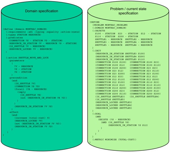 Figure 2. An example of a domain specification (on the left-hand side) and a problem specification (on the right-hand side) in PDDL. The problem specification is utilized and updated in the digital twin to keep the current global state of the production system. The topology of connections that is described in the problem specification directly corresponds to the topology of the Industry 4.0 Testbed production line depicted later on in Section 4 in Figure 7.
 - 2.
- Specification of feasible, referential transparent (in sense, that descriptions of operations do not contain any unspecified functional side effects) operations of all components. Each such generic parameterizable action/operation includes pre-conditions that have to be satisfied when starting to perform the operation and also effects/post-conditions that change the global state after performing the operation.In the PDDL notation, the following specifications have to be defined: actions including their parameters, as well as their preconditions and effects. To do so, declarations and instantiations of types, constants, and predicates is needed as well.In the Industry 4.0 Testbed use-case, all preconditions were specified and the manual check of feasibility and referential transparency in effects over the entire production line description was done.
- 3.
- Specification of initial state of the entire system. On the contrary to the current interpretation of the initial state, which is required during/after each production batch, the initial state in this process step is rather the very first state when making the system up-and-running for the first time. All the necessary changes for the next run are contained implicitly in the global state of the system represented in the digital twin, and thus it is not needed to reach initial/home positions of all components regularly during the production anymore. Information about material warehouses and buffers in terms of quantities and locations of specific pieces of material is a part of the initial state specification.In the Industry 4.0 Testbed use-case, this specification was encoded into the entire problem description in a spirit of Figure 2 example on the right-hand side of the figure.
- 4.
- Specification of various sensors and pattern-recognition systems attached. In the Industry 4.0 Testbed use-case, we are not using any specific sensor or an advanced vision/pattern recognition system so far. The only feedback used was a OPC UA operation-completion boolean flag, returned from components such as robots and transportation system shuttles. If the operation is not finalized successfully, then the execution of a plan is stopped and user intervention is expected. In specific cases (like mechanically blocked shuttle in a station or communication error with a specific robot arm), our system could automatically replan a new plan even without human supervision.
- 5.
- Mapping the aforementioned specifications to an AutomationML configuration file. The AutomationML file is utilized as a single unique system setup. It has to include information about all communication endpoints (i.e., URL of each endpoint, ways of authentication), data structures accessible via those endpoints. In addition, the AutomationML configuration file has to include mappings between PDDL actions and communication interfaces such as OPC UA.In our case of Industry 4.0 Testbed, we encoded these formal specifications with the use of PyAML that is described later in Section 3.1.3.
The formal-centric approach, which is based on the aforementioned process steps, significantly supports the following tasks that are automatically or semi-automatically derived from the formal specification:
- •
- Design of a (basic) digital twinFrom our perspective, the entire system is formalized, production operations are specified and therefore, we can virtually test, whether the operation can be performed and how the global state will change after performing the operation. Since such a generated digital twin based on the encapsulated formalization only provides just basic temporal responses, we call this a “basic digital twin” in the further text. Neither OPC UA interface nor physical CAD model is implemented in this digital twin.
- •
- Design of an (enhanced) digital twin for simulation purposesThe first software prototype of the production line can be tested (automatically, semi-automatically, or manually) against the digital twin. Such a digital twin can be seen as an automated simulation environment that is automatically derived from the formal component specifications already contained in the digital twin. However, for the more realistic responses, especially in terms of operation duration times, it is useful to enhance the basic digital twin with a set of parameters, specifying further detailed timing characteristics. For testing against a real hardware and software of Industry 4.0 components equipped with OPC UA interfaces, the digital twin needs to implement the OPC UA interface as well. Further in this article, such a more advanced digital twin is called “enhanced digital twin” and it can be used for more realistic simulation purposes easily.
- •
- An enabler for automated AI production planningOn the contrary to the contemporary industrial systems, where shop-floor devices (such as PLCs, robots, etc.) are pre-programmed for a limited set of expected tasks, the emerging generation of Industry 4.0 production systems has to provide required rate of flexibility of supported products, production processes, and production resources (frequently referred as PPR assets). Therefore, the proposed solution is highly adaptable and flexible thanks to the possibility of using AI production planning and scheduling, built on top of the digital twin. Only the high-level declarative specification of the target production goal (such as a final product placement at the output position of the production line) needs to be formed. As the digital twin keeps the up-to-date global state of the production system, production planners and schedulers can solve a task of transforming the latest global state to a new intended one (reaching the production goal), with respect to constraints in terms of available resources and operations. The production planning is also capable to address redundancy of resources, respectively balancing production processes across different resources.
To avoid multi-scale modeling issues, which are typical for digital twins [50], we are proposing to utilize minimalistic twins (basic twins), focused primarily on the formalized behavior of systems, their components and synchronization. Therefore, the formal specification of the production systems is one of the most important tasks in our view on Industry 4.0 production system engineering and it is described in the following subsection.
3.1. Formal Specification of the Production System
The formal specification/description of the production line is the most significant change in comparison to the current architecture of production systems. On one hand, if the expressivity of the formalism is strong enough, then the the formal specification can be used for automated generation of control programs for each component, automated generation of test scenarios including automated searching for counter examples, automated generation of virtual testing/debugging environments, and so forth. On the other hand, if the expressivity of the formalism is too strong (e.g., Turing complete) then the above automated generation can be computationally too hard (e.g., halting problem) or unfeasible (e.g., NP-hard). If the expressivity of the formalism is too weak, then some conditions or relations cannot be expressed at all. We decided to split our production system specification into two well established formalisms that can be interconnected using our recent result called PyAML [55]. The first one is the data format AutomationML (AML), which supports expressing and representing relevant knowledge from various industrial and engineering source domains. The second one is the aforementioned planning domain definition language (PDDL), originally used for AI planning. However, we will use PDDL also as a suitable formalism to specify a process logic across the production line components.
3.1.1. AML Specification
To meet the flexibility requirements and the digital-twin-based production execution, the following engineering artifacts of the production system have to be represented in the AML document:
- •
- Topology of the production system, containing a transport system, industrial and mobile robots, as well as warehouses with their unique identifiers. To have the topology, annotations of all these artifacts have to be accompanied by their physical and logical interconnections;
- •
- List of supported production operations/actions for each production resource;
- •
- Configuration of the ERP system, represented by an access point to the ERP server and links to product specifications;
- •
- Configuration of the MES system, represented by an access point to the MES server;
- •
- Configuration of the digital twin, represented by an access point to the digital twin server;
- •
- Configuration of the production planner and scheduler, represented by an access point to the production planner and scheduler server based on PDDL; and
- •
- Communication links specifications in terms of how all artifacts are connected together from the communication point of view, including OPC UA endpoints of the production line devices, and so forth.
Representing these pieces of knowledge in a single AML or PyAML file brings an opportunity to keep the system setup consistent and coherent, to change the setup easily when it is needed (e.g., during re-deployment or system re-configuration), and last but not least to easily exchange the knowledge across various tools and engineering roles that are involved in the automation engineering process. Nevertheless, these pieces of knowledge pose rather traditional specification of sub-system configuration, but for the Industry 4.0 planning, we further need the PDDL specification as well.
3.1.2. PDDL Domain Specification
The following components of the production line are represented in PDDL domain specification of actions:
- •
- Transport system, containing specification of action for moving of a shuttle from one station to another with several constraints (e.g., stations are connected, the starting station contains the shuttle and the target station is free, etc.);
- •
- Robotic actions/operations, containing specification of action for robotic pick and place of a specific item with several constraints (e.g., a robot can do pick if its griper is free and picking source (like station or table) is occupied with some expected items and is locked (for ability for precise robotic movements)).
3.1.3. PDDL Problem Description
The problem description in PDDL consists of two parts:
- •
- Initial production system state specification that contains the current topology of the transport system, a list of enabled shuttles with their positions and contents, and a list of enabled robots and their positions, and so forth;
- •
- The production goal, containing a logic formula that must hold when the production goal/objective is fulfilled (validity of such formula needs to be reached at the end of the production plan).
PyAML (cf. https://github.com/CIIRC-ISI/PyAML (accessed on 14 February 2022)) has been successfully applied for translation between PDDL and OPC UA (in both ways). This type of structure is not possible with standard AML at all. Thanks to this approach, our MES implementation does not require any additional module that needs to be reconfigured after any change in OPC UA or PDDL structure.
An example of the PDDL specification is depicted in Figure 2. On the left-hand side, a domain specification is illustrated, specifically for the use-case of the transportation system Montrac. On the right-hand side of the figure, the problem specification is demonstrated. The representation of planning tasks in PDDL itself is not new, but the utilization of the the continuously updated problem specification, which shifts from the very initial state of the system towards in-process states is new and innovative. This PDDL specification was created manually according to the domain knowledge expertise and the given entire task requirements. The PDDL parts, such as individual domain specifications, including, for example, a robotic domain or a transportation system domain, and non-PDDL parts related to physical properties of components and systems are encoded in PyAML document [55].
3.2. Synchronization of Digital Twin and the Real Production System
The digital twin has to be synchronized with the real twin during every operation. This can be done in various ways, we propose that the synchronization should be provided by a new generation of MES. At the very beginning, the digital twin is started with a problem specification that exactly corresponds to the initial state of the real production system. After having the digital twin and the real production system up-and-running, the digital twin keeps, based on the communication with MES, the current global state of the real production system.
The proposed architecture is depicted in Figure 3. All control actions required via OPC UA as well as feedback from the real twin has to be mirrored to the digital twin as PDDL actions. Based on this dataflow, the digital twin updates its internal state so that the state of the digital twin is the global state of the real physical system. In the figure and also in our experiments, we are relying on the OPC UA as a corner-stone technology for Industry 4.0, but other communication protocols can be used as well. The difference between the enhanced digital twin and the basic digital twin is not only the type of the interface, but also the fact that the enhanced digital twin contains precise timings/durations of all actions collected using process mining techniques (see the next subsection).
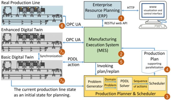
Figure 3.
Proposed architecture of the automation system conforming Industry 4.0 design principles and filling the gap between Industry 4.0 components on the shop-floor level and the traditional ERP system level, managing production/customers’ orders. The numbered circles denote a basic operation workflow of the system in terms of the invocation order.
In more details, Figure 3 also depicts an operation workflow, see the numbers in red circles assigned to individual system parts and tools. Production orders are managed by the ERP system, labeled as “1” in Figure 3. When the MES system (labeled as “2”) together with the real production line are ready, the MES system queries the ERP system for prioritized orders, selects the next one and invokes planning of the production process. In the step “3”, the Problem Generator as an entry part of the Production Planner and Scheduler specifies the PDDL problem. It means that it queries the latest state of the production system from the digital twin and it stores it as an initial state of the PDDL problem specification. This information is merged with the production order that is represented/transformed as a needed goal of the PDDL problem specification. Such a new PDDL problem specification is utilized by the PDDL solver, in our case Fast Downward. The domain specification, which specifies feasible actions and which is also necessary for production planning, is shared unchanged across various production lots. An output of the PDDL solver is a plan in a form of a sequence of actions. This sequence of actions is processed by the scheduler that parallelizes those actions/operations that can be executed in parallel. The result of such a complex step “3” of the operation workflow is a production plan (labeled as “4”) in a form of a directed acyclic graph that is executable in the MES system. In the step “5”, the MES system loads the production plan and orchestrates the production process by executing the operation per operation from the obtained production plan. In the real production line, production operations are invoked via OPC UA (see circled “6” in Figure 3). The same production operations are sent to the digital twin and here are two possibilities of the invocation. If the enhanced digital twin is used, the communication between the MES system and the enhanced digital twin is the very same as with the real production line, realized by OPC UA (see element “7A” in Figure 3). If just the basic digital twin is used, then the communication with it is done by sending PDDL actions (corresponding to current production operations) directly. An important benefit of this architecture is the flexibility and reactivity in terms that the production plans/recipes are no longer hard-coded in the shop-floor devices nor digital twins, but they are inferred in the production planner and scheduler on-the-fly under the current circumstances, enabling the re-planning of the production when needed.
Levels of maturity of the technical solution conforming the proposed approach are depicted in Figure 4. The first level is the formal description based on the PDDL notation. The second level is a digital twin, that is an encapsulated version of the formal description that is capable to be run in the continuous mode. The third level is the enhanced digital twin, which behaves as a synchronized simulation model. The enhanced digital twin is equipped with more detailed operation parameters, describing behavioral parameters of production operations. In the Industry 4.0 Testbed use-case, these operation parameters are mainly focused on operation time-durations. They can also include energy and power characteristics related to all types of operations, or other domain-specific parameters relevant for the engineering project.
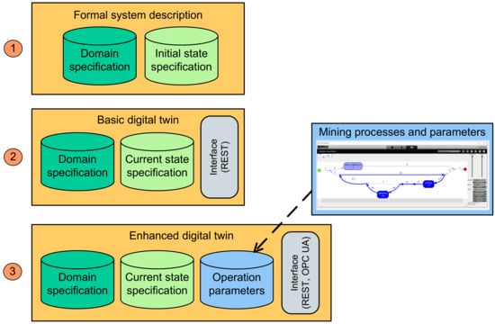
Figure 4.
Levels of formalization and maturity of digital twin artifacts. The enhanced digital twin on the third level differs from the basic digital twin on the second level with (i) the interface of the twin and (ii) operation parameters, whose values are mined out of event logs from system operation with process mining methods. The detailed view on the process mining model depicted on the right side is depicted later on in Figure 5.
The shift from the basic digital twin towards the enhanced digital twin applicable as a simulation model for the real production system is discussed in the subsequent subsection.
3.3. Assignment of Durations to Production Operations to Get More Realistic Digital Twins Applicable as Simulations
To enable more realistic simulations by means of the digital twin, it is necessary to assign approximate durations into the digital twin for all available operations.
There are two possible approaches to how to assign durations to production operation in order to transform the digital twin to provide simulation capabilities. The first approach is a bottom-up approach. The corner-stones of this approach are simplified models of atomic components, frequently called surrogate models [58] for individual components. An example of this bottom-up approach is the method AML2SIM, which is intended for assembling simulation models from atomic components [59] in the object-oriented manner within the signal-oriented environment of MATLAB-Simulink.
Another possibility is a top-down approach. We propose to utilize process mining to make the operation duration analysis. Process mining is a set of data science techniques for reconstructing operational processes from event logs. Process mining has been successfully used in various domains, such as medical. In the proposed approach, we recommend to capture performed production operations into logs of events, corresponding to these operations. Having timestamps assigned to the events, it is quite easy to reconstruct durations of individual actions. This calculation can be done either automatically, but then we most likely get time constants representing average durations of specific operations. Or we can mine more precise approximation of the expected durations according to various factors (that are usually modeled using probabilistic finite-state machines or dependency graphs), but then typically a basic human guidance is needed, and thus in case of more complicated dependencies the process is only semi-automatic (and not fully automatic).
Traditional (i.e., non-industrial) AI is focused on statistically significant observations (based on a high number of positive and negative samples). It is useful to find typical behavioral patterns and scenarios. On the contrary to the traditional AI, a so-called “industrial AI” (frequently related to industrial production systems and production processes) is more focused on identification of anomaly and rare events (e.g., deviations from typical production processes, unexpected/untested conditions, coincidences of signals, etc.). Contrary to the traditional AI, which is typically focused on the most probable/frequent patterns, industrial AI is focused on rare events or even events/conditions that have not occurred yet and that have to be identified early. One of the applications of industrial AI is zero-defect manufacturing [60,61], preventing/identifying failures and defects at a very early production stage, trying not to produce defected products. The process mining approach can be utilized for both types of AI, for the traditional one and for the industrial one. In the context of this article, we are focused on the traditional AI that is focused on statistically significant cases. Process mining is used to identify the typical time characteristics of production processes, especially typical time-durations of production operations corresponding to PDDL actions.
In a case where the event/operation logs do not include identifiers of discretized production operations, then the operations have to be recognized in time-series data. This procedure can differ according to a variety of communication patterns and communication protocols. The most frequent Industry 4.0 communication protocol OPC UA has quite complex information and address model, but the triggers for starting and ending production operations are typically straightforward.
Several data formats for representing event logs exist. We have achieved good results with the “IEEE Standard for eXtensible Event Stream”, frequently abbreviated as “XES” (XES format is standardized as IEEE 1849–2016 and it is available online: http://www.xes-standard.org/ (accessed on 14 February 2022). This standard supports interoperability of event logs and event streams that can be utilized/imported by diverse process mining tools and algorithms. In the frame of the proposed approach, we utilized a tool called ProM (i.e., Process Mining Framework, cf. http://www.promtools.org/doku.php (accessed on 14 February 2022)). An example of the result of process mining in the tool ProM is depicted in Figure 5. This example shows a sequence of operations pickup, putdown and shuttle move, captured in a single log trace.
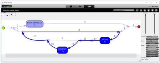
Figure 5.
An example of a result of process mining in the tool ProM. The source event log/data was acquired in the Industry 4.0 Testbed use-case and serialized into the standard format XES.
The process graph that has been depicted in Figure 5 (which is the same as the small diagram in Figure 4) is an example of a mined process from the operation of the Industry 4.0 Testbed use-case. It includes three types of operations (represented as boxes in the figure), which are several times repeated (denoted by numbers assigned to arrows). All of the operations have their start-time and end-time in the system event logs. The time-durations for all instances of operations are calculated as time differences between the corresponding end-time and start-time of the operation. These values are aggregated for each operation type. For example, there are three operation types in the Industry 4.0 Testbed use-case, namely pickup, putdown and shuttle move. We get a set of duration time values for each operation type and for each run of the production process. All available values are aggregated from all logs and operation instances by calculating mean values or medians, and standard deviations. The standard deviations are relevant for identification of outliers in the data/logs and operation defects/delays, which can be further utilized for example for predictive maintenance.
When setting up constants or dependencies as results of the process mining, it is useful to mitigate impact of outliers (e.g., longer operation duration) and to considered trends (useful for predictive maintenance [62], changes in production recipes, etc.).
In large-scale industrial problems, it is in theory possible to combine both bottom-up (i.e., holistic assembling of simulations) and top-down approaches (e.g., process mining).
4. Implementation, Evaluation and Discussion
The proposed approach was motivated by the Industry 4.0 Testbed use-case. It is an industrial-grade system for research and innovation, hosted at the Czech Technical University (CTU) in Prague, Czech Institute for Informatics, Robotics and Cybernetics—CIIRC (cf. https://www.ciirc.cvut.cz/ (accessed on 14 February 2022)). The ultimate goal of the Industry 4.0 Testbed is bridging the gap between scientific research using novel approaches (e.g., artificial intelligence, machine learning, planning and scheduling), and industrial practice with solid-founded techniques (e.g., ladder-logic-based control algorithms suitable for large production lots). Among other research topic, one of the most fundamental task is to find robust ways for supporting production flexibility and a high level of automation in highly robotized production systems. Examples of achievements include digital-twin-based production planning [63], reactive production planning [64], or an automated non-tactile method for robot calibration and control.
The core part of the production line of the Industry 4.0 Testbed is illustrated in Figure 6. The line is generic and capable to perform various types of production processes. The system is mainly designed for final assembling of products, that is, sequences of pick and place operations, realized by robots as manipulators, as well as transport system shuttles, moving around materials and products.
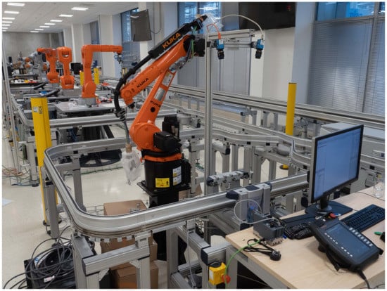
Figure 6.
Main part of the Industry 4.0 Testbed hosted at CTU in Prague—CIIRC.
The current layout (depicted in Figure 7) of our Testbed includes three traditional industrial robots KUKA Agilus (, , and ) and one cooperative robot KUKA iiwa (). Transport of goods among these robotic workstations is done by a mono-rail transportation system (Montrac), which consists of tracks assembled from straight segments, curves, and switches. Production material is transported by several shuttles that move on these tracks among so-called positioning units (, , , , and ), responsible for precise, repeatable, and firm stopping and positioning of shuttles in exactly mechanically-specified locations. In addition, this system can be easily integrated with other systems within the Industry 4.0 Testbed via automated guided vehicles (AGVs), more specifically, by autonomous mobile robot (AMR) KUKA KMR.
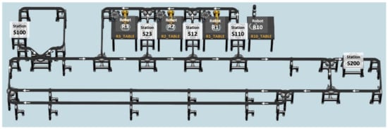
Figure 7.
Topology of the Industry 4.0 Testbed production line. It is equipped with 4 KUKA robots, a transportation system Montrac with 5 work-stations and 6 shuttles moving around the Montrac mono-rail (shuttles are not depicted on the figure). Stations , , and are reachable by corresponding robots from both sides.
The Industry 4.0 Testbed is orchestrated by our prototypical implementation of MES having integrated the planner & scheduler as it was described in the previous section. Domains and problems are specified in PDDL in LISP syntax (cf. https://lisp-lang.org/ (accessed on 14 February 2022)), similarly as resulting production plans. These production plans are interpreted by MES at runtime by translating planned actions to and from the OPC UA protocol that is used for communication with all of the shop-floor devices. In both cases, the dynamically computed production process obtained by the AI planner usually comprises a sequence of production operations, similar to the following:
- •
- Picking material from given coordinates (by a robot);
- •
- Placing material to given coordinates (by a robot);
- •
- Moving material (by a shuttle);
- •
- Picking material from a shuttle (by another robot); and
- •
- Placing it in order to achieve assembly progress towards a finished good.
The Industry 4.0 Testbed is capable to perform various production scenarios/domains, which are especially focused on product assembling (currently, there are no available tools for, for example, drilling or welding). Among other assembling domains, the Testbed is capable to assemble small 3-D printed trucks, consisting of a chassis, a cabin (of one of the four available colors) and a body (a scraper, an open-top, a tank, and stake-bed of four colors). Each production order originates in the ERP system and each order queried from the ERP system is executed by the MES system. The MES system calls the planner and scheduler according to the diagram in Figure 3 and afterwards executes the obtained on-the-fly planned production process. Both the planning and execution is done with the tight integration of the digital twin, providing the global updated state of the real production system and required products.
In more details, one of the automatically generated production plans for assembling one truck model (depending on the latest state of the production line and ordered truck) is as an example depicted in Figure 8. This particular plan consists of 5 tasks (i.e., tasks 1–5), realizing production operations. Each production task is assigned to a specific resource, denoted by “location” (such as the robot or the transportation system Montrac). The action of the task specifies the production operation, including its parameters (such as robotic_pick operation parameterized with formal names of source locations and source coordinates and a rotation R of the gripper, and manipulated component like white cabin). Among production tasks are arrows denoting dependencies, specifying in which order the production operations can be executed.
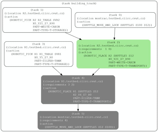
Figure 8.
An exemplary executed plan of the production in Industry 4.0 Testbed in the form of a dependency graph that was produced automatically by Production Planner & Scheduler. Our MES is currently executing this plan where white color represents already finished tasks, green color represents currently processed tasks, and grey color represents still pending tasks.
The production plan is a graph resulting from parallelization of the sequential plan (resulting from the AI planning with PDDL) by the scheduler (parallelization of the sequential plan is done by analysis of shared/blocking resources inside each action used in a specific sequential plan). In other words, the example of the production plan depicted in Figure 8 is a result of planning based on PDDL and parallelization by the scheduler into the form of a dependency directed acyclic graph. The MES system subsequently executes this plan with the real machinery, communicating with it via OPC UA.
During the design and implementation of the prototype, we followed the method steps proposed in the previous section. In the first method step, we formalized the domain description of the Testbed production line in terms of types of resources and their connections (i.e., specified physical and logic topology of the system). We defined products and their structure. In the second method step, we defined available/feasible production operations and assigned them to production resources. The result of these two steps is depicted on the left-hand side of Figure 2, which is the specification of the domain for Montrac. In addition, we defined a robotic domain, defining production operation pick and place (it exceeds the size of the figure and the detailed domain description is not the core part of this contribution). You can see in the Montrac domain specification definitions of utilized predicates and the action/operation Shuttle_move_and_lock that formalizes preconditions and effects of shuttle movement operations. In the third method step, we specified the initial state of the entire system, see the right-hand side specification in Figure 2. It is the very initial state, and not the traditional “home state”, as the production line is not required to return to such an initial or home state after finishing each production (because the digital twin continuously keeps the latest state of the production line that is consequently reused for further production planning). We skipped the fourth method step, because we do not currently have any advanced vision/pattern recognition systems attached. Last but not least, we finished the design process with creating the technical configuration file in AutomationML in the fifth method step, specifying URLs for all relevant endpoints and specified mappings between PDDL actions and respective OPC UA information models. Based on these created specifications, the tool set depicted in Figure 3 is configured and started and it is capable to continuously plan and execute/produce orders coming from the ERP system.
In this Industry 4.0 Testbed research and testing environment/setup, we tested and validated the proposed approach in practice. We tested on numerous cases and real production runs that one can easily add and remove/disable production resources to the system by just simple modifications of the problem specification. One can also easily add and remove (or temporarily disable) products that can be produced on the production system. Together with the dynamically planned production recipes/plans, we gained the full flexibility in terms of the product-process-resource notation. It means that we fulfilled flexibility requirements of Industry 4.0 vision (which are however not the only requirements for having Industry 4.0 system for sure). On the other hand, we realized that creation of the formal specification of the system behavior with PDDL formalization can be quite tricky and complicated for industrial practitioners. Therefore, we would like to specify recommendations how to specify required knowledge in a data format that is better recognized in industry (such as AutomationML) and to introduce ways for semi-automated generation of PDDL formal specifications with the use of this data format in future work.
Overall, we found the proposed approach to be flexible and efficient for production in small lots (for which the traditional approaches are not feasible). Based on the set of experiments performed in the Industry 4.0 Testbed, we proved that this approach can significantly contribute to the higher flexibility and production efficiency in industrial facilities.
4.1. Measured Results
We have conducted long-term testing of the proposed solution in the Industry 4.0 Testbed facility for a time period of more than one year, including more than 1000 continuous production processes. All these performed production processes were logged into the standardized XES format.
We analyzed the performed production processes captured in the XES event logs. The overall production durations are depicted in a histogram in Figure 9. It shows that typical production processes take approximately 2–3 min (cf. 120–180 s in Figure 9). The histogram also depicts approximately 50 performed production processes, which took very short time (and they seem to be outliers of the normal-like distribution in the histogram). This is not an error, but it represents two situations: (i) we order a product that had been already produced and was just available, therefore, no production process was needed at all. Second, (ii) Production ended up with an error and ordered product could not be produced without restarting the production process. On the opposite side of the histogram (cf. right-hand side of Figure 9) is an outlier, representing a production process that took more than 500 s. This was caused by a delayed Montrac shuttle that got stuck on a Montrac switch.
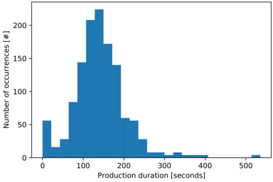
Figure 9.
Histogram of production process lengths.
The time needed for querying a particular production order from the ERP system, grabbing the global state of the production system from the digital twin, calculating a production plan and schedule by the AI planner and scheduler up to beginning the physical production process via MES does not exceed 10 s. As part of this time period, the AI planning process utilizing the global system state represented in the digital twin itself needed less than 8 s.
Production processes planned to produce the ordered products included in the most of the cases four production operations, as it is depicted in a histogram in Figure 10. Nevertheless, the longest production plans (in terms of operation count, not from the need production time point of view) needed 28 operations.
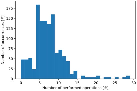
Figure 10.
Histogram of a number of performed production operations (corresponding to PDDL actions) during each production process, planned for production of one product order (i.e., one truck model).
For all the testing, tuning and experiments in the Industry 4.0 Testbed, we utilized one computation node of the self-hosted high performance computing cluster, which is orchestrated by Intel® Xeon® (Intel and the Intel logo are trademarks of Intel Corporation or its subsidiaries, Santa Clara, USA) CPU E5-2630 v2 @ 2.6 GHz, 4 cores, 16 GB RAM, 100 GB SSD storage, and Ubuntu Linux 18.04.2 LTS.
As a result of the performed sets of experiments, we concluded that the proposed solution offers satisfactory reliability and performance for continuous operation of the system size corresponding to the Industry 4.0 Testbed. We have not faced any problems related to the digital twin, production planning system, nor MES. On the contrary, we had to fix hardware related issues related to industrial-grade hardware devices several times. Namely we had to fix issues with industrial robots and robotic grippers. An important benefit of the proposed approach is the possibility to easily break and resume/re-plan the production process utilizing only those production resources, that are not broken. For sure, with limited set of resources, the needed production time per each product is typically higher. On the other hand, it is much better to operate the production line in a sub-optimal/slower mode (with the proposed solution), than to entirely stop the production of all products and have the line in standstill until the system is completely repaired, as is typical in current industrial production systems.
4.2. Lessons-Learned during System Ramp-Up
During the ramp-up process of the proposed approach for the Industry 4.0 Testbed, we encountered numerous problems/issues and unexpected points as well as some positive surprises.
On the one hand, one of the positive surprises was that the AI planning algorithm frequently found a solution even for cases where its existence was unexpected by humans. When testing, some plans were surprisingly significantly more efficient than those proposed by humans, especially in terms of number of production operations needed to be performed as well as length of the production plan execution (which is frequently the effect of lower number of operations).
On the other hand, an encountered issue was a low absolute accuracy of industrial robots together with a needed proper calibration of their coordinate systems (namely local coordinate systems of the tool center point of the gripper/end-effector mounted to the robot flange, as well as the base frames, that is, the local coordinate systems of shuttles/positioning units and warehouse positions). Although robot accuracy and calibration are typical issues known from industrial robotics, in the proposed planner-centric approach, robot trajectories and working points are not taught manually and thus cannot be manually fine-tuned, as it is frequently done in traditional hard-coded robot codes and fixed production recipes. As a result of the encountered calibration issue, we have started a new research thread focused on automated robot calibration with the use of a laser tracking system.
At the first versions of the Industry 4.0 Testbed solution, we were not using any digital twin at system runtime. This first solution was however not efficient, because it required restarting of the whole system to the initial state (requiring some manual interventions/manipulation with material and semi-products as well) in any case of hardware or software errors (a discalibrated/broken gripper of a robot, a collision of a robot, a bad content on a shuttle, unresponsive Montrac system, etc.). The frequent need for restarting of almost everything was a crucial motivation to incorporate the digital twin as the integral part of the automation/control system loop and to utilize it continuously at runtime. Since the digital twin keeps the latest state of the entire production system, it brings the opportunity to simply re-plan the production from the last safe state when some error occurs without the need for restarting the entire production line. In some cases, it can require to disable some specific resource (such as, due to broken gripper fingers, of a specific robot), but despite the limited system setup, it allows us to continue with the production. In numerous cases, it enables to continue even in unlimited mode.
Another benefit coming from the digital twin utilization is a possibility to decrease a number of sensors or cameras, because numerous pieces of information do not need to be measured directly, but the information is memorized and kept in the digital twin (e.g., which component is located on a specific warehouse position or whether this position is free). Such a reduction of directly measured process variables is important not only from the cost of investment required to buy those pieces of machinery, but also from the regular maintenance point of view, because each hardware part of the industrial system has to be regularly checked, calibrated, tested, and replaced if it is broken. All these maintenance steps introduce delays and outages of the production, which can be prevented by using soft-sensors as parts of the digital twins.
We have also tried to integrate and utilize industrial-graded solutions (namely by Siemens), but the status quo (during the years 2020 and 2021) did not allow us to replicate the full research-prototype functionality with industry-oriented tools. We have started the process of comparing the proposed approach with other research-oriented approaches, especially multi-agent ones, however, it requires further significant effort and development time and resources, meaning that we have not found any off-the-shelf solution that could be easily applied for comparison with the proposed approach.
Despite local technical issues, we overall found the proposed approach very efficient compared to the “classical” approach. For comparison, we tried to implement a PLC-based control system in the early stage of the Industry 4.0 Testbed production line development. Even if we tried to implement it for a reduced number of components (2 robots and 3 workstations of Montrac) controlled by PLCs (Siemens 1518 and Siemens 1512), programming, testing, and debugging became nearly not feasible (due to high program complexity and heterogeneity, delays due to recompilation/redeployment of the project, as well as inability of repeatability/reproducibility of runtime errors). Based on our experience, shifting towards more dynamic environments, utilizing the aforementioned methodology (digital twin, AI planning and scheduling, interpretation of dynamically created production plans, etc.), is a very promising way to tackle increasing complexity and higher demanding requirements of industrial production systems.
5. Conclusions and Future Work
Conditions in the global market together with advances in Industry 4.0 and smart manufacturing technologies bring strict requirements on flexibility and a higher degree of versatility of industrial production systems. Ability to be able to react on quickly and heavily changing market conditions are one of the most important requirements to be satisfied in production system engineering.
This article proposes a production system design paradigm that is significantly focused on a formal description of system components/resources and their supported operations/skills. The term digital twin is in this context understood as an executable/simulable tool implementing this formal system description. The proposed digital-twin-centric approach supports flexible production planning and re-planning.
Simulation modeling is, in the proposed context, understood as an assignment of time constants to the formal digital twin. Such an assignment can be done traditionally in the bottom-up manner, starting at device datasheets and domain-specific emulations and simulations. Or the time constants or time dependencies can be inferred from running systems or their components by means of process mining methods. In this case, values of production operation duration are inferred from event/operation logs of running systems logged by a new generation of MES systems capable to perform such detailed event logging.
This article thus presents an innovative approach for automation and control of Industry 4.0 production systems. The digital twin, as the fundamental corner-stone of the proposed solution, keeps the up-to-date global state of the entire production system. Due to the tight integration of the digital twin and the automated AI planning, the solution offers the high degree of flexibility. The proposed integration approach contributes to more effective, efficient, flexible, and goal-oriented manufacturing execution processes.
The proposed solution was successfully validated with the use of the Industry 4.0 Testbed. The long-term testing and demonstrating of this system to researchers and practitioners as well as to wide public audience together with detailed logging of the system operation to the XES format, which was subsequently processed and checked by process mining tools, proved that this approach is suitable for long-term robust operation. The approach brings not only the required flexibility in products and production resources, but it also significantly strengthens reliability and resilience of the entire production system, because if some resource is broken, then the production processes can be easily re-planned to the remaining production resources.
Future Work
In future work, we would like to deploy this solution into a real factory and test it under large-scale conditions. We have already explained that in large-scale industrial problems, it is theoretically possible to combine both bottom-up and top-down approaches for converting digital twins into more detailed synchronized simulation models, however, we have not utilized this combination in practice yet. Therefore, we would like to investigate the possibilities for obtaining simulation parameter values in more details, including combination of available domain-specific specifications or specialized simulations, together with inferred values at runtime with process mining methods.
We would also like to investigate an “online supervision” with the digital twin. Since all of the components have to be synchronized with the digital twin, the online supervision (an overview of the global state, an opportunity to allow or block selected operation) can be performed over the digital twin instead of multiple components with their specific interfaces.
Last but not least, an automated error recovery on top of the planning system combined with the digital twin is a topic that we have already opened but we would like to finish it in future work. When some component is broken down, then some special case needs to be activated in the contemporary industrial systems. Due to digital twin and AI planning, the broken component can be easily disabled inside the digital twin global state and then the production goal can be recomputed. If a solution exists, then the production line can continue with a new found plan. Otherwise, the broken component is the so-called key component and maintenance/service needs to be made as soon as possible.
Author Contributions
P.N. and J.V. contributed to the main idea and to the conceptualization. Software prototypes were implemented by P.N. and J.V. Validation and testing was done by P.N. and J.V. The structure of the manuscript was defined by P.N. The entire manuscript was written by P.N. and J.V. and it was proof-read by P.N. All authors have read and agreed to the published version of the manuscript.
Funding
This work was funded by the Ministry of Education, Youth and Sport of the Czech Republic within the project Cluster 4.0 (No. CZ.02.1.01/0.0/0.0/16_026/0008432) and the RICAIP project that has received funding from the European Union’s Horizon 2020 research and innovation programme under grant agreement No. 857306. This article has been also supported by the Flexible AC/DC microgrid for collective housing project (No. TK02020005) funded by the Technology Agency of the Czech Republic.
Institutional Review Board Statement
Not applicable.
Informed Consent Statement
Not applicable.
Data Availability Statement
Examples of data from this study can be made available upon request.
Conflicts of Interest
The authors declare no conflict of interest.
References
- Vogel-Heuser, B. Herausforderungen und Anforderungen aus Sicht der IT und der Automatisierungstechnik. In Handbuch Industrie 4.0 Bd.4: Allgemeine Grundlagen; Vogel-Heuser, B., Bauernhansl, T., ten Hompel, M., Eds.; Springer: Berlin/Heidelberg, Germany, 2017; pp. 33–44. [Google Scholar] [CrossRef]
- Lüder, A.; Schleipen, M.; Schmidt, N.; Pfrommer, J.; Henßen, R. One step towards an industry 4.0 component. In Proceedings of the 2017 13th IEEE Conference on Automation Science and Engineering (CASE), Xi’an, China, 20–23 August 2017; pp. 1268–1273. [Google Scholar] [CrossRef]
- Wooldridge, M.; Jennings, N.R. Intelligent agents: Theory and practice. Knowl. Eng. Rev. 1995, 10, 115–152. [Google Scholar] [CrossRef] [Green Version]
- Ghazal, R.; Malik, A.; Raza, B.; Qadeer, N.; Qamar, N.; Bhatia, S. Agent-Based Semantic Role Mining for Intelligent Access Control in Multi-Domain Collaborative Applications of Smart Cities. Sensors 2021, 21, 4253. [Google Scholar] [CrossRef] [PubMed]
- Singh, M.; Fuenmayor, E.; Hinchy, E.P.; Qiao, Y.; Murray, N.; Devine, D. Digital Twin: Origin to Future. Appl. Syst. Innov. 2021, 4, 36. [Google Scholar] [CrossRef]
- Kritzinger, W.; Karner, M.; Traar, G.; Henjes, J.; Sihn, W. Digital Twin in manufacturing: A categorical literature review and classification. IFAC-PapersOnLine 2018, 51, 1016–1022. [Google Scholar] [CrossRef]
- Dong, B.; Wally, B.; Ferscha, A. Tokenized Interaction Architecture. In Proceedings of the 2nd International Workshop on Pervasive Advertising, Lübeck, Germany, 28 September–2 October 2009. [Google Scholar]
- Kassen, S.; Tammen, H.; Zarte, M.; Pechmann, A. Concept and Case Study for a Generic Simulation as a Digital Shadow to Be Used for Production Optimisation. Processes 2021, 9, 1362. [Google Scholar] [CrossRef]
- Bartodziej, C.J. The concept Industry 4.0. In The Concept Industry 4.0: An Empirical Analysis of Technologies and Applications in Production Logistics; Springer Fachmedien Wiesbaden: Wiesbaden, Germany, 2017; pp. 27–50. [Google Scholar] [CrossRef]
- Etz, D.; Frühwirth, T.; Kastner, W. Flexible Safety Systems for Smart Manufacturing. In Proceedings of the 25th IEEE International Conference on Emerging Technologies and Factory Automation (ETFA 2020), Vienna, Austria, 8–11 September 2020; Volume 1, pp. 1123–1126. [Google Scholar] [CrossRef]
- Tao, F.; Qi, Q.; Liu, A.; Kusiak, A. Data-driven smart manufacturing. J. Manuf. Syst. 2018, 48, 157–169. [Google Scholar] [CrossRef]
- Sufian, A.T.; Abdullah, B.M.; Ateeq, M.; Wah, R.; Clements, D. A Roadmap Towards the Smart Factory. In Proceedings of the 2019 12th International Conference on Developments in eSystems Engineering (DeSE), Kazan, Russia, 7–10 October 2019; pp. 978–983. [Google Scholar] [CrossRef]
- Lu, Y.; Xu, X.; Wang, L. Smart manufacturing process and system automation – A critical review of the standards and envisioned scenarios. J. Manuf. Syst. 2020, 56, 312–325. [Google Scholar] [CrossRef]
- Cavanillas, J.M.; Curry, E.; Wahlster, W. The Big Data Value Opportunity. In New Horizons for a Data-Driven Economy—A Roadmap for Usage and Exploitation of Big Data in Europe; Cavanillas, J.M., Curry, E., Wahlster, W., Eds.; Springer: Berlin/Heidelberg, Germany, 2016; pp. 3–11. [Google Scholar] [CrossRef] [Green Version]
- Hänel, A.; Seidel, A.; Frieß, U.; Teicher, U.; Wiemer, H.; Wang, D.; Wenkler, E.; Penter, L.; Hellmich, A.; Ihlenfeldt, S. Digital Twins for High-Tech Machining Applications—A Model-Based Analytics-Ready Approach. J. Manuf. Mater. Process. 2021, 5, 80. [Google Scholar] [CrossRef]
- Hänel, A.; Schnellhardt, T.; Wenkler, E.; Nestler, A.; Brosius, A.; Corinth, C.; Fay, A.; Ihlenfeldt, S. The development of a digital twin for machining processes for the application in aerospace industry. Procedia CIRP 2020, 93, 1399–1404. [Google Scholar] [CrossRef]
- Sierla, S.; Azangoo, M.; Fay, A.; Vyatkin, V.; Papakonstantinou, N. Integrating 2D and 3D Digital Plant Information Towards Automatic Generation of Digital Twins. In Proceedings of the 2020 IEEE 29th International Symposium on Industrial Electronics (ISIE), Delft, The Netherlands, 17–19 June 2020; pp. 460–467. [Google Scholar] [CrossRef]
- Sierla, S.; Azangoo, M.; Rainio, K.; Papakonstantinou, N.; Fay, A.; Honkamaa, P.; Vyatkin, V. Roadmap to semi-automatic generation of digital twins for brownfield process plants. J. Ind. Inf. Integr. 2021, 100282. [Google Scholar] [CrossRef]
- Braun, D.; Ashtari, B.; Weyrich, M. 29 Integration of data and software into the Digital Twin via AML. In AutomationML: The Industrial Cookbook; Drath, R., Ed.; De Gruyter Oldenbourg: Berlin, Germany, 2021; pp. 521–538. [Google Scholar] [CrossRef]
- Vogel-Heuser, B.; Ocker, F.; Scheuer, T. An approach for leveraging Digital Twins in agent-based production systems. Automatisierungstechnik 2021, 69, 1026–1039. [Google Scholar] [CrossRef]
- Kadera, P.; Novák, P. Performance Modeling Extension of Directory Facilitator for Enhancing Communication in FIPA-Compliant Multiagent Systems. IEEE Trans. Ind. Inform. 2017, 13, 688–695. [Google Scholar] [CrossRef]
- Reiche, L.T.; Gundlach, C.S.; Mewes, G.F.; Fay, A. The Digital Twin of a System: A Structure for Networks of Digital Twins. In Proceedings of the 2021 26th IEEE International Conference on Emerging Technologies and Factory Automation (ETFA ), Vasteras, Sweden, 7–10 September 2021. [Google Scholar] [CrossRef]
- Steindl, G.; Kastner, W. Semantic Microservice Framework for Digital Twins. Appl. Sci. 2021, 11, 5633. [Google Scholar] [CrossRef]
- Wang, Y.; Wang, X.; Liu, A. Digital Twin-driven Supply Chain Planning. Procedia CIRP 2020, 93, 198–203. [Google Scholar] [CrossRef]
- Zheng, X.; Lu, J.; Kiritsis, D. The emergence of cognitive digital twin: Vision, challenges and opportunities. Int. J. Prod. Res. 2021, 1–23. [Google Scholar] [CrossRef]
- Rožanec, J.M.; Lu, J.; Rupnik, J.; Škrjanc, M.; Mladenić, D.; Fortuna, B.; Zheng, X.; Kiritsis, D. Actionable cognitive twins for decision making in manufacturing. Int. J. Prod. Res. 2021, 1–27. [Google Scholar] [CrossRef]
- Jones, D.; Snider, C.; Nassehi, A.; Yon, J.; Hicks, B. Characterising the Digital Twin: A systematic literature review. CIRP J. Manuf. Sci. Technol. 2020, 29, 36–52. [Google Scholar] [CrossRef]
- Ghallab, M.; Nau, D.S.; Traverso, P. Automated Planning and Acting; Cambridge University Press: Cambridge, UK, 2016. [Google Scholar]
- VDI. Formalised Process Descriptions Information Model, VDI/VDE 3682; Verein Deutscher Ingenieure (VDI): Duesseldorf, Germany, 2015. [Google Scholar]
- Caesar, B.; Hänel, A.; Wenkler, E.; Corinth, C.; Ihlenfeldt, S.; Fay, A. Information Model of a Digital Process Twin for Machining Processes. In Proceedings of the 25th IEEE International Conference on Emerging Technologies and Factory Automation, ETFA 2020, Vienna, Austria, 8–11 September 2020; IEEE: Piscataway, NJ, USA, 2020; pp. 1765–1772. [Google Scholar] [CrossRef]
- Hart, P.E.; Nilsson, N.J.; Raphael, B. A Formal Basis for the Heuristic Determination of Minimum Cost Paths. IEEE Trans. Syst. Sci. Cybern. 1968, 4, 100–107. [Google Scholar] [CrossRef]
- Fikes, R.; Nilsson, N.J. STRIPS: A New Approach to the Application of Theorem Proving to Problem Solving. In Proceedings of the 2nd International Joint Conference on Artificial Intelligence, London, UK, 1–3 September 1971; Cooper, D.C., Ed.; William Kaufmann: Burlington, MA, USA, 1971; pp. 608–620. [Google Scholar]
- Silva, J.P.M.; Sakallah, K.A. GRASP: A Search Algorithm for Propositional Satisfiability. IEEE Trans. Comput. 1999, 48, 506–521. [Google Scholar] [CrossRef] [Green Version]
- Eén, N.; Sörensson, N. An Extensible SAT-solver. Theory and Applications of Satisfiability Testing. In Lecture Notes in Computer Science, Proceedings of the 6th International Conference, SAT 2003, Santa Margherita Ligure, Italy, 5–8 May 2003; Selected Revised Papers; Giunchiglia, E., Tacchella, A., Eds.; Springer: Berlin/Heidelberg, Germany, 2003; Volume 2919, pp. 502–518. [Google Scholar] [CrossRef]
- Audemard, G.; Simon, L. On the Glucose SAT Solver. Int. J. Artif. Intell. Tools 2018, 27, 1840001:1–1840001:25. [Google Scholar] [CrossRef]
- Helmert, M. The Fast Downward Planning System. J. Artif. Intell. Res. 2006, 26, 191–246. [Google Scholar] [CrossRef]
- Richter, S.; Westphal, M. The LAMA Planner: Guiding Cost-Based Anytime Planning with Landmarks. J. Artif. Intell. Res. 2010, 39, 127–177. [Google Scholar] [CrossRef] [Green Version]
- Wally, B.; Vyskočil, J.; Novák, P.; Huemer, C.; Šindelář, R.; Kadera, P.; Mazak, A.; Wimmer, M. Flexible Production Systems: Automated Generation of Operations Plans Based on ISA-95 and PDDL. IEEE Robot. Autom. Lett. 2019, 4, 4062–4069. [Google Scholar] [CrossRef] [Green Version]
- Sousa, A.R.; Tavares, J.J.P.Z.S. Toward Automated Planning Algorithms Applied to Production and Logistics. IFAC Proc. Vol. 2013, 46, 165–170. [Google Scholar] [CrossRef]
- Kovacs, D.L. Complete BNF Description of PDDL 3.1; Language Specification, Department of Measurement and Information Systems, Budapest University of Technology and Economics: Budapest, Hungary, 2011. [Google Scholar]
- Vogel-Heuser, B.; Fay, A.; Schaefer, I.; Tichy, M. Evolution of software in automated production systems: Challenges and research directions. J. Syst. Softw. 2015, 110, 54–84. [Google Scholar] [CrossRef] [Green Version]
- Barth, M.; Fay, A. Automated generation of simulation models for control code tests. Control. Eng. Pract. 2013, 21, 218–230. [Google Scholar] [CrossRef]
- Rogalla, A.; Fay, A.; Niggemann, O. Improved Domain Modeling for Realistic Automated Planning and Scheduling in Discrete Manufacturing. In Proceedings of the 23rd IEEE International Conference on Emerging Technologies and Factory Automation (ETFA), Turin, Italy, 4–7 September 2018; pp. 464–471. [Google Scholar]
- Novák, P.; Vyskočil, J.; Kadera, P. Plan Executor MES: Manufacturing Execution System Combined with a Planner for Industry 4.0 Production Systems. In Proceedings of the 9th International Conference on Industrial Applications of Holonic and Multi-Agent Systems (HoloMAS), Linz, Austria, 26–29 August 2019; Mařík, V., Kadera, P., Rzevski, G., Zoitl, A., Anderst-Kotsis, G., Tjoa, A.M., Khalil, I., Eds.; Springer: Berlin/Heidelberg, Germany, 2019; pp. 67–80. [Google Scholar]
- Wally, B.; Vyskočil, J.; Novák, P.; Huemer, C.; Šindelář, R.; Kadera, P.; Mazak, A.; Wimmer, M. Production Planning with IEC 62264 and PDDL. In Proceedings of the 17th IEEE International Conference on Industrial Informatics (INDIN), Helsinki, Finland, 22–25 July 2019; pp. 492–499. [Google Scholar]
- Busert, T.; Fay, A. Information Quality Dimensions for Identifying and Handling Inaccuracy and Uncertainty in Production Planning and Control. In Proceedings of the 2018 IEEE 23rd International Conference on Emerging Technologies and Factory Automation (ETFA), Turin, Italy, 4–7 September 2018; Volume 1, pp. 581–588. [Google Scholar] [CrossRef]
- Talkhestani, B.A.; Weyrich, M. Digital Twin of manufacturing systems: A case study on increasing the efficiency of reconfiguration. Automatisierungstechnik 2020, 68, 435–444. [Google Scholar] [CrossRef]
- Kadera, P.; Jirkovský, V.; Mařík, V. Revival of MAS Technologies in Industry. Trans. Large Scale Data Knowl. Centered Syst. 2021, 48, 131–144. [Google Scholar] [CrossRef]
- Gehlhoff, F.; Wiegandt, L.; Fay, A. Agent-Based Decentralised Process Planning and Evolutionary Change Propagation. In Proceedings of the 2021 22nd IEEE International Conference on Industrial Technology (ICIT), Valencia, Spain, 10–12 March 2021; Volume 1, pp. 1015–1020. [Google Scholar] [CrossRef]
- Wagg, D.J.; Worden, K.; Barthorpe, R.J.; Gardner, P. Digital Twins: State-of-the-Art and Future Directions for Modeling and Simulation in Engineering Dynamics Applications. ASCE-ASME J. Risk Uncertain. Eng. Syst. Part B Mech. Eng. 2020, 6, 030901. [Google Scholar] [CrossRef]
- Grznár, P.; Krajčovič, M.; Gola, A.; Dulina, L.; Furmannová, B.; Mozol, v.; Plinta, D.; Burganová, N.; Danilczuk, W.; Svitek, R. The Use of a Genetic Algorithm for Sorting Warehouse Optimisation. Processes 2021, 9, 1197. [Google Scholar] [CrossRef]
- Wagner, C.; Grothoff, J.; Epple, U.; Drath, R.; Malakuti, S.; Grüner, S.; Hoffmeister, M.; Zimermann, P. The role of the Industry 4.0 asset administration shell and the digital twin during the life cycle of a plant. In Proceedings of the 22nd IEEE International Conference on Emerging Technologies and Factory Automation (ETFA 2017), Limassol, Cyprus, 12–15 September 2017; pp. 1–8. [Google Scholar] [CrossRef]
- Lüder, A.; Graf, A.; Müller, M.; Schleipen, M.; Wiegand, M.; Biffl, S.; Drath, R. 19 Serialization of the Asset Administration Shell by AutomationML. In AutomationML: The Industrial Cookbook; Drath, R., Ed.; De Gruyter Oldenbourg: Berlin, Germany, 2021; pp. 365–378. [Google Scholar] [CrossRef]
- Mahnke, W.; Leitner, S.H.; Damm, M. OPC Unified Architecture; Springer Science & Business Media: Berlin/Heidelberg, Germany, 2009. [Google Scholar]
- Novák, P.; Douda, P.; Vyskočil, J.; Wally, B. PyAML: Enhancing AutomationML for Advanced Virtualization of Industry 4.0 Cyber-Physical Production Systems with Python Code Injections. In Proceedings of the 26th IEEE International Conference on Emerging Technologies and Factory Automation, ETFA 2021, Västerås, Sweden, 7–10 September 2021; IEEE: Piscataway, NJ, USA, 2021. [Google Scholar]
- Van der Aalst, W.M.; Dustdar, S. Process Mining Put into Context. IEEE Internet Comput. 2012, 16, 82–86. [Google Scholar] [CrossRef]
- Van der Aalst, W. Data Science in Action. In Process Mining: Data Science in Action; Springer: Berlin/Heidelberg, Germany, 2016; pp. 3–23. [Google Scholar] [CrossRef]
- Bárkányi, A.; Chován, T.; Németh, S.; Abonyi, J. Modelling for Digital Twins—Potential Role of Surrogate Models. Processes 2021, 9, 476. [Google Scholar] [CrossRef]
- Novák, P.; Ekaputra, F.J.; Biffl, S. Generation of Simulation Models in MATLAB-Simulink Based on AutomationML Plant Description. IFAC-PapersOnLine 2017, 50, 7613–7620. [Google Scholar] [CrossRef]
- May, G.; Kiritsis, D. Zero Defect Manufacturing Strategies and Platform for Smart Factories of Industry 4.0. In Proceedings of the 4th International Conference on the Industry 4.0 Model for Advanced Manufacturing, Belgrade, Serbia, 3–6 June 2019; Monostori, L., Majstorovic, V.D., Hu, S.J., Djurdjanovic, D., Eds.; Springer International Publishing: Cham, Switzerland, 2019; pp. 142–152. [Google Scholar]
- Lindström, J.; Kyösti, P.; Birk, W.; Lejon, E. An Initial Model for Zero Defect Manufacturing. Appl. Sci. 2020, 10, 4570. [Google Scholar] [CrossRef]
- Cárcel-Carrasco, J.; Gómez-Gómez, C. Qualitative Analysis of the Perception of Company Managers in Knowledge Management in the Maintenance Activity in the Era of Industry 4.0. Processes 2021, 9, 121. [Google Scholar] [CrossRef]
- Novák, P.; Vyskočil, J.; Wally, B. The Digital Twin as a Core Component for Industry 4.0 Smart Production Planning. IFAC-PapersOnLine 2020, 53, 10803–10809. [Google Scholar] [CrossRef]
- Wally, B.; Vyskočil, J.; Novák, P.; Huemer, C.; Šindelář, R.; Kadera, P.; Mazak-Huemer, A.; Wimmer, M. Leveraging Iterative Plan Refinement for Reactive Smart Manufacturing Systems. IEEE Trans. Autom. Sci. Eng. 2021, 18, 230–243. [Google Scholar] [CrossRef]
Publisher’s Note: MDPI stays neutral with regard to jurisdictional claims in published maps and institutional affiliations. |
© 2022 by the authors. Licensee MDPI, Basel, Switzerland. This article is an open access article distributed under the terms and conditions of the Creative Commons Attribution (CC BY) license (https://creativecommons.org/licenses/by/4.0/).