Abstract
Air-doors are important facilities for regulating the air flow in a mine ventilation network. It is of value to study the influence of air-doors, which are adjacent to a fire source on smoke back-layering in order to build a rational ventilation system. By regulating air-doors in a mine ventilation network test platform, two typical mine ventilation networks, with parallel branches and a diagonal branch, were constructed. During the study, into the closing degree of the air-doors adjacent to a fire source in a ventilation network with parallel branches, the back-layering length is up to 3.70 m when the ventilation velocity is 1.40 m/s. When the air-door on the return side of the adjacent branch is closed, the back-layering subsides within 1 min and the upstream temperature drops rapidly to normal. When the air-door is half closed, there is still a back-layering flow within 5 min. Smoke control, with the air-door is closed, is better than when the air-door is half closed. Based on this, tests into the influence of the closing position of air-doors, which are adjacent to a fire source, were carried out in a ventilation network with a diagonal branch. Results indicate that when the ventilation velocity is 1.70 m/s, the back-layering flow spreads to the diagonal branch, and the air flow velocity of both the adjacent branch and the diagonal branch increases. When closing the air-door on the return side of the adjacent branch, the back-layering rapidly subsided. The wind velocity on the intake side of the adjacent branch is stabilized after a rapid decrease, and the wind velocity of the diagonal branch is stabilized after a rapid increase. When closing the air-door on the intake side of the adjacent branch, the smoke from the diagonal branch spreads. Compared with closing the intake side air-door, closing the air-door on the return side of the adjacent branch is more effective in preventing back-layering. This work provides a reference for preventing back-layering and guiding the evacuation of people from the upstream of a fire source.
1. Introduction
Mine fires are one of the main disasters that threatens the safety of coal production [1,2,3]. A large mass of toxic and hazardous gases, at high temperatures, are produced during the process of a fire, and due to the limited working space in coal mines and the complex ventilation system, this will quickly spread to the whole roadway [4,5]. There exists a certain number of inclined tunnels [6], which when a fire occurs results in the ventilation system being prone to a disorder under the action of a stack effect that is manifested by the reversal of an air flow in the side branch and the back-layering flow of smoke in the main branch; this may further enlarge the disaster area when spreading to other roadways on the upstream of the fire source [7,8,9]. To prevent people being exposed to toxic and hazardous gases during evacuation, the smoke on the upstream of the fire source needs to be controlled. In a mine ventilation network, the theoretical basis for controlling the back-layering of a fire source branch is to make the wind velocity flowing into the fire branch greater than the critical velocity. Combined with the air volume balance law, the air flow in the adjacent branch of the fire source can be regulated so that the wind velocity flowing into the branch, containing the fire source, is close to the critical velocity in order to prevent back-layering in roadways.
Scholars home and abroad have conducted a lot of research into critical velocity in order to control a back-layering, using the aspects of heat release rates, roadway cross-section and roadway slopes [10]. Thomas [11] first introduced the concept of critical velocity, which is the minimum longitudinal ventilation velocity that can effectively control the smoke in the downwind of the fire source without backflow and gave a semi-empirical formula for the critical velocity and the heat release rate. On the basis of Thomas’s research, Hinkley, Heselden, Danziger and Kennedy studied critical velocity and proposed an empirical correlation, similar to Thomas’s critical velocity model [12]. Oka and Atkinson [13] studied experimentally that at low heat release rates, the critical velocity is positively related to the cube root of the heat release rate; additionally, at higher heat release rates, the critical velocity is independent of the heat release rate. Wu and Bakar [14] studied the critical velocity of five horizontal roadways with the same height, but different cross-sections, using experimental and numerical simulations, and they proposed the use of the “hydraulic diameter” instead of the roadway height as the characteristic length in the dimensional analysis of the critical velocity model developed by Oka and Atkinson. Lee and Ryou [15] found a positive correlation between the critical velocity and the height-width ratio of a roadway. In an inclined roadway, a grade correction factor kg, which is defined as the ratio of the critical velocity in an inclined roadway to that in a horizontal roadway under the same conditions, is commonly used to quantify the effect of the roadway slope on the critical velocity. Based on the experimental results, Yi [16] obtained a critical velocity relationship for a roadway slope of −2°~2°. Chow et al. [17] established the empirical formula for the critical velocity of a horizontal roadway, and experimentally studied the slope correction coefficient of the model, when the slope is at 0°~9°. Atkinson and Wu [18] experimentally obtained the slope correction factors for Wu and Bakar’s critical velocity model for slope variations in the range of 0°~10°. Li [19] used a combination of experimental and numerical simulations to derive the critical velocity in the slope range of 2°~6°. The research results are consistent with Atkinson and Wu’s model. Based on numerical simulations, Hao et al. [20] obtained a critical velocity formula similar to Wu and Bakar’s study, as well as the slope correction coefficient when the slope is within 0°~30°.
In mines, the ventilation system is usually controlled by blocking the air flow through the air-door [21,22,23]. For the first time, Xu et al. [24] obtained the different flow field distributions of mine ventilation systems, due to the opening and closing of an air-door, through numerical analysis and tracer gas field tests. Based on the theory of the simultaneous exploitation of coal resources and gas in high-gas coal seams in an enclosed space, Fu et al. [25] established a new model of a non-ventilated excavation system, which prevents oxygen from flowing into the excavation roadway, by controlling an air-door and with a nitrogen curtain installed in the side roadway. Wang et al. [26] numerically simulated the distribution of smoke parameters in a roadway, before and after the use of air-doors, to regulate the air flow in each branch of the ventilation network after a belt fire in the west-wing mining area of Long-Dong coal mine. According to the previous test results, Wang et al. [27] selected the conventional fire parameters to calculate the air resistance in the fire zone of the belt roadway in the west-wing mining area, and the adjustment air resistance under four kinds of air door openings, but the calculation results were lacking experimental verification. Shang et al. [28] proposed an algorithm for identifying an air-door opening and closing using a single wind-velocity sensor. Wang et al. [29] designed an overpressure relief air door with a magnetic lock, which automatically resets after the shock wave passes to isolate flames and smoke flows.
Due to the limitation of test equipment, the current research on the smoke back-layering control is mostly based on the theoretical studies of critical velocity in horizontal and inclined roadways. The experimental research on how to control the back-layering through an air-door in a mine ventilation network is basically blank. In this paper, a test platform of a mine ventilation network is developed, which contains multiple air doors with an adjustable closing degree. Based on this test platform, the influence of air-doors adjacent to the fire source on the smoke back-layering in a mine ventilation network is studied experimentally.
2. Experimental Setup and Methods
This study establishes a mine ventilation network test platform with a 1:14 ratio in relation to a physical roadway, using the physical roadway of China Kailuan Mine Emergency Rescue Base as the prototype. The mine ventilation network test platform consists of five parts: roadway body, control system, detection system, fire source simulation system, and exhaust gas treatment system. The main body of the roadway consists of ten rectangular roadways with a cross-section of 30 × 30 cm. The control system includes air-doors, inverter fans, and control cabinets. The air-doors are set at the junction of two lanes and there are six sets of adjustable air-doors. The detection system includes temperature sensor, wind velocity transmitter, gas detector (O2, CO, CO2), and a paperless recorder. The simulation system includes oil pan, air supply pipe, and oil storage tank, as shown in Figure 1.
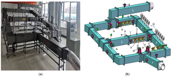
Figure 1.
Experimental equipment: (a) Physical setup. (b) Schematic diagram. Note: 1. branch 1; 2. branch 2; 3. branch 3; 4. branch 4; 5. intake airway; 6. diagonal branch; 7. return airway, 8. anemometer; 9. temperature sensor; 10. temperature string sensor; 11. carbon dioxide detector; 12. carbon monoxide detector; 13. oxygen detector; 14.air-door 1; 15. air-door 2; 16. air-door 3; 17. air-door 4; 18. air-door 5; 19. air-door 6.
Branches 1, 2, 3, and 4 are all 2.5 m long, with an inclination angle of 12°, and the diagonal branch is 3.4 m long. Ten pieces of fireproof glass are continuously set on one side of branches 1 and 2 to observe the experimental phenomenon. Downward press-in ventilation is adopted. The fan adopts a SE-A250H induction frequency axial fan with air volume ranging from 0 to 1800 m3/h. Temperature sensors are set up in the diagonal branch, branch 3 and branch 4. K-type sheathed thermocouples with a diameter of 5.0 mm are installed to measure the gas temperature beneath the ceiling of up to 1000 °C. There are 10 groups (three temperature sensors in each group, 2 cm, 10.5 cm, and 19 cm from the top plate; the group spacing is about 45 cm) of temperature string sensors along branches 1 and 2. A KV621P two-way wind velocity transmitter is equipped in each branch to measure wind velocity, whose measurement range is −5~5 m/s, the measurement accuracy is 3% F·S, and the display resolution is 0.01. Gas detectors are provided in the inlet section of branch 1, the exhaust section of branch 2, and the diagonal branch. The gas detector used is an SGA-500B fixed gas sensor, which has a detection range of carbon monoxide of 0~5000 ppm, the detection range of carbon dioxide is 0~20,000 ppm, and the detection range of oxygen is 0~30% VOL.
The oil pan is set at 3.8 cm at the entrance of branch 1 with a diameter of 10 cm, a height of 5 cm near the downwind side and 2 cm near the upwind side, which is fueled by kerosene, supplied by an external oil pump during the experiment, and ignited by an electric spark ignition. The heat release rate is an important characteristic parameter of the fire source, which can be estimated according to the principle of oxygen consumption; when combustible combustion is oxygen-rich, the heat release rate of the fire source can be calculated by Equation (1) [30].
where: X0 is the volume fraction of oxygen entering the system (%); XS is the volume fraction of oxygen in the smoke exhaust duct (%); is the volume flow rate of air entering the system before the fire (m3/s); is the volume flow rate of gas in the exhaust duct before the fire (m3/s); is the density of oxygen in the initial environment (kg/m3); E is the heat generated by the conversion of carbon into carbon dioxide, consuming a unit mass of oxygen, taken as 13.1 MJ/kg.
As shown in Figure 2, in the above experimental system, a ventilation network with parallel branches can be constructed by closing air-doors 3 and 4 located in the diagonal branch; a simple diagonal ventilation network can be constructed by keeping the air-doors fully open. In order to study the influence of the closing degree of the air-doors, which are adjacent to the fire source on the back-layering, two test cases are set up when the back-layering occurs in the ventilation network with parallel branches at three ventilation velocities: closing air-door 5 on the return side of the branch, which is adjacent to the fire source and half closing air-door 5. According to the test results, the influence of the position of the air-doors, which are adjacent to the fire source on the back-layering is studied in the ventilation network with a diagonal branch, and two cases are set up to regulate air-door 1 on the inlet side of the branch, adjacent to the fire source, and air-door 5 on the return side of the branch, adjacent to the fire source. The stable stage of a fire is selected for smoke control since the fire source releases the highest heat with the farthest back-layering length and the greatest fire hazard. To reduce the effect of the local vortex, the wind velocity values in the experiment are taken as the average value within 1 min. The experimental ambient temperature is about 20–25 °C. The experimental working conditions are shown in Table 1 and Table 2.

Figure 2.
Schematic diagram of the experimental system after the air-doors regulation: (a) Ventilation network with parallel branches. (b) Ventilation network with a diagonal branch. Note: 1. Velocity, temperature; 2. Velocity, carbon dioxide, carbon monoxide, oxygen; 3. Velocity, temperature; 4. Velocity, temperature; 5. Velocity, carbon dioxide, carbon monoxide, oxygen; 6. Velocity, temperature; 7, 8. Temperature string; 9. Velocity, temperature, carbon dioxide, carbon monoxide, oxygen.

Table 1.
Ventilation network with parallel branches scheme setting.

Table 2.
Ventilation network with a diagonal branch scheme setting.
3. Results and Discussion
3.1. Effect of Air-Door Closing Degree on the Back-Layering Flow
3.1.1. Smoke Back-Layering Length
Figure 3 presents the smoke back-layering length for the different experimental cases when the fire is stable in the ventilation network with the parallel branches without smoke control measures. If a fire occurs in an inclined roadway, the stack effect drives the hot smoke, produced by the burning, to propagate upstream. At the position where the driving force generated by the thermal buoyancy of the countercurrent gas is equal to the force of the longitudinal ventilation, the upstream back-layering front stops propagating. The distance between this stagnation position and the fire source is taken as the back-layering length. Figure 3 shows that when the wind velocity is constant, the greater the heat release rate, the farther the back-layering flow. When the ventilation velocity is 1.40 m/s and the heat release rate is 15.4 kW, the back-layering length is 2.82 m, while when the ventilation velocity is 1.40 m/s and the heat release rate is 28.0 kW, the back-layering length reaches 3.70 m, which increases the hazard to the upstream of the fire source.
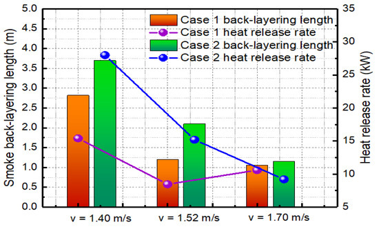
Figure 3.
Back-layering length in the ventilation network with parallel branches.
For the fire under the different ventilation velocities, when closing air-door 5, it is observed through the glass window that the smoke back-layering flow on the upstream of the fire source subsides within 1 min, and the back-layering length is 0. This is because. after closing air-door 5, the full flow of the air generated by the ventilator is directed to branch 2, where the air volume and the force of the longitudinal ventilation increases. The force of the longitudinal ventilation is greater than the driving force generated by the thermal buoyancy, and therefore the back-layering is prevented. When air-door 5 is half closed, the ventilation velocity is 1.40 m/s and the heat release rate is 28.0 kW, after 5 min of smoke control, the force of the longitudinal ventilation balances the driving force generated by the thermal buoyancy and therefore the back-layering is prevented.
3.1.2. Wind Velocity Variation in Adjacent Branch
The variation in the wind velocity in adjacent branch 3 before and after the smoke control are presented in Figure 4. As can be seen from Figure 4, the wind velocity in branch 3 gradually increases with the development of the fire at different ventilation velocities. In the experimental system, branches 1, 2, 3, and 4 are all inclined roadways. The experiment adopts a downward ventilation, and the buoyancy effect and throttling effect, generated by the fire, are opposite to the direction of the mechanical air supply, which hinders the air flow, so the air volume flowing into branch 2 decreases. As branch 3 and branch 2 are parallel roadways, and the external air supply and cross-section are unchanged, the wind velocity of branch 3 increases. Under different ventilation velocities, both the throttling effect and the buoyancy effect of the fire are different, and the increase in wind velocity in branch 3 is also different. When the ventilation velocity is 1.40 m/s and the heat release rate is 28.3 kW, the back-layering length is the farthest, which is 3.70 m. The air flow velocity of branch 3 increases from 0.68 m/s to 0.94 m/s, an increase of approximately 38.2%, which is greater than in other cases.
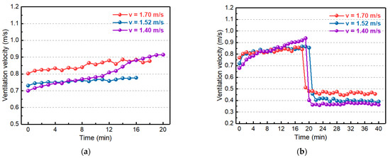
Figure 4.
Wind velocity of adjacent branches for different schemes: (a) Air-door 5 closed. (b) Air-door 5 half closed.
The inclination angle of branches 1 and 2 is 12°, and the critical velocity for the different schemes are shown in Table 3, based on the results of previous studies [20]. After closing air-door 5, branch 3 is basically windless. When air-door 5 is half closed, the ventilation velocity is 1.70 m/s and 1.52 m/s, after the air flow control. the wind velocity of branch 2 is greater than the critical velocity, and the back-layering flow subsides; additionally, the wind resistance of branches 1 and 2 become smaller, so the air volume flowing to branches 1 and 2 increases. Branches 1, 2, and branch 3 are all parallel branches, the total air volume and the cross-section of the roadways are constant, so the wind velocity of branch 3 decreases rapidly and then subsequently stabilizes. The wind velocity of branch 3, on average, quickly stabilized at around 0.47 m/s and 0.40 m/s. When the ventilation velocity is 1.40 m/s, after the air flow control, the wind velocity of branch 2 is less than the critical velocity; however, the wind velocity in branch 2 increases at the stagnation point of the wind flow and the smoke flow, the force produced by the longitudinal ventilation increases, and while the heat released from the fire source continues to decrease, with the consumption of fuel, the kinetic energy gained by the back-layering flow continues to decrease, so the driving force generated by the thermal buoyancy continues to decrease. Under the action of the longitudinal ventilation, the hot back-layering flow retreats to the fire source, and the back-layering length becomes shorter. The influence of the fire source branch on the wind flow of the wind network becomes smaller, and the wind velocity of branch 3 is relatively stable.

Table 3.
Wind velocity in the ventilation network with parallel branches after the smoke control.
3.1.3. Temperature Variation on the Upwind Side of the Fire Source
Figure 5 presents the temperature variation on the upwind side of the fire source, when the ventilation velocity is 1.40 m/s in the ventilation network with the parallel branches (the fire source is located at the origin, and the negative value indicates the distance between the upwind side of the fire source). From Figure 5, we can see that the temperature on the upstream of the fire source decreases with the increase in the distance away from the fire source before the smoke control. The reason for this is because it is under the action of buoyancy, the back-layering flow pulls the surrounding cold air and spreads forward, and the temperature near the fire source on the upwind side increases first. As the smoke flows forward, the temperature far from the fire source gradually increases. The heat exchange between the high-temperature back-layering flow with the cold air and the wall causes the velocity and the temperature of the smoke front peak to decrease until the back-layering flow reaches the stagnation point, and the temperature returns to ambient. As shown in Figure 5a, when the ventilation velocity is 1.40 m/s, before the smoke control, the highest temperature is 65 °C at 0.44 m upwind from the fire source, and the back-layering flow does not reach to 3.09 m on the upstream of fire source, the temperature is about 20 °C.
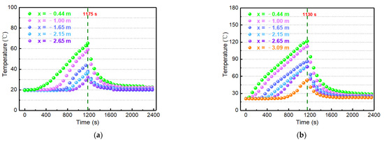
Figure 5.
Temperature variation on the upstream of fire source for different schemes when the ventilation velocity is 1.40 m/s: (a) Air-door 5 closed. (b) Air-door 5 half closed.
According to Figure 5a, fires at different ventilation velocities, after closing air-door 5, the wind velocity of branch 2 is greater than the critical velocity, and the hot smoke on the upwind side retreats to the fire source within 1 min under the driving force of the wind flow. The cold air exchanges heat with the hot air and the wall surface, and the temperature on the upwind side of the fire source rapidly decreases. Figure 5b shows that when the ventilation velocity is 1.40 m/s and air-door 5 is half closed, the wind velocity of branch 2 is less than the critical velocity, after the smoke control. With the increase in the wind velocity in the roadway, the dynamic pressure produced by the longitudinal ventilation increases under the action of the longitudinal ventilation; the hot smoke then retreats towards the fire source, and the temperature decreases at different locations in the upwind side of the fire source.
3.2. Effect of Air-Door Closing Location on the Back-Layering Flow
3.2.1. Smoke Back-Layering Length
Figure 6 shows the back-layering length in branch 1 and branch 2 for the different schemes when the fire is stable in the ventilation network with a diagonal branch and without smoke control. Under different experimental conditions, the driving force generated by the thermal buoyancy and the force of the longitudinal ventilation are different, so the back-layering length is different. When the ventilation velocity is 1.90 m/s and 1.79 m/s, the back-layering length is shorter, which is 0.25 m and 1.08 m respectively. The smoke flow does not backflow to the diagonal branch and branch 1. When the ventilation velocity is 1.70 m/s and 1.56 m/s, the back-layering flow spreads to the diagonal branch and branch 1; additionally, when the ventilation velocity is 1.70 m/s, the heat release rate is 19.5 kW, the smoke back-layering flow spreads to branch 1 and reaches to 1.50 m from the fire source. Fires at different ventilation velocities, regardless of whether measures are taken to close air-door 1 or 5, after the smoke control, show that the force of the longitudinal ventilation is greater than the driving force generated by the thermal buoyancy, and the back-layering is prevented. It is observed through the glass window that the upstream smoke flows backwards, towards the fire source, with a smoke back-layering length of 0.
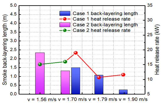
Figure 6.
Back-layering length in the ventilation network with a diagonal branch.
3.2.2. Wind Velocity Variation in Ventilation Network
Figure 7 presents the wind velocity variation in each branch for the different schemes. As can be seen from Figure 7, when the ventilation velocity is large, the fire has little effect on branch 3. For example, the ventilation velocity is 1.90 m/s, the wind velocity of branch 3 is basically unchanged. In the diagonal branch, when the air flow reaches branch 4, the velocity shows a positive value and when the air flow reaches branch 2, the velocity is negative. As seen in Figure 7, the wind velocity of the diagonal branch increases with the development of the fire, which is a result of the increase in the ventilation resistance of branch 2 as well as the air volume of branch 1 to the diagonal branch due to the thermal effect of the fire zone. The wind velocity in branch 4 also increases as the air flow from the diagonal branch is directed towards branch 4. For example, when the ventilation velocity is 1.56 m/s, the combustible material burns more intensely, the smoke flow backs up towards both the diagonal branch and branch 1, and the wind velocity increases by 19.2% for branch 3, 36% for the diagonal branch and 22% for branch 4.
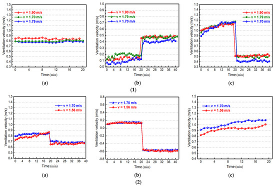
Figure 7.
Wind velocity variation for different schemes: (1) Air-door 1 closed: (a) Branch 3. (b) Diagonal branch. (c) Branch 4. (2) Air-door 5 closed: (a) Branch 3. (b) Diagonal branch. (c) Branch 4.
According to Figure 7, the fire at the different ventilation velocities and closing air-door 1, shows that the wind flow is directed towards branch 1, with branch 3 being essentially windless; the wind velocity increases in the diagonal branch, and branch 4 stabilizes after a rapid reduction in the wind velocity. Based on the previous research results [20], the critical velocity of branch 2, in the different schemes, is shown in Table 4. It can be seen from Table 4 that the wind velocity of branch 2 is greater than the critical velocity after the smoke control. The smoke back-layering flow subsides, and the wind flow of the ventilation network is redistributed and stabilized. Similarly, when air-door 5 is closed, the wind velocity in branch 3 is rapidly reduced and then restored to a stable level, and the wind flow of branch 3 is directed to the diagonal branch and branch 4 is basically windless. For example, if the ventilation velocity is 1.70 m/s, when air-door 1 is closed, the wind velocity of the diagonal branch increases rapidly and then stabilizes at 0.42 m/s, the wind velocity of branch 4 decreases rapidly to 0.40 m/s, and the wind velocity of branch 2 is 1.28 m/s. When air-door 5 is closed, the wind velocity in branch 3 decreases rapidly and then stabilizes at 0.69 m/s, the wind velocity in the diagonal branch increases rapidly and then stabilizes at 0.58 m/s, and the wind velocity in branch 2 is 1.56 m/s. When compared with closing air-door 1, the wind velocity to branch 2 is greater after closing air-door 5. The greater the wind velocity, the more likely the smoke back-layering flow will subside under the action of wind pressure.

Table 4.
Wind velocity in the ventilation network with a diagonal branch after the smoke control.
3.2.3. Temperature Variation in Ventilation Network
Figure 8 depicts the temperature variation under the roadway roof before and after the smoke control when the ventilation velocity is 1.70 m/s. The temperature variation, over time, for branch 2 on the upstream of the fire source before and after the smoke control is shown in Figure 8(1), and the temperature variation for the diagonal branch before and after the smoke control is shown in Figure 8(2). According to Figure 8(1), after adopting different smoke control schemes, the smoke back-layering flow of the fire source in branch 2 subsides, and the temperature upwind of the fire source decreases rapidly and then returns to an ambient temperature. It can be seen from Figure 8(2) that when the ventilation velocity is 1.70 m/s the temperature of the diagonal branch decreases rapidly, after adopting different smoke control schemes. After closing air-door 5, the wind velocity of the diagonal branch increases with the air flow force of the diagonal branch being greater than the driving force of the smoke flow, which results in the diagonal branch reversing the smoke flow back to the fire source. When closing air-door 1, the smoke back-layering flow from the fire source to branch 2 subsides and no more smoke flow is retrograded to the diagonal branch. After the smoke has retreated to the diagonal branch it is then diluted by the air flow, discharged through branch 4, and the temperature of the diagonal branch decreases.
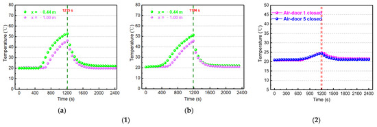
Figure 8.
Temperature variation for different schemes when the ventilation velocity is 1.70 m/s: (1) Temperature variation at different locations upstream of the fire source: (a) Air-door 1 closed. (b) Air-door 5 closed. (2) Temperature variation in the diagonal branch.
4. Conclusions
Based on the mine ventilation network test platform, the influence of the air-door position in the branch adjacent to the fire source on the characteristics of smoke back-layering was analyzed when the back-layering occurred in the mine ventilation network with a diagonal branch. To simplify the experiment, the influence of the closing degree of the air-doors, which were adjacent to the fire source on the back-layering in the mine ventilation network with parallel branches was first investigated. The main conclusions are as follows:
- (1)
- In the ventilation network with parallel branches, the back-layering occurs in the upstream region under different ventilation velocities. The closing degree of the air-doors in the adjacent branch is regulated. When the air-door on the return side of the adjacent branch is closed, the back-layering flow at different ventilation velocities subsides rapidly, and the upstream temperature tends towards ambience after a rapid reduction. When the air-door is half closed, and the ventilation velocity is 1.40 m/s, there is still back-layering flow before the fire enters the attenuation stage. Compared with the half closing of the air-door, the closing of the air door on the return side of the adjacent branch is more effective in preventing the upstream back-layering flow;
- (2)
- In the ventilation network with a diagonal branch, when the ventilation velocity is 1.70 m/s, the back-layering flow spreads to the diagonal branch and branch 1. The longest distance between the back-layering flow of branch 1 and the fire source is 1.50 m, and the wind velocity in the adjacent branches and the diagonal branch increases.
- (3)
- Bases on the experimental results in the ventilation network with the parallel branches, the air-doors at different positions of the adjacent branch are regulated. When the air-door on the return side of the adjacent branch is closed, the back-layering rapidly subsides, the wind velocity of branch 3 stabilizes at 0.69 m/s after a rapid decrease, and the wind velocity of the diagonal branch increases rapidly and then stabilizes at 0.58 m/s. When the air-door on the intake side of the adjacent branch is closed, the upstream smoke flow rapidly subsides, and the smoke in the diagonal branch spreads to the adjacent branch. In the mine ventilation network with a diagonal branch, closing the air-door on the return side of the adjacent branch is more effective in preventing back-layering in roadway fires than closing the air-door on the intake side.
Author Contributions
Conceptualization, H.W. and Z.X.; methodology, H.W., Z.X. and L.W; validation, C.F. and Y.Z.; formal analysis, H.W. and Z.X.; investigation, L.W., C.F. and Y.Z.; data curation, L.W.; writing—original draft preparation, Z.X.; writing—review and editing, H.W., Z.X. and C.F.; funding acquisition, H.W. All authors have read and agreed to the published version of the manuscript.
Funding
This research was funded by the National Natural Science Foundation of China (No. 51874313), the National Key Research and Development Program of China (2018YFC0808100).
Data Availability Statement
Not applicable.
Conflicts of Interest
The authors declare no conflict of interest.
References
- Song, Z.Y.; Kuenzer, C. Coal fires in China over the last decade: A comprehensive review. Int. J. Coal Geol. 2014, 133, 72–99. [Google Scholar] [CrossRef]
- Fernandez-Alaiz, F.; Castanon, A.M.; Gomez-Fernandez, F.; Bascompta, M. Mine fire behavior under different ventilation conditions: Real-scale tests and CFD modeling. Appl. Sci. 2020, 10, 3380. [Google Scholar] [CrossRef]
- Shi, G.Q.; Wang, G.Q.; Ding, P.X.; Wang, Y.M. Model and simulation analysis of fire development and gas flowing influenced by fire zone sealing in coal mine. Process. Saf. Environ. 2021, 149, 631–642. [Google Scholar] [CrossRef]
- Yao, Y.Z.; He, K.; Peng, M.; Shi, L.; Cheng, X.D. The maximum gas temperature rises beneath the ceiling in a longitudinal ventilated tunnel fire. Tunn. Undergr. Space Technol. 2021, 108, 103672. [Google Scholar] [CrossRef]
- Wang, Z.; Ding, L.; Wan, H.; Ji, J.; Gao, Z.; Yu, L. Numerical investigation on the effect of tunnel width and slope on ceiling gas temperature in inclined tunnels. Int. J. Therm. Sci. 2020, 152, 106272. [Google Scholar] [CrossRef]
- Jia, Q.; Wu, H.; Ling, T.; Liu, K.; Peng, W.W.; Gao, X.; Zhao, Y.L. Study on the stress variation law of inclined surrounding rock roadway under the influence of mining. Minerals 2022, 12, 499. [Google Scholar] [CrossRef]
- Yang, D.; Ding, Y.; Du, T.; Mao, S.; Zhang, Z. Buoyant back-layering and the critical condition for preventing back-layering fluid in inclined tunnels under natural ventilation: Brine water experiments. Exp. Therm. Fluid Sci. 2018, 90, 319–329. [Google Scholar] [CrossRef]
- Du, T.; Yang, D.; Ding, Y. Driving force for preventing smoke backlayering in downhill tunnel fires using forced longitudinal ventilation. Tunn. Undergr. Space Technol. 2018, 79, 76–82. [Google Scholar] [CrossRef]
- Zhou, Y.; Song, S.L.; Guo, J.W.; Xu, Y.; Lin, B.Q. Experimental study of the sequence of flow reversals in accessional airways parallel to a fire. J. China U. Min. Technol. 2009, 38, 467–470+493. [Google Scholar]
- Barbato, L.; Cascetta, F.; Musto, M.; Rotondo, G. Fire safety investigation for road tunnel ventilation systems—An overview. Tunn. Undergr. Space Technol. 2014, 43, 253–265. [Google Scholar] [CrossRef]
- Hu, L.H.; Huo, R.; Chow, W.K. Studies on buoyancy-driven back-layering flow in tunnel fires. Exp. Therm. Fluid Sci. 2008, 32, 1468–1483. [Google Scholar] [CrossRef]
- Roh, J.S.; Ryou, H.S.; Kim, D.H.; Jung, W.S.; Jang, Y.J. Critical velocity and burning rate in pool fire during longitudinal ventilation. Tunn. Undergr. Space Technol. 2007, 22, 262–271. [Google Scholar] [CrossRef]
- Oka, Y.; Atkinson, G.T. Control of smoke flow in tunnel fires. Fire Safety J. 1995, 25, 305–322. [Google Scholar] [CrossRef]
- Wu, Y.; Bakar, M.Z.A. Control of smoke flow in tunnel fires using longitudinal ventilation systems-a study of the critical velocity. Fire Safety J. 2000, 35, 363–390. [Google Scholar] [CrossRef]
- Lee, S.R.; Ryou, H.S. An experimental study of the effect of the aspect ratio on the critical velocity in longitudinal ventilation tunnel fires. J. Fire Sci. 2004, 23, 119–138. [Google Scholar] [CrossRef]
- Yi, L.; Xu, Q.Q.; Xu, Z.S.; Wu, D.X. An experimental study on critical velocity in sloping tunnel with longitudinal ventilation under fire. Tunn. Undergr. Space Technol. 2014, 43, 198–203. [Google Scholar] [CrossRef]
- Chow, W.K.; Gao, Y.; Zhao, J.H.; Dang, J.F.; Chow, C.L.; Miao, L. Smoke movement in tilted tunnel fires with longitudinal ventilation. Fire Safety J. 2015, 75, 14–22. [Google Scholar] [CrossRef]
- Atkinson, G.; Wu, Y. Smoke control in slopping tunnels. Fire Safety J. 1996, 27, 335–341. [Google Scholar] [CrossRef]
- Li, J.; Li, Y.F.; Cheng, C.H.; Chow, W.K. A study on the effects of the slope on the critical velocity for longitudinal ventilation in tilted tunnels. Tunn. Undergr. Space Technol. 2019, 89, 262–267. [Google Scholar] [CrossRef]
- Hao, H.Q.; Wang, K.; Zhang, C.Y.; Jiang, S.G.; Wang, H.K. Evolution and regulation law of wind and smoke flow field area network in mine belt roadway fire. J. China U. Min. Technol. 2021, 50, 716–724. [Google Scholar]
- Wang, K.; Jiang, S.G.; Ma, X.P.; Wu, Z.Y.; Shao, H.; Zhang, W.Q.; Cui, C.B. Information fusion of plume control and personnel escape during the emergency rescue of external-caused fire in a coal mine. Process. Saf. Environ. 2016, 103, 46–59. [Google Scholar] [CrossRef]
- Marjanovic, D.; Grozdanovic, M.; Janackovic, G. Data acquisition and remote control systems in coal mines: A serbian experience. Meas. Control 2015, 48, 28–36. [Google Scholar] [CrossRef]
- Wang, Q.J.; Ma, X.P.; Yang, C.Y.; Dai, W. Modeling and control of mine main fan switchover system. ISA Trans. 2019, 85, 189–199. [Google Scholar] [CrossRef] [PubMed]
- Xu, G.; Jong, E.C.; Luxbacher, K.D.; Ragab, S.A.; Karmis, M.E. Remote characterization of ventilation systems using tracer gas and CFD in an underground mine. Safety Sci. 2015, 74, 140–149. [Google Scholar] [CrossRef]
- Fu, M.M.; Zheng, Q.; He, S. Oxygen control mechanism in non-ventilation excavation based on the simultaneous mining of coal and gas. Process Saf. Environ. 2019, 123, 33–38. [Google Scholar] [CrossRef]
- Wang, K.; Jiang, S.G.; Ma, X.P.; Wu, Z.Y.; Shao, H.; Zhang, W.Q.; Cui, C.B. Numerical simulation and application study on a remote emergency rescue system during a belt fire in coal mines. Nat. Hazards 2016, 84, 1463–1485. [Google Scholar] [CrossRef]
- Wang, K.; Jiang, S.G.; Zhang, W.Q.; Wu, Z.Y.; Shao, H.; Liu, T.; Ju, X.R. Remote control technology and numerical analysis of airflow in coal mine fire disaster relief process. J. China Coal Soc. 2012, 37, 1171–1176. [Google Scholar]
- Shang, W.; Deng, L.; Liu, J. A novel air-door opening and closing identification algorithm using a single wind-velocity sensor. Sensors 2022, 22, 6837. [Google Scholar] [CrossRef]
- Wang, K.; Hao, H.Q.; Jiang, S.G.; Cai, W.Y.; Zhang, Y.C.; Wang, Z.T. Experimental study on the characteristics of overpressure wave to ventilation facilities during gas explosion and automatic shock relief devices. Geomat. Nat. Hazards Risk 2020, 11, 2360–2383. [Google Scholar] [CrossRef]
- Parker, W.J. Calculations of the heat release rate by oxygen consumption for various applications. J. Fire Sci. 1984, 2, 380–395. [Google Scholar] [CrossRef]
Publisher’s Note: MDPI stays neutral with regard to jurisdictional claims in published maps and institutional affiliations. |
© 2022 by the authors. Licensee MDPI, Basel, Switzerland. This article is an open access article distributed under the terms and conditions of the Creative Commons Attribution (CC BY) license (https://creativecommons.org/licenses/by/4.0/).