Abstract
There is a growing need for portable, highly sensitive measuring equipment to analyze samples in situ and in real time. For these reasons, it is becoming increasingly important to research new experimental equipment to carry out this work with advanced, robust and low-cost devices. In this framework, a flexible, portable and low-cost fluorimeter (under EUR 500), based on a C12880 MA MEMS micro-spectrometer with an Arduino compatible breakout board, has been developed for the trace analysis of biological substances. The proposed system can employ two selectable excitation sources for flexibility, one in the visible region at 405 nm (incorporated in the board) and an external LED at 365 nm in the UV region. This additional excitation source can be easily interchanged, varying the LED type for investigating any fluorophore compound of interest. The measurement process is micro-controlled, which allows the precise control of the spectrometer sensitivity by adjusting the integration time of each experiment separately. Data acquisition is easy, reliable and interfaced with a spreadsheet for fast spectra visualization and calculations. For testing the performance of the new device in fluorescence measurements, different fluorophore molecules which can be commonly found in biological samples, such as Fluorescein, Riboflavin, Quinine, Rhodamine b and Ru (II)-bipyridyl, have been employed. A high sensitivity and low quantitation limits (in the ppb range) have been found in all cases for the investigated chemicals. The portable device is also suitable for the study of other interesting phenomena, such as fluorescence quenching induced by chemical agents (such as halide anions or even auto-quenching). In this sense, an application for the quantification of chloride anions in aqueous solutions has been performed obtaining a LOD value of 18 ppm. The obtained results for all chemicals investigated with the proposed fluorimeter are always very similar in quantification figures, or even better than the data reported in literature, when using commercial laboratory equipment.
1. Introduction
Many chemical substances play a key role in living biometabolic routes and the development of new chemosensors is a key tool for analyzing their influence on this kind of process. Nowadays, a great variety of chemosensors are available with a very broad variety of bioanalysis applications [1,2]. Analytical methods based on optical properties are one of the most interesting areas due, fundamentally, to their high sensitivity and selectivity as well as low limits of detection and quantification for chemical and biochemical analysis. In particular, molecular fluorescence presents many characteristic advantages for these purposes, such as different excitation and emission wavelengths, high sensitivity with low background noise levels, molecule trace analysis, simple instrumentation compared to other light absorption techniques and the possibility for employing chromophore group sensors for non-fluorescent compounds [3].
In the recent years, there is an increasing interest in the development of organic fluorescent materials as chemical sensors [4], such as rhodamine [5], cytochrome-c [6], melamine [7], chlorophyll [8] and quercetin [9], and many other probes with important medical applications for diabetes and drug therapy [2].
Furthermore, the required instrumentation employed for fluorometric measurements has evolved in recent years from static designs mainly focused on laboratory assays towards more flexible, portable and handheld devices [10,11,12,13,14,15,16], which can be easily operated for in situ experiments. Thus, the increasing availability of the necessary components to build fluorometric detection devices, such as intense light sources with different excitation wavelengths (LEDs, fiber optic) [17,18] and compact micro-spectrometers for light analysis (C1280 MA) [19], and the existence of numerous computer-programmable microcontrollers (Raspberry Pi, Arduino) [20,21,22,23] allow the building of low-cost equipment [24,25,26] with unique features for in situ sample analysis with spectrofluorometric detection.
The development of nanotechnologies like MEMS (Micro-Electro-Mechanical Systems), also called micro-machined devices, opens a new realm of possibilities for designing microsensors and micro-actuators [27], which allows the building of highly miniaturized instrumentation with advanced sensing properties and very low energy consumption. By using MEMS technology [28,29] and focusing on fluorescent sensing applications, ultra-compact (fingertip-sized) spectrometers with high optical sensitivity in a wide wavelength region (340–850 nm) are commercially available, especially suitable for use in low-cost and portable devices.
In this work, a compact fluorescent spectrophotometer based on MEMS has been developed for easy, fast, reliable and low-cost optical sensing applications and tested for the quantitative determination of low levels of classical fluorescent probes such as fluorescein, riboflavin, quinine, thiamine (vitamin B1), rhodamine and Ru (II)-bipyridyl. The proposed device includes two selectable light excitation sources (365 and 405 nm for the UV and visible regions, respectively), is micro-controlled with an Arduino system and the experimental results are directly exported with an open-sourced interface to a spreadsheet for data manipulation and graphical visualization. Highly sensitive and reproducible spectra can be obtained, allowing very low detection limits (in the range of ppb) for different fluorescent probes. The cost of the developed system is very low compared to commercial fluorimeter equipment; it is, additionally, a portable system which can be used for in situ measurements.
2. Materials and Methods
2.1. Experimental
Chemicals were purchased from Sigma Aldrich with analytical grade: fluoresceine sodium salt, quinine sulphate, riboflavin, rhodamine B, Ru(bpy)3 (Tris(2,2′-bipyridyl)dichlororuthenium(II) hexahydrate), sodium hydroxide, sulfuric acid and acetic acid. Table 1 gathers a summary of the fluorophores tested, including their main characteristics, as well as solvents and solution concentration ranges employed for the fluorimetric measurements.

Table 1.
List of characteristics for the fluorophores tested in this study, solvent employed for the preparation of the solutions, concentration ranges investigated as well as wavelengths of excitation and emission maxima for each molecule.
Water was purified by using a Millipore system (Milli-Q Reference model) and all the measurements were performed at 25 ± 1 °C.
Hellma Suprasil precision quartz cells (type 101-QS) with 10 mm light path length have been employed for experimental measurements. Fluorescence measurements were compared with a Varian Cary-Eclipse fluorescence spectrophotometer, interfaced to a PC computer with Cary-Eclipse software for acquisition. Wavelength accuracy was ±1.5 nm, with 200–900 nm as the wavelength range for emission and excitation.
2.2. Hardware
The fluorimeter hardware is based on the C12880MA mini-spectrometer from Hamamatsu photonics [30]. The most remarkable features from its data sheet are a high sensitivity, a spectral width from 340 to 850 nm with a resolution of 15 nm, an average spectral resolution of 9 nm in the wavelength range and a rather small size (20.1 mm × 12.5 mm × 10.1 mm) with a hermetic encapsulation providing high stability against humidity and dust.
The optical sensor is based on complementary metal–oxide–semiconductor (CMOS) technology. The radiation entering the slit is reflected by a concave grating (built with MEMS technology) which scatters the radiation to the CMOS-type linear photosensor. Each of the internal photodiodes employed stores an electrical charge on a capacitor for each wavelength. The gathered electrical charge on each capacitor is proportional to both the intensity and the time interval in which the radiation has been received. This time interval is usually known as the integration time. The electric charge stored at the capacitors is converted to an output analog voltage value that can be set through the VIDEO pin of the system mainboard. The value for each wavelength is obtained sequentially by clock pulses via the CLK pin and they are read by the A/D microcontroller converter. The manufacturer provides the photodiode calibration data for each wavelength of each device individually according to its serial number.
The activation, synchronization and spectrum reading processes have to be performed by acting on the various digital lines in a sequence specified in the timing diagram, which is described in the data sheet [30]. In order to obtain the digital spectrum, the control timing diagram of the C12880MA device has to be followed, and for this purpose it is very appropriate to use some kind of microcontroller, which can be programmed to implement the measurement and readout process. This procedure will be described later in the software section.
Moreover, both the frequencies and impedances between the C12880MA spectrometer and the microcontroller must be properly matched. Fortunately, there is a compatible breakout board developed by GroupGets which provides the interface for Arduino-type microcontrollers. The breakout board v1 (which is actually an end-of-life product being replaced by version v2 [31]) provides the supply voltage stabilization and a low output impedance to the spectrophotometer signals, allowing for a direct communication with the microcontroller mainboard. In addition, the board v1 included two light sources, a white LED (not used in this project because it is designed for transmission light experiments) and a 405 nm laser [32], which can be activated independently by using a digital line from the microcontroller board. Figure 1a shows the size scale of the Hamamatsu spectrometer and Figure 1b the GroupGets breakout with the integrated components.
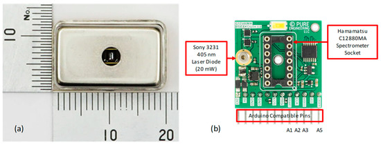
Figure 1.
(a) Top view of C12880MA from Hamamatsu photonics with size scale; (b) GroupGets breakout v.1 for Hamamatsu C1288MA spectrometer integration with Arduino microcontrollers. A1, A2, A3 and A5 pins correspond to the analog inputs assigned to monitor the START, CLK, VIDEO and LASER control lines on the Arduino compatibles microcontrollers.
For building the fluorimeter, a square flat mirror of 6.6 mm side has been used. The mirror was placed at a 45-degree angle, allowing the reflection of the laser light so that it could reach the sample compartment, which was located perpendicularly to the C12880MA input slit (see Figure 2). In order to make the prototype more flexible and functional, an extra excitation light source was included on the opposite side of the mirror. For this purpose, an interchangeable LED (attached to the system by using magnetic linkage) allowed for a selectable wavelength source to be readily available. In this project, a 365 nm UV LED (with a power of 20 mW for optical applications) was chosen, which provides a versatile wavelength in fluorescence studies, but it can be easily replaced by other wavelength excitation sources if necessary. The optical cell was covered with a black lid to prevent any external radiation from reaching the measurement compartment.
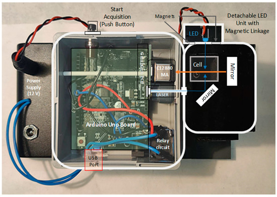
Figure 2.
Schematic diagram overlaid to the real fluorimeter picture, showing the configuration of the measurement cell, the mirrors location for a proper light path and the employed excitation sources: the integrated Laser (405 nm) and the interchangeable UV-LED unit (365 nm).
The interchangeable LED was powered from an additional external 12 V supply (using a classic transistor-actuated relay circuit) which allowed the preservation of the microcontroller power supply without overloading it. The electrical diagram of the external supply is included in the Supplementary Section.
As microcontrollers, different models of compatible Arduino boards were tested for the developed fluorimeter: Uno [33], Mega 2560 [34] and Zero (an extended version of the Arduino Uno). The main technical specifications related to this project for each of them are gathered in Table 2.

Table 2.
Main hardware specifications of the compatible Arduino microcontrollers used in the portable fluorimeter development.
Additionally, a modification affecting the VIDEO pin of the GroupGets breakout board was made to adapt the C12880MA standard board output voltage (5 V) to the Arduino Zero circuit operating voltage (3.3 V), which was also the maximum value supported by its A/D converter. For this purpose, a classical voltage divider was designed by choosing the proper resistance values. This modification is completely reversible to the original configuration, if necessary (see the Supplementary Section for more details about the employed electrical circuit). This adaptation proved to be very efficient for obtaining a higher measurement resolution when using a WeMos microcontroller based on a 32-bit SAMD21 microprocessor family [35], which has many advantages such as a high processing speed, high memory capacity and, especially, a 12 bits A/D converter. In this way, it was possible to gain a resolution four times higher than in the microcontrollers with a 10 bits A/D converter.
Other materials used were a Digital Oscilloscope from Rigol model DS1054 with four channels with 50 MHz maximum clock frequency, a flat mirror (6 mm × 6 mm) purchased from Edmund Optics, SMD 1% resistors, SRD-12VDC-SL-C relay, SMD 2N2222 transistor and a diode type 1N4007.
2.3. Software
The control and data acquisition program for the C12880MA was adapted for the different microcontroller boards employed (listed in Table 2), keeping the compatibility of the pinout assignment with the GroupGets breakout board described in the hardware section. Accordingly, the testing of the different microcontrollers was performed by simply plugging-in or plugging-out the C12880MA breakout board. Thus, the assignment of the control pins remained unchanged between the different developed programs.
As a general rule of working, the developed code was implemented to obtain a single averaged emission spectrum of either the blank or sample solution. The developed program had the classic structure of microcontrollers code, as indicated in the flow diagram of Figure 3: (i) a first block of variable and type definitions that will have a global scope of use (INIT), (ii) the pin assignment and its mode of operation and the initialization of the default variable values and the resolution of the A/D converter (SETUP), (iii) the serial communication port activation and the interface with the spreadsheet initialization for parameters input and measurement data visualization and, finally, (iv) the measurement process, which is executed in a loop form (LOOP).
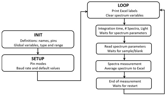
Figure 3.
Schematic flow diagram corresponding to the program code for performing the experimental measurements.
The entire measurement process was controlled by a simple pushbutton associated with a digital input (D12) of the microcontroller. At the beginning, the program waits for the user to perform several operations, such as the definition of the input variables: the integration time (10–2,000,000 µs), the number of spectra for an averaged result (1–1000 spectra) and the selection of the wavelength excitation light source (365 or 405 nm depending on whether the external LED or the on-board laser source is selected). These variables are read and checked from a spreadsheet that includes the PLX_DAQ serial communication add-on [36], which activates the communication through the microcontroller USB connection port. This free add-on is especially useful because it enables the sending of external parameters to the microcontroller program code (both in input/output mode), avoiding the compiling of the entire code each time a variable is changed. Furthermore, it also serves as a communication interface with the user to display measurement warnings and/or operation requests. The installation, programming and use of this add-on in related applications has been previously described in the literature [37,38,39].
Once the pushbutton is actuated, the main microcontroller program calls the C12880MA control and measurement subroutine, accumulating the number of the selected spectra. Once the accumulation is finished, the averaging process is performed and the results are sent to the spreadsheet via the PLX_DAQ module add-on. Thus, the averaged spectrum is stored in two columns of the spreadsheet: one for the radiation wavelength and another one for the emission intensity, allowing for a fast graphical representation and easy further data manipulation.
Depending on the microcontrollers clock speeds listed in Table 2, it is possible to develop two different types of subroutines for controlling the measurement procedure with the C12880MA, defined as fast or slow. The first one requires a low-level of programming, allowing for a faster acquisition. The second one uses high-level function calls, which significantly slow down the acquisition rate. A detailed description of the routines employed in each case is provided in the Supplementary Section.
The “readSpectrometer” acquisition routine controls the logical levels of the GroupGets breakout board pins: START (A1), CLK (A2), VIDEO (A3) and LASER (A5), which are shown in Figure 1b, by using the timing diagram depicted in the spectrometer specifications datasheet [30]. The external LED is controlled by means of the digital output (D9) of the microcontroller board. The measurement procedure begins with setting the START pin to high level (1) and waiting for three clock pulses on the CLK pin. By using the integration time variable indicated in the spreadsheet, a specified number clock cycles are sent to the “pulse_clock” routine which allows the increasing or decreasing of the amount of light reaching the internal photodiodes of the spectrometer. Next, the START pin is set to low level (0) and 48 pulses on the CLK pin are required to complete the integration time, which exactly defines the end of the capacitors’ charging process associated with each photodiode. An additional 40 cycles on the CLK pin are necessary to collect the whole spectrum, which is stored sequentially in a memory array whose data are accessible through the VIDEO pin. In addition, this routine also controls the pins to switch on and off the selected excitation light source, LASER (A5) or LED (D9). Figure 4 shows the digital timing signals corresponding to a single measurement process for the START (yellow line), CLK (cyan line) and LASER/LED (violet line) pins. Data were collected by using a digital oscilloscope for an integration time of approximately 2 ms. As shown, the excitation light is set to a high level a short time before the acquisition starts and it is set to a low level very shortly after finishing the acquisition.
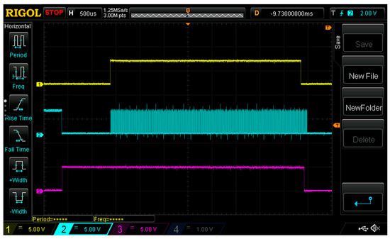
Figure 4.
Digital oscilloscope screenshot showing the timing diagram corresponding to a single spectrum acquisition. Yellow: START pin (start/stop), Cyan: CLK pin (clock), Magenta: LASER/LED pin (on/off) for the activation of the excitation light. Approximate integration time: 2 ms.
Spectrum measurement is a very fast procedure that can be completed in a few milliseconds, which allows the average of the experimental measurements to significantly improve the signal-to-noise ratio in relatively short time periods. This is one of the main advantages of the proposed system.
Intermediate time counters have been included in the measurement subroutines to accurately determine the time required to carry out each of the involved stages. This strategy allows the establishing of the real value for the integration time on each measurement, which mainly depends on the type of subroutine employed (fast or slow) and, consequently, on the microprocessor itself. Therefore, the emission intensity measurements obtained for a given spectrum mainly depend on the integration time used. In order to compare spectra made with different integration times, it is necessary to obtain the value of the emission intensity per unit of integration time. Taking into account the excellent linear relationship between the real integration time and the value entered as a parameter in the spreadsheet, either of them can be used as a scaling factor (see the Supplementary Section for more details).
The usual procedure for measuring a fluorescence spectrum of a chemical sample consists of the acquisition of the blank and sample solutions by using the same parameters: integration time, number of measurements and type of excitation light.
Blank subtraction can be easily completed directly in the spreadsheet to obtain the final results. The Supplementary Section contains detailed information about the blank and sample subtraction procedure. During the short measurement time, it is advisable not to use the spreadsheet or the computer to ensure the correct transmission of data through the USB port.
3. Results and Discussion
3.1. Integration Time
The first interesting parameter to analyze in the proposed system, as was stated in the software section, is the relationship between the actual integration time and the time entered in the spreadsheet. Figure 5 shows the outstanding linear relationship between both integration times. The reproducibility is excellent for any type of microcontroller and programs tested, with errors in the slope and intercept being less than 0.002% and close to 1%, respectively. From this excellent linear behavior, the estimation of the relative spectrum intensity at different integration times can be performed employing any of these time values as a conversion factor, the usage of the actual value which corresponds to the real one being recommended. Thus, there is a small difference when using the high-level programming procedure for the UNO, 2560 and ZERO microcontrollers, with a clock frequency around 100 kHz. For the fast programing procedure, the clock frequency obtained is seven times faster (750 kHz) when UNO and MEGA 2560 microcontrollers are employed.
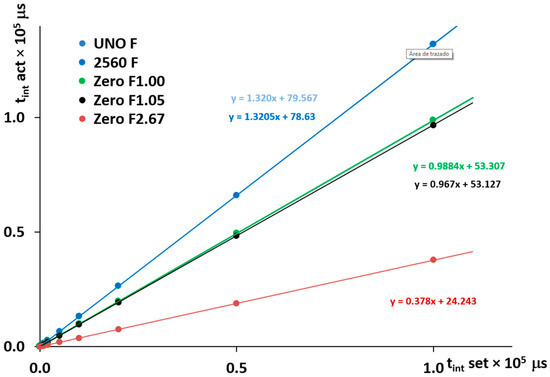
Figure 5.
Comparison between the actual integration time obtained and the values entered in the Excel spreadsheet as input parameters. Data correspond to the fast-programing level. ZERO board: orange at 2.67 MHz, black at 1.05 MHz and green at 1.00 MHz, UNO board: pale blue at 750 kHz, MEGA 2560: dark blue at 750 kHz.
Nevertheless, the fast programing allows the clock frequency to reach up to 2.67 MHz in the case of the ZERO microcontroller. Therefore, modifying the delay instructions is possible to accurately adjust the clock frequency to a 1 MHz value. As is shown in Figure 5 (green and black lines), it is possible to establish a direct correspondence between the integration time entered as parameter in the datasheet and the actual integration time obtained. The Supplementary Section contains additional information about the port assignations and the programing procedure followed for each case.
Dark intensities in the absence of chemical fluorophores have been recorded for one, four, twenty and forty averaged spectra to measure the noise level of the developed system. The S/N ratio is increased by the square root of the spectra number (), thus it can be increased 10 times in a short measurement time when averaging a hundred of spectra.
3.2. Experimental Emission Spectra
A systematic and quantitative study for solution trace analysis in the solution has been performed, using the fluorophores listed in Table 1, to test the proposed fluorimeter with the two available excitation sources. The summarized results for 1 µM solutions in each case are shown in Figure 6.
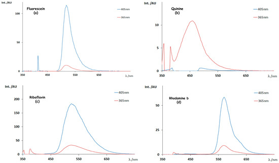
Figure 6.
Fluorescent spectra for different fluorophores samples: (a) Fluorescein; (b) Quinine; (c) Riboflavin; (d) Rhodamine. Excitation light: 405 nm (LASER, blue lines) and 365 nm (UVLED, red lines). All samples contain a 1 µM solution of the indicated fluorophores.
As a general rule, the emission wavelength maxima are nearly independent from the radiation energy employed. The implementation of 365 nm excitation light is clearly justified for the study in the case of quinine. Semi quantitatively in Figure 6, the fluorescence intensity is higher for the 405 nm excitation source, especially in the case of fluorescein, riboflavin and rhodamine b, as described in the data in the literature [40,41,42,43].
Figure 7 includes all the fluorescence spectra obtained for quinine at different concentration levels by using the excitation source at 365 nm (LED), as a representative fluorophore. For clarity, the inset incorporated in Figure 7 shows the experimental spectra in the dilute range.
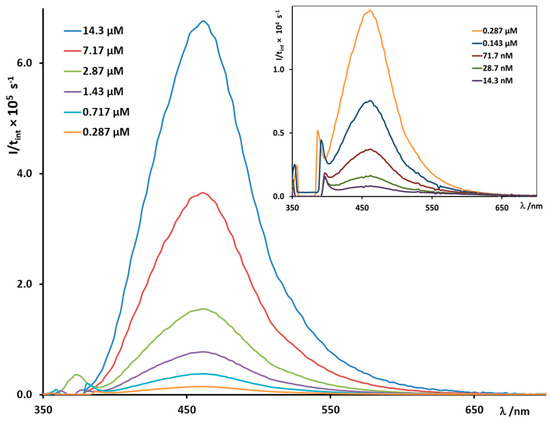
Figure 7.
Experimental fluorescence spectra obtained for quinine at worked concentration levels, by using the excitation source at 365 nm (LED). The inset shows the experimental spectra for the most dilute solutions.
3.3. Analytical Validation
The developed system has also been tested for a quantitative study to determine the linear response range and the quantification/detection limits for the fluorophores listed in Table 1. LOD and LOQ values were calculated as three- and ten-times signal-to-noise ratios, respectively [44]. These results are depicted in Table 3.

Table 3.
Figures of merit for the quantification analytical results of the fluorophores analyzed in this work with the proposed equipment, by using logarithmic calibration curves. LOD: limit of detection; LOQ: limit of quantification.
As can be seen, wide linear ranges were obtained for all chemical compounds, ranging from nanomolar to micromolar concentration levels. Very low LOD (0.1–7.2 nM) and LOQ (0.4–23.9 nM) values were found for rhodamine B, fluorescein, riboflavin and quinine. Ru (bpy)3 is less sensitive to fluorescence emission and, accordingly, higher values in the micromolar range were obtained. In all cases, a great linearity above 98% was found. In order to evaluate the repeatability and intermediate precision, replicate measurements were done in one single day and two days per week for three weeks, respectively. Relative standard deviation (RSD%) values were obtained in the ranges 1–3% for repeatability and 6–10% for intermediate precision.
As a representative fluorophore, Figure 8 shows the calibration plot (log I/ti vs log C) for quinine, obtained from peak intensity values at the maximum emission wavelength. This case represents the best linearity value achived among all the investigated fluorescent compounds (see Table 3).
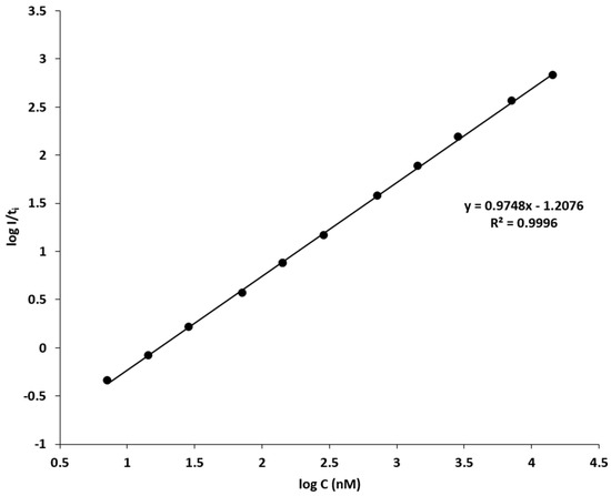
Figure 8.
Logarithmic calibration plot for quinine, obtained from the fluorescence emission maxima of the experimental spectra, showed in Figure 7.
The obtained results for the calibration standards in the case of quinine can be directly compared with the data in the literature [45], when using the Perkin Elmer FL6500 fluorescence spectrometer with an excitation source of 350 nm. With this commercial equipment, the LOD value for quinine sulphate under the same experimental conditions is 11.5 nM (or 0.009 ppm) which is even slightly higher than the value obtained in this work (7.2 nM or 0.006 ppm). The high sensitivity achieved by the present portable system for fluorescence measurements is remarkable, confirming its potential use for molecular trace analysis.
Additionally, optical chloride anion sensing can be performed by using a fluorescence quenching method, where the fluorescence intensity (I) is diminished for the presence of the quencher agent (Q), according to the Stern–Volmer kinetics equation [43]:
where I0 corresponds to the fluorescent emission intensity in the absence of quencher and KSV is the Stern–Volmer kinetic constant. Figure 9 shows the comparative results by using the Varian Cary-Eclipse and the proposed fluorimeter for quinine (sulphate) quenched by chloride anion in aqueous solution, according to Equation (1).
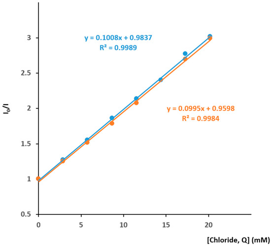
Figure 9.
Typical Stern-Volmer plot for the quinine (sulphate) quenched by aqueous solution of chloride ions. Blue: commercial Varian Cary Eclipse spectrometer. Orange: this work.
A good linear relationship is found both with the Varian Cary-Eclipse spectrometer (λexc = 346 nm, λem = 450 nm) and the present portable device (λexc = 365 nm, λem = 460 nm). As can be noted from the linear regression data, very similar results are obtained in both cases even using a slightly different excitation wavelength, resulting in LOD values for chloride anions in solutions of 0.5 mM (17.8 ppm) and 0.6 mM (21.3 ppm), respectively. This methodology is a very interesting application for analyzing halide anions in biological samples offering high sensitivity, as shown in the literature [46].
In all practical applications presented in this work, the proposed device is at least as powerful as other commercial spectrometers, showing comparable LOD values for the analysis of different fluorescent samples. Furthermore, it is important to remark upon its key features: it is an easy to use, versatile, compact and portable device, available at a very low budget (less than EUR 500 in total). These features make the developed equipment a very promising alternative to classical laboratory spectrometers with many applications for different fields (portable devices, rapid analysis, biological samples, trace analysis, low price, improved signal to noise ratio, etc.), where the fluorescence spectroscopy is the main analytical tool. In addition, this system could be easily adapted with a SMA connector attached to the C12880MA for using with an optical fiber, extending the possibilities for analysis of different sample types and improving the overall flexibility. Lastly, with slight changes in the global design (both hardware and software), it could also be possible to perform light absorption measurements at the visible region. Furthermore, it could even be adapted to perform Raman spectroscopy using a more powerful excitation source (typically a laser ranging from 532 nm to 785 nm) and taking advantage of some features developed for this prototype, such as the variable integration time and the spectra averaging procedure. In this case, the cell geometry should also be modified.
In Table 4, the main characteristics of the presented fluorimeter are compared with other commercial devices designed for similar purposes. Commercial solutions are normally found as a bundle pack which include all the components required for the fluorescence measurements. Generally, the overall cost of this kind of equipment is higher and they offer less flexibility. The portable device described in this work is affordable compared with the commercial solutions and it offers very interesting results for fluorescence measurement for molecule trace analysis, as it is shown in this work.

Table 4.
Principal features of commercial (bundle packs) and the proposed device for fluorescence measurements. * Optional accessories which are sold separately.
4. Conclusions
In this work, a versatile, portable and low-cost fluorimeter based on a C12880MA MEMS micro-spectrometer controlled by Arduino-compatible breakout boards with different hardware capabilities, has been developed for low-limit chemical quantification by means of fluorescent measurements.
The obtained results for different fluorescent probes have been compared with standard laboratory equipment allowing the obtaining of, at least the same (if not better) quantification levels for trace analysis (ppb ranges). At the same time, data acquisition is exported directly to an Excel spreadsheet by means of a freely distributed add-on which enables fast data analysis. Its ease of operation is an additional advantage for inexperienced users, as very simple actions are required, using only the spreadsheet for data parameter input.
All these advantages make the proposed system very suitable for in situ sample analysis, expanding the possibilities as a very capable portable system. The global budget of this system is less than EUR 500 but offering similar results in chemical analysis to traditional laboratory equipment has at least a ten times higher cost. Finally, the possibility of extending the system capabilities with minimal changes in the final design, improving flexibility in the sample analysis, is remarkable.
Supplementary Materials
The following are available online at https://www.mdpi.com/article/10.3390/chemosensors11070389/s1, Figure S1. (a) External detachable UV-LED 365 nm unit employed in this work. Two internal small disk magnets allow the proper alignment of the light source in the right place. (b) Schematic electronic components used for the extra source light control. R1 = 10 kΩ, D1 = 1N4007, TR1 = 2N2222, R2 = 110 Ω, RL1= SRD 12VDC SL C, UV LED 365 nm 1W, Figure S2. External UV-LED unit (365 nm) illuminating a fluorescent quinine sample. Figure S3. Internal design of the measurement cell when the 405 nm laser unit is employed. The incident light reaches the flat mirror at 45o which allows the illumination of the fluorescent sample. Figure S4. (a) Electrical scheme of the voltage divider employed on the GroupGets breakout board. (b) The output VIDEO pin pass through the voltage divider before being redirected into the microcontroller board. Figure S5. Oscilloscope snapshot for the generation of a 1MHz CLK square wave signal (cyan). ST signal is in high state (yellow) and LIGHT signal is in low state (pink) during the measurement process. The signals are generated with the Zero microcontroller by using a 3.3 V voltage level. Figure S6. Oscilloscope snapshot for the timing of a single spectrometer measurement. CLK signal (cyan), ST signal (yellow) and excitation light (purple). The integration time is approximately 26 µs, which contains 48 CLK pulses. The following 40 CLK pulses are necessary to match the microprocessor data output string to the classical spectrum format. Figure S7. Fluorescent spectrum magnified, for 1 µM Fluorescein (blue line) compared with its associated blank spectrum (black line) corrected from the dark current. Excitation light: 405 nm. Figure S8. Fluorescent spectrum magnified, for 1 µM Fluorescein (red line) compared with its associated blank spectrum (black line), corrected from the dark current. Excitation light: 365 nm. Figure S9. Fluorescent spectrum magnified for 1 µM Quinine (red line) compared with its associated blank spectrum (black line) corrected from the dark current. Blue arrow indicates the maximum wavelength for the fluorescence. Excitation light: 365 nm. Figure S10. (a) Fluorescence spectra at different concentration levels for Fluorescein at 405 nm. (b) Fluorescence spectra at different concentration levels for Rhodamine B at 405 nm. (c) Fluorescence spectra at different concentration levels for Rivoflavin at 405 nm. (d) Fluorescence spectra at different concentration levels for Ru(bpy)3 at 365 nm. Figure S11. (a) Logarithmic calibration plot for Fluorescein at 405 nm. (b) Logarithmic calibration plot for Rhodamine B at 405 nm. (c) Logarithmic calibration plot for Rivoflavin at 405 nm. (d) Logarithmic calibration plot for Ru(bpy)3 at 365 nm.
Author Contributions
Conceptualization: E.R.G. and D.G.-A.; methodology: D.G.-A. and E.R.G.; software: D.G.-A.; hardware: E.R.G. and D.G.-A.; validation: C.R.-H.; formal analysis: D.G.-A., C.R.-H. and G.L.-P.; investigation: E.R.G., D.G.-A. and C.R.-H.; writing—original draft preparation: G.L.-P. and D.G.-A.; writing—review and editing: G.L.-P., D.G.-A. and C.R.-H.; funding acquisition: G.L.-P. All authors have read and agreed to the published version of the manuscript.
Funding
This research has been partially funded by the Junta de Andalucía to the research group FQM-128 (grant 2021/00000216) and Universidad de Sevilla (VI Plan Propio de Investigación de la Universidad de Sevilla, 2022).
Institutional Review Board Statement
Not applicable.
Informed Consent Statement
Not applicable.
Data Availability Statement
The data are contained within the article or supplementary material.
Acknowledgments
The authors would especially like to thank Prof. Manuel M. Domínguez Pérez, on the occasion of his retirement, for his long career as head of the research group “Cinética Electródica e Instrumentación” (FQM-128) and especially for his continuous support of and impulse in the development of digital instrumentation in our group. We also wish to acknowledge B. Estepa Sánchez for providing the laboratory equipment and materials employed in this work.
Conflicts of Interest
The authors declare no conflict of interest.
References
- Wu, D.; Sedgwick, A.C.; Gunnlaugsson, T.; Akkaya, E.U.; Yoon, J.; James, T.D. Fluorescent chemosensors: The past, present and future. Chem. Soc. Rev. 2017, 46, 7105–7123. [Google Scholar] [CrossRef]
- Jia, T.-T.; Li, Y.; Niu, H. Recent Progress in Fluorescent Probes for Diabetes Visualization and Drug Therapy. Chemosensors 2022, 10, 280. [Google Scholar] [CrossRef]
- Mayer, C.; Schalkhammer, T.G.M. Fluorescence Techniques. In Analytical Biotechnology. Methods and Tools in Biosciences and Medicine; Schalkhammer, T.G.M., Ed.; Birkhäuser: Basel, Switzerland, 2002; pp. 44–54. [Google Scholar] [CrossRef]
- Bao, Y. Editorial: Organic Fluorescent Materials as Chemical Sensors. Chemosensors 2021, 9, 308. [Google Scholar] [CrossRef]
- Wang, Y.; Wang, X.; Ma, W.; Lu, R.; Zhou, W.; Gao, H. Recent Developments in Rhodamine-Based Chemosensors: A Review of the Years 2018–2022. Chemosensors 2022, 10, 399. [Google Scholar] [CrossRef]
- Li, H.; Sheng, Y.; Li, W.; Yuan, L. Recent Advances in Molecular Fluorescent Probes for CYP450 Sensing and Imaging. Chemosensors 2022, 10, 304. [Google Scholar] [CrossRef]
- Radha, R.; Vitor, R.F.; Al-Sayah, M.H. A Fluorescence-Based Chemical Sensor for Detection of Melamine in Aqueous Solutions. Chemosensors 2022, 10, 13. [Google Scholar] [CrossRef]
- Bates, H.; Zavafer, A.; Szabó, M.; Ralph, P.J. A guide to Open-JIP, a low-cost open-source chlorophyll fluorometer. Photosynth. Res. 2019, 142, 361–368. [Google Scholar] [CrossRef]
- Nghia, N.N.; Huy, B.T.; Lee, Y.-I. Highly sensitive and selective optosensing of quercetin based on novel complexation with yttrium ions. Analyst 2020, 145, 3376. [Google Scholar] [CrossRef]
- Shin, Y.-H.; Gutierrez-Wing, M.T.; Choi, J.-W. Recent Progress in Portable Fluorescence Sensors. J. Electrochem. Soc. 2021, 168, 017502. [Google Scholar] [CrossRef]
- Xin, Y.; He, G.; Wang, Q.; Fang, Y. A portable fluorescence detector for fast ultra trace detection of explosive vapors. Rev. Sci. Instrum. 2011, 82, 103102. [Google Scholar] [CrossRef]
- Shin, Y.-H.; Barnett, J.Z.; Gutierrez-Wing, M.T.; Rusch, K.A.; Choi, J.-W. A portable fluorescent sensing system using multiple LEDs. In Proceedings of the Microfluidics, BioMEMS, and Medical Microsystems XV, San Francisco, CA, USA, 28 February 2017; Volume 100610M. [Google Scholar] [CrossRef]
- Brandl, M.; Posnicek, T.; Preuer, R.; Weigelhofer, G. A Portable Sensor System for Measurement of Fluorescence Indices of Water Samples. IEEE Sens. J. 2020, 20, 9132–9139. [Google Scholar] [CrossRef]
- Wang, H.; Qi, Y.; Mountziaris, T.J.; Salthouse, C.D. A portable time-domain LED fluorimeter for nanosecond fluorescence lifetime measurements. Rev. Sci. Instum. 2014, 85, 055003. [Google Scholar] [CrossRef]
- Yu, Z.; Meng, R.; Deng, S.; Jia, L. An open-source handheld spectrometer for colorimetric and fluorescence analyses. Spectrochim. Acta A Mol. Biomol. Spectrosc. 2023, 287, 122072. [Google Scholar] [CrossRef] [PubMed]
- Duan, C.; Li, J.; Zhang, Y.; Ding, K.; Geng, X.; Guan, Y. Portable instruments for on-site analysis of environmental samples. TrAC Trends Anal. Chem. 2022, 154, 116653. [Google Scholar] [CrossRef]
- Dang, F.; Geng, X.; Li, J.; Wang, J.; Guan, Y. A miniaturized and high sensitive dual channel fluorimeter based on compact collinear optical arrangement. Talanta 2020, 211, 120698. [Google Scholar] [CrossRef]
- Prakash, J.; Mishra, A.K. Fabrication, optimization and application of a dip-probe fluorescence spectrometer based on white-light excitation fluorescence. Meas. Sci. Technol. 2013, 24, 105502. [Google Scholar] [CrossRef]
- Sotirov, S.; Demirci, S.; Marudova, M.; Sahiner, N. Trimesic Acid-Based Co(II) MOFs as Colorimetric Sensor for Detection of Ammonia Gas. IEEE Sens. J. 2022, 22, 3903–3910. [Google Scholar] [CrossRef]
- Abid, H.A.; Ong, J.W.; Lin, E.S.; Song, Z.; Liew, O.W.; Ng, T.W. Low-cost Imaging of Fluorescent DNA in Agarose Gel Electrophoresis using Raspberry Pi cameras. J. Fluoresc. 2022, 32, 443–448. [Google Scholar] [CrossRef] [PubMed]
- Shin, J.; Choi, H.-K. Arduino-based wireless spectrometer: A practical application. J. Anal. Sci. Technol. 2022, 13, 44. [Google Scholar] [CrossRef]
- Di Nonno, S.; Ulber, R. Portuino—A Novel Portable Low-Cost Arduino-Based Photo- and Fluorimeter. Sensors 2022, 22, 7916. [Google Scholar] [CrossRef]
- Kitzhaber, Z.B.; English, C.M.; Sanim, K.R.I.; Kalaitzakis, M.; Kosaraju, B.; Hodgson, M.E.; Vitzilaios, N.; Richardson, T.L.; Myrick, M.L. Fluorometer Control and Readout Using an Arduino Nano 33 BLE Sense Board. App. Spectrosc. 2023, 77, 220–224. [Google Scholar] [CrossRef]
- Leeuw, T.; Boss, E.S.; Wright, D.L. In situ Measurements of Phytoplankton Fluorescence Using Low Cost Electronics. Sensors 2013, 13, 7872–7883. [Google Scholar] [CrossRef] [PubMed]
- Katzmeier, F.; Aufinger, L.; Dupin, A.; Quintero, J.; Lenz, M.; Bauer, L.; Klumpe, S.; Sherpa, D.; Dürr, B.; Honemann, M.; et al. A low-cost fluorescence reader for in vitro transcription and nucleic acid detection with Cas13a. PLoS ONE 2019, 14, e0220091. [Google Scholar] [CrossRef]
- Ge, X.; Kostov, Y.; Henderson, R.; Selock, N.; Rao, G. Low-Cost Fluorescent Sensor for pCO2 Measurements. Chemosensors 2014, 2, 108–120. [Google Scholar] [CrossRef]
- Bao, M. Analysis and Design Principles of MEMS Devices; Elsevier Science: Ansterdam, The Nederlands, 2005. [Google Scholar] [CrossRef]
- Crocombe, R.A. MEMS Technology Moves Process Sepectroscopy into a New Dimension. Available online: https://www.spectroscopyeurope.com/system/files/pdf/NIR_16_3.pdf (accessed on 13 June 2023).
- Thomas, F.; Petzold, R.; Becker, C.; Werban, U. Application of Low-Cost MEMS Spectrometers for Forest Topsoil Properties Prediction. Sensors 2021, 21, 3927. [Google Scholar] [CrossRef]
- Hammatsu Mini-Spectrometer C12880MA DataSheet. Available online: https://www.hamamatsu.com/content/dam/hamamatsu-photonics/sites/documents/99_SALES_LIBRARY/ssd/c12880ma_kacc1226e.pdf (accessed on 10 April 2023).
- C12880MA Breakout Board v2 by GetLab. Available online: https://groupgets-files.s3.amazonaws.com/hamamatsu/uspectrometer/C12880MA%20Breakout%20Board%20v2%20-%20Datasheet%20-%201.2.pdf (accessed on 10 April 2023).
- Sony Laser SLD3134VF DataSheet. Available online: https://www.lasercomponents.com/de/?embedded=1&file=fileadmin/user_upload/home/Datasheets/diverse-laser-diodes/lcs/sld3134vr-31.pdf&no_cache=1 (accessed on 10 April 2023).
- Arduino 1 DataSheet. Available online: https://docs.arduino.cc/resources/datasheets/A000066-datasheet.pdf (accessed on 10 April 2023).
- Arduino Mega 2560 DataSheet. Available online: https://docs.arduino.cc/static/e9136489bd183f7ac5fb78c4ecd600af/A000067-datasheet.pdf (accessed on 10 April 2023).
- Microchip SAMD21 Datasheet. Available online: https://ww1.microchip.com/downloads/en/DeviceDoc/SAM_D21_DA1_Family_DataSheet_DS40001882F.pdf (accessed on 10 April 2023).
- Parallax Data Acquisition Microcontroller Tool. Available online: https://www.parallax.com/package/plx-daq/ (accessed on 12 April 2023).
- González-Arjona, D.; Roldán González, E.; López-Pérez, G.; Domínguez Pérez, M.M. Versatile Instrumental Assemblage for the Study of Commercial Electrochemical Cells. Chem. Educator 2012, 17, 100–104. [Google Scholar] [CrossRef]
- González-Arjona, D.; Roldán González, E.; López-Pérez, G.; Domínguez Pérez, M.M. An Improved Galvanostat for the Characterization of Commercial Electrochemical Cells. J. Lab. Chem. Educ. 2013, 1, 11–18. [Google Scholar] [CrossRef]
- González-Arjona, D.; Roldán González, E.; López-Pérez, G.; Domínguez Pérez, M.M.; Calero-Castillo, M. Coulometer from a Digitally Controlled Galvanostat with Photometric Endpoint Detection. Sensors 2022, 22, 7541. [Google Scholar] [CrossRef]
- Kristoffersen, A.S.; Erga, S.R.; Hamre, B.; Frette, Ø. Testing Fluorescence Lifetime Standards using Two-Photon Excitation and Time-Domain Instrumentation: Fluorescein, Quinine Sulfate and Green Fluorescent Protein. J. Fluoresc. 2018, 28, 1065–1073. [Google Scholar] [CrossRef]
- Yang, H.; Xiao, X.; Zhao, X.S.; Hu, L.; Xue, X.F.; Ye, J.S. Study on Fluorescence Spectra of Thiamine and Riboflavin. MATEC Web Conf. 2016, 63, 03013. [Google Scholar] [CrossRef]
- Stobiecka, M.; Hepel, M. Multimodal coupling of optical transitions and plasmonic oscillations in rhodamine B modified gold nanoparticles. Phys. Chem. Chem. Phys. 2011, 13, 1131–1139. [Google Scholar] [CrossRef] [PubMed]
- Sciuto, E.L.; Santangelo, M.F.; Villaggio, G.; Sinatra, F.; Bongiorno, C.; Nicotra, G.; Libertino, S. Photo-physical characterization of fluorophore Ru(bpy)32+ for optical biosensing applications. Sens. Bio-Sens. Res. 2015, 6, 67–71. [Google Scholar] [CrossRef]
- Miller, J.; Miller, J. Statistics and Chemometrics for Analytical Chemistry, 6th ed.; Prentice Hall: London, UK, 2010; ISBN 978-0-273-73042-2. [Google Scholar]
- Lawson-Wood, K.; Evans, K. Determination of Quinine in Tonic Water Using Fluorescence Spectroscopy. Application Note: Fluorescence Spectroscopy. Available online: https://resources.perkinelmer.com/lab-solutions/resources/docs/app_quinine_in_tonic_water_014133_01.pdf (accessed on 8 May 2023).
- Geddes, C.D. Optical halide sensing using fluorescence quenching: Theory, simulations and applications—A review. Meas. Sci. Technol. 2001, 12, R53–R88. [Google Scholar] [CrossRef]
Disclaimer/Publisher’s Note: The statements, opinions and data contained in all publications are solely those of the individual author(s) and contributor(s) and not of MDPI and/or the editor(s). MDPI and/or the editor(s) disclaim responsibility for any injury to people or property resulting from any ideas, methods, instructions or products referred to in the content. |
© 2023 by the authors. Licensee MDPI, Basel, Switzerland. This article is an open access article distributed under the terms and conditions of the Creative Commons Attribution (CC BY) license (https://creativecommons.org/licenses/by/4.0/).