Abstract
The permanent magnet flux-switching machine (PMFSM) is one of the most promising machines with magnets inserted into the stator. To determine in which applications the use of PMFSM is promising, it is essential to compare the PMFSM with machines of other types. This study provides a theoretical comparison of the PMFSM with a conventional interior permanent magnet synchronous machine (IPMSM) in the gearless generator of a low-power wind turbine (332 rpm, 51.4 Nm). To provide a fair comparison, both machines are optimized using the Nelder–Mead algorithm. The minimized optimization objectives are the required power of frequency converter, cost of active materials, torque ripple and losses of a generator averaged over the working profile of the wind turbine. In order to reduce the computational time, the substituting profile method is applied. Based on the results of the calculations, the advantages and disadvantages of the considered machines were revealed: the IPMSM has significantly lower losses and higher efficiency than the PMFSM, and the PMFSM requires much less rare-earth magnets and copper and is, therefore, cheaper in mass production.
1. Introduction
Interior permanent magnet synchronous machines (IPMSMs) have been widely used in gearless generators of low-power wind turbines [1,2]. IPMSMs are used in direct-driven wind turbines with power ratings from a fraction of kW to over MW [3,4,5]. Alternatively, permanent magnet flux-switching machines (PMFSMs) can be used in this application, which has several advantages over IPMSM, such as simpler and more reliable rotor and higher specific torque at the same mass of magnets [6]. PMFSMs can also be used both in low-power wind turbines [7] and in wind turbines with a power rating of more than MW [8]. It is important for electrical generator designers to understand why permanent magnet flux-switching generators (PMFSGs), with their obvious benefits, are not as widely used in this application as the traditional machines with permanent magnets on the rotor.
There is a large volume of published studies that compares PMFSMs with synchronous machines (SMs). For instance, in [9] a comparison of PMFSMs (44 kW, 350 N∙m, 1200 ÷ 6000 rpm) and IPMSMs with V-shaped magnetic poles (48 kW, 382 N∙m, 1200 ÷ 6000 rpm) for traction applications is presented. A PMFSM has 12 teeth on the stator, 10 teeth on the rotor, and an IPMSM has eight poles on the rotor and 48 teeth on the stator and a distributed winding with the number of slots per pole and phase q = 2. Both machines have an external diameter of 269 mm and the stack length of 84 mm. It has been revealed that a PMFSM has higher efficiency (losses are 1.1 times lower) and the torque ripple is 2.25 times lower. However, the mass of rare-earth magnets used in a PMFSM is higher by 2.3 times. Additionally, the power factor at maximum output torque and based speed is higher for IPMSMs (0.92) than for PMFSMs (0.76). This is a key reason why PMFSMs produce lower power and torque when used with the same inverter. Thus, it has been shown that IPMSMs have lower costs and higher torques [9]. However, this study is not entirely reliable since a PMFSM is designed without optimization, while an IPMSM is optimized a priori.
In the case of traction applications of maximum torque 30 N∙m and based speed 1200 ÷ 6700 rpm, the PMFSM has been compared with different SMs in [10,11,12]. In particular, the IPMSM with V-shaped magnetic poles, the surface permanent magnet synchronous machine (SPMSM) and the IPMSM with flux concentration have been considered. In these studies, the PMFSM has 12 teeth on the stator, 10 teeth on the rotor, and the SM has 10 poles on the rotor and 12 teeth on the stator. All machines have a concentrated winding, their external diameter is 134 mm, and their stack length is 90 mm. The authors have shown that the PMFSM has a torque ripple 1.4 times higher than the IPMSM with flux concentration, and 3.5 and 2.2 times higher than the SPMSM and IPMSM with V-shaped magnetic poles, respectively. At the same time, the cost of the magnets used in the PMFSM compared to the cost of the magnets used in the IPMSM with flux concentration, SPMSM and IPMSM with V-shaped magnetic poles is higher by 3, 2.4 and 2.4 times, respectively. On the other hand, authors have reported that the PMFSM has a wider constant power-speed range, while the IPMSM with flux concentration and the SPMSM rapidly lose power with increasing speed [12]. This conclusion contradicts other studies [13,14], where the IPMSM with flux concentration and the SPMSM have had a wider constant power-speed range in traction applications. Moreover, the studies [10,11,12] have a lack of data regarding the efficiency and power factor. Therefore, the discussed comparison of the machines is concluded to be incomplete.
Y. Pang et al. (2007) have compared the gearless traction PMFSM (100 W, 400 rpm) with the IPMSM with V-shaped magnetic poles. Overall, the maximum torque capability of the PMFSM is about 10% higher than that of the IPMSM [15]. Nevertheless, the paper does not contain any information regarding the efficiency of the machines, cost of magnetic materials, their power factor and torque ripple.
Besides, an SPMSM with 14 poles and 12 slots on the stator has been compared analytically with a PMFSM with 14 teeth on the rotor and 12 slots on the stator [16]. Both machines have an external diameter of 480.6 mm and the stack length 120 mm. It has been shown that the PMFSM has a higher torque and less overheating. However, the paper has a lack of data regarding the efficiency and power factor. Moreover, the comparison is carried out without the design optimization of the machines.
Previously mentioned studies have been dedicated to the comparison of PMFSMs with SMs working as a motor. However, there is little published data on the comparison of PMFSMs with SMs working as a generator.
A study has been carried out in the comparison of a high-speed PMFS generator (PMFSG) and SPMS generator (SPMSG) [17]. Both machines have an external diameter of 540 mm and the stack length of 80 mm. The PMFSG has 12 and 10 slots on the stator and rotor, respectively. The SPMSG has 20 poles and 24 slots on the stator and a concentrated winding with the number of slots per pole and phase q = 2/5. The air gap in the PMFSG is 2 mm, and in the SPMSG—1 mm. To avoid mechanical damaging and ensure the reliability of the SPMSG, a thick retaining ring made from carbon fiber is required, which further increases the complexity and the cost of the rotor manufacturing. Moreover, the use of the retaining ring increases the effective air gap; subsequently, magnets on the rotor are required to be thicker. The study has revealed that the PMFSM has lower copper losses at the same torque. Nevertheless, the study has a lack of data regarding the efficiency and power factor, as well as the torque ripple and mass of magnetic materials.
PMFSGs and SPMSGs have been compared theoretically as well [6]. Three-phase machines have been considered in gearless wind generator application (15 rpm, 1900 kN∙m). The PMFSG has 48 teeth on the stator and 56 teeth on the rotor, and the SPMSG has 225 teeth on the stator and 150 poles on the rotor. The generators have approximately the same external radius of 2.6 m and the stack length of 1.9 m. It has been shown that the PMFSG has higher efficiency, but considerably lower power factor (0.69, while the SPMSG has 0.96). Therefore, the PMFSG requires a frequency converter with 40% more power than the SPMSG. Additionally, the PMFSG requires 1.27 times more usage of magnetic material than the SPMSM. The authors have chosen magnets with residual induction (1.3 T) for the PMFSG and cheaper magnets with less residual induction (1.23 T) for the SPMSG. Still, the paper does not contain any information regarding the torque ripple and magnetic losses, which can be significantly higher in the PMFSG. Besides, a rated voltage of 400 V has been chosen, which is hardly possible for generators with a power of more than 2 MW. Particularly, the literature has shown a successful application of a rated voltage of 600–1000 V [18,19], since there is no industrial 2.5 kA transistor and a voltage of 400 V.
In [20], 12-phase PMFSGs and SPMSGs in gearless wind generator application (16 kW, 500 rpm) are considered. The PMFSM has 24 teeth on the stator and 22 teeth on the rotor. The SPMSG has the best characteristics, with 48 teeth on the stator and 44 poles on the rotor. The generators have the same external radius of 163 mm and the stack length of 185 mm. The study has demonstrated that both machines have a low torque ripple (less than 1.5%). At the same time, the magnetic material used in the PMFSG has a 1.15 times bigger mass. Besides, the rated efficiency, torque and power output of the SPMSG are higher.
Nevertheless, previous studies that cover the comparison of PMFSGs and interior permanent magnet synchronous generators (IPMSGs) for wind generator application [6,20] did not use any formal optimization techniques (e.g., genetic algorithms or the Nelder–Mead algorithm) for the machine design. Applying the optimization methods for the PMFSG and the IPMSG will help to better estimate the potential of these generators and their advantages and disadvantages. Therefore, this research aims to optimize PMFSGs and SPMSGs and provide their comparison.
Various approaches have been described in the literature for optimizing PMFSGs and IPMSGs. In [3], procedures for the manual optimization of efficiency and torque ripple are described for a 4 kW IPMSG. In [5], a multicriteria optimization of an IPMSG with a power rating of 0.6 kW using the Taguchi method is described. Efficiency, EMF THD (total harmonic distortion of back electromotive force), and EMF amplitude were chosen as optimization criteria. In [21], the optimization of the average torque of the PMFSG with a power rating of 5 kW using the random optimization is described. In [22], a multi-criteria optimization of a PMFSG with a power rating of 1.5 kW was described using the particle swarm optimization method. The generator weight and EMF THD were chosen as the optimization criteria. The optimization of PMFSGs with rare earth [7] and ferrite magnets [23] using the Nelder–Mead method was also described. In [7,23], the objective optimization function was selected to reduce losses, torque ripple, and the required power of the semiconductor inverter. In [24], a comparison was made of PMFSGs with rare-earth and ferrite magnets developed in [7,23]. However, no comparison has been made between PMFSGs and IPMSGs with rare-earth magnets when using the Nelder–Mead method.
This paper considers three-phase PMFSGs and IPMSGs with V-shaped magnetic poles in gearless wind generator application (332 rpm, 1784 W). The PMFSG has 24 teeth on the stator and 22 teeth on the rotor. The IPMSG has 24 teeth on the stator and 20 poles on the rotor. The generators have the same external radius of 80 mm and the stack length of 100 mm. The machines are designed and optimized using the approach described in the previous papers [7,23] based on the Nelder–Mead algorithm with the optimization method, the mathematical models of the machines, and the substituting profile method. An important advantage of the Nelder–Mead method over other methods that are often used to optimize electrical machines [25,26] is the significant savings in computational time [23].
Using substituting profiles instead of initial ones reduces the calculation efforts, which is extremely significant for the optimization of electric machines. The optimization objectives are to minimize the power required of the frequency converter, the cost of active materials, the torque ripple, and the average generator losses for the working profile of the wind turbine. Additionally, optimization is carried out using a substituting two-mode load profile that considerably reduces the computational time.
Section 2 outlines the general design parameters of the PMFSG and IPMSG, such as the number of stator slots and the number of poles. Section 3 describes the application of the substituting load profile method to reduce the computational time in design optimization. Section 4 describes the optimization criteria and procedures for the PMFSG and IPMSG. Initial geometry parameters are also listed in this section. Section 5 compares the calculated characteristics of the PMFSG and the IPMSG before optimization. Section 6 compares the calculated characteristics of the PMFSG and the IPMSG after optimization, and also lists the optimized geometry parameters. Section 7 summarizes the general findings of the comparative study.
2. General Design Parameters of PMFSG and IPMSG
Figure 1 shows an IPMSG with V-shaped magnetic poles (a) and a PMFSG (b). The stator of the IPMSG has 24 teeth with half-open slots. The rotor is made of electrical steel laminations and has V-shaped slots where rare-earth magnets are inserted. The number of poles is 2p = 20, and each pole includes two magnets, where p is the number of pole pairs in the rotor. Concentrated stator winding has the number of slots per pole and phase q = 4/10.
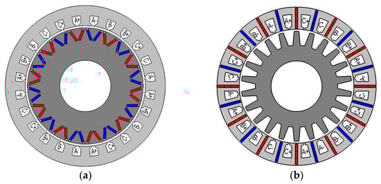
Figure 1.
Sketch of the machine geometry: (a) interior permanent magnet synchronous generator (IPMSG); (b) permanent magnet flux-switching generator (PMFSG).
The supply frequency is fe,IPM = p × fm/60 Hz, where fm is the mechanical rotational speed, rpm. The stator of the PMFSG has 24 teeth with half-open slots, while the magnets are inserted in each stator tooth. The magnets located in the nearest slots are magnetized in opposite directions. The stator integrity is ensured by thin ribs at the outer and inner stator surfaces. Each second stator tooth is wound. Each magnet is divided into three insulated parts to reduce the eddy currents losses in the magnets. The toothed rotor is made of electrical steel laminations and has no magnets and winding. The supply frequency fe,FSM = Zr × fm/60, where Zr = 22 is the number of rotor teeth. Consequently, the required supply frequency is 2.2 times higher for the PMFSG than for the IPMSG at the same mechanical rotational frequency.
3. Two-Mode Substituting Load Profile of Wind Turbine
In this study, minimizing the loss averaged over the load profile of the wind generator is one of the objectives of the optimization because it results in a higher efficiency machine over the entire load range. In order to reduce the calculation time of the losses without considerable effect on the accuracy, this study applied an approach for designing a gearless generator for wind turbines using a two-modes substituting load profile. This approach has been described in detail while used for the design of a PMFSG with ferrite magnets [7,23].
The authors considered PMFSGs and IPMSGs designed for the wind turbine that operated at the wind speed range from 4 to 12 m/s [27]. Table 1 provides the data on the rotational speed ni, mechanical power Pmech i, and torque Ti of the turbine at different operating points (modes). Data on the wind speed Vi and statistical probability of an i-th mode pi are also presented.

Table 1.
Initial nine-modes profile of the wind generator. ni: rotational speed; Pmech i: mechanical power; Ti: torque; Vi: wind speed; pi statistical probability of an i-th mode.
An annual wind speed distribution was approximated by the one-parameter Rayleigh distribution [28], while the average speed was taken as 7 m/s. As long as the considered wind speeds of the modes were integers, the probabilities of the modes were assumed to be equal to the Rayleigh distribution density at the given wind speed. The values pi were formed by normalizing the probabilities of the nine modes, in a way that they got summed up as 1. The torque provided in Table 1 was interpolated by a cubic polynomial as a function of the mechanical power Pmech using the least-squares method (“cftool”, Matlab toolbox) with the adjusted R2 equal to 0.9997 and SSE (Error Sum of Squares) equal to 0.3642 (Figure 2). The interpolated dependence is as follows:
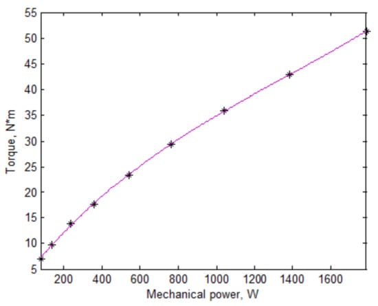
Figure 2.
Loading torque profile of the wind turbine. Individual points of the load profile from Table 1 are marked with asterisks. The polynomial interpolation dependence is shown with the solid line.
In Figure 2, the obtained relation between the torque and mechanical power is presented. This interpolated dependence allows one to consider various mode characteristics (the torque, the losses, the torque ripple, etc.) as a function of the only argument Pmech. Then, the substituting load profile was created in a way that the means were coincident with the means of the original profile [7]. Operator <…> denotes a (weighted) averaged over all points of a selected load profile. Therefore, the means of the polynomial interpolated values over the original profile and substituting load profile were coincident. Additionally, the loading mode with the highest power was included in the substituting mode. The loading mode determined the required converter power used as one of the optimization objectives. The rest of the modes of the substituting profile were characterized by two parameters: probability and mechanical power, which determined the point on the turbine’s maximum power curve (Figure 2). Generally, m-mode substituting load profile, (m − 1) modes can be adjusted, and the polynomial degree becomes 2∙(m − 1). For instance, when the values can accurately be interpolated by quadric polynomial, the two-mode substituting profile is sufficient. The substituting two-mode load profile of the wind turbine is presented in Table 2. The proposed two-mode load profile significantly decreased the computational time without considerable effect on the accuracy of calculations [7].
Table 2.
Substituting two-mode profile.
4. PMFSG and IPMSG Optimization Models
4.1. Optimization Objectives
The mathematical models of both machines, based on solving 2D magnetostatic boundary problems, were used for the optimization. To reduce the computation time, the model took into account the motors’ instantaneous symmetry and the periodicity of the electromagnetic processes. The optimization model of the PMFSG consisted of three objectives that were joined into one objective function [7]:
where K1, K2, and K3 are the optimization objectives. Particularly, K1 = < Ploss > represents the losses averaged over the substituting load profile and annual energy production. K2 is the required power of the frequency converter:
where Iampl,rated and VDC,rated are the current amplitude and the DC voltage of the frequency converter required at the rated conditions (T = 100%, n = 100%), respectively. At these conditions, K1 and K2 reach their peak. The objective K2 is coincident with the apparent power when the current and voltage are sinusoidal and symmetric. Moreover, K2 includes VDC,rated, which is the converter limitation. It is important to notice that VDC,rated should not include the losses. The reason is that if the active power decreases, K2 would be reduced and could be considered as a gain in the objective function. K3 represents the cost of magnetic material:
where lmag = R1 − R3 − 2∙Δ3 is the radial length of the magnets, hmag is their thickness, R1 is the outer stator radius; R3 is the inner stator radius; Δ3 is the thickness of the outer and inner stator ribs holding the magnets (see Figure 3) and L is the stack length. K3 is to decrease the cost of the magnets and similar to the volume, i.e., equal to the product of three dimensions of the magnets, but the magnet thickness is increased by 0.001 m (meters) in (4) to take into account that thin magnets cost more than thick ones [29].
F = K1 ∙ K22 ∙ K30.5
K2 = √3 ∙ Iampl,rated ∙ VDC,rated/2
K3 = L ∙ (hmag + 0.001 m) ∙ lmag
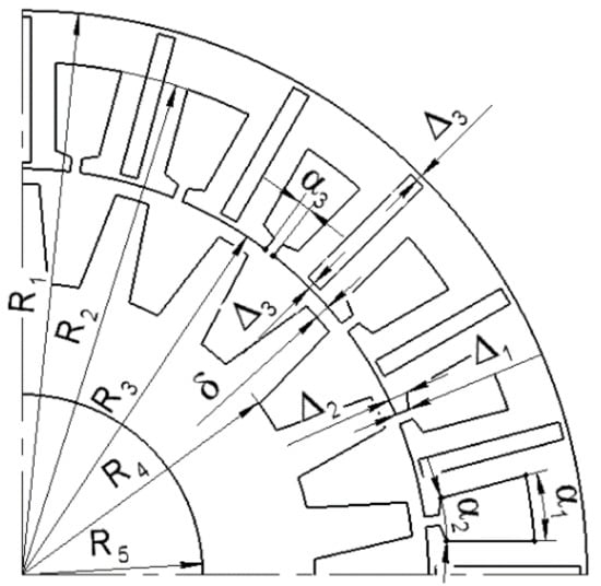
Figure 3.
PMFSG parameters.
The power of K2 and K3 in (2) represents the percentage of the decrease in K1 as valuable as the decrease in K2 and K3 by 1%. Particularly, the change in K2 by 1% is as valuable as the change in K1 by 2%, and the change in K3 by 1% is as valuable as the change in K1 by 0.5%. Basically, the higher the exponent of the objective, the more valuable the objective is.
It is worth mentioning that although the torque ripple of the initial design of the IPMSM was not very high, it was much higher than that of PMFSG. Therefore, an additional element K4 equal to the torque ripple averaged over the substituting profile was added in (2) to construct the objective function used for the IPMSM optimization:
where K4 is the relative torque ripple averaged over the substituting profile. The factors “1”, “2”, “0.5”, and “0.25” were not calculated by any formal method. The values simply indicate the approximate relative importance of each of the K1–K4 optimization objectives, according to the authors’ experience in the design of similar machines.
F = K1∙K22∙K30.5∙K40.25
It is important to highlight that functions (2) and (5) had noise due to round errors coming from FEM (Finite Element Method) calculations and differences in the grid for multiple calls of the objective function. Therefore, the Nelder–Mead method was chosen since it is able to deal with objective functions with noise [30].
The Nelder–Mead algorithm is well known [31] and is included in the basic MATLAB software package (function “fminsearch”). The unconstrained one-criterion Nelder–Mead method is applied in this work to optimize the PMFSG design. After the initial simplex was built, the Nelder–Mead algorithm as it is described in [31] was applied. The reflection, expansion, and contraction coefficients are 1, 2, and 1/2, respectively. The used generator model based on the FEM is described in [7].
4.2. Optimization Parameters of PMFSG
Figure 3 shows the main dimensions of the PMFSG. Additionally, Table 3 shows the geometric parameters fixed during optimization, while Table 4 provides the geometric parameters varied during the optimization and their initial values.
Table 3.
Fixed parameters of the PMFSG. ts: the angular tooth pitch of the stator.
Table 4.
Initial values of the PMFSG parameters varied during the optimization. tr: the angular tooth pitch of the rotor.
In order to reduce the reactive power, the current angle was varied. The current angle was supposed to be proportional to the torque. The zero current angle corresponds to the maximum torque when the current does not influence the steel saturation.
4.3. Optimization Parameters of IPMSG with V-Shaped Magnetic Poles
Figure 4 shows the main dimensions of the stator and rotor of the IPMSG. Table 5 shows the parameters fixed during the optimization and Table 6 reports the parameters varied during the optimization and their initial values. It is important to mention that during the optimization, the slot opening remained the same and was determined by the winding technology. The geometry of the rotor was created by the following procedure. Firstly, point 1 was set at the angle α in the circle with the radius R’ remoted from the outer rotor boundary. D and d2 defined the position of point 2. Point 5 was located in a distance of d5 from the outer rotor boundary and on the same radius as point 4. Segment 1–4 (the magnet thickness) was perpendicular to segment 1–2, whose length was chosen to obtain the fixed values d. Point 7 was placed at the same circle with point 5, and the angular distance between these points was fixed (see Figure 4b).
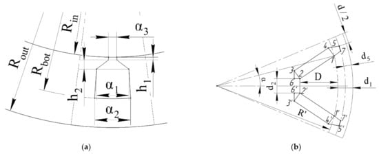
Figure 4.
IPMSG parameters: (a) Stator parameters; (b) Rotor parameters.
Table 5.
Fixed parameters of the interior permanent magnet synchronous machine (IPMSM).
Table 6.
Initial values of the IPMSM parameters varied during the optimization.
5. PMFSG and IPMSG Comparison before Optimization
The initial geometry and magnetic flux density at the rated mode of the IPMSG and PMFSG are shown in Figure 5a,b, respectively. The calculation of the cost of active materials was based on the assumption that the steel price was USD 1/kg, the copper price was USD 7/kg, and the permanent magnet price was USD 126.6/kg [29,32]. Table 7 provides the main characteristics of the PMFSG and IPMSG initial designs.
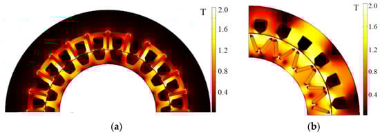
Figure 5.
Initial design and magnetic flux density at the rated mode: (a) PMFSG; (b) IPMSG.
Table 7.
Characteristics of the PMFSG and IPMSG initial designs.
6. Optimization Results and PMFSG and IPMSG Comparison after Optimization
Figure 6, Figure 7 and Figure 8 show the changes in the efficiencies, the required converter powers, and the objective function value during the process of the optimization. The left figures (a) are for flux-switching machines (FSMs). The right figures (b) are for interior permanent magnets (IPMs). Objective function (2) was used for the PMFSG optimization. Objective function (5) was used for the IPMSG optimization. It is seen that the optimization goes through the very bad solution with very high converter power and very low efficiency and objective function value. However, there are trends of the efficiency growth and the decline in the required converter power. The maximum efficiencies of both FSMs and in both modes are achieved approximately at the middle of the optimizations. These efficiencies are a little bit lower in the final optimization point because the optimization is a compromise between the optimization objectives.
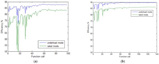
Figure 6.
The change in efficiency during optimization. (a) PMFSG; (b) IPMSG.
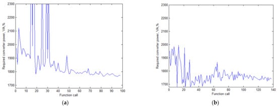
Figure 7.
The change in the required converter power during optimization. (a) PMFSG; (b) IPMSG.
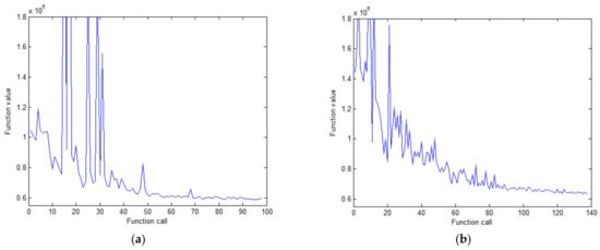
Figure 8.
The change in the objective function call during optimization. (a) PMFSG; (b) IPMSG.
The optimized designs of IPMSGs and PMFSGs and the magnetic flux density at the rated mode are shown in Figure 6a,b, respectively. The optimized values of the varied parameters are given in Table 8 and Table 9. Although the stator inner radius of the PMFSG is greater than that of the IPMSM by 19%, the moment of inertia of the active materials of the PMFSG rotor is more than thrice as low. It is because the PMFSG rotor core is thin and has thick teeth.
Table 8.
Optimized values of the varied parameters of the PMFSG.
Table 9.
Optimized values of the varied parameters of the IPMSM.
Table 10 reports the main characteristics of PMFSGs and IPMSGs after optimization. During the optimization, the torque ripple of both motors reduces significantly. The optimized values of the varied parameters are given in Table 8 and Table 9. Figure 6a presents the dependence of total losses on mechanical power for both machines in the optimized condition. Figure 6b shows the electric losses in different parts of the machines at the rated conditions. It can be clearly seen that the most considerable losses for both machines were the copper losses. At the same time, the copper losses, as well as the rotor steel losses, in the IPMSG were noticeably lower.
Table 10.
Characteristics of the optimized PMFSG and IPMSG.
What stands out in Table 8 that the average losses in the IPMSG are 1.2 times lower than in the PMFSG. The active output power of the IPMSG is higher both at the rated mode and at the low load mode of the two-point profile. Moreover, the IPMSG required a frequency converter with less power than the PMFSG. Talking about the advantages of the PMFSG, it is important to highlight that the torque ripple at the rated mode in the PMFSG was three times lower than in the IPMSG, and the mass of the magnets is lower by 1.4 times. The optimized geometry and magnetic flux density at the rated mode of the IPMSG and PMFSG are shown in Figure 9a,b, respectively.
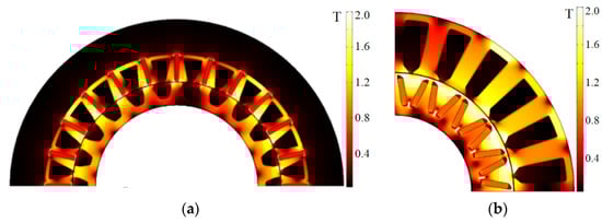
Figure 9.
Optimized design and magnetic flux density at the rated mode: (a) PMFSG; (b) IPMSG.
The losses in the PMFSG (blue asterisks) and the IPMSG (red asterisks) at nine modes of the profile presented in Table 1 are shown in Figure 10a. The losses in the PMFSG are higher than those in the IPMSG in a wide range of powers.
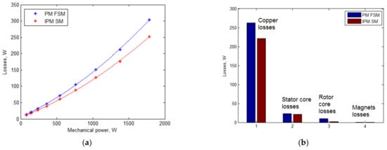
Figure 10.
Comparative dependencies: (a) dependence of total losses on mechanical power of PMFSG and IPMSG; (b) electric losses of PMFSG and IPMSG at the rated conditions.
The two-profile approach is developed for the cases when the dependence of these losses on the mechanical power can be approximated by a quadric polynomial [7]. Such approximations shown in Figure 10a with continuous lines are rather accurate (R2 = 0.9998 for both cases), which justifies the accuracy of substituting the initial nine-point profile with the two-point one. Figure 11 shows a comparison of the efficiency and torque ripple of the optimized generators at all points of the considered working profile.
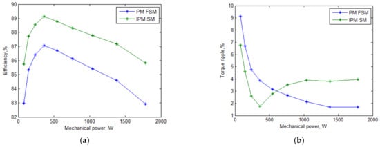
Figure 11.
Comparative dependencies on mechanical power: (a) efficiency (b) torque ripple.
The torque ripple in the IPMSG was quite low, namely, below 4%. Another revealed advantage of the PMFSG was a lower cost of rare-earth magnets. Particularly, the PMFSG required 1.4 times less rare-earth magnetic material than the IPMSG. Considering that the mining of rare-earth materials and their manufacturing have a harmful effect on the environment, this advantage of the PMFSG is highly valuable for mass production [33]. Furthermore, Table 8 shows that the demand for copper in the PMFSG was twice lower than for the IPMSG. Consequently, the cost of active materials for the PMFSG was 1.4 times lower than for the IPMSG, mainly due to the reduction in the magnets mass.
7. Conclusions
The aim of this study was to theoretically compare the PMFSG with a conventional IPMSG in a direct-driven low-power wind application. To ensure a fair comparison, both machines were first optimized using the Nelder–Mead algorithm. The optimization objective functions were selected so as to take into account the required power of frequency converter, the evaluation of the active materials cost, and losses in generators averaged over the working profile of the wind turbine. Additionally, the torque ripple was included in the optimization function of the IPMSG, since this parameter was significantly higher in the IPMSG than in the PMFSG. To reduce the computational time, the substituting profile method was applied. As a result, the strengths and weaknesses of the machines were revealed.
This study shows that the PMFSG requires 1.4 times less rare earth-earth magnet material than the IPMSG. Considering that the mining of rare-earth materials and their manufacturing have a harmful effect on the environment, this advantage of the PMFSG is highly valuable for mass production. In addition, the PMFSG torque ripple is less. However, the PMFSG requires a slightly higher power rating of the semiconductor inverter, and the average losses in the IPMSG are 1.2 times lower than in the PMFSG.
The results of this comparative study can be used by developers of direct-driven wind generators when selecting the type of electric machine suitable for a specific wind power application.
Author Contributions
Conceptual approach, V.P. and V.D.; data curation E.A. and V.K.; software V.D. and V.P.; calculations and modeling, V.P and V.D. and V.K.; writing of original draft, E.A., V.P., V.D. and V.K.; visualization, E.A., V.D. and V.K.; review and editing, E.A., V.P., V.D. and V.K. All authors have read and agreed to the published version of the manuscript.
Funding
This research received no external funding.
Informed Consent Statement
Not applicable.
Data Availability Statement
Data is contained within the article.
Acknowledgments
The authors thank the editors and reviewers for careful reading, and constructive comments.
Conflicts of Interest
The authors declare no conflict of interest.
References
- Saleh, S.; Khan, M.; Rahman, M. Steady-state performance analysis and modelling of directly driven interior permanent magnet wind generators. IET Renew. Power Gener. 2011, 5, 137. [Google Scholar] [CrossRef]
- Andriushchenko, E.; Kallaste, A.; Vaimann, T.; Rassolkin, A.; Heidari, H.; Demidova, G.L. Simulation of Wind Turbine Vibrations. In Proceedings of the 2020 27th International Workshop on Electric Drives: MPEI Department of Electric Drives 90th Anniversary (IWED), Moscow, Russia, 27–30 January 2020; pp. 1–4. [Google Scholar]
- Ahsanullah, K.; Dutta, R.; Rahman, M.F.; Dutta, R. Analysis of Low-Speed IPMMs With Distributed and Fractional Slot Concentrated Windings for Wind Energy Applications. IEEE Trans. Magn. 2017, 53, 1–10. [Google Scholar] [CrossRef]
- Chen, H.; Qu, R.; Li, J.; Li, D. Demagnetization Performance of a 7 MW Interior Permanent Magnet Wind Generator with Fractional-slot Concentrated Windings. IEEE Trans. Magn. 2015, 51, 1. [Google Scholar] [CrossRef]
- Karimpour, S.R.; Besmi, M.R.; Mirimani, S.M. Optimal design and verification of interior permanent magnet synchronous generator based on FEA and Taguchi method. Int. Trans. Electr. Energy Syst. 2020, 30, 12597. [Google Scholar] [CrossRef]
- Lehr, M.; Dietz, D.; Binder, A. Electromagnetic design of a permanent magnet Flux-Switching-Machine as a direct-driven 3 MW wind power generator. In Proceedings of the 2018 IEEE International Conference on Industrial Technology (ICIT), Lyon, France, 20–22 February 2018; pp. 383–388. [Google Scholar]
- Dmitrievskii, V.; Prakht, V.; Kazakbaev, V. Design Optimization of a Permanent-Magnet Flux-Switching Generator for Direct-Drive Wind Turbines. Energies 2019, 12, 3636. [Google Scholar] [CrossRef]
- Ditmanson, C.; Hein, P.; Kolb, S.; Molck, J.; Bernet, S. A New Modular Flux-Switching Permanent-Magnet Drive for Large Wind Turbines. IEEE Trans. Ind. Appl. 2014, 50, 3787–3794. [Google Scholar] [CrossRef]
- Su, P.; Hua, W.; Zhang, G.; Chen, Z.; Cheng, M. Analysis and evaluation of novel rotor permanent magnet flux-switching machine for EV and HEV applications. IET Electr. Power Appl. 2017, 11, 1610–1618. [Google Scholar] [CrossRef]
- Fasolo, A. Multi Polar Direct Drive Permanent Magnet Synchronous Machines for Renewable Energy. Ph.D. Thesis, University of Padova, Padova, Italy, 2013. Available online: http://paduaresearch.cab.unipd.it/5818 (accessed on 19 March 2021).
- Fasolo, A.; Alberti, L.; Bianchi, N. Performance comparison between switching-flux and IPM machine with rare earth and ferrite PMs. In Proceedings of the 2012 XXth International Conference on Electrical Machines, Marseille, France, 2–5 September 2012; pp. 731–737. [Google Scholar]
- Fasolo, A.; Alberti, L.; Bianchi, N. Performance Comparison Between Switching-Flux and IPM Machines with Rare-Earth and Ferrite PMs. IEEE Trans. Ind. Appl. 2014, 50, 3708–3716. [Google Scholar] [CrossRef]
- Howe, D.; Chen, Y.S.; Zhu, Z.Q. Online optimal flux-weakening control of permanent-magnet brushless AC drives. IEEE Trans. Ind. Appl. 2000, 36, 1661–1668. [Google Scholar] [CrossRef]
- Pellegrino, G.-M.L.; Vagati, A.; Guglielmi, P.; Boazzo, B. Performance Comparison Between Surface-Mounted and Interior PM Motor Drives for Electric Vehicle Application. IEEE Trans. Ind. Electron. 2012, 59, 803–811. [Google Scholar] [CrossRef]
- Pang, Y.; Zhu, Z.Q.; Howe, D.; Iwasaki, S.; Deodhar, R.; Pride, A. Comparative study of flux-switching and interior perma-nent magnet machines. In Proceedings of the 2007 International Conference on Electrical Machines and Systems (ICEMS), Seoul, Korea, 1–2 November 2007; pp. 757–762. Available online: https://ieeexplore.ieee.org/document/4412185 (accessed on 19 March 2021).
- Tang, Y.; Motoasca, E.; Paulides, J.J.; Lomonova, E.A. Comparison of flux-switching machines and permanent magnet synchronous machines in an in-wheel traction application. COMPEL Int. J. Comput. Math. Electr. Electron. Eng. 2012, 32, 153–165. [Google Scholar] [CrossRef]
- Thomas, A.; Zhu, Z.; Jewell, G. Comparison of flux switching and surface mounted permanent magnet generators for high-speed applications. IET Electr. Syst. Transp. 2011, 1, 111. [Google Scholar] [CrossRef]
- Isfahani, A.H.; Boroujerdi, A.H.-S.; Hasanzadeh, S. Multi-objective design optimization of a large-scale directdrive permanent magnet generator for wind energy conversion systems. Front. Energy 2014, 8, 182–191. [Google Scholar] [CrossRef]
- Ibrahim, H.A. Wind Turbines; IntechOpen: London, UK, 2011; p. 652. [Google Scholar]
- Shao, L.; Hua, W.; Soulard, J.; Zhu, Z.-Q.; Wu, Z.; Cheng, M. Electromagnetic Performance Comparison Between 12-Phase Switched Flux and Surface-Mounted PM Machines for Direct-Drive Wind Power Generation. IEEE Trans. Ind. Appl. 2020, 56, 1408–1422. [Google Scholar] [CrossRef]
- Ojeda, J.; Simoes, M.G.; Li, G.; Gabsi, M. Design of a Flux-Switching Electrical Generator for Wind Turbine Systems. IEEE Trans. Ind. Appl. 2012, 48, 1808–1816. [Google Scholar] [CrossRef]
- Meo, S.; Zohoori, A.; Vahedi, A. Optimal design of permanent magnet flux switching generator for wind applications via artificial neural network and multi-objective particle swarm optimization hybrid approach. Energy Convers. Manag. 2016, 110, 230–239. [Google Scholar] [CrossRef]
- Prakht, V.; Dmitrievskii, V.; Kazakbaev, V. Optimal Design of Gearless Flux-Switching Generator with Ferrite Permanent Magnets. Mathematics 2020, 8, 206. [Google Scholar] [CrossRef]
- Prakht, V.; Dmitrievskii, V.; Kazakbaev, V.; Ibrahim, M.N. Comparison between rare-earth and ferrite permanent magnet flux-switching generators for gearless wind turbines. Energy Rep. 2020, 6, 1365–1369. [Google Scholar] [CrossRef]
- Cupertino, F.; Pellegrino, G.; Gerada, C. Design of Synchronous Reluctance Motors with Multiobjective Optimization Algorithms. IEEE Trans. Ind. Appl. 2014, 50, 3617–3627. [Google Scholar] [CrossRef]
- Krasopoulos, C.T.; Beniakar, M.E.; Kladas, A.G. Robust Optimization of High Speed PM Motor Design. IEEE Trans. Magn. 2017, 53, 1. [Google Scholar] [CrossRef]
- Anandavel, P.; Rajambal, K.; Chellamuthu, C. Power Optimization in a Grid-Connected Wind Energy Conversion System. In Proceedings of the 2005 International Conference on Power Electronics and Drives Systems, Kuala Lumpur, Malaysia, 28 November–1 December 2005; pp. 1617–1621. [Google Scholar]
- Pishgar-Komleh, S.; Keyhani, A.; Sefeedpari, P. Wind speed and power density analysis based on Weibull and Rayleigh distributions (a case study: Firouzkooh county of Iran). Renew. Sustain. Energy Rev. 2015, 42, 313–322. [Google Scholar] [CrossRef]
- ChenYang NdFeB Magnets. Price List of Standard Block Magnets. Available online: http://www.ndfebmagnets.de/CY-PriceList-NdFeB-Block.pdf (accessed on 19 March 2021).
- Audet, C.; Tribes, C. Mesh-based Nelder–Mead algorithm for inequality constrained optimization. Comput. Optim. Appl. 2018, 71, 331–352. [Google Scholar] [CrossRef]
- Nelder, J.A.; Mead, R. A Simplex Method for Function Minimization. Comput. J. 1965, 7, 308–313. [Google Scholar] [CrossRef]
- Prakht, V.; Dmitrievskii, V.; Kazakbaev, V.; Oshurbekov, S. Comparison of High-Speed Single-Phase Flux Reversal Motor and Hybrid Switched Reluctance Motor. In Proceedings of the 2019 20th International Symposium on Power Electronics (Ee), Novi Sad, Serbia, 21–26 October 2019; pp. 1–5. [Google Scholar]
- De Lima, I.B.; Filho, W.L. Rare Earths Industry; Elsevier BV: Amsterdam, The Netherlands, 2016; p. 434. [Google Scholar]


Publisher’s Note: MDPI stays neutral with regard to jurisdictional claims in published maps and institutional affiliations. |
© 2021 by the authors. Licensee MDPI, Basel, Switzerland. This article is an open access article distributed under the terms and conditions of the Creative Commons Attribution (CC BY) license (http://creativecommons.org/licenses/by/4.0/).