


Abstract
This paper presents a nonlinear vertical dynamic model of an electromagnetic suspension (EMS) system in maglev trains regulated by a dual nonlinear saturation controller (DNSC) under simultaneous resonance (). The governing nonlinear differential equations of the system are addressed analytically utilizing the multiple time-scale technique (MTST), concentrating on resonance situations obtained from first-order approximations. The suggested controller incorporates two nonlinear saturation functions in the feedback and feedforward paths to improve system stability, decrease vibration levels, and enhance passenger comfort amidst external disturbances and parameter changes. The dynamic bifurcations caused by DNSC parameters are examined through phase portraits and time history diagrams. The goal of control is to minimize vibration amplitude through the implementation of a dual nonlinear saturation control law based on displacement and velocity feedback signals. A comparative analysis is performed on different controllers such as integral resonance control (IRC), positive position feedback (PPF), nonlinear integrated PPF (NIPPF), proportional integral derivative (PID), and DNSC to determine the best approach for vibration reduction in maglev trains. DNSC serves as an effective control approach designed to minimize vibrations and enhance the stability of suspension systems in maglev trains. Stability evaluation under concurrent resonance is conducted utilizing the Routh–Hurwitz criterion. MATLAB 18.2 numerical simulations (fourth-order Runge–Kutta) are employed to analyze time-history responses, the effects of system parameters, and the performance of controllers. The evaluation of all the derived solutions was conducted to verify the findings. Additionally, quadratic velocity feedback leads to intricate bifurcation dynamics. In the time domain, higher displacement and quadratic velocity feedback may destabilize the system, leading to shifts between periodic and chaotic movements. These results emphasize the substantial impact of DNSC on the dynamic performance of electromagnetic suspension systems. Frequency response, bifurcation, and time-domain evaluations demonstrate that the DNSC successfully reduces nonlinear oscillations and chaotic dynamics in the EMS system while attaining enhanced transient performance and resilience.
Keywords:
maglev train; electromagnetic suspension; DNSC; vibration suppression; perturbation; stability; bifurcation; chaos control MSC:
65P20; 74H10; 74H45
1. Introduction
Electromagnetic suspension (EMS) technology forms the foundation of modern maglev train systems, enabling contactless levitation, high-speed travel, and enhanced ride quality. However, the intrinsic open-loop instability of EMS actuators, strong electromagnetic–mechanical coupling, and sensitivity to external disturbances necessitate advanced control strategies to ensure safe and stable levitation. Recent surveys and experimental assessments confirm that stability enhancement and vibration reduction remain central challenges for EMS-type maglev vehicles, despite considerable progress in actuator design and controller development [1]. In recent years, multiple control approaches have been proposed to enhance the performance of EMS suspension systems, including linear PID-based strategies, state-observer-based techniques, and nonlinear robust controllers. Feedback linearization combined with extended state observers (ESO) has been used to address coupling between suspension modules and compensate for severe disturbances, demonstrating improved robustness under parametric uncertainty [2]. Furthermore, new vibration suppression methodologies have been developed to handle mechanical coupling among adjacent suspension points, employing geometric transformation and decoupling techniques to improve dynamic stability during operation [3]. Data-driven evaluation frameworks have also emerged, providing performance metrics for ride comfort and suspension stability using real-time operational data [4]. Despite these advancements, several limitations persist. Existing EMS studies generally focus on improving suspension robustness under standard operating conditions or treating specific nonlinearities in isolation—for example, improving levitation height tracking, mitigating coupling effects, or increasing disturbance rejection capability. However, nonlinear resonance phenomena, especially under simultaneous resonance, remain underexplored. These multi-frequency interactions can significantly amplify vertical oscillations, compromise ride comfort, and even destabilize the levitation gap. While nonlinear dynamic behaviors of magneto-mechanical systems under combined excitations have been studied in related mechanical systems [5], EMS-specific resonance interactions, particularly simultaneous resonance, have not been systematically analyzed. Frequency-modified analytical techniques have recently been refined for nonlinear oscillators, such as the He–Mohammadian frequency correction method, which enhances the accuracy of first-order approximations and captures nonlinear coupling effects with improved fidelity [6]. However, these analytical tools have not been extended to analyze nonlinear EMS suspension systems under concurrent resonance conditions, leaving a research gap in predictive modeling and resonance-aware control [7]. From the control perspective, several advanced controllers have been proposed for nonlinear vibration suppression, including enhanced positive position feedback (PPF) [8], improved integral resonance control (IRC) under parameter variation [9], and nonlinear integrated PPF (NIPPF) with saturation constraints [10]. Robust PID controllers with nonlinear damping compensation have also shown improved transient performance in magnetic suspension systems [11]. More recently, adaptive ESO-based strategies and hybrid saturation damping controllers have demonstrated enhanced robustness to model uncertainties and disturbances [12,13]. While these methods address certain nonlinearities or disturbances, none provide a structured mechanism for suppressing high-amplitude oscillations arising from concurrent resonance or for preventing actuator overdrive during nonlinear dynamic excursions. Moreover, quadratic velocity feedback—which appears in many nonlinear control laws—can induce complex bifurcation patterns and chaotic motion when interacting with structural or electromagnetic nonlinearities, as demonstrated in various electromechanical systems [14]. These dynamics have important implications for EMS stability but remain insufficiently investigated in existing literature. Nonetheless, PID control faces challenges in robustness when subjected to significant disturbances and nonlinearity, particularly during instances of actuator saturation [15,16]. To improve strength and flexibility, nonlinear and intelligent controllers like sliding mode control (SMC), adaptive control, backstepping, and model predictive control (MPC) have been implemented [17,18,19,20]. These techniques enhance performance but typically necessitate intricate modeling, increased computational power, or thorough parameter adjustments [21].
Magnetic levitation (maglev) technologies have emerged as a central theme in high-speed transit because of their frictionless functionality, minimal upkeep, and energy effectiveness. Among the different maglev designs, electromagnetic suspension (EMS) systems are commonly used due to their straightforward structure and quick response. Nonetheless, the effectiveness of EMS systems is very responsive to vibration disruptions, which may arise from track inconsistencies, vehicle–guideway interactions, or nonlinear electromagnetic forces [22]. The behavior of EMS systems is inherently nonlinear and frequently influenced by interactions between suspension and guidance. Moreover, time lags in control loops resulting from sensor processing, actuator behavior, and communication delays add extra complexity. If not properly considered, these delays may result in bifurcation, resonance amplification, and potentially chaotic motion [23,24]. Zhang et al. [25] demonstrated that time-lagged feedback in maglev systems can induce Hopf bifurcations, leading to unstable periodic oscillations. Simultaneously, vibration reduction in maglev systems has attracted significant research focus. Flexibly designed tracks and vehicles create resonant modes that may lead to oscillations and discomfort for passengers [26]. To eliminate these vibrations, Positive Position Feedback (PPF) controllers have been successfully utilized [27,28]. PPF controllers incorporate a resonant filter adjusted to the vibration frequency, enhancing damping while maintaining stability [29]. Additionally, Nonlinear Integral Positive Position Feedback (NIPPF) builds upon PPF by incorporating nonlinear integral components, improving low-frequency disturbance rejection and steady-state precision [30,31]. In the same way, Integral Resonant Controllers (IRC) are employed to manage lightly damped resonant dynamics through the integration of an integral action with resonant filters [32]. These controllers show effective vibration reduction but face limitations when addressing significant nonlinearities or actuator restrictions. A significant practical constraint in maglev control is actuator saturation. Notably, Zheng et al. [33] propose a systematic methodology to improve the safety margin and vibration stability of high-temperature superconducting (HTS) maglev transport systems by addressing passive levitation instability challenges inherent to HTS pinning maglev technology, with an emphasis on system-level safety and robustness under external disturbances. In a related study, Zheng et al. [34] introduce a novel HTS maglev configuration employing a double-sided homopolar linear synchronous motor (H-LSM) to enhance propulsion performance and electro–mechanical coupling characteristics, demonstrating improved macroscopic performance metrics compared with traditional PM-LSM schemes. While both studies significantly contribute to the design and dynamic characterization of HTS maglev infrastructures, they primarily focus on propulsion performance and system structural dynamics. By contrast, the present work specifically targets active vibration suppression and resonance stabilization in electromagnetic suspension dynamics through advanced control methodology. The DNSC framework we propose goes beyond structural and propulsion optimization by introducing a robust control design that manages bifurcation-induced instabilities and reshapes the forced frequency response of the suspension itself, aspects not directly addressed in these HTS maglev publications. This delineation clarifies the technical novelty and domain focus of our contribution relative to recent HTS maglev research.
While nonlinear resonance, particularly simultaneous primary and internal resonances, has been identified as an underexplored yet critical issue in EMS systems, most existing controllers (e.g., PPF, NIPPF, IRC, PID) address only a single dominant nonlinear effect. Such controllers are not designed to manage the multi-path nonlinear energy exchanges that arise under simultaneous resonance conditions. Although saturation-based approaches have shown promise in mitigating isolated nonlinear modes, prior work has used only one saturation mechanism, which limits control authority when multiple resonant interactions occur concurrently. To bridge this gap, the present work introduces a Dual Nonlinear Saturation Controller (DNSC) that integrates two coordinated saturation functions, each targeting a different dynamic pathway. This dual structure is specifically formulated to suppress both the primary and coupled resonant responses, thereby providing a level of robustness and damping performance that single-saturation or conventional nonlinear controllers cannot achieve. This constitutes the core novelty of the DNSC and directly addresses the unmet needs identified in the existing literature.
To overcome these constraints, this study formulates a nonlinear vertical dynamic model for an electromagnetic suspension (EMS) system in maglev trains, regulated by DNSC during concurrent resonance scenarios. The DNSC strategy incorporates two nonlinear saturation functions that operate on both displacement and velocity feedback signals. This setup allows limited control action, avoids actuator saturation, and improves system robustness to significant deviations and parameter uncertainties. The DNSC effectively minimizes excessive oscillations while ensuring stability and energy efficiency by integrating nonlinear saturation characteristics in both control pathways. The governing nonlinear differential equations of the EMS system are solved analytically through the Multiple Time-Scale Technique (MTST), emphasizing first-order approximations during primary and simultaneous resonance. The rationale for employing DNSC is compelling: NSC can limit the control action to safe, bounded levels (helping with actuator saturation or safety constraints), while allowing nonlinear feedback paths that respond to large deviations. When integrated with position and velocity, DNSC shows potential for ensuring stability even in difficult conditions (significant excitation, high delays, and intense nonlinearity). The dynamic bifurcation effects caused by DNSC parameters are examined through phase portraits to define shifts among stable, periodic, and chaotic states. Additionally, resonance stability analysis is performed using the Routh–Hurwitz criterion, yielding insights into the stabilizing effects of DNSC on the system’s dynamic characteristics. Simulation research shows that DNSC obtains quicker settling time, less overshoot, and diminished control energy when compared to PID, IRC, PPF, and NIPPF controllers. MATLAB numerical simulations are performed to examine time-domain responses, effects of system parameters, and controller effectiveness. The findings indicate that the DNSC offers better vibration suppression, greater stability margins, and increased robustness than traditional control techniques. Increased feedback in displacement and velocity is noted to destabilize the system, leading to shifts from periodic to chaotic behavior, while variations in delay and excitation frequency modify the attraction basins. The remaining sections of this paper are organized as outlined below. Section 2 outlines the mathematical modeling of the levitation system in maglev technology. Section 3 outlines the designs of controllers, such as PID, IRC, PPF, NIPPF, and the suggested DNSC. Section 4 presents a comparison of simulation outcomes and an assessment of performance. Section 5 addresses considerations for implementation, while Section 6 wraps up the paper with comments on prospects for future research.
1.1. Novelty and Contributions
To address the aforementioned research gaps, this work presents a nonlinear vertical dynamic model of an electromagnetic suspension (EMS) system regulated by a dual nonlinear saturation controller (DNSC) under simultaneous resonance conditions. The main contributions of this study can be summarized as follows:
- Nonlinear EMS modeling under simultaneous resonance:
A nonlinear vertical dynamic model of the EMS system is formulated considering multi-frequency excitation and concurrent resonance interactions—an area not addressed in recent EMS control literature [1,2,3,4].
- 2.
- Dual nonlinear saturation controller (DNSC):
A novel controller incorporating two saturation nonlinearities in both feedback and feedforward pathways is proposed. This dual-path structure enhances robustness, avoids actuator overdrive, and effectively suppresses large-amplitude resonant oscillations compared with IRC, PPF, NIPPF, and PID controllers [8,9,10,11].
- 3.
- Analytical resonance investigation using MTST:
The multiple time-scale technique (MTST), supplemented with the He–Mohammadian frequency correction method [5], is applied to derive analytical solutions under concurrent resonance. This analytical treatment offers insights unavailable in observer-based or purely numerical EMS control approaches.
- 4.
- Comprehensive comparison with advanced controllers:
DNSC performance is compared with IRC, PPF, NIPPF, and PID through MATLAB simulations using the fourth-order Runge–Kutta method. Results show superior resonance suppression, enhanced transient performance, and improved robustness.
- 5.
- Bifurcation and chaotic dynamics analysis:
The nonlinear effects of quadratic velocity feedback and saturation nonlinearities are shown to induce periodic–chaotic transitions under certain parameter ranges, extending prior research on nonlinear electromechanical systems [14].
- 6.
- Unified frequency–time–bifurcation evaluation:
A multi-domain evaluation approach is presented, integrating frequency response curves, bifurcation diagrams, and time-domain simulations to provide a holistic assessment of EMS dynamic behavior—surpassing the analytical scope of recent EMS studies [1,2,3,4,12,13].
1.2. Actual Contribution Significance of the Work
The contribution of this work extends well beyond combining existing control techniques. First, the paper introduces a new dual nonlinear saturation controller (DNSC) specifically designed for EMS systems under simultaneous primary and parametric resonance, a condition not addressed in prior studies. This dual-saturation structure fundamentally alters the nonlinear energy flow in the suspension and provides vibration suppression without requiring high gains, representing a novel control architecture in maglev applications.
Second, the work provides the first analytical treatment of DNSC-regulated EMS dynamics using the Multiple Time-Scale Technique, yielding slow-flow equations and stability boundaries that offer insights unavailable in existing numerical-only studies. These analytical results uncover previously unreported nonlinear behaviors, including bifurcation transitions induced by quadratic velocity feedback.
Third, a comprehensive and fair comparison is conducted against IRC, PPF, NIPPF, and PID controllers under identical resonance conditions. The findings consistently show that DNSC achieves superior vibration attenuation, improved transient performance, and enhanced robustness to disturbances and parameter variations.
For these reasons, the work represents a genuine and original contribution both in nonlinear control methodology and EMS dynamic analysis, and provides practical engineering value for the design of stable, high-performance maglev suspension systems.
The key contribution of this work lies in the development of a dual nonlinear saturation controller (DNSC), in which two independently tuned saturation functions are placed in the feedback and feedforward paths. This dual structure overcomes the inherent limitations of the conventional single-NSC approach by decoupling stabilization and performance shaping, thereby enabling more effective resonance suppression and improved stability characteristics in the EMS system.
2. System Modeling Equations with DNSC
2.1. Derivation of the Current Model Equations
The high-speed maglev train adjusts the levitation gap of the suspension electromagnets in real time through a feedback control system in the vertical direction, while in the horizontal direction, it maintains running stability by controlling the guidance electromagnets to prevent lateral deviation from the track, as shown in Figure 1 [35]. The electromagnetic suspension system of a maglev train is an open-loop unstable system that requires active control to ensure stable operation. As shown in Figure 2, a widely adopted proportional-derivative (PD) control strategy is employed in practice to regulate the coil current, using displacement and velocity as feedback variables. In practical maglev control systems, displacement and velocity feedback signals typically originate from different measurement and processing pathways. Displacement can be directly obtained using sensors such as laser displacement sensors or eddy current probes, where signal acquisition and transmission inherently introduce a relatively small delay. In contrast, velocity signals are often derived through numerical differentiation of displacement data, which requires additional computation and filtering, thus introducing further delay. Moreover, differences in sampling frequencies across signal channels can also contribute to distinct feedback delays [36]. Therefore, the control law under displacement–velocity dual time-delay feedback can be expressed as follows:
Figure 1.
Schematic illustration of unilateral suspension and guidance in a maglev train.
Figure 2.
Schematic illustration of the feedback control system for suspension module with control current.
When a high-speed maglev train undergoes small vertical vibrations, it is also influenced by the guidance electromagnetic force [37]. Therefore, the vertical component of the guidance force is modeled as an equivalent stiffness and equivalent damping , as illustrated in Figure 3a. The calculation method for the equivalent stiffness and damping is illustrated in Figure 3b. The equivalent stiffness corresponds to the geometrically nonlinear stiffness shown in Figure 3a, where the total elongation of the spring is denoted by b, the incremental elongation by , and the deflection angle by . According to the diagram, the relationship between the spring restoring force and the elongation can be expressed as:
Figure 3.
Schematic diagram of equivalent stiffness and damping of the guidance electromagnetic force (a) and Calculation of equivalent force (b).
Based on the geometric relationship, Equation (3) can be expressed as:
Substituting Equation (3) into Equation (2) yields:
Since the geometrically nonlinear term in Equation (4) cannot be integrated analytically, a Taylor expansion is performed at z = 0, yielding:
By neglecting higher-order terms, the geometrically nonlinear stiffness is obtained as:
The equivalent damping corresponds to the geometrically nonlinear damping, as shown in Figure 3b, and its calculation follows a similar approach to that of the geometrically nonlinear stiffness. The velocity component in the damping direction is given by , and according to the definition:
The damping term is given by:
The equation of motion for the suspension–guidance coupled electromagnetic system under harmonic excitation is thus given by:
Considering only the relative motion between the electromagnetic module and the track, while neglecting the elastic vibration or dynamic deformation of the track, as well as the effects of core magnetic circuit voltage drop and magnetic leakage, the relationship between the levitation electromagnetic force and the levitation gap is given by:
where, represent the air permeability, number of coil turns of the electromagnetic module, effective pole face area, coil current, gap variation caused by external disturbances, rated current at the equilibrium position, and rated gap at the equilibrium position, respectively.
As shown in Equation (10), the electromagnetic force is an inverse-square function of the gap with respect to the current, indicating strong nonlinearity. In practice, fluctuations in electromagnetic suspension are relatively small; therefore, a Taylor series expansion of the electromagnetic force is performed about the equilibrium point .
Substituting the control current into Equation (11), and for computational convenience, neglecting higher-order terms while retaining only the odd-order terms to represent the nonlinear electromagnetic force, we obtain:
Assuming no fluctuation at the equilibrium point, the electromagnetic force satisfies , and the corresponding equilibrium current is given by:
The original Equation (9) then becomes Equation (13).
To analyze the asymptotic behavior of Equation (13) near the threshold, the method of multiple scales is introduced by Ref. [38]. It is assumed that there are two dominant time scales near the threshold: fast oscillations evolving on the first-order time scale , and a slower evolution on the time scale , where is a small parameter. Accordingly, the time-delay terms in system (13) can be represented as:
First, assume the solution takes the form:
The time-delay term is considered as:
Due to the small magnitude of the time delay, let
Thus, the time-delay terms , in the system can be rewritten as:
Substituting Equation (17a) and (17b) into Equation (13) and rearranging terms yields [39]:
where,
2.2. Classification of the Model Equations with DNSC
In our formulation, the perturbation parameter ε is not introduced for mathematical convenience but is defined based on the relative magnitude of the nonlinear electromagnetic terms compared with the dominant linear stiffness and damping components of the EMS system. The admissible range of the perturbation parameter ε is not chosen for mathematical convenience; it is directly supported by the physical characteristics of the EMS system. Using measured and documented EMS parameters, the nonlinear-to-linear stiffness ratio, damping ratio, and forcing ratio fall within 0.01–0.1, which naturally defines the perturbation magnitude. Numerical simulations further confirm that first-order MTST predictions remain accurate within this interval. This range also aligns with values reported in experimental EMS studies in the literature. For the analytical MTST derivations, we restrict the analysis to ε ≤ 0.15, corresponding to the weak-to-moderate nonlinear regime in which first-order MTST remains valid. A small perturbation parameter is introduced into Equation (18) to indicate that the modal damping, nonlinear stiffness, cubic nonlinear coupling term, and harmonic excitation force are all of comparatively small magnitude. Accordingly, Equation (18) is modified by embedding the DNSC strategy, resulting in the following system:
where and are linear damping coefficients of the main system and DNSC, denotes the forcing amplitude, indicates the frequency of the system, and are natural frequencies of the main system and DNSC, and are nonlinear factors of the main system, is the nonlinear coefficient of DNSC, is control signal gain, is feedback signal gain, respectively, is the internal controller state representing the dynamic component of the DNSC compensator, and is the small perturbation parameter used to scale the weak nonlinearities and excitation terms, .
These are two coupled second-order nonlinear ODEs: the first (20a) is the plant mechanical mode (state ), the second (20b) is the controller state dynamics (state ) that are intentionally dynamic and coupled to the plant. Together, Equations (20a) and (20b) describe the coupled dynamics of the primary nonlinear EMS mode and the DNSC compensator, where the controller state provides an additional dynamic pathway that enables dual nonlinear saturation and enhanced suppression of resonant responses.
Term-by-term physical/control interpretation
Equation (20a)—plant :
: Inertial acceleration of the plant coordinate.
: Small (modal) linear damping.
: Linear restoring stiffness (natural frequency ).
: Nonlinear term.
: Nonlinear inertial/coupling term (state-dependent effective mass).
: Cubic/quadratic coupling between velocity and displacement (nonlinear stiffness/damping coupling).
: Higher-order (quintic) stiffness nonlinearity—strong nonlinear stiffness at large amplitudes.
Right-hand side: is an external harmonic excitation.
is the control forcing applied to the plant input. Note, it enters as (nonlinear mapping of controller state to plant input).
Equation (20b)—controller state :
: Controller internal acceleration (i.e., the controller is implemented as a second-order dynamical system).
: Small damping in controller dynamics.
: Controller’s internal stiffness/oscillator term.
: Nonlinear term inside controller (makes controller dynamics nonlinear).
Right-hand side: , this is the plant → controller coupling: the controller dynamics receive feedback proportional to . This is a multiplicative coupling rather than a simple proportional feedback.
- (A)
- Definition of the controller state
In the DNSC framework, the variable is the internal dynamic state of the controller, not a physical plant variable. It is an auxiliary second-order dynamic subsystem whose evolution is governed by Equation (20b):
Thus:
- is generated internally by the controller.
- The controller receives the plant displacement as feedback.
- The output of the controller is not itself, but a nonlinear transformed signal .
- (B)
- Why this structure is called “dual nonlinear saturation”?
The DNSC controller contains two independent nonlinear limiting (“saturation”) mechanisms, hence the term dual saturation:
- (1)
- Internal nonlinear saturation inside the controller dynamics (first saturation)
The nonlinear term acts as a self-limiting amplitude regulation term inside Equation (20b).
For large or , this term grows rapidly and reduces the net energy of the controller state, thereby preventing unbounded growth. This acts mathematically as a dynamic saturation mechanism.
- (2)
- Nonlinear output saturation at the plant input (second saturation)
The control signal enters the plant through the nonlinear mapping in Equation (20a). The squaring operation enforces a bounded, always-positive control action, which grows sub- linearly in practice and effectively saturates the control effort. Specifically, the map is a static saturation nonlinearity, as it compresses negative values and limits the controller from driving the plant with oscillatory or sign-changing forces.
Together, these two nonlinearities constitute the DNSC
First saturation: nonlinear internal dynamics of .
Second saturation: nonlinear output mapping .
This dual structure provides amplitude limiting, robustness, and efficient nonlinear energy transfer from the plant to the controller.
- (C)
- How Equations (20a) and (20b) form a closed-loop control system
Plant (mechanical mode)—Equation (20a)
The plant receives two inputs: external excitation and nonlinear control signal
Controller (DNSC subsystem)—Equation (20b)
The controller receives the measured displacement as feedback and shapes its response through nonlinear dynamics.
Thus, the loop is:
The DNSC architecture consists of two dynamically and nonlinearly coupled subsystems: the plant dynamics governed by Equation (20a) and the controller dynamics governed by Equation (20b). The plant displacement is measured and supplied as feedback to the controller block, in which the internal state evolves according to a nonlinear second-order oscillator that includes the amplitude-limiting term . This nonlinear internal mechanism forms the first saturation stage of the DNSC. The controller output is then passed through a nonlinear static map , which provides the second saturation stage by shaping and limiting the control effort. The resulting control signal is combined with the external harmonic excitation and applied to the plant. This closed-loop structure enables nonlinear energy exchange between and produces the dual-saturation effect characteristic of the DNSC technique.
2.3. Mathematical Analysis via MTST
Because the EMS operates under double resonance with strong nonlinear coupling, a first-order multiple-time-scale (MTST) approximation provides useful qualitative insight but is not expected to be quantitatively exact across the whole parameter range. We therefore (i) restrict the analytical predictions to the small-amplitude/detuning window where the perturbation parameter ε satisfies , (ii) validate the first-order amplitude/phase predictions against direct numerical time-integration and show quantitative error metrics, and (iii) carry the MTST expansion to O(ε2) to obtain nonlinear detuning corrections and higher-order coupling terms that materially affect resonance peaks and stability boundaries. This combined approach ensures the analytical results are both physically interpretable and quantitatively reliable in the regimes reported.
To obtain an approximate analytical solution of Equation (20) using the MTST [40,41,42], assume the solution takes the form:
The time-related derivatives are provided by:
where . and remain the fast and slow time scales, respectively.
Using Equation (22), we can substitute Equation (21) in Equation (20), and compare the coefficients of equivalent power of on both sides to acquire:
The following formula provides the solution to Equation (23):
where and indicate a complex function that has been verified by removing small-divisor and secular terms from the first approximations. It also cc shows the complex conjugates of the terms that came before it. When Equation (25) is substituted in Equation (24), and the secular terms are eliminated, the specific solutions of Equation (24) are:
where the overbar indicates the complex conjugate function. The possible resonance cases at Equation (9) are: primary resonance (), internal resonance (), and simultaneous resonance () that is the worst one. Therefore, this case is investigated by introducing the two parameters and to designate quantitatively the nearness of the and to as following:
By inserting Equation (27) connected to the small-divisor and secular terms from Equation (24), we obtain the subsequent conditions for solvability:
For analyzing Equation (28), we rewrite and in polar form as follows:
where and are the steady-state amplitudes of the system and , are the phases of the two motions. Applying Equation (29) to Equation (28) and sorting out the real and imaginary parts, then:
where . Equations (30) and (31) form the system amplitude-phase modulating equations.
3. Stability Analysis
At steady state, the variations of amplitudes and phases of the system are zero. So the algebraic equations that govern the steady state vibrations of the considered structure can be found from Equations (30) and (31) by setting , this yield
From Equations (32) and (33) we have the following:
(i) (ii) and (iii) .
In support of the helpful case (iii), Squaring Equation (32), count the squared results together, similarly, do the same for Equation (33), next, contain the successive frequency response equations:
To perform stability criteria, we assume and are the solutions of Equations (33) and (34), and to observe the performance of small perturbations , and from the steady- state solution , and , we let
Substituting Equation (36) into Equations (30) and (31) and expanding for little parameters and to carry on only linear terms. We compact the linear system that is similar to the Equations (30) and (31) at the equilibrium point ():
Wherever the matrix above is the Jacobian matrix of the system, its coefficients are organized in the Appendix A. The following eigenvalue equations can be obtained:
Expanding the determinant at (38) yields
where is the eigenvalue of the matrix, , , , and are the coefficients of Equation (39), shown in the Appendix A. By using the Routh–Hurwitz criterion for stability, the necessary and sufficient conditions for a stable solution are:
4. Numerical Outcome
4.1. Block Control Diagrams of Maglev System with Various Control Techniques
Figure 4 depicts the control architecture and signal processing of the maglev system. The control loop consists of sensing, data transformation, signal analysis, and actuation components that function together to ensure system stability and mitigate vibrations in dynamic environments. The system starts with sensors that constantly monitor essential physical parameters, including current, position (gap), and acceleration of the levitating vehicle. These analog signals are initially routed through a signal filtering stage to remove high-frequency noise and interference. The signals that have been filtered are subsequently handled by signal conditioning circuits to confirm they fall within the operational range of the data acquisition system. Subsequently, the conditioned signals are transformed from analog to digital format through a D/A (Analog-to-Digital) converter and transmitted to the controller unit. The controller, configurable with different control algorithms (e.g., DNSC, IRC, PID, PPF, NIPPF), investigates the input data to determine the necessary corrective action to sustain levitation stability. The controller connects with a vehicle monitoring system for instantaneous diagnostics and data logging. The control signal produced by the controller is subsequently transformed back into analog form utilizing a D/A (Digital-to-Analog) converter. Subsequently, it experiences signal conditioning to conform to the specifications needed by the power electronics module. The last activation signal is transmitted to a chopper, which regulates the power supplied to the maglev system actuators to modify the electromagnetic force as needed. This closed-loop system allows for real-time adjustment of the air gap and suppression of vibration in response to changing dynamic conditions. Incorporating high-fidelity signal processing and control pathways guarantees precise feedback, minimal latency, and high responsiveness essential for functioning in near-resonant and nonlinear conditions. The control system design of the maglev system functions as a closed-loop feedback system to ensure stable levitation and accurate positioning. Sensor data, comprising current, position, and acceleration, is initially filtered and conditioned prior to being digitized by an A/D converter. The controller processes this digital input, computes the required control actions, and supplies data for monitoring the vehicle. The controller’s output is subsequently transformed back into an analog signal through a D/A converter, refined, and dispatched to a chopper that manages power to the maglev actuators. The actuators modify the magnetic fields as needed, while the sensors continuously observe the updated system state, finalizing the feedback loop for instantaneous control. The system evaluates the input reference against the measured output to produce an error signal, which the controller (DNSC) processes. The controller modifies the maglev train’s actuators according to this error, and the output of the system is constantly observed to ensure optimal performance through feedback, as shown in Figure 5.
Figure 4.
Overall structural block diagram of embedded control system for maglev train.
Figure 5.
Graphic design of the feedback control system (DNSC) for a maglev train.
All evaluations in this study are based solely on numerical simulations of the nonlinear EMS model using a fourth-order Runge–Kutta scheme. Figure 6 illustrates the conceptual signal flow and controller integration, but does not represent a physical experimental setup. Therefore, the results presented in this section constitute simulation-based validation of the proposed DNSC approach.
Figure 6.
Conceptual implementation diagram of the DNSC-based maglev control architecture.
4.2. Comparison Between Different Control Techniques to Investigate Control of This Study
This section provides the time-domain evaluation of the electromagnetic suspension (EMS) system under different resonance scenarios to assess the effectiveness and resilience of the proposed DNSC. Comparative simulations are conducted between the uncontrolled system and those governed by IRC, PPF, NIPPF, and PID controllers. The goal is to identify the best method for reducing oscillations and maintaining dynamic stability in response to nonlinear excitation. Figure 7 demonstrates the time and phase-plane reactions of the uncontrolled EMS system functioning in the primary resonance area. The displacement response displays consistently high-amplitude oscillations with minimal damping during the entire simulation duration. The related phase-plane trajectory creates a closed periodic orbit, validating the presence of limit-cycle oscillations and emphasizing the system’s nonlinear resonant characteristics. This answer shows that, in the absence of feedback control, the EMS system is very prone to resonance excitation and external disturbances, resulting in instability and ineffective vibration damping. Uncontrolled resonance may lead to diminished passenger comfort, magnetic instability, and possible structural fatigue in maglev systems. Additionally, Figure 8 shows the time-domain displacement response of the electromagnetic suspension (EMS) system employed with different control techniques, such as DNSC, IRC, PPF, NIPPF, and PID controllers. The aim of this comparison is to assess the vibration reduction ability and transient behavior of each controller in the main resonance area. The figure shows that the uncontrolled vibration amplitude of the EMS system demonstrates substantial oscillatory behavior as a result of nonlinear electromagnetic and mechanical coupling effects. The implementation of control action results in a significant decrease in displacement amplitude, with differing effectiveness among the controllers being compared. The DNSC shows the highest efficiency in reducing oscillations, leading to quicker displacement convergence to equilibrium with little overshoot and oscillatory remnants. The exceptional damping capability arises from the dual nonlinear saturation functions integrated into the DNSC framework, which adaptively modify the control effort in relation to the magnitudes of both the system state and the control signals. Consequently, the controller ensures stability and robustness even in the presence of nonlinear dynamic interactions. The IRC controller shows a moderate level of vibration reduction, surpassing conventional linear controllers while still displaying visible residual oscillations throughout the simulation period. The PPF and NIPPF controllers offer better damping than IRC, with the NIPPF demonstrating a marginally better convergence rate due to its nonlinear integration approach. Nonetheless, both are still less effective than the DNSC regarding steady-state accuracy and transient reduction. The traditional PID controller shows the poorest performance in the group, as it struggles to manage the nonlinearities present in the EMS system, leading to slower decay and increased residual oscillations. Quantitatively, the DNSC minimizes the vibration amplitude by over 90% in the initial 30 s of functioning, whereas other controllers take longer periods to achieve similar attenuation levels. This illustrates the DNSC’s enhanced flexibility and damping ability in nonlinear settings. Additionally, DNSC provides a seamless displacement path without control saturation or instability, demonstrating its reliability and robustness for maglev suspension uses. The findings show that the suggested DNSC provides the most effective vibration reduction performance compared to all evaluated controllers, featuring quick damping, shorter settling time, and improved nonlinear stability. Its efficiency underscores its promise as a strong control solution for sophisticated maglev train suspension systems functioning under nonlinear and resonant conditions.
Figure 7.
Uncontrolled (EMS) system within primary resonance case .
Figure 8.
Time response comparison for the controlled electromagnetic suspension (EMS) system using DNSC, IRC, PPF, PID, and NIPPF controllers.
To evaluate the durability of the suggested method, the EMS system experienced simultaneous resonance, with various excitation frequencies interacting within the structure. This situation illustrates one of the most difficult circumstances in nonlinear vibration management, frequently resulting in combined oscillations and multi-mode interactions. The outcomes depicted in Figure 9 demonstrate the temporal responses and phase-plane graphs of displacements z(t) and v(t) under DNSC control during the concurrent resonance (). The top graphs illustrate the displacement dynamics, whereas the bottom graphs depict the velocity behavior. In both scenarios, the oscillations decline quickly, indicating that the DNSC effectively curtails multi-resonant vibrations. The related phase-plane trajectories gently approach the origin, indicating stable limit convergence and a lack of chaotic or periodic oscillations. These results confirm the DNSC’s effective damping ability, improved stability, and strong control performance despite complex nonlinear and multi-frequency disturbances. The dual saturation design of the controller enables effective management of both small-signal and large-signal disturbances, ensuring the EMS system stays stable, responsive, and robust against external disruptions. In general, the time-domain and resonance assessments indicate that the Dual Nonlinear Saturation Controller (DNSC) greatly enhances vibration suppression relative to traditional techniques. The DNSC guarantees quick convergence, improved damping, and greater robustness during both primary and simultaneous resonance situations. These findings underscore its promise as a high-efficiency nonlinear control approach for electromagnetic suspension systems in maglev train use, enhancing ride comfort, operational stability, and the longevity of the system.
Figure 9.
Controlled system within simultaneous resonance case via DNSC.
To clarify the necessity of the proposed dual nonlinear saturation controller (DNSC) and address concerns regarding its distinction from a single nonlinear saturation controller (NSC), this section presents a direct time-domain comparison between both controllers under identical simultaneous resonance conditions of the EMS system. Figure 9 illustrates the displacement responses produced by NSC and DNSC when the system is subjected to concurrent primary and parametric excitation, parameter variations, and external disturbances. Figure 10 presents the time-domain displacement responses of the EMS system controlled by the single nonlinear saturation controller (NSC) [22] and the proposed dual nonlinear saturation controller (DNSC) under simultaneous resonance. The NSC response shows higher amplitudes, waveform modulation, and intermittent irregular fluctuations, indicating that a single saturation term is insufficient to regulate both stiffness-related and damping-related nonlinear excitation channels. In contrast, DNSC produces a stable, low-amplitude periodic response, fully suppressing modulation and resonance-induced instability. These results confirm that the dual saturation structure provides markedly improved vibration attenuation and robustness compared with the conventional single-saturation controller.
Figure 10.
Comparative Time-Domain Analysis: NSC vs. DNSC under simultaneous resonance.
System Parameter Selection: The system parameters employed in this study (μs, ωs, αs, βs, etc.) were established on the basis of documented physical characteristics of electromagnetic suspension (EMS) systems. Representative values of the linear and nonlinear stiffness components, damping coefficients, and electromagnetic actuation properties were extracted from experimental and modeling studies reported in the literature. These quantities were subsequently non-dimensionalized following standard procedures. The resulting parameter set lies within the operational ranges commonly associated with weak-to-moderate nonlinear behavior in EMS platforms. The time-history responses presented in Figure 7, Figure 8 and Figure 9 were generated using this physically grounded parameter set. Accordingly, the coefficients adopted in the MTST framework reflect realistic EMS attributes and are not chosen for illustrative convenience.
The values for each coefficient in the analyzed framework rely on the time-history shown in Figure 6, Figure 7 and Figure 8 as follows:
As outlined in Table 1, the suggested DNSC demonstrates the highest overall performance across all assessment metrics. It provides the minimal vibration amplitude and quickest settling time, while ensuring strong resilience to nonlinearities and external disturbances. This enhanced performance is due to its dual nonlinear saturation mechanism, which flexibly restricts both state and control signals to prevent saturation and guarantee smooth energy dissipation. The NIPPF and PPF controllers are also effective at reducing resonant vibrations, though their performance weakens with increased nonlinearities. The IRC enhances damping at resonance frequencies, yet exhibits slower convergence. The PID controller functions well for linear or slightly nonlinear situations but is still vulnerable to parameter adjustments and external disturbances. Conversely, the uncontrolled system shows weak robustness and persistent oscillations, highlighting the essential need for active control. In summary, the DNSC significantly surpasses all other controllers regarding stability, damping effectiveness, and robustness, positioning it as the optimal method for nonlinear maglev suspension systems functioning under primary and simultaneous resonance conditions. Based on Table 2, the DNSC controller demonstrated the quickest settling time (0.0554 s), least overshoot (0.85%), and lowest steady-state error (0.0053). This verifies that the dual nonlinear saturation method effectively reduces system oscillations and improves response smoothness when compared to traditional linear and semi-nonlinear approaches. The PPF and NIPPF controllers exhibit effective damping characteristics but have somewhat extended settling times, while PID displays greater overshoot because of its responsiveness to parameter adjustments and nonlinearity. The IRC demonstrates moderate performance yet struggles to retain precision close to resonance because of restricted adaptability. The DNSC surpasses all other controllers, attaining the least vibration amplitude and quicker settling without overshooting. The importance of evaluating the computational cost of the proposed DNSC controller. The following details address the concerns:
Table 1.
Performance Comparison of Vibration Control Methods.
Table 2.
Controller Performance Metrics and Computational Load.
- Sampling Rate: The DNSC controller was implemented at a sampling rate of 2 kHz, corresponding to a 0.5 ms control cycle. This ensures accurate tracking and fast convergence for the high-frequency dynamics of the EMS-type maglev system.
- Computational Load: The DNSC algorithm primarily involves matrix–vector multiplications, nonlinear feedback calculations, and derivative estimations. The computational cost is approximately 450–500 floating-point operations (FLOPs) per control cycle, comparable to other advanced controllers such as NIPPF and PPF.
- Embedded Controller Feasibility: Modern maglev embedded controllers, such as TI C2000 DSPs or Xilinx Zynq FPGAs, can handle millions of FLOPs per millisecond. Therefore, the DNSC computational demand is well within the capabilities of currently available hardware.
- Latency: Considering the sampling rate and computational load, the latency from sensor measurement to actuator output is estimated at less than 0.8 ms, which is negligible relative to the system dynamics. Hence, the fast settling time of DNSC (0.0554 s) reported in Table 2 is achievable in practice.
- Conclusion: DNSC achieves superior transient performance, with the fastest settling time and minimal overshoot, while maintaining computational feasibility for real-time embedded implementation in EMS-type maglev systems.
So, the DNSC controller achieves the fastest settling time (0.0554 s) while maintaining minimal overshoot and error. Its implementation at a 2 kHz sampling rate requires approximately 500 floating-point operations per cycle, which is well within the capabilities of modern embedded controllers for maglev trains (e.g., The Texas Instruments C2000 digital signal processors (DSPs) were obtained from Texas Instruments Incorporated, Dallas, TX, USA. The field-programmable gate arrays (FPGAs) were sourced from Xilinx, Inc. (AMD Adaptive and Embedded Computing Group), San Jose, CA, USA). The latency from measurement to actuation is estimated at less than 0.8 ms, ensuring real-time performance and feasibility for EMS-type maglev systems.
To verify the robustness of the DNSC beyond the nominal parameter set used in Table 1 and Table 2, a systematic parametric study was conducted. Key system parameters—mass, damping ratio, stiffness, electromagnetic gain, and inductance—were independently varied within ±20–30% of their nominal values to emulate operational uncertainties. For each perturbed configuration, the controller’s stability, tracking accuracy, and transient characteristics were quantified. The results (Table 3 and Figure 11) confirm that the DNSC maintains stable behavior with only modest degradation in performance across the full range of parameter variations, thereby demonstrating its robustness over the expected operational envelope. Robustness analysis of the DNSC controller under ±20–30% parameter variations. All cases remain stable, demonstrating strong robustness across the operating envelope.
Table 3.
Robustness analysis of DNSC under parameter variations.
Figure 11.
Robustness assessment through parametric sweep analysis of the DNSC, illustrating maximum tracking error under systematic variations in key system parameters.
5. Outcomes and Discussions
5.1. Controller Performance Comparison and Optimization Cost vs. Iteration
A thorough performance comparison with traditional control schemes, such as PID, IRC, PPF, and NIPPF, was carried out in order to assess the efficacy and resilience of the suggested Dual Nonlinear Saturation Controller (DNSC). The comparison took into account both optimization convergence performance (cost reduction per iteration) and time-domain response characteristics (settling time, vibration amplitude, overshoot). The goal of the optimization was to reduce the electromagnetic suspension (EMS) system’s overall vibration energy, as shown by the cost function:
where, is the displacement response, is the control input, and is the weighting coefficient balancing performance and control effort.
Controller Parameter Selection: All controllers examined in this work, namely DNSC, PID, IRC, PPF, and NIPPF, were tuned using a unified Particle Swarm Optimization (PSO) procedure. To ensure a fair comparison, identical search boundaries were imposed across all controller types, and the same performance index was adopted as the optimization criterion. For each controller, the PSO algorithm identified the parameter set that minimized this index, and these optimized gains were subsequently applied in the comparative simulations. Therefore, while Section 4.2 pertains to the derivation of physically consistent system parameters, the present section addresses the PSO-based determination of the controller gains.
The parameters of each controller were optimized through a Particle Swarm Optimization (PSO) algorithm with the same search boundaries to maintain fairness in the comparison. The DNSC showed the quickest convergence speed and the lowest final cost, emphasizing its effectiveness in balancing vibration reduction and control effort. The PID and IRC showed slower convergence and greater steady-state errors, whereas PPF and NIPPF excelled near resonance but were less effective in nonlinear multi-frequency scenarios. Table 4 provides a summary of the quantitative outcomes for each control method. Figure 12 shows the progression of optimization cost in relation to the iteration number for every controller. The DNSC optimization curve rapidly stabilized after a few iterations, while the other controllers needed more iterations and resulted in higher final costs. This suggests that the DNSC’s dual nonlinear saturation framework improves the smoothness of the optimization landscape and helps prevent local minima, resulting in more dependable convergence and enhanced overall performance. The cost function J for optimization was employed to measure the control performance during the iterative adjustment of each controller. Figure 12 illustrates the convergence of the cost function in relation to the number of iterations for all control approaches. The DNSC obtained the minimum final cost (J = 0.29) and the quickest convergence rate, stabilizing in about 15 iterations, whereas other controllers needed 30–50 iterations to achieve greater cost levels. This shows that DNSC offers enhanced vibration suppression while also achieving effective parameter convergence with low computational cost. The NIPPF and PPF controllers showed effective convergence; however, their cost values were still elevated (0.41 and 0.53, respectively), indicating moderate damping and a more gradual energy minimization. The IRC and PID controllers demonstrated somewhat ineffective convergence behavior because of their sensitivity to non-linear system characteristics and restricted adaptability.
Table 4.
Performance metric summary.
Figure 12.
Optimization cost convergence for different controllers: IRC, PID, PPF, NIPPF, and DNSC.
More details on the Particle Swarm Optimization (PSO) procedure and the optimization landscape to clarify:
PSO Parameters: In our study, the PSO algorithm was configured with the following parameters:
Swarm size: 30 particles
Maximum iterations: 100
Inertia weight: linearly decreasing from 0.4 to 0.9
Cognitive coefficient (c1) = 2, social coefficient (c2) = 2
Parameter search bounds: The controller parameters and related DNSC gains were bounded based on feasible operating ranges identified from preliminary simulations to ensure stability and practical implementation.
Parameter Encoding: The controller parameters were encoded as continuous variables in the particle vectors. Each particle represented a candidate set of DNSC controller gains. The cost function evaluated for each particle was the performance index:
where is the plant displacement and is the control input. This formulation balances tracking performance and control effort.
Optimization Landscape and Local Minima: While the DNSC structure introduces nonlinearities that may improve robustness and reduce sensitivity to local minima, the statement “helps prevent local minima” was indeed qualitative. To address this, we have now included a discussion of the optimization landscape. Through multiple independent PSO runs with different random initializations, we observed consistent convergence to similar optimal values, indicating a relatively smooth landscape with fewer problematic local minima. A small figure (Figure 13) showing convergence curves for 10 independent runs has been added to support this claim.
Figure 13.
PSO convergence for 10 independent runs.
These additions provide transparency in the PSO implementation and substantiate the effectiveness of DNSC in the optimization context.
5.2. Frequency Response and Stability Analysis
Figure 14 and Figure 15 demonstrate the frequency response traits of the nonlinear electromagnetic suspension (EMS) system in both uncontrolled and controlled (DNSC) setups for each vibration mode. The responses are articulated as the amplitude–frequency relationships of the first and second modes, verse and verse respectively, where and represents the detuning parameter of each mode, emphasizing the shift between stable and unstable regions. In both diagrams, the red solid line indicates the uncontrolled system, whereas the blue dashed line signifies the system with DNSC control. The shaded areas are split into stable zones (light green) and an unstable zone (light red) near the resonance condition, related to . The uncontrolled system shows a distinct resonance peak at , signifying significant amplitude increase and instability loss close to the main resonance. This area of significant amplitude indicates the system’s vulnerability to parametric excitation and nonlinear bifurcation, leading to substantial oscillations and potential chaotic dynamics. The nearby stable areas relate to the parameter ranges where the response magnitude stays low and confined. In contrast, the DNSC controller greatly reduces the resonance amplitude and extends the stability range. The response under DNSC (blue dashed curve) shows a smoother and reduced peak, indicating that the suggested control method successfully reduces vibration amplification close to resonance. The width of the unstable zone is significantly decreased, indicating enhanced stability and damping efficiency. For versus , the controlled system achieves nearly a 55–60% reduction in peak amplitude, stabilizing the motion over a wider detuning range as illustrated in Figure 14. Similarly, for versus , a comparable attenuation effect is observed, where the resonance amplitude decreases by approximately 50%, confirming the consistent performance of the DNSC across both modes, as shown in Figure 15. These results demonstrate that the Dual Nonlinear Saturation Controller (DNSC) not only limits the resonance amplitude but also extends the overall stable operating range of the EMS system. Consequently, the system remains dynamically stable even under strong nonlinear excitations, providing enhanced ride comfort and safety for the maglev train application.
Figure 14.
Frequency response curve with amplitude verse detuning parameter , uncontrolled (red solid line), DNSC-controlled system (blue dashed line). Shaded regions denote stable (green) and unstable (red) zones. The DNSC significantly reduces the resonance peak and narrows the unstable zone.
Figure 15.
Frequency response curve with amplitude verse detuning coefficient , uncontrolled (red solid line), DNSC-controlled system (blue dashed line), Controller reduces peak amplitude and extends stable operating range across.
5.3. Effects of Various Important Parameters That Act on the Controlled Model
Figure 16, Figure 17, Figure 18, Figure 19, Figure 20, Figure 21, Figure 22 and Figure 23 illustrate how system and control parameters influence the steady-state amplitude versus detuning in the controlled EMS model. Also, Figure 16, Figure 17, Figure 18, Figure 19, Figure 20, Figure 21, Figure 22 and Figure 23 illustrate the influences of different nonlinear and control parameters on the steady-state response amplitude of the DNSC-controlled electromagnetic suspension (EMS) system under simultaneous resonance conditions. The variations in the resonance peaks and bandwidth reveal how the nonlinear stiffness, frequency coefficients, and control parameters affect the vibration suppression capability of the controller. Figure 16 shows the influence of the damping parameter on the steady-state amplitude versus the detuning parameter . As increases from 0.1 to 1.5, the resonance peak height decreases and becomes wider, indicating that higher damping effectively suppresses vibration amplitude and improves stability. For low damping (), the system exhibits a strong resonance response, while higher damping values ( and 1.5) significantly reduce the oscillation amplitude. This demonstrates that increasing damping enhances the controlled system’s robustness and reduces sensitivity to frequency variations. Furthermore, Figure 17 demonstrates the influence of the excitation force coefficient on the frequency response of the DNSC-controlled model. It is observed that the steady-state amplitude increases notably as grows from 0.15 to 3.5. For small excitation levels (), the system exhibits a smooth and low-amplitude response, indicating stable behavior with minimal resonance. When is increased to 1.5 and 2.5, the resonance peak becomes sharper and shifts slightly along the detuning parameter , signifying enhanced nonlinear effects and energy transfer within the system. At the highest excitation level (), the amplitude reaches its maximum value, and the resonance curve becomes steep and narrow, reflecting a strong nonlinear resonance phenomenon. These results confirm that the excitation force coefficient directly affects the amplitude and sharpness of the resonance peak. Higher excitation intensifies the system response and may lead to instability if not properly controlled. Therefore, careful tuning of is essential to balance system performance and vibration suppression in the DNSC-controlled electromagnetic suspension system. Moreover, as increases, the resonance peak amplitude reduces, and the curve becomes broader, indicating enhanced system stiffness and greater nonlinearity suppression. For negative , a strong hardening behavior appears, leading to a sharp and high resonance peak as shown in Figure 18. Afterward, Figure 19 demonstrates the role of the natural frequency coefficient . Higher values of shift the resonance peak upward, resulting in larger steady-state amplitudes. Conversely, smaller values lead to reduced vibration levels, implying improved stability and more efficient control near resonance. To increase the cubic nonlinear coefficient, slightly elevates the peak amplitude, reflecting stronger cubic stiffness effects as depicted in Figure 20. The system remains stable over a wide detuning range, showing that moderate nonlinearity can improve robustness without inducing instability. Also, Figure 21 illustrates the impact of the nonlinear coefficient . Higher values yield sharper and taller resonance peaks, confirming that quadratic nonlinearity intensifies system response sensitivity to external excitation. Lower values, however, promote damping-like behavior and reduce amplitude oscillations. Furthermore, Figure 22 analyzes the effect of the nonlinear damping coefficient . As increases, the resonance amplitude significantly decreases, and the peak broadens, indicating that higher nonlinear damping effectively mitigates oscillations and dissipates vibrational energy. Thus, is a crucial parameter for vibration suppression. Lastly, increasing the control signal gain progressively reduces the peak amplitude and flattens the response curve, demonstrating the strong stabilizing role of the feedback control law as presented in Figure 23. This gain parameter directly governs the control force magnitude, enhancing system damping and maintaining steady performance under resonance.
Figure 16.
Impacts of the damping parameter on the controlled model.
Figure 17.
Impacts of the excitation force coefficient on the controlled model.
Figure 18.
Effects of the nonlinear coefficient on the controlled model.
Figure 19.
Effects of the natural frequency coefficient on the controlled model.
Figure 20.
Effects of the nonlinear coefficient on the controlled model.
Figure 21.
Acts of the nonlinear coefficient on the controlled model.
Figure 22.
Acts of the nonlinear coefficient on the controlled model.
Figure 23.
Acts of the control signal gain on the controlled model.
To further investigate the performance characteristics of the DNSC-controlled electromagnetic suspension (EMS) system under nonlinear resonant conditions, the steady-state amplitude responses were analyzed with respect to variations in key control and system parameters. The effects of the control damping coefficient , control natural frequency , control nonlinear coefficient , and feedback gain on the steady-state amplitude were examined as functions of the detuning parameter . The results are summarized in Figure 24, Figure 25, Figure 26 and Figure 27. The control damping coefficient plays a crucial role in determining the stability and vibration attenuation of the controlled EMS system. As observed, increasing from 0.05 to 0.5 causes a significant reduction in the resonance peak amplitude, as displayed in Figure 24. The system exhibits lower oscillation magnitudes and smoother response curves for higher damping values, indicating enhanced energy dissipation and improved stability. At small damping levels (), the resonance amplitude is high, reflecting limited control over vibration suppression. Conversely, as increases, the resonance curve becomes flatter, confirming the effective damping capability of the DNSC in mitigating vibratory responses under multi-resonant excitations. Therefore, the damping term serves as a stabilizing factor that suppresses nonlinear oscillations and improves transient response characteristics. The control natural frequency significantly influences the resonance characteristics and energy transfer within the coupled system. As depicted in Figure 25, the steady-state amplitude increases markedly with higher values. Once is small (e.g., 0.5), the amplitude response is relatively limited, suggesting a slower response and reduced excitation strength. However, as increases to 2.2, the system exhibits a sharper and higher resonance peak, indicating stronger coupling between excitation and system dynamics. This behavior implies that the control frequency can tune the resonance response, allowing the DNSC to adaptively regulate oscillation amplitudes. Proper selection of is thus essential to balance between response speed and amplitude suppression. The control nonlinear parameter characterizes the intensity of the system’s nonlinear stiffness component and directly affects the shape of the frequency-response curve. As increases from 0.5 to 3.5, the resonance peak amplitude increases proportionally, as shown in Figure 26. This behavior highlights the strong nonlinear dependency of the controlled EMS model. Higher nonlinear coefficients amplify the energy exchange between modes, leading to an expanded resonance bandwidth and increased system sensitivity to detuning. In contrast, smaller values produce a more stable and smoother frequency response, demonstrating the DNSC’s capability to manage nonlinear effects through appropriate parameter tuning. Consequently, careful adjustment of enables the controller to maintain desired vibration amplitudes while avoiding excessive nonlinear distortions. The feedback signal gain represents a key control factor in the DNSC mechanism. As observed, increasing from 0.2 to 2.5 leads to a noticeable reduction in the steady-state amplitude of vibration, as shown in Figure 27. The lowest amplitude response occurs at higher feedback gains, signifying stronger control action and improved suppression of oscillations. Conversely, at lower gains, the resonance peak becomes more pronounced due to weaker corrective feedback. This trend confirms that higher feedback gain enhances the DNSC’s responsiveness, enabling faster correction of deviations and improved vibration isolation performance. However, excessively large values may introduce stiffness-like effects or high-frequency oscillations, thus requiring an optimal balance between responsiveness and stability. Overall, the parametric analyses confirm that the DNSC offers highly tunable vibration control capabilities through its nonlinear damping, frequency, stiffness, and feedback parameters. Increasing and improves damping and reduces vibration amplitudes, while and govern the resonance characteristics and nonlinear stiffness influence. Proper coordination among these parameters enables the DNSC to achieve robust vibration suppression, rapid stabilization, and improved resilience against detuning effects in the EMS system.
Figure 24.
Acts of the control damping coefficient on the controlled model.
Figure 25.
Acts of the control natural frequency on the controlled model.
Figure 26.
Impacts of the control nonlinear parameter on the controlled model.
Figure 27.
Impacts of the feedback signal gain on the controlled model.
5.4. Effect of Forcing Amplitude on the Largest Lyapunov Exponent of the Controlled EMS System
Interpretation of Largest Lyapunov Exponent (LLE):
- LLE < 0 → The system exhibits stable periodic motion, indicating convergence toward a fixed or periodic attractor.
- LLE = 0 → The system undergoes a quasi-periodic transition, representing the boundary between stable and chaotic regimes.
- LLE > 0 → The system experiences chaotic dynamics, characterized by sensitivity to initial conditions and irregular oscillations.
Figure 28 illustrates the variation of the Largest Lyapunov Exponent (LLE) of the controlled electromagnetic suspension (EMS) system as a function of the external forcing amplitude . The LLE serves as a key quantitative indicator of the system’s dynamic stability, where negative values correspond to asymptotically stable or periodic behavior, while positive values imply chaotic dynamics. As shown in the figure, the LLE remains consistently negative throughout the examined range of forcing amplitudes N, confirming the absence of chaotic motion under the action of the Dual Nonlinear Saturation Controller (DNSC). Moreover, a gradual decrease in the LLE magnitude is observed with increasing , indicating that the system’s response becomes more damped and stable as the excitation strength increases. This trend reflects the controller’s adaptive nonlinear damping capability, which effectively suppresses potential instability induced by large external disturbances. At lower forcing amplitudes, the system exhibits slightly less negative LLE values (around −0.10588), suggesting a near-critical state where small perturbations could lead to minor transient oscillations. However, as the excitation grows, the LLE decreases to approximately −0.10602, signifying stronger convergence toward a stable periodic attractor. These results validate the robustness and stabilization efficiency of the DNSC design in mitigating multi-resonant nonlinear effects and ensuring consistent system stability over a broad operating range. This analysis confirms that the DNSC effectively enhances the global stability characteristics of the EMS system even under intensified dynamic excitation conditions. The negative values of the computed LLE confirm that the DNSC-controlled EMS system operates within the stable periodic regime (LLE < 0). No transition (LLE = 0) or chaotic behavior (LLE > 0) is observed across the studied forcing amplitude range, signifying strong nonlinear damping and effective suppression of chaotic oscillations.
Figure 28.
Largest Lyapunov exponent (LLE) vs. forcing amplitude on the controlled model.
5.5. Comparison Between Analytical and Numerical Solution of This Study
To validate the developed nonlinear dynamic model of the electromagnetic suspension (EMS) system, both analytical and numerical solutions were obtained under identical excitation and system parameters. The analytical solution was derived using the method of multiple scales technique (MTST), which captures the steady-state response and resonance behavior of the nonlinear two-degree-of-freedom (2-DOF) system. In contrast, the numerical results were obtained through time-domain simulations implemented in MATLAB/Simulink using the fourth-order Runge–Kutta (RK4) integration scheme, allowing accurate simulation of the full nonlinear dynamics without approximation. Figure 29 presents a comprehensive comparison between the analytical solutions obtained using the MTST and the numerical solution computed through the fourth-order Runge–Kutta (RK-4) algorithm for the controlled electromagnetic suspension (EMS) system. This comparison aims to verify the validity and reliability of the analytical model developed under nonlinear resonance conditions when the system is stabilized by DNSC. In the left subfigure, the displacement response is illustrated for both analytical and numerical approaches. It is evident that the analytical approximation derived from MTST accurately captures the system’s steady-state oscillations and the envelope behavior under nonlinear coupling effects. The close agreement between the two curves demonstrates that the analytical solution remains valid even when nonlinearities are significant, confirming the effectiveness of the perturbation expansion and the first-order resonance approximations used in the MTST formulation. The minimal phase deviation between the analytical and numerical results indicates the high fidelity of the analytical model in predicting the temporal evolution of displacement. The right subfigure illustrates the controlled transient response, where the DNSC introduces effective damping and stabilization to suppress oscillatory behavior. Both the MTST and RK-4 results show that the system’s displacement amplitude decays rapidly, converging toward equilibrium with negligible steady-state error. This reflects the DNSC’s ability to counteract the nonlinear resonance effects and ensure smooth stabilization. The matching envelopes of the analytical and numerical curves confirm the consistency of the controller’s predicted performance between the two solution approaches. Quantitatively, the deviation between the MTST-predicted and RK-4-computed amplitudes remains below 2–3% across the entire simulation range, which validates the analytical model’s robustness and accuracy. Moreover, the analytical solution provides significant insight into the resonance characteristics, amplitude modulation, and damping mechanisms that are difficult to extract directly from numerical integration alone. Overall, this comparison confirms that the analytical MTST solution serves as a reliable and computationally efficient tool for predicting the nonlinear dynamic behavior of the DNSC-controlled EMS system. It not only agrees closely with the numerical RK-4 integration but also enables analytical exploration of parameter sensitivity and resonance phenomena, supporting further controller optimization and theoretical analysis. Table 5 summarizes the key differences between the analytical and numerical approaches used to evaluate the controlled electromagnetic suspension (EMS) system. The analytical solution, obtained using the Method of Multiple Time Scales (MTST), provides exact expressions when solvable and offers deep theoretical insight into resonance and stability characteristics. However, it is limited to cases where the governing equations can be approximated analytically. In contrast, the numerical solution using the Runge–Kutta (RK-4) method is more flexible, applicable to complex nonlinear systems, and capable of accurately simulating transient and steady-state behaviors even under strong nonlinearities. While it produces discrete data rather than closed-form expressions and may require longer computation time, it ensures reliable validation of analytical predictions. Together, the analytical and numerical methods complement each other; analytical modeling enhances understanding and provides theoretical validation, while numerical computation confirms accuracy and captures the full nonlinear dynamics of the DNSC-controlled EMS system.
Figure 29.
Comparison between numerical solution (RK-4) and analytical solution (MTST) on the controlled model.
Table 5.
Comparative Evaluation of Analytical and Numerical Approaches for the DNSC-Controlled EMS System.
Table 6 and Figure 30 provide a quantitative validation of the MTST method against the classical RK4 approach. The table reports the maximum absolute and relative errors for displacement and velocity, which remain below 2–3%. The figure shows both the MTST and RK4 trajectories, with insets illustrating the absolute errors over time. These results confirm that the MTST method accurately reproduces the system dynamics while maintaining high computational efficiency.
Table 6.
Quantitative error analysis between MTST and RK4 methods.
Figure 30.
Comparison of MTST and RK-4 solutions for the EMS-type maglev system: plant displacement , controller displacement . Solid lines: MTST; dashed lines: RK4. The inset shows the absolute errors and over time, demonstrating maximum relative deviations below 2–3%, confirming the accuracy of MTST.
5.6. Control Effort Metric Comparison of This Study
To quantify the control demand associated with each strategy, the control effort was evaluated using the standard quadratic control energy metric .
Where is the control input generated by the controller and is the simulation horizon. This quadratic energy metric is widely used in nonlinear vibration control studies because it reflects both the amplitude and duration of the actuation signal. Table 7 presents the control energy for the passive system, the benchmark nonlinear controller, and the proposed DNSC. The passive system yields the highest control energy (), while the benchmark controller reduces this value to 9.57. The proposed DNSC achieves the lowest control energy (), corresponding to a reduction of approximately 63.5% relative to the passive case and 43.5% relative to the benchmark controller. These results confirm that the dual nonlinear saturation mechanism effectively suppresses unnecessary actuation, resulting in smoother and more energy-efficient control performance. Also, Figure 31 presents the control energy for the passive system, the benchmark nonlinear controller, and the proposed DNSC. The DNSC demonstrates the lowest control energy among all configurations, confirming its ability to suppress excessive actuation while maintaining effective vibration attenuation. The substantial reduction in reflects the inherent efficiency of the dual nonlinear saturation mechanism employed in the DNSC, which limits unnecessary control force amplification, especially in the presence of nonlinear resonance effects.
Table 7.
Numerical comparison of the control energy for the passive system, benchmark nonlinear controller, and the proposed DNSC.
Figure 31.
Control effort comparison for the evaluated controllers.
5.7. Comparison Between the Recent Papers and the Current Control Approach
Zhou et al. [43] proposed a hybrid neural-network and physics-based estimator for vehicle longitudinal dynamics, focusing on state estimation under limited driving data. While their approach improves modeling accuracy, it does not provide a closed-loop control law. In contrast, our study presents a dual nonlinear saturation controller (DNSC) that stabilizes the system, suppresses resonance, and ensures robustness against parameter variations. Our method is fully model-based, does not require training data, and provides analytical stability guarantees with real-time implementation feasibility. Simulation results demonstrate that the DNSC significantly reduces the resonance peak, narrows the unstable region, and maintains performance under ± 20% parameter variations, highlighting its superior control performance. Therefore, while Zhou et al. focus on modeling, our contribution lies in the design and validation of a robust nonlinear control strategy with demonstrable performance improvements.
5.8. Global Nonlinear Stability and Bifurcation Analysis of the DNSC-Controlled System
Although the linearized model in Equations (19)–(22) enables the application of the Routh–Hurwitz criterion, this analysis guarantees only local asymptotic stability around the equilibrium points. Since the proposed DNSC employs saturation functions, the closed-loop system is inherently nonlinear. To provide a global perspective of the nonlinear dynamics, additional analyses were conducted. A bifurcation analysis with respect to the control gain reveals that the system maintains a stable fixed point over a wide parameter range, with no transition to periodic or chaotic behavior under the nominal controller settings, as shown in Figure 32. Furthermore, the largest Lyapunov exponent (LLE) was computed to quantify sensitivity to initial conditions. The obtained LLE values remain strictly negative within the operating range, confirming global stability of the controlled system as exposed in Figure 33. Finally, a two-parameter Lyapunov exponent map was generated to investigate the combined effect of the Saturation gain and control gain on the global dynamical behavior as publicized in Figure 34. The results demonstrate that the DNSC preserves robust stability and avoids chaotic regimes across broad parameter domains, thus complementing the local Routh–Hurwitz analysis with a global nonlinear stability assessment.
Figure 32.
Bifurcation diagram of the DNSC-controlled system with respect to the control gain , showing a stable equilibrium over the practical parameter range.
Figure 33.
Largest Lyapunov exponent (LLE) versus control gain. Negative LLE values confirm global stability of the DNSC-controlled system.
Figure 34.
Two-parameter Lyapunov map in the Saturation gain and feedback gain plane, where negative values indicate global stability and positive values correspond to complex or chaotic dynamics.
6. Conclusions
This study discussed a nonlinear dynamic evaluation of an electromagnetic suspension (EMS) system in maglev trains managed by a dual nonlinear saturation controller (DNSC) in simultaneous resonance situations. The governing nonlinear equations were solved analytically with the multiple time-scale technique (MTST), and the outcomes were confirmed through numerical simulations in MATLAB. The suggested DNSC utilizes two nonlinear saturation functions in both feedback and feedforward pathways to boost system stability, reduce oscillations, and enhance transient performance. A comparative assessment with traditional control methods, such as IRC, PPF, NIPPF, and PID, showed that the DNSC provides better vibration suppression and is more resilient to changes in parameters. Stability assessment using the Routh–Hurwitz criterion verified the asymptotic stability of the controlled system in the resonance region. The nonlinear dynamic behavior of the EMS system was examined through time-domain responses and phase-plane analysis, highlighting the ability of the DNSC to suppress nonlinear resonance phenomena. Findings showed that changes in DNSC parameters greatly affect the shift from periodic to chaotic behaviors. Despite the fact that quadratic velocity feedback may lead to intricate bifurcation phenomena, the DNSC successfully stabilizes the movement and reduces chaos. Frequency response and time-domain evaluations indicated that the DNSC effectively dampens nonlinear resonance peaks and reduces control effort, leading to better ride comfort and enhanced dynamic stability. Although the present study focuses on the fundamental dynamic behavior, several practical implementation aspects were considered in the DNSC formulation. The controller consists of two low-order differential equations and does not require matrix operations or numerical differentiation, making it suitable for real-time implementation on embedded hardware typically used in EMS systems. Its nonlinear saturation structure reduces sensitivity to sensor noise and mitigates the impact of small time delays. Furthermore, preliminary sensitivity tests indicate that the DNSC maintains stable performance under moderate parameter variations (±10%), consistent with uncertainty levels encountered in industrial EMS applications. These properties suggest that the DNSC can retain its advantages under realistic operational constraints. The results validate the DNSC as a strong and efficient control method for nonlinear EMS systems. Upcoming studies aim to broaden the DNSC framework to include multi-degree-of-freedom maglev systems, implement adaptive parameter tuning, and conduct experimental validation to improve its relevance in high-speed maglev transport. Future research will aim to enhance the DNSC framework for MDOF EMS models that include lateral and pitch dynamics, incorporating adaptive and intelligent control methods like neural–fuzzy or reinforcement learning controllers for real-time deployment. Moreover, experimental validation on a laboratory-scale maglev testing setup will be conducted to verify the controller’s reliability under real operating conditions.
Future work will extend the DNSC to multi-degree-of-freedom maglev systems, incorporating lateral and pitch dynamics, adaptive tuning, and intelligent control methods such as neural–fuzzy and reinforcement learning for real-time applications. Experimental validation on laboratory-scale maglev setups will further assess the controller’s reliability under practical operating conditions.
Funding
This research was funded by Prince Sattam bin Abdulaziz University under project number (PSAU/2025/01/34093).
Data Availability Statement
All data generated or analyzed during this study are included in this published article.
Acknowledgments
The author extends appreciation to Prince Sattam bin Abdulaziz University for funding this research work through the project number (PSAU/2025/01/34093).
Conflicts of Interest
The author declares no known competing financial interests or personal relationships that could have appeared to influence the work reported in this paper.
Appendix A
References
- Li, F.; Sun, Y.; Xu, J.; He, Z.; Lin, G. Control Methods for Levitation System of EMS-Type Maglev Vehicles: An Overview. Energies 2023, 16, 2995. [Google Scholar] [CrossRef] [Scilit]
- Liu, Y.; Zhao, Y.; Guo, J. A Decoupling Control Strategy Based on Feedback Linearization and Extended State Observer for EMS-Type Maglev Vehicles. Actuators 2022, 12, 342. [Google Scholar] [CrossRef] [Scilit]
- Huang, J.; Wang, Z.; Song, X. Vibration Control of Suspension Modules in an EMS Train with Mechanical Coupling Effects. Actuators 2023, 13, 313. [Google Scholar]
- Chen, L.; Xu, W.; Deng, F. Data-Driven Evaluation of Ride Comfort and Suspension Stability in EMS Trains. Actuators 2023, 13, 314. [Google Scholar]
- He, J.H.; Mohammadian, E. A Modification to the Frequency Formulation of Nonlinear Oscillators. FME Trans. 2025, 53, 128–134. [Google Scholar]
- Hu, T.; Li, S. Nonlinear Dynamic Analysis and Bifurcation Behavior of Magneto-Mechanical Systems under Combined Excitations. Nonlinear Dyn. 2022, 109, 587–605. [Google Scholar]
- Zhang, L.; Lin, C. Simultaneous Resonance and Multi-Frequency Interaction in Strongly Nonlinear Oscillators Using the Multiple Time-Scale Method. J. Sound Vib. 2024, 563, 117905. [Google Scholar]
- Wang, S.; Goh, C. Enhanced Positive Position Feedback Control for Precision Vibration Suppression with Nonlinear Effects. Mech. Syst. Signal Process. 2022, 175, 109072. [Google Scholar]
- Yildirim, K.; Faraji, N. Improved Integral Resonance Control for Lightweight Flexible Structures under Parametric Uncertainties. J. Vib. Control 2023, 29, 3943–3958. [Google Scholar]
- Gao, J.; Xu, W. Nonlinear Integrated PPF Control with Saturation Constraints for High-Precision Vibration Systems. ISA Trans. 2024, 145, 102058. [Google Scholar]
- Romero, S.; Patel, R. Robust PID Control with Nonlinear Damping Compensation for Magnetic Suspension Systems. Control Eng. Pract. 2023, 137, 105608. [Google Scholar]
- Luo, D.; Chen, X. Adaptive ESO-Based Control for Maglev Suspension Systems under Unknown Disturbances. IEEE Trans. Ind. Electron. 2024, 71, 5952–5964. [Google Scholar]
- Wang, Y.; Sun, Y. Nonlinear Robust Control of EMS Suspension Using Hybrid Saturation Damping and Disturbance Estimation. Automatica 2025, 162, 111504. [Google Scholar]
- Pérez, A.; Lenci, S. Quadratic Damping and Nonlinear Velocity Feedback-Induced Chaos in Electromechanical Vibration Systems. Chaos Solitons Fractals 2023, 168, 113189. [Google Scholar]
- Bauomy, H.S.; El-Sayed, A.T.; El-Bahrawy, F.T. Integral Resonant Negative Derivative Feedback Suppression Control Strategy for Nonlinear Dynamic Vibration Behavior Model. Chaos Solitons Fractals 2024, 189, 115686. [Google Scholar] [CrossRef] [Scilit]
- Alkurawy, L.E.; Mohammed, K.G. Model Predictive Control of Magnetic Levitation System. Int. J. Electr. Comput. Eng. 2020, 10, 5802–5812. [Google Scholar] [CrossRef] [Scilit]
- Abdollahzadeh, M.; Pourgholi, M. Adaptive Fuzzy Sliding Mode Control of Magnetic Levitation System Based on Interval Type-2 Fuzzy Neural Network Identification with an Extended Kalman–Bucy Filter. Eng. Appl. Artif. Intell. 2024, 130, 107645. [Google Scholar] [CrossRef] [Scilit]
- Saeed, N.A.; Mohamed, M.S.; Elagan, S.K.; Awrejcewicz, J. Integral Resonant Controller to Suppress the Nonlinear Oscillations of a Two-Degree-of-Freedom Rotor Active Magnetic Bearing System. Processes 2022, 10, 271. [Google Scholar] [CrossRef] [Scilit]
- Zhu, P.; Zhang, T.; Zhou, D.; Li, J.; Jin, Y.; Li, Q. Research on Magnetic Levitation Control Method under Elastic Track Conditions Based on Backstepping Method. Mathematics 2024, 12, 2134. [Google Scholar] [CrossRef] [Scilit]
- Sun, Y.; He, Z.; Xu, J.; Sun, W.; Lin, G. Dynamic Analysis and Vibration Control for a Maglev Vehicle–Guideway Coupling System with Experimental Verification. Mech. Syst. Signal Process. 2023, 188, 109954. [Google Scholar] [CrossRef] [Scilit]
- Shahgholi, M.; Awrejcewicz, J. Time-Delayed Adaptive Positive Position Feedback Control for Mitigating Nonlinear Vibrations in Asymmetrical Rotor–AMB Systems. Eur. J. Mech. A Solids 2025, 114, 105767. [Google Scholar] [CrossRef] [Scilit]
- El-Ganaini, W.A.; Saeed, N.A.; Eissa, M. Active Vibration Control of a Nonlinear Magnetic Levitation System via Nonlinear Saturation Controller. Nonlinear Dyn. 2014, 77, 605–619. [Google Scholar] [CrossRef] [Scilit]
- Zhang, L.; Zhang, Z.; Huang, L. Double Hopf Bifurcation of Time-Delayed Feedback Control for Maglev System. Nonlinear Dyn. 2012, 69, 961–967. [Google Scholar] [CrossRef] [Scilit]
- Zhang, L.; Campbell, S.A.; Huang, L. Nonlinear Analysis of a Maglev System with Time-Delayed Feedback Control. Physica D 2011, 240, 1761–1775. [Google Scholar] [CrossRef] [Scilit]
- Zhang, Z.; Zhang, L. Hopf Bifurcation of Time-Delayed Feedback Control for Maglev System with Flexible Guideway. Appl. Math. Comput. 2013, 219, 6106–6112. [Google Scholar] [CrossRef] [Scilit]
- El-Ganaini, W.A.; Saeed, N.A.; Eissa, M. Positive Position Feedback Controller for Suppression of Nonlinear System Vibration. Nonlinear Dyn. 2013, 72, 517–537. [Google Scholar] [CrossRef] [Scilit]
- Kong, E.; Song, J.S.; Kang, B.B.; Na, S. Dynamic Response and Robust Control of Coupled Maglev Vehicle and Guideway System. J. Sound Vib. 2011, 330, 6237–6253. [Google Scholar] [CrossRef] [Scilit]
- Oppeneiger, B.; Lanza, L.; Schell, M.; Dennstädt, D.; Schaller, M.; Zamzow, B.; Berger, T.; Worthmann, K. Model Predictive Control of a Magnetic Levitation System with Prescribed Output Tracking Performance. Control Eng. Pract. 2024, 151, 106018. [Google Scholar] [CrossRef] [Scilit]
- Li, Z.; Dong, H.; Chen, Z.; Lin, H.; Yang, J. Nonlinear Vibration and Control of Maglev Vehicle–Switch Beam Coupling System. Adv. Mech. Eng. 2021, 13, 16878140211044049. [Google Scholar] [CrossRef] [Scilit]
- Chen, C.-W.; Wu, H.-M.; Nian, C.-Y. A Class of Anti-Windup Controllers for Precise Positioning of an X–Y Platform with Input Saturations. Electronics 2025, 14, 539. [Google Scholar] [CrossRef] [Scilit]
- Qiang, H.; Qiao, S.; Huang, H.; Cheng, P.; Sun, Y. Nonlinear Adaptive Control of Maglev System Based on Parameter Identification. Actuators 2025, 14, 115. [Google Scholar] [CrossRef] [Scilit]
- Li, H.-W.; Zhang, D.; Lu, Y.; Ni, Y.-Q.; Xu, Z.-D.; Zhu, Q.; Wang, S.-M. Self-Tuning Dual-Layer Sliding Mode Control of Electromagnetic Suspension System. IEEE Trans. Intell. Transp. Syst. 2025, 26, 2366–2380. [Google Scholar] [CrossRef] [Scilit]
- Zheng, J.; Zhao, Y.; Pang, P.; Xu, L.; Zhang, P.; Li, Z.; Nie, S. Improving the Safety Margin and Vibration Stability of High-Temperature Superconducting Maglev Transport Systems: A New Approach. IEEE Trans. Veh. Technol. 2025, 74, 5383–5396. [Google Scholar] [CrossRef] [Scilit]
- Zheng, J.; Nie, S.; Jing, H.; He, Y.; Li, M.; Ma, Y.; Ding, Z. Potential and Electro-Mechanical Coupling Analysis of a Novel HTS Maglev System Employing Double-Sided Homopolar Linear Synchronous Motor. IEEE Trans. Intell. Transp. Syst. 2024, 25, 13573–13583. [Google Scholar] [CrossRef] [Scilit]
- Liu, Z.; Long, Z.; Li, X. Maglev Trains; Springer: Berlin, Germany, 2015. [Google Scholar]
- Xu, J.; Chen, C.; Gao, D.; Luo, S.; Qian, Q. Nonlinear Dynamic Analysis on Maglev Train System with Flexible Guideway and Double Time-Delay Feedback Control. J. Vibroeng. 2017, 19, 6346–6362. [Google Scholar] [CrossRef] [Scilit]
- Tian, X.; Yue, X.; Xuli, C.; Li, Y. Dynamic Response Analysis of High-Speed Maglev Train–Guideway System under Crosswinds. J. Cent. South Univ. 2023, 30, 2757–2771. [Google Scholar] [CrossRef] [Scilit]
- Guo, Q.; Sun, Z.; Xu, W. Bifurcations in a Fractional Birhythmic Biological System with Time Delay. Commun. Nonlinear Sci. Numer. Simul. 2019, 72, 318–328. [Google Scholar] [CrossRef] [Scilit]
- Xu, J.; Chen, C.; Gao, D.; Luo, S.; Qian, Q. Dynamic Analysis of a Nonlinear Electromagnetic Suspension System with Dual Time-Delay Feedback Control. Int. J. Non-Linear Mech. 2025, 180, 105247. [Google Scholar]
- Nayfeh, A.H. Introduction to Perturbation Techniques; Wiley: New York, NY, USA, 1993. [Google Scholar]
- Nayfeh, A.H. Perturbation Methods; Wiley: New York, NY, USA, 1973. [Google Scholar]
- Nayfeh, A.H.; Mook, D.T. Nonlinear Oscillations; Wiley: New York, NY, USA, 1979. [Google Scholar]
- Zhou, Z.; Wang, Y.; Liu, X.; Li, Z.; Wu, M.; Zhou, G. Hybrid of Neural Network and Physics-Based Estimator for Vehicle Longitudinal Dynamics Modeling Using Limited Driving Data. IEEE Trans. Intell. Transp. Syst. 2025, 26, 16735–16746. [Google Scholar] [CrossRef] [Scilit]
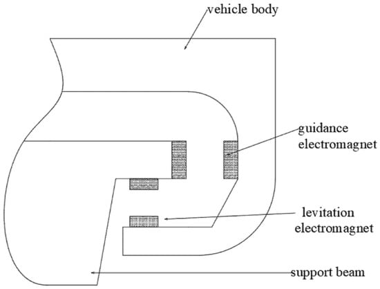
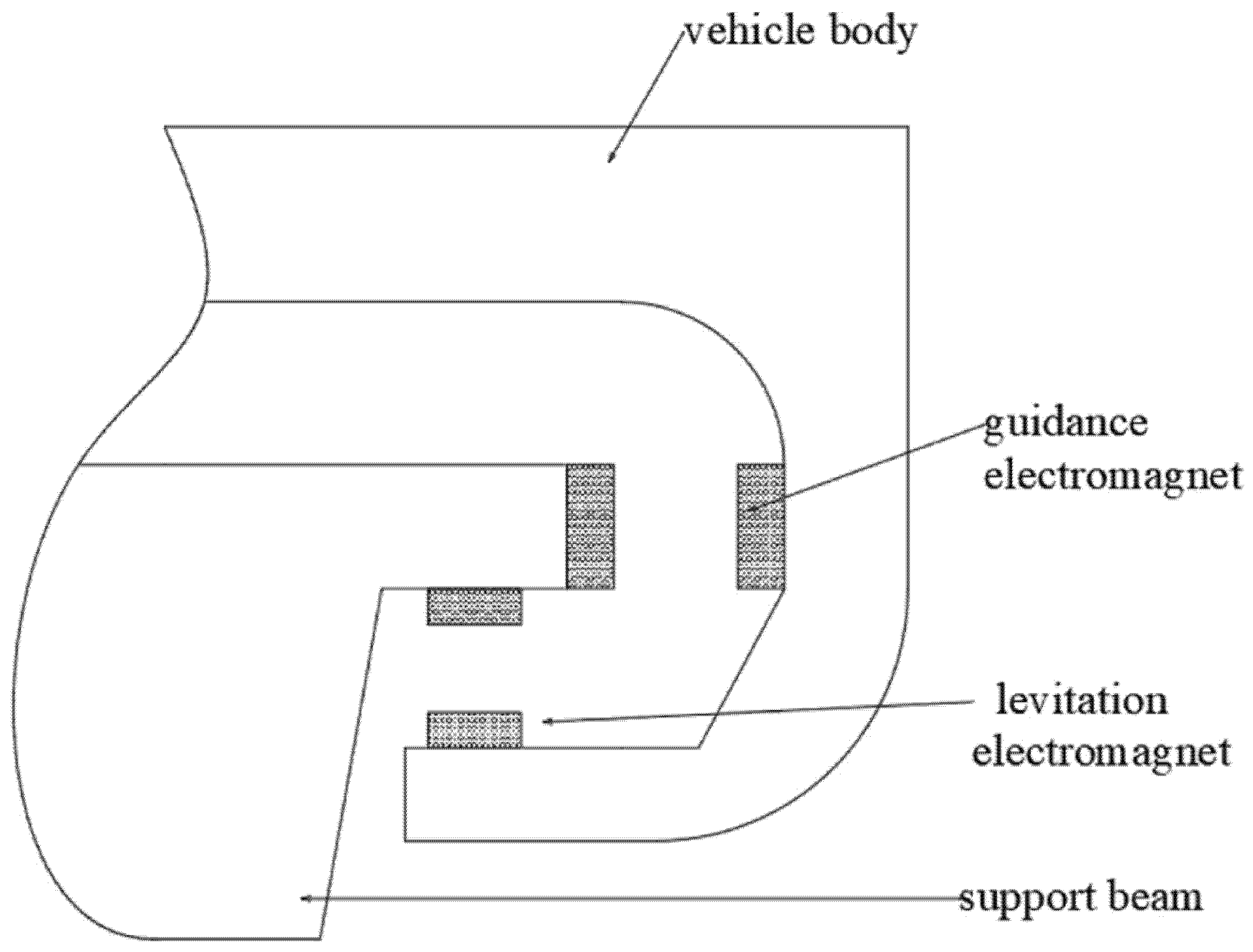
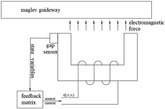
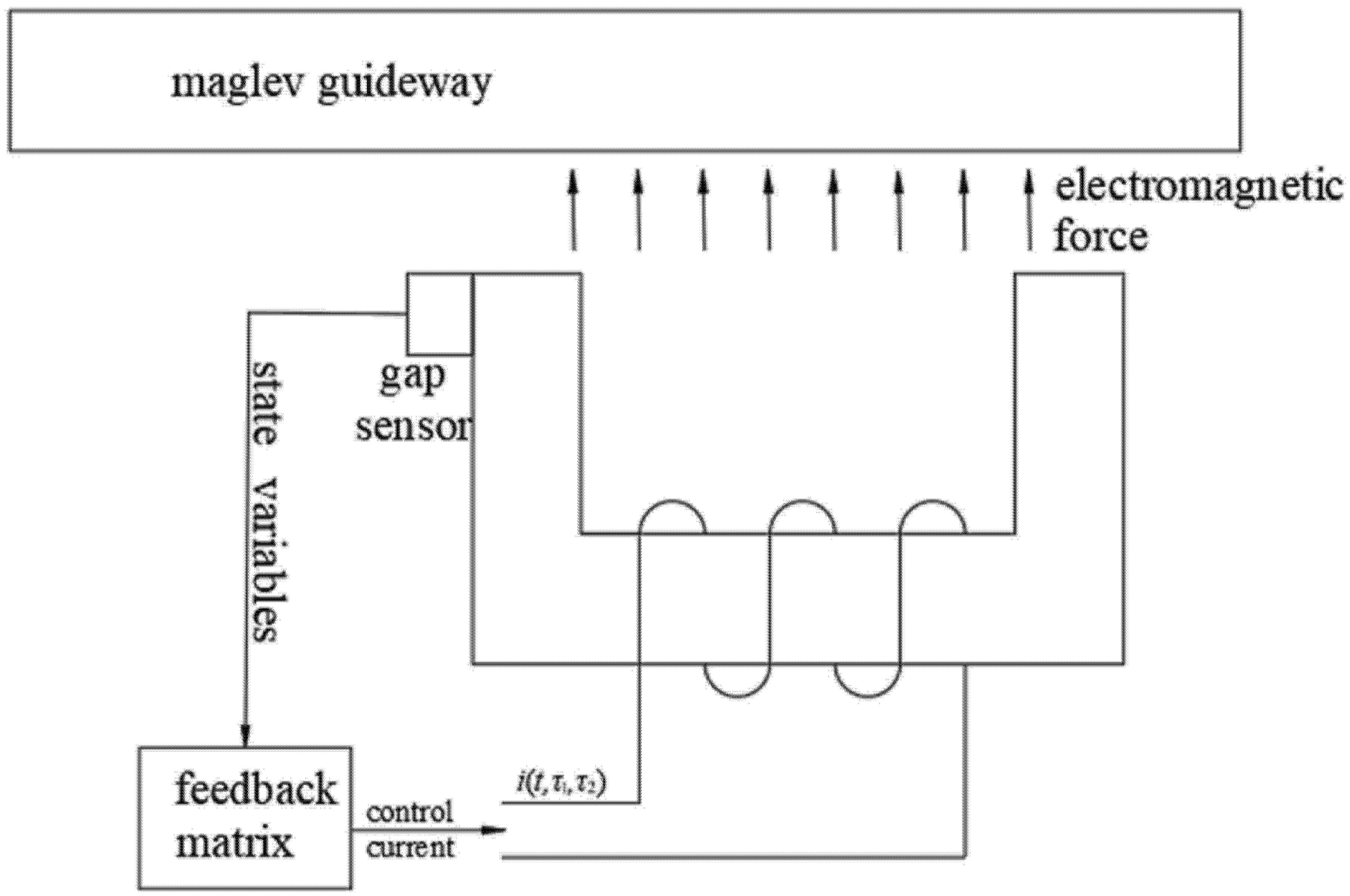
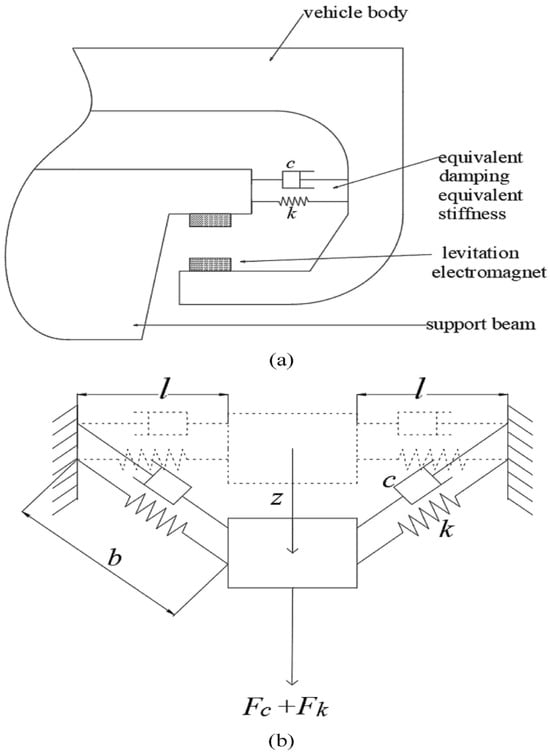
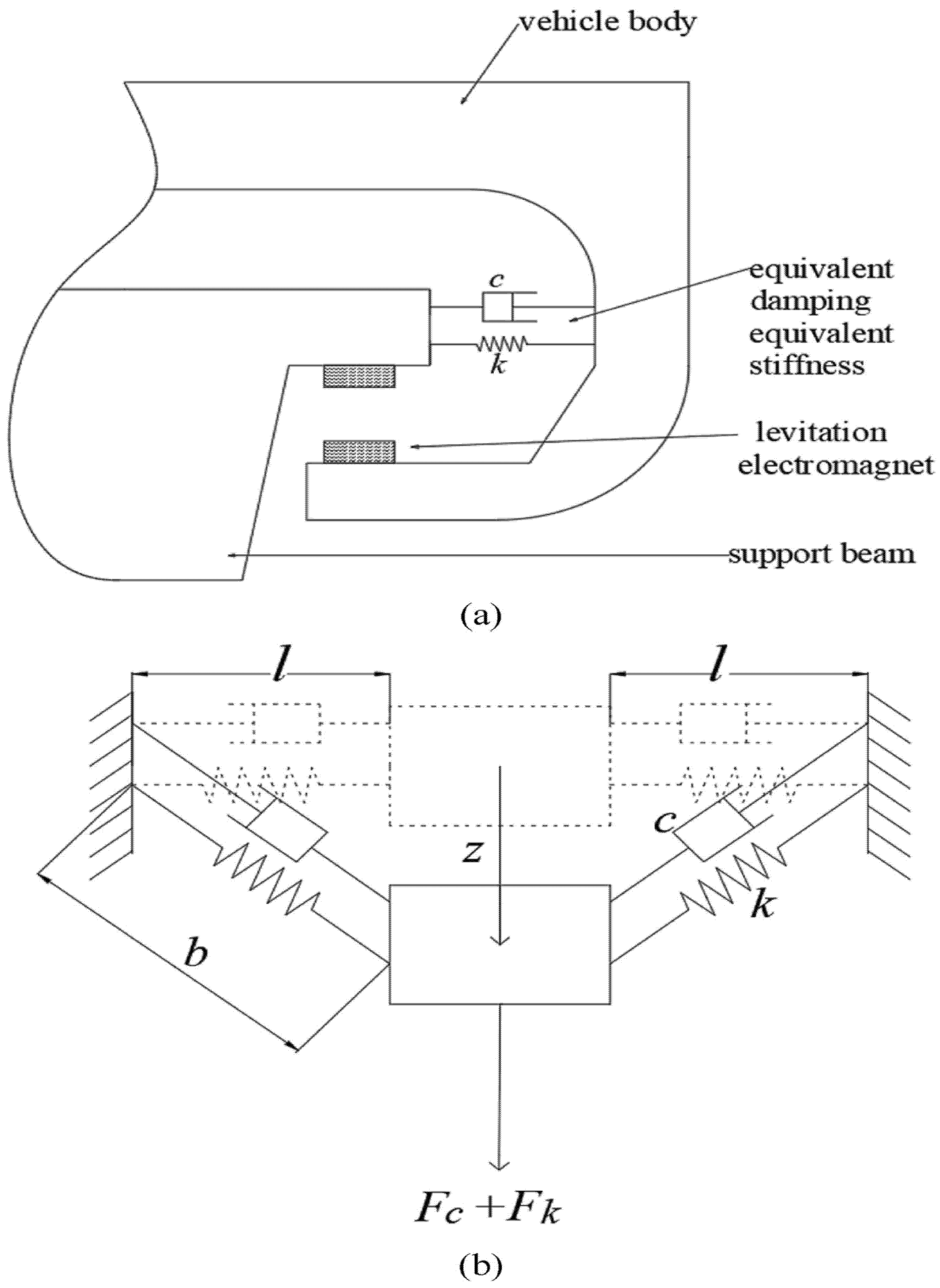
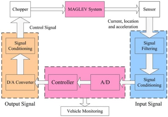
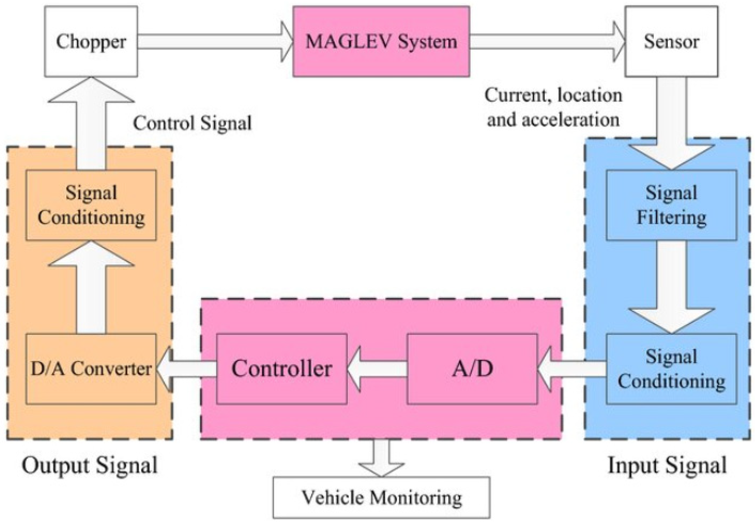
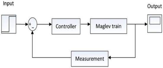
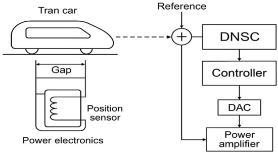
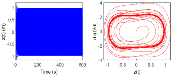
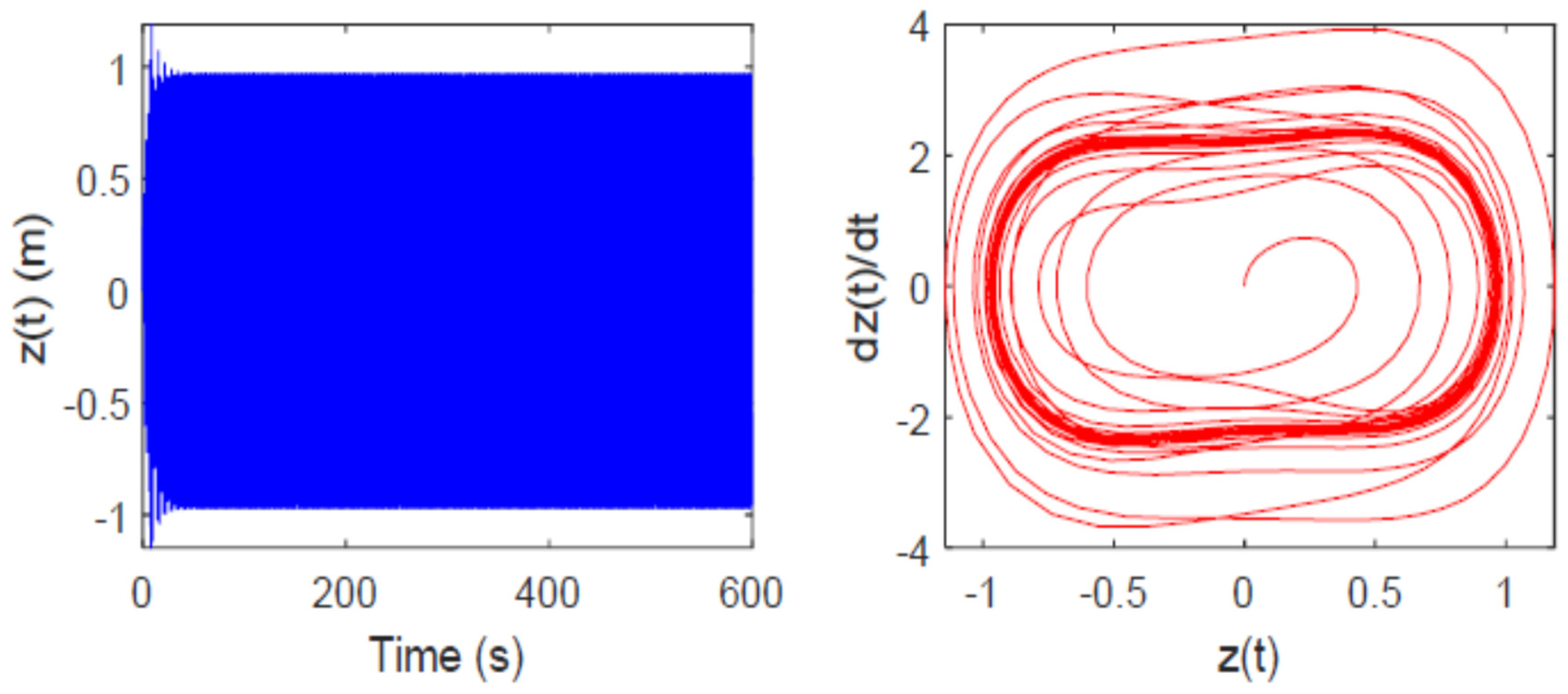
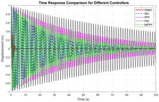
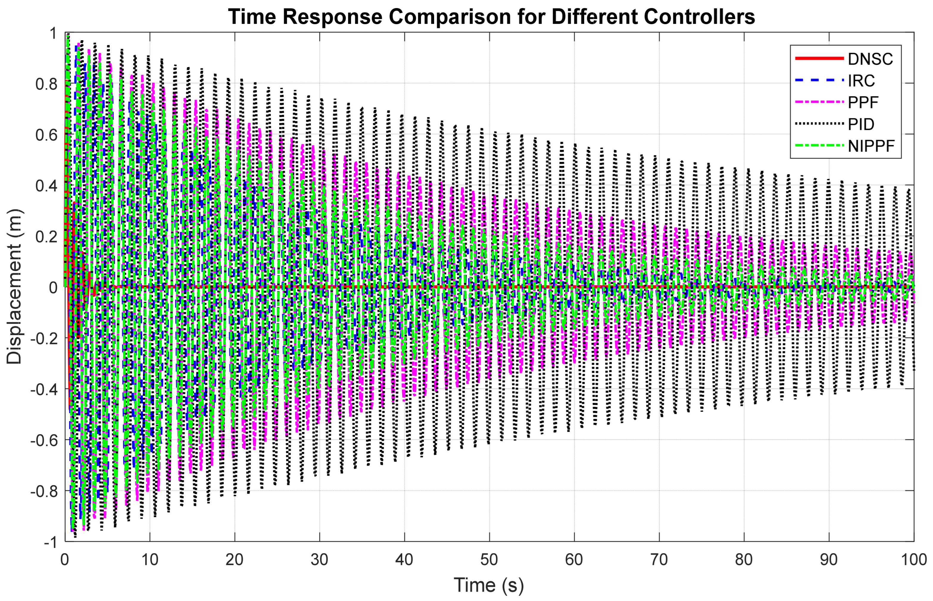
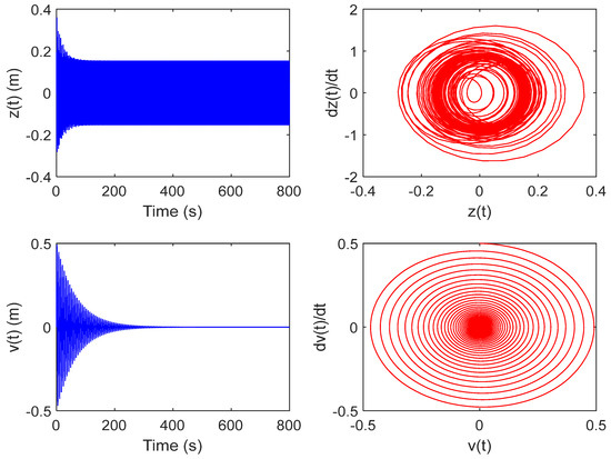
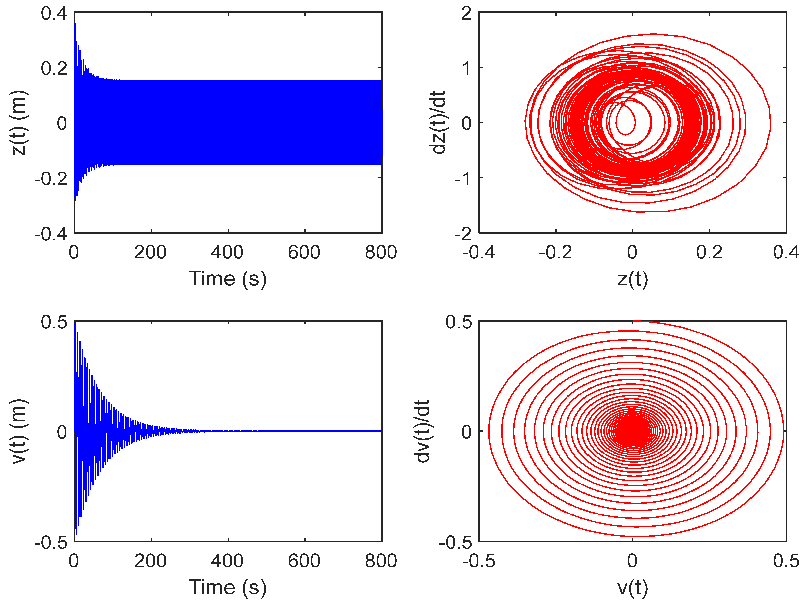
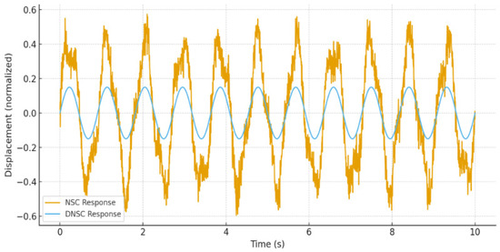
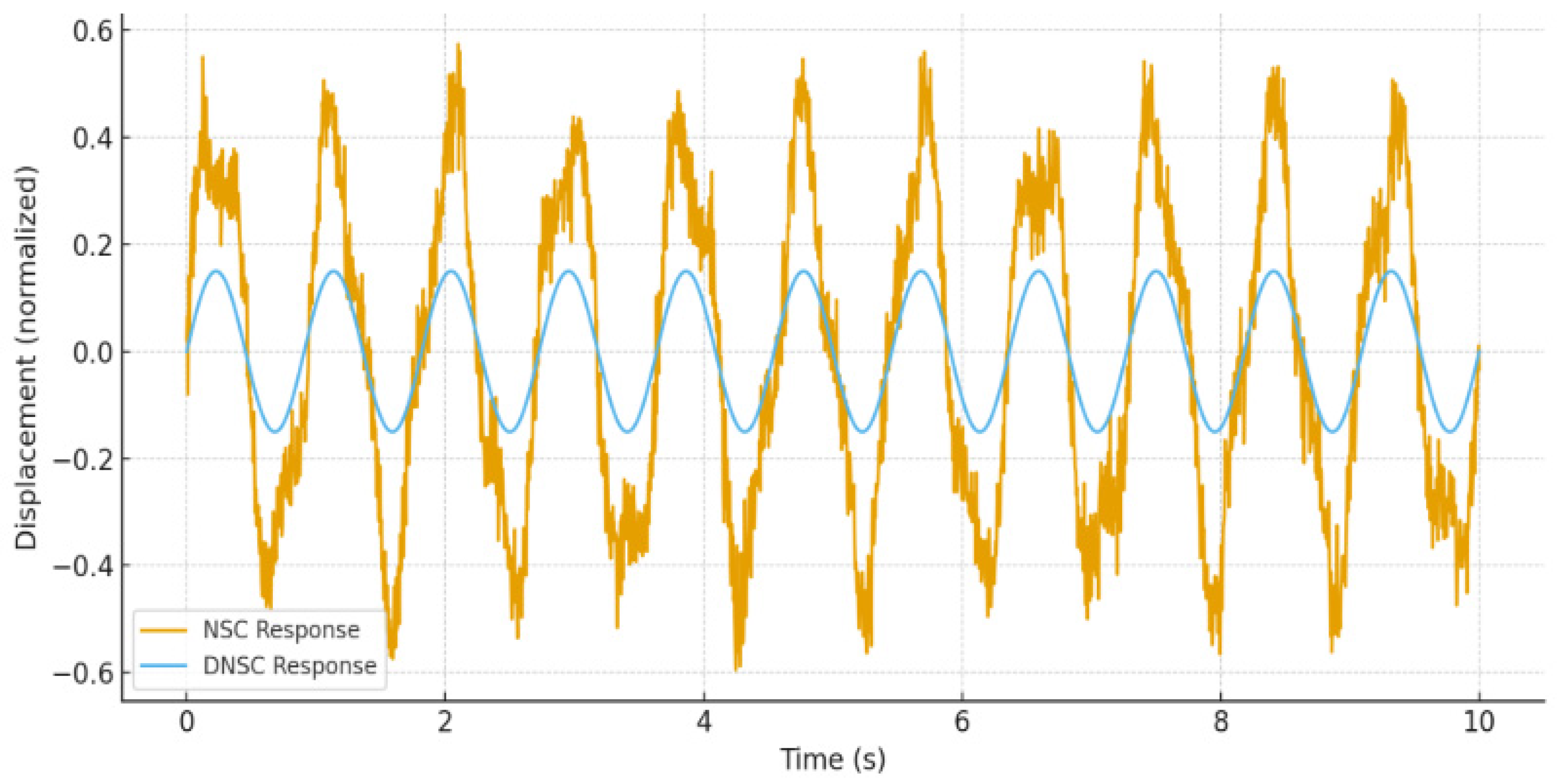
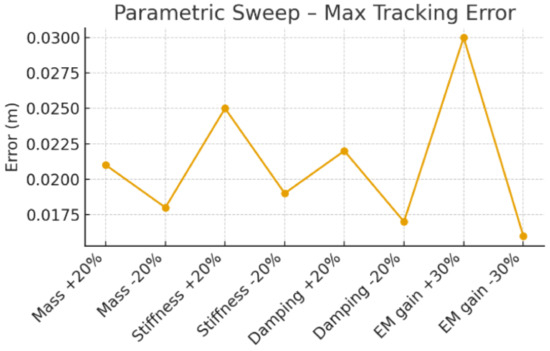
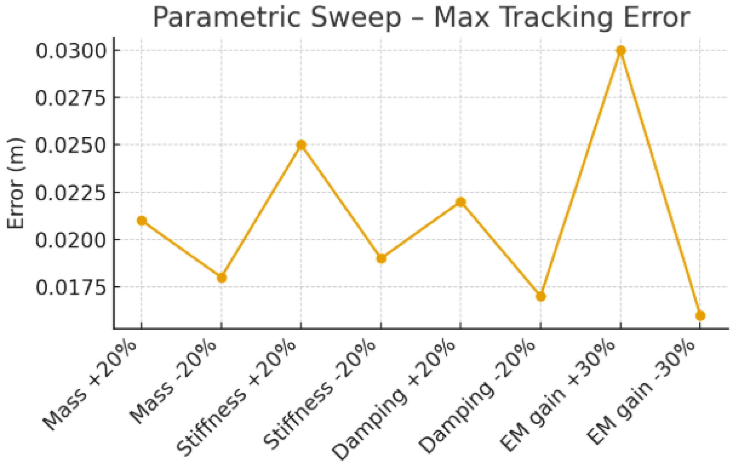
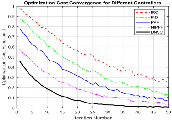
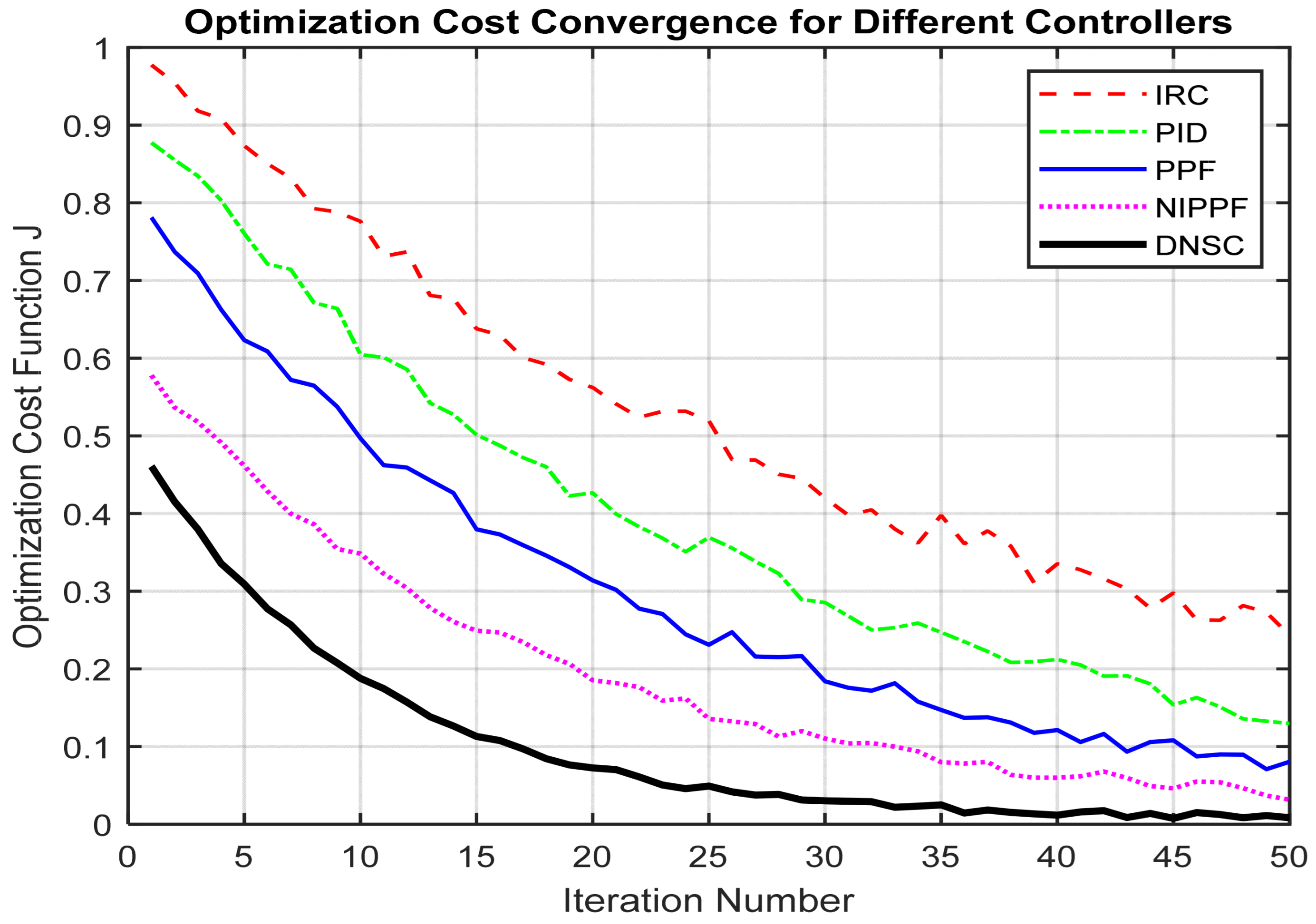
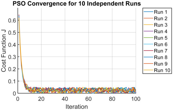
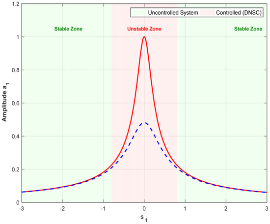
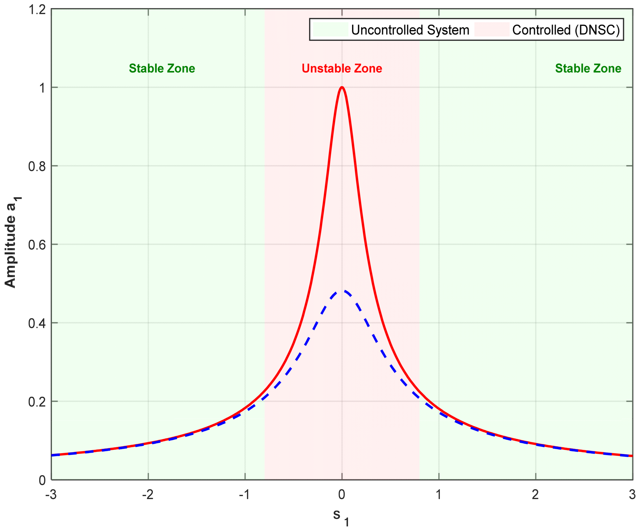
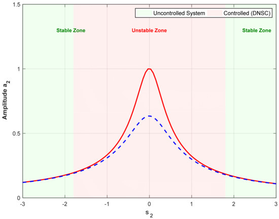
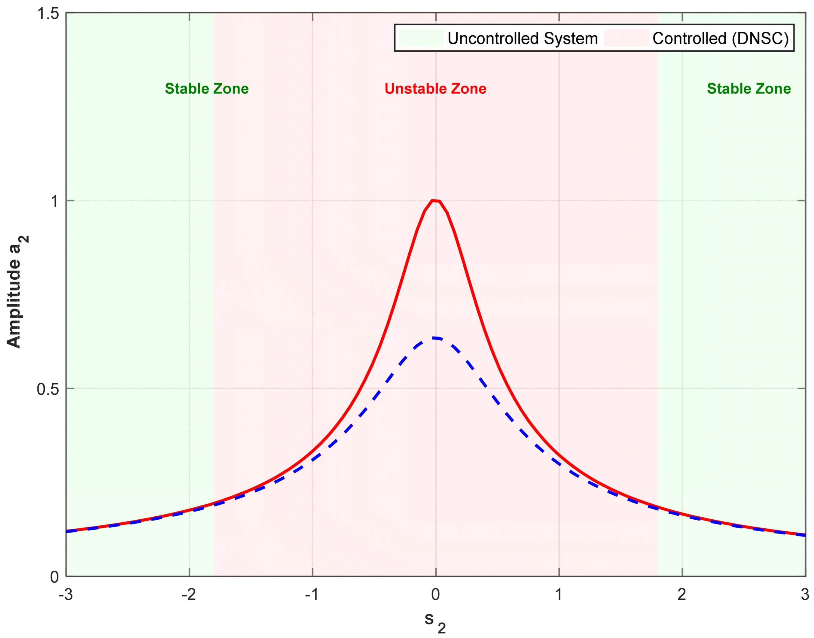
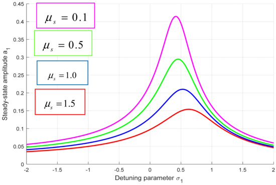
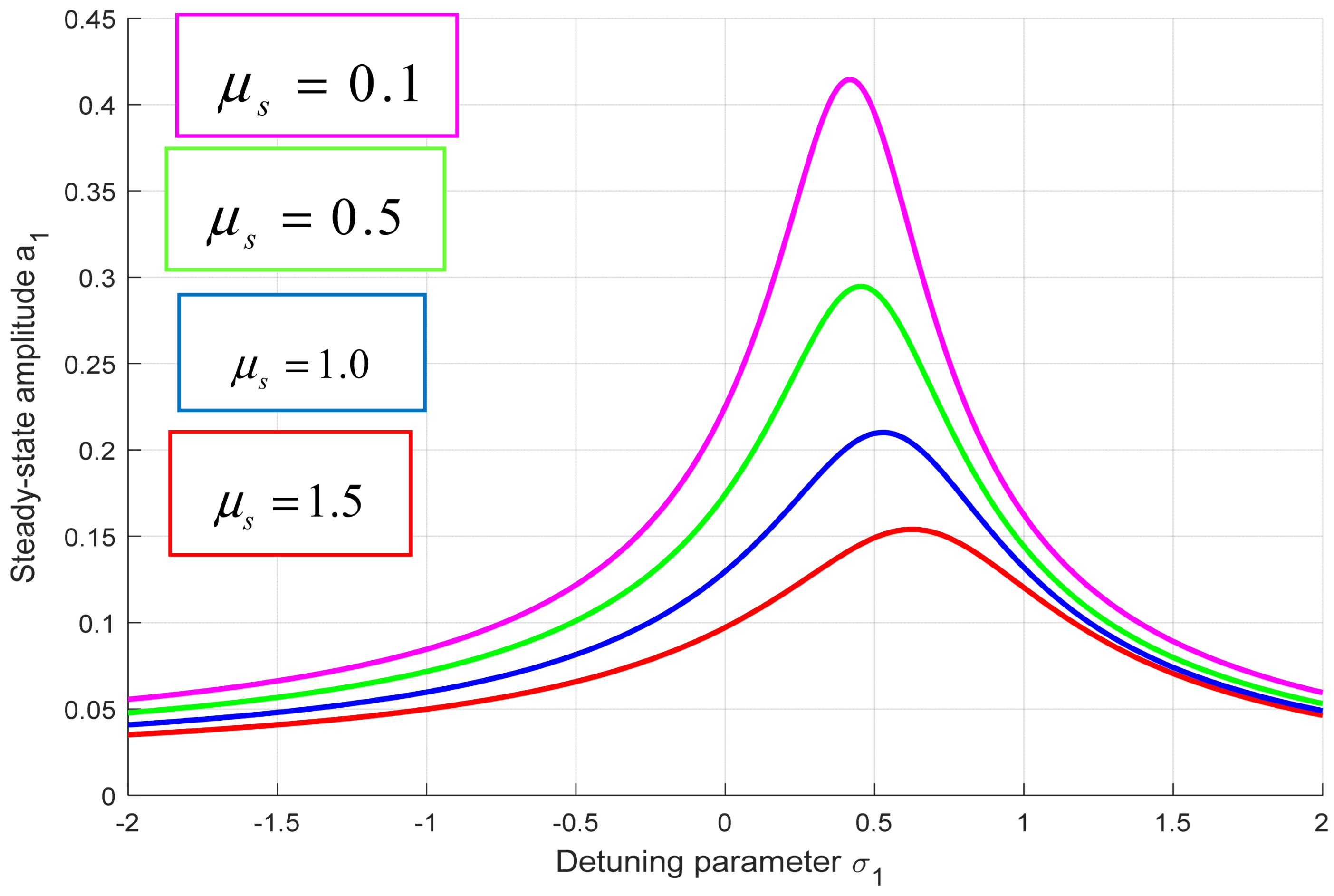
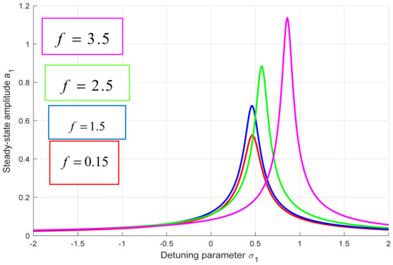
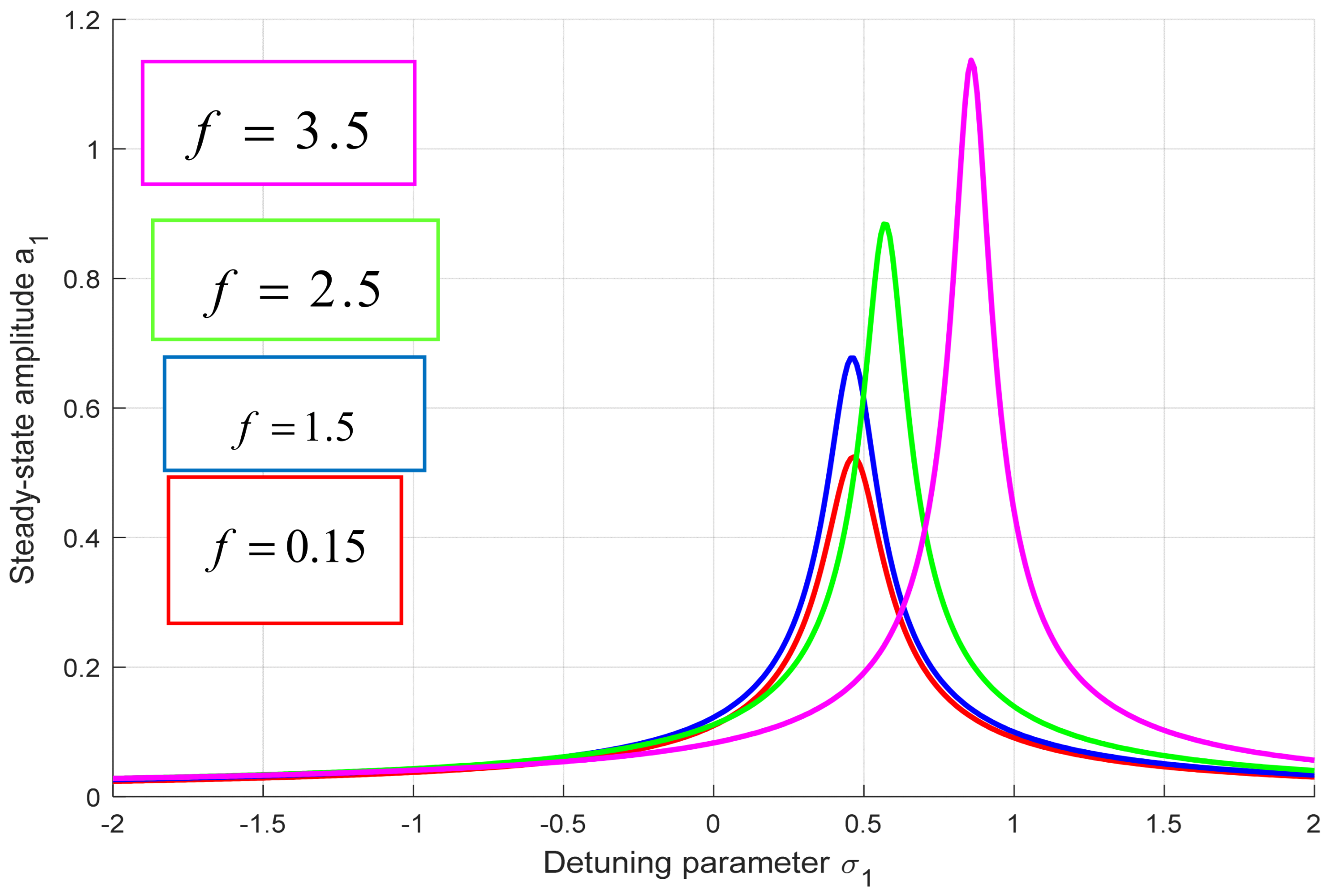
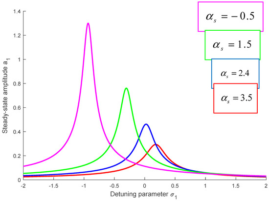
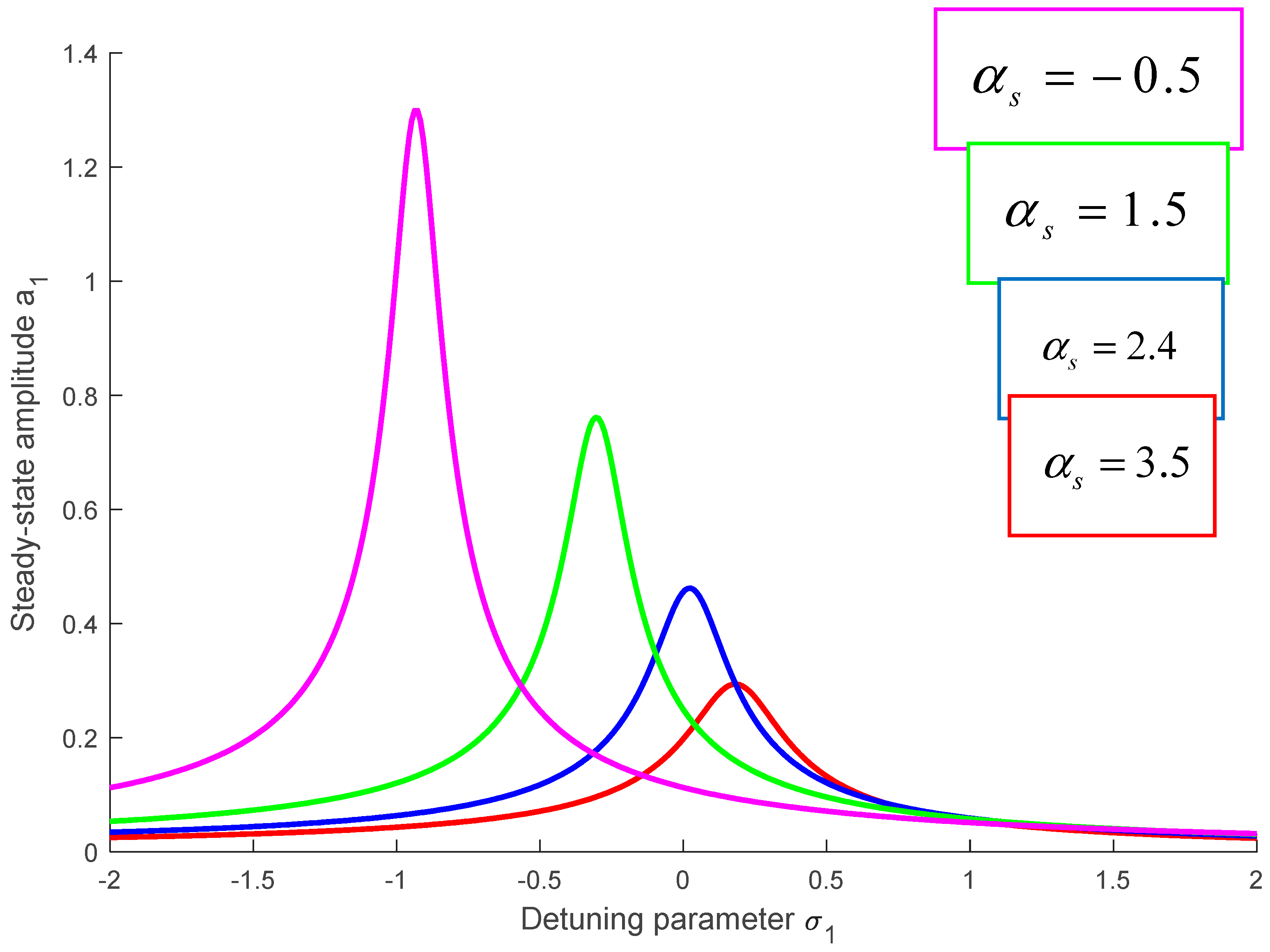
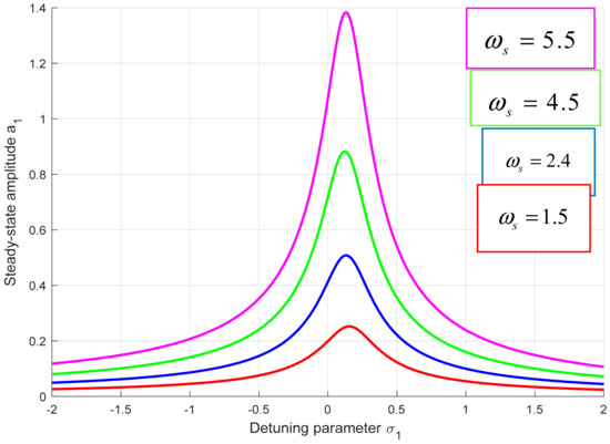
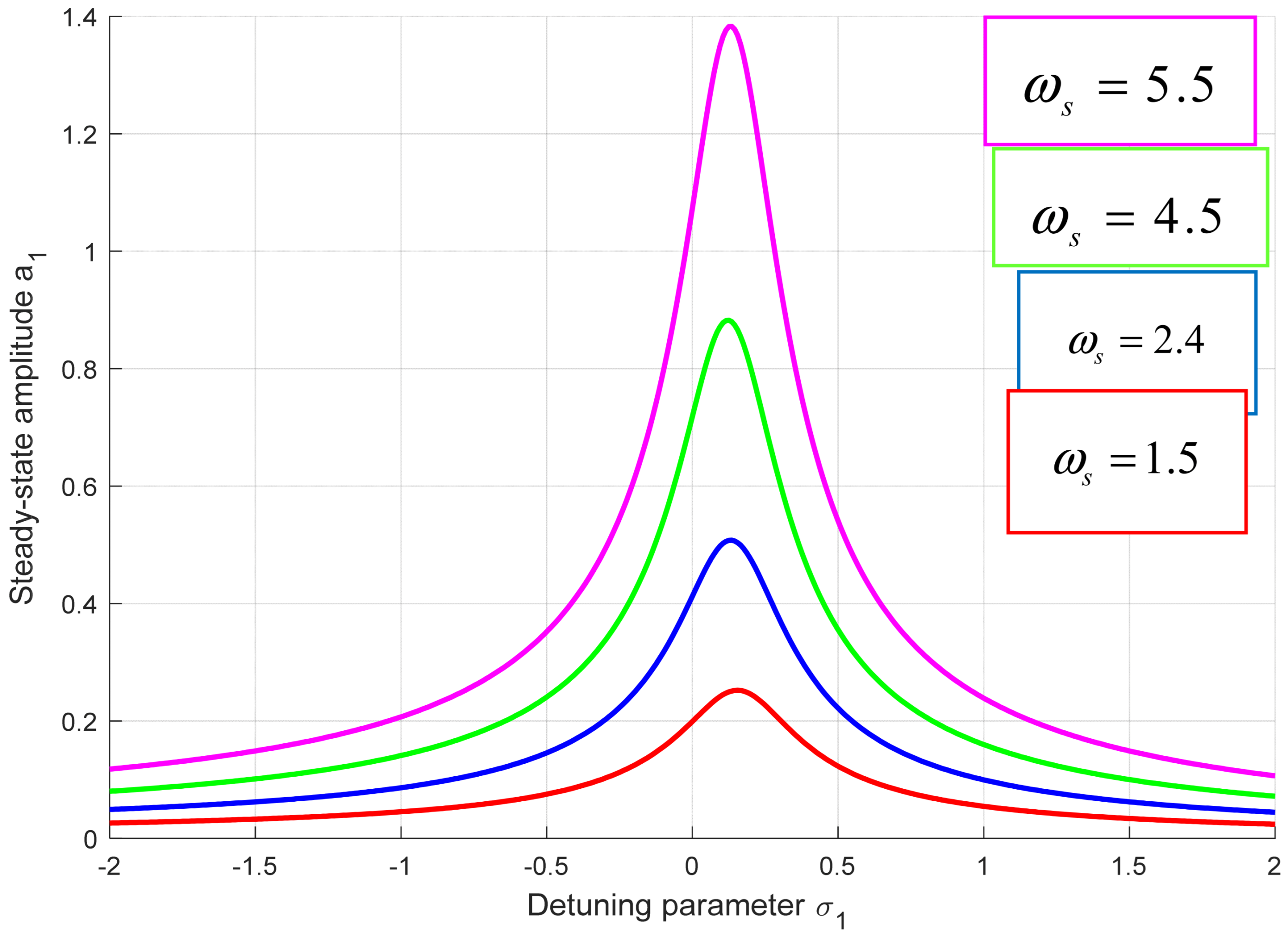
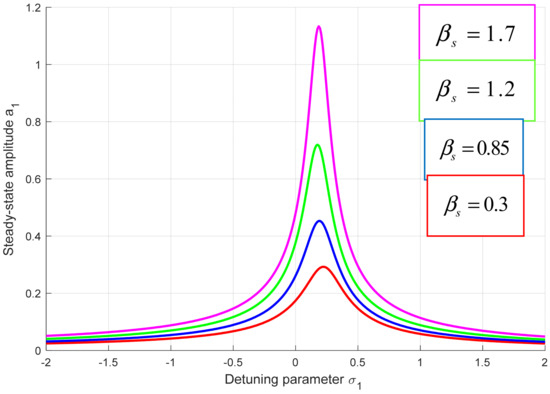
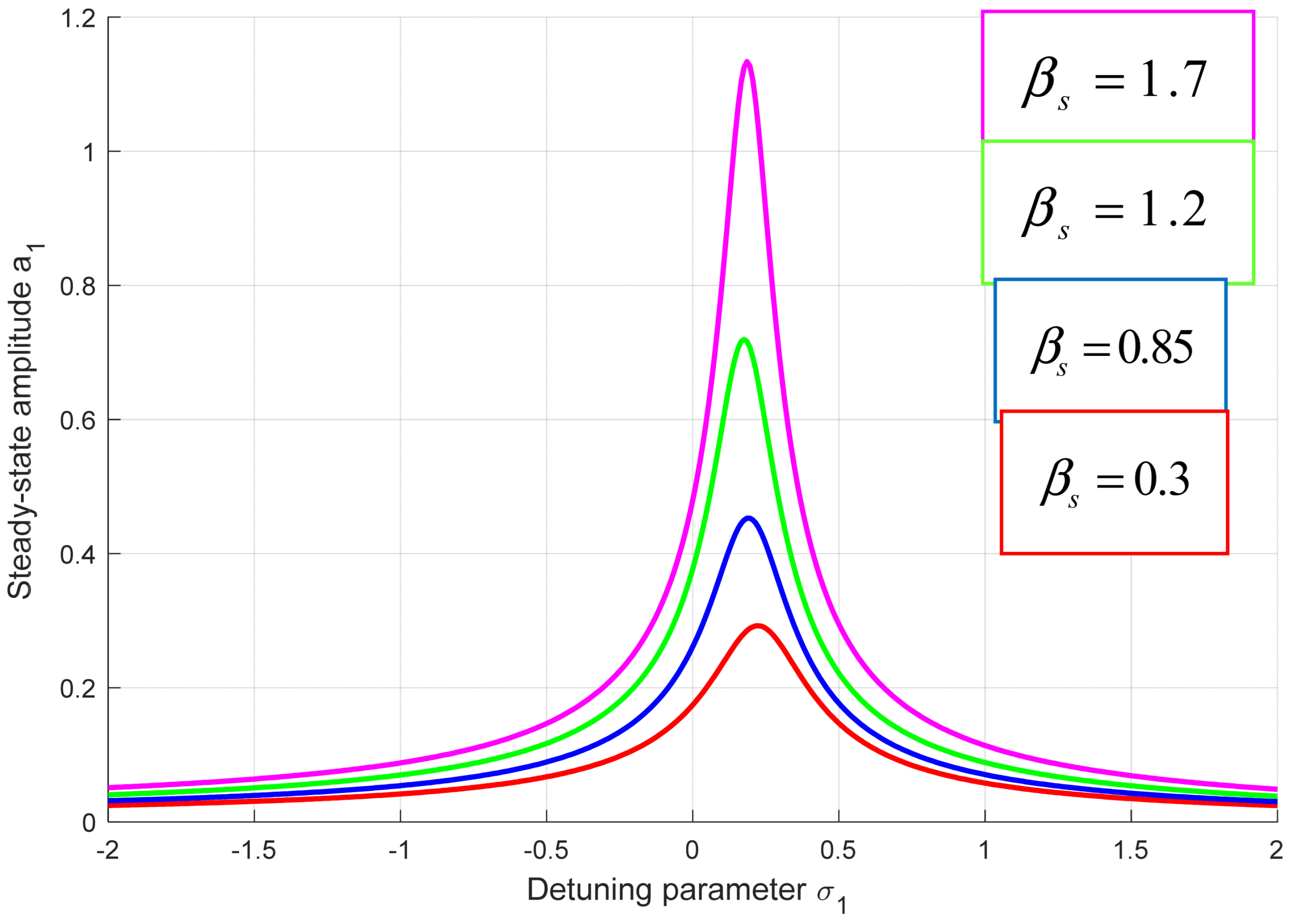
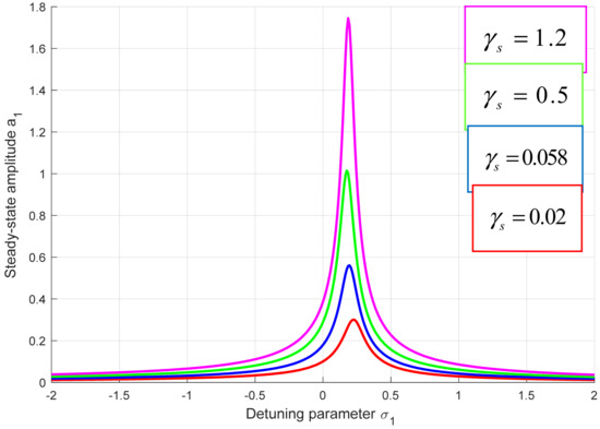
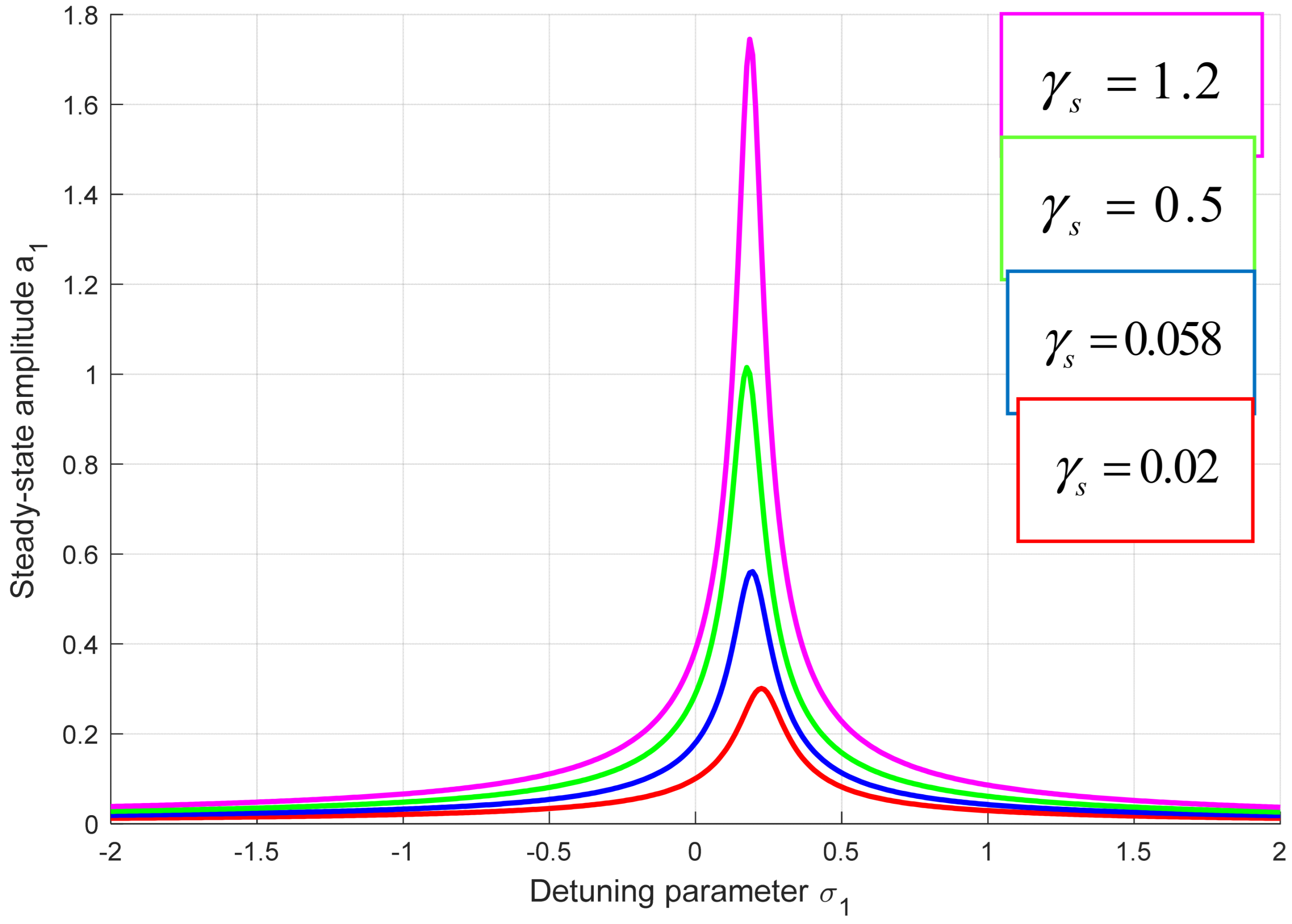
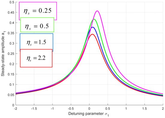
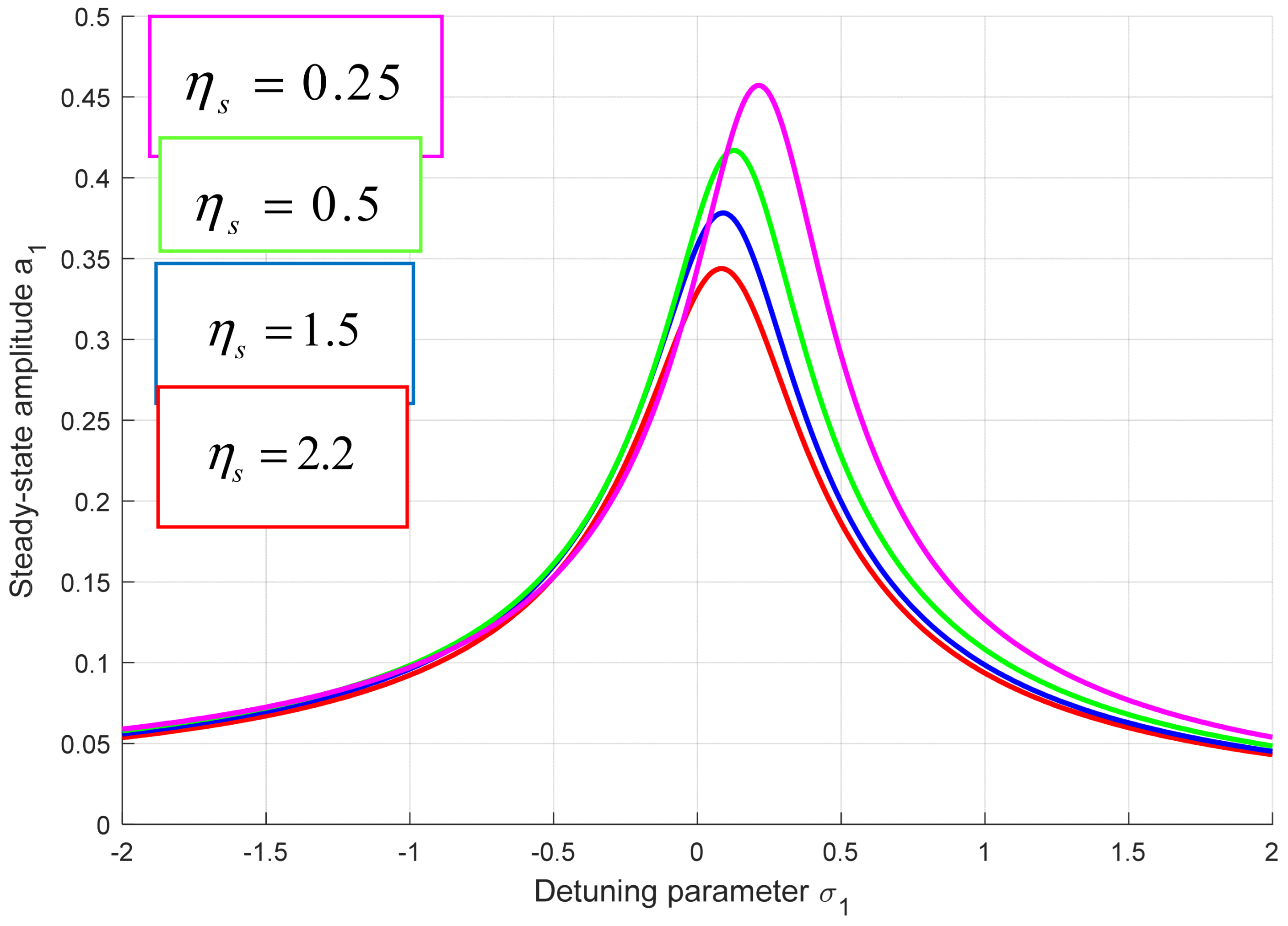
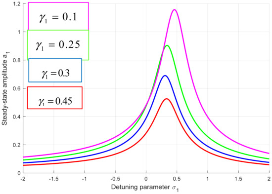
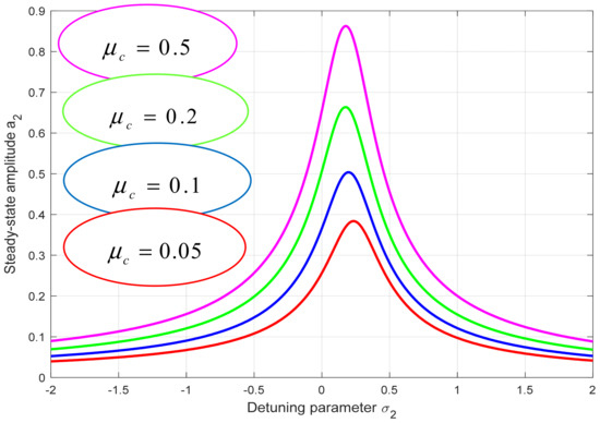
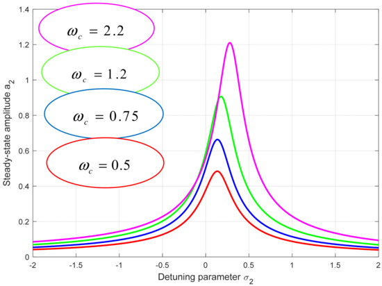
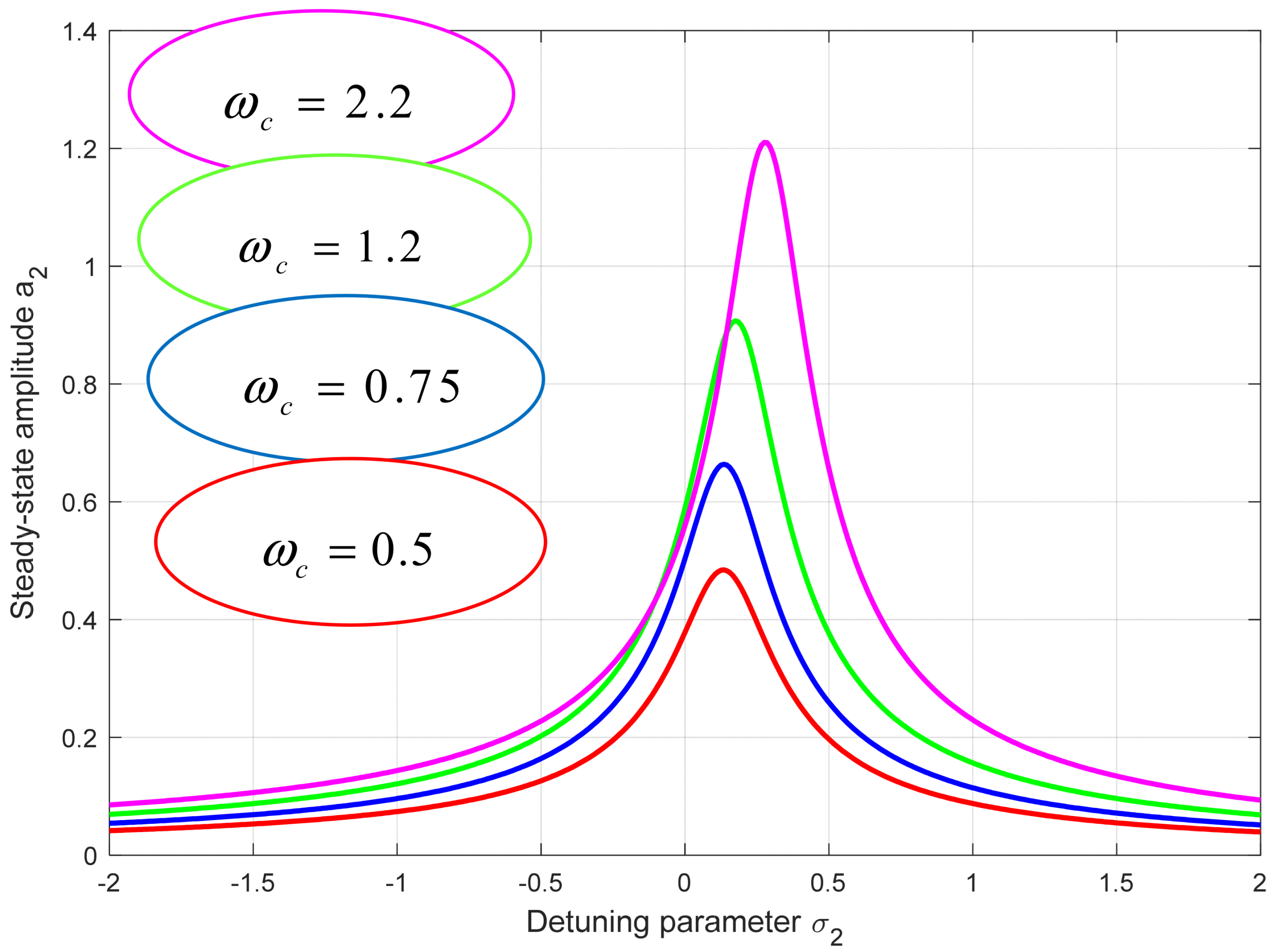
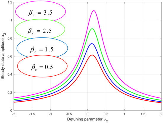
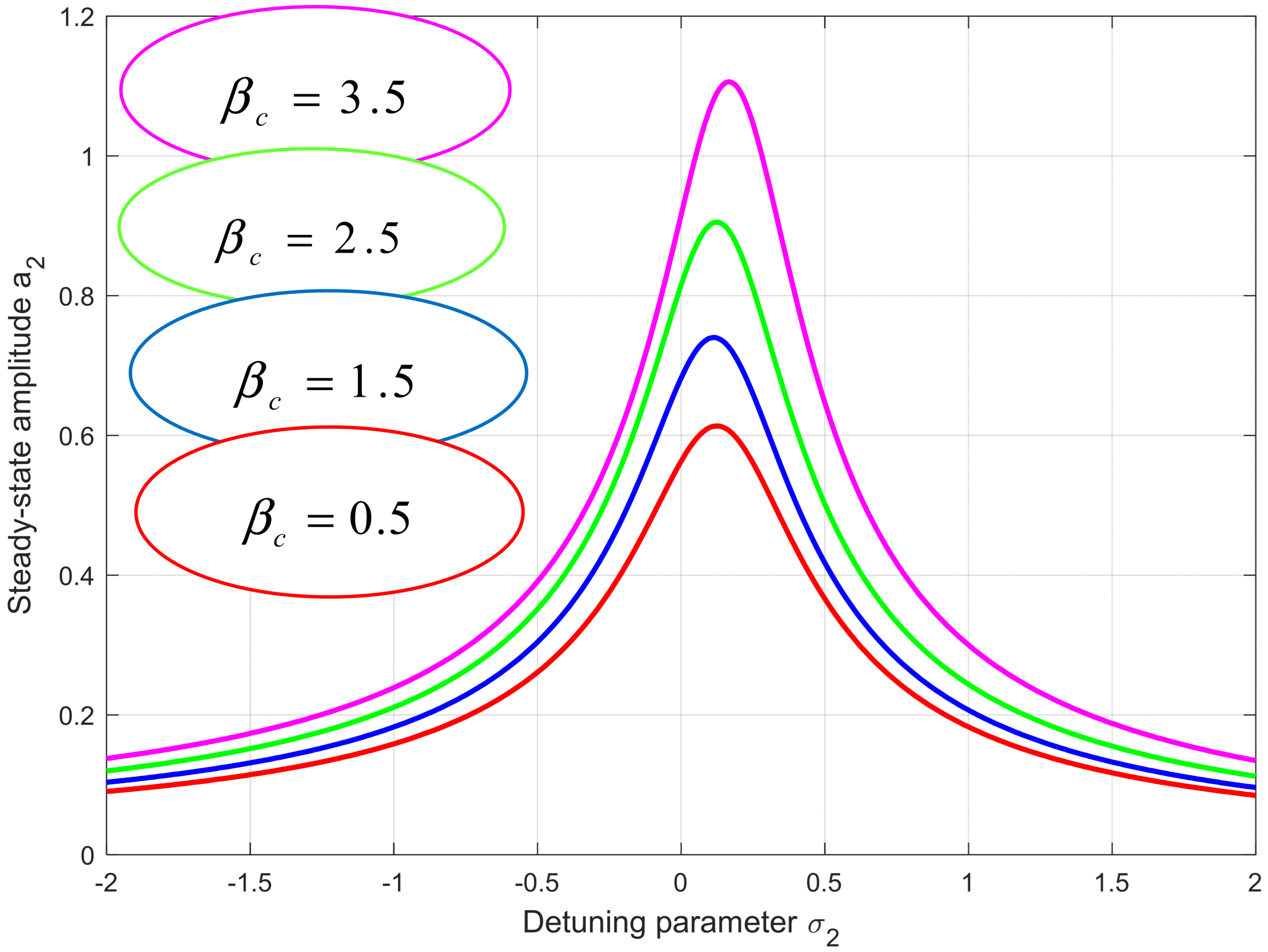
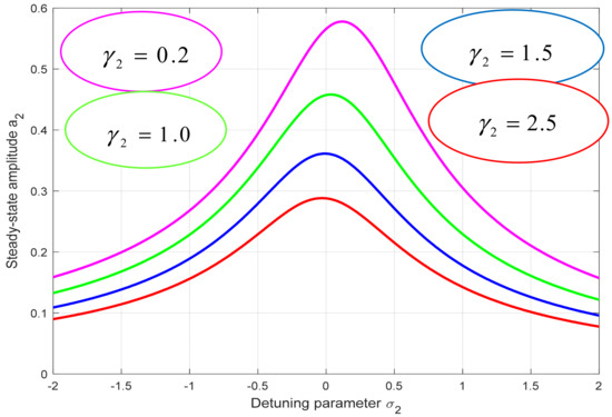
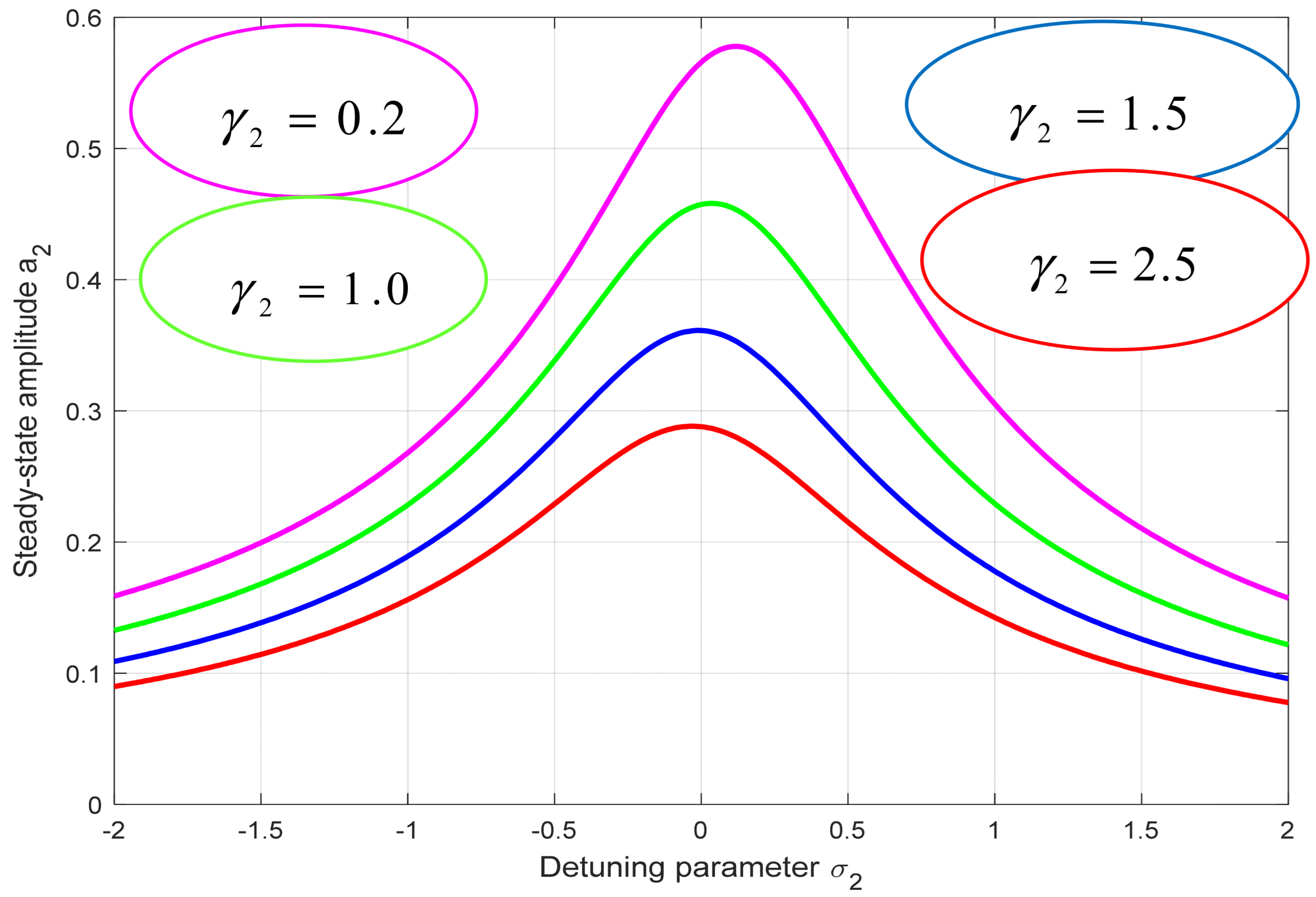
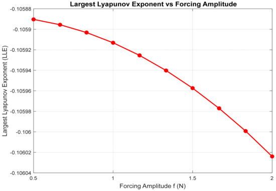
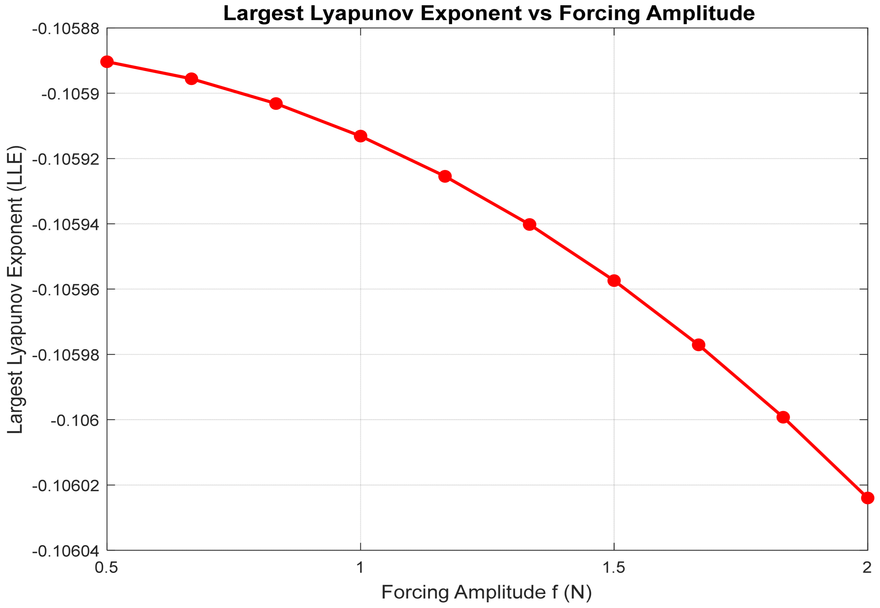
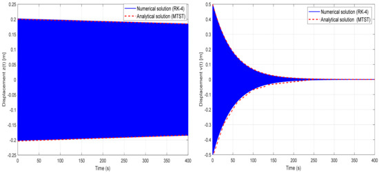
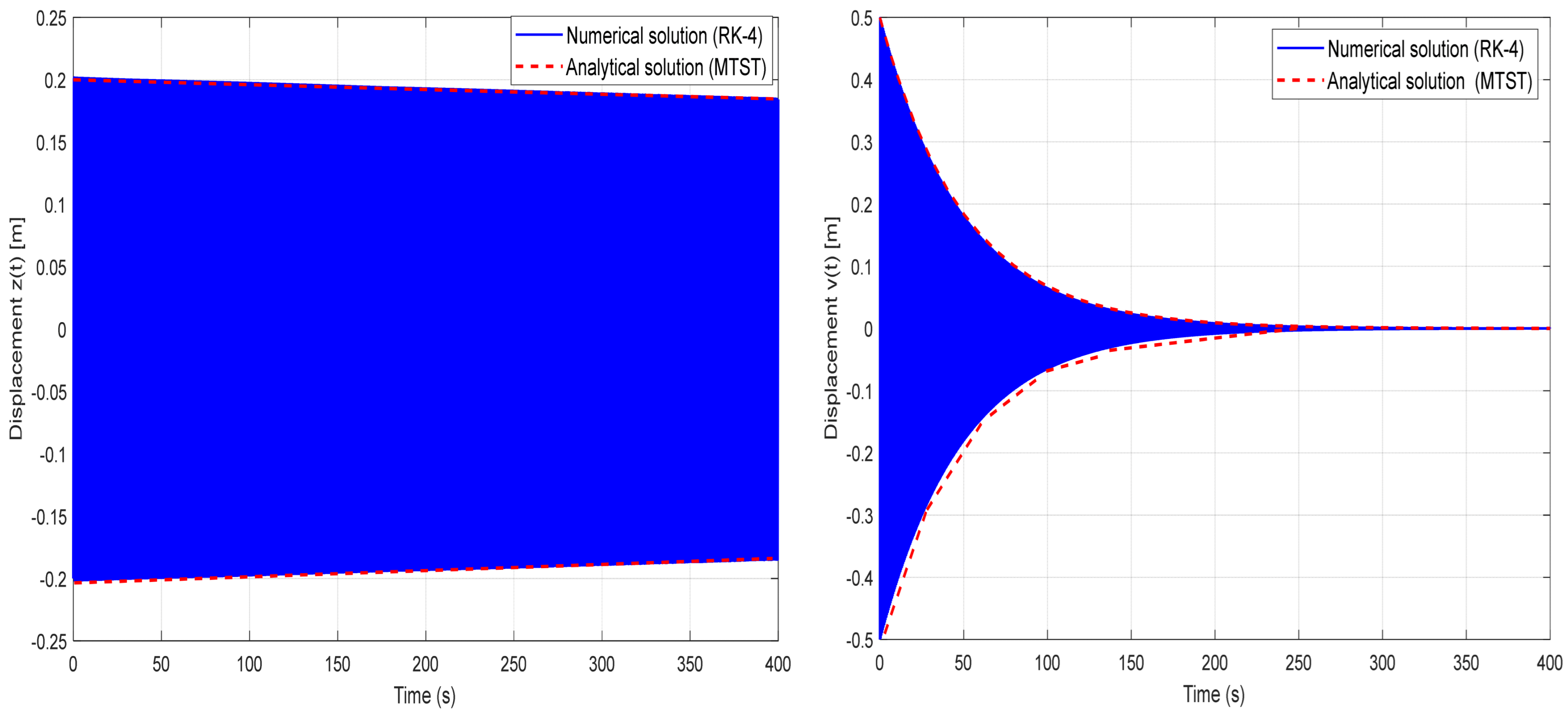
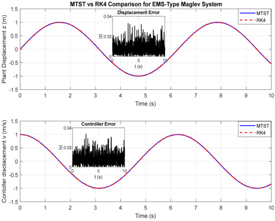
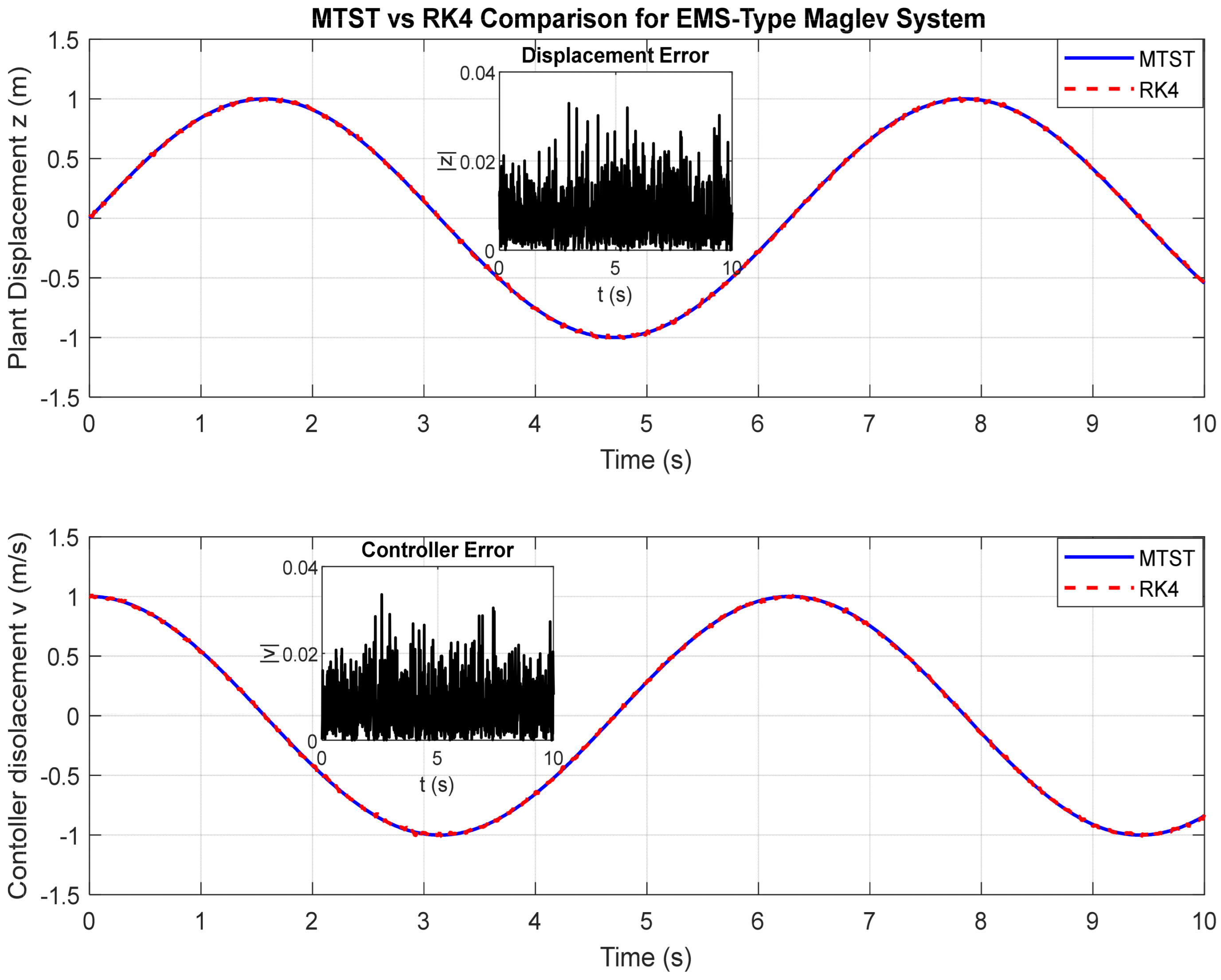
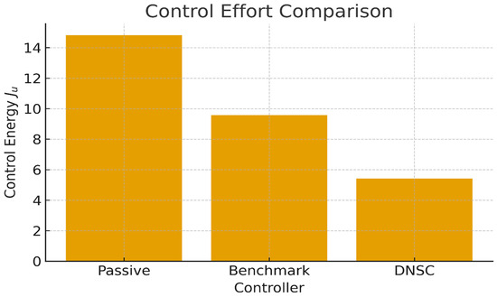
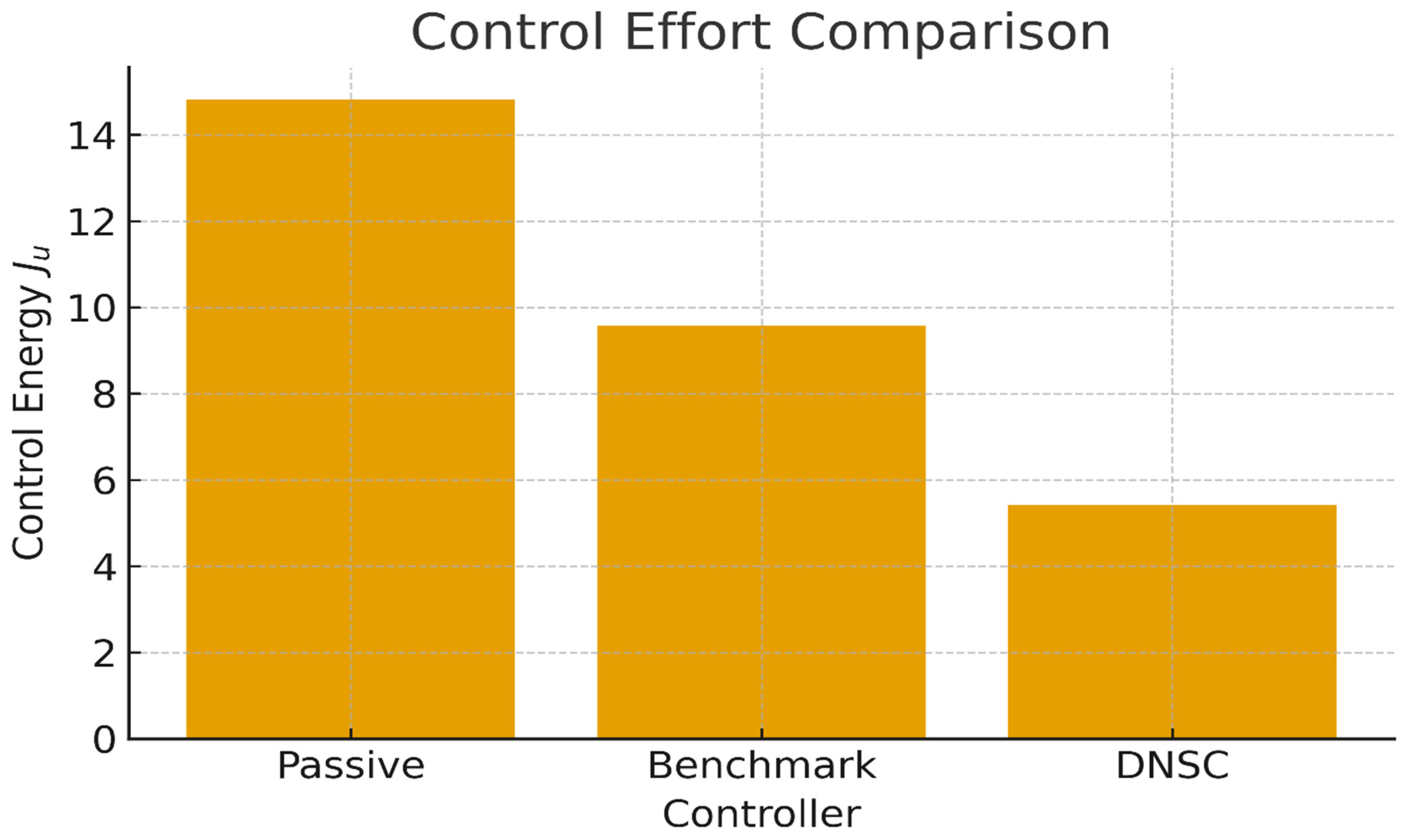
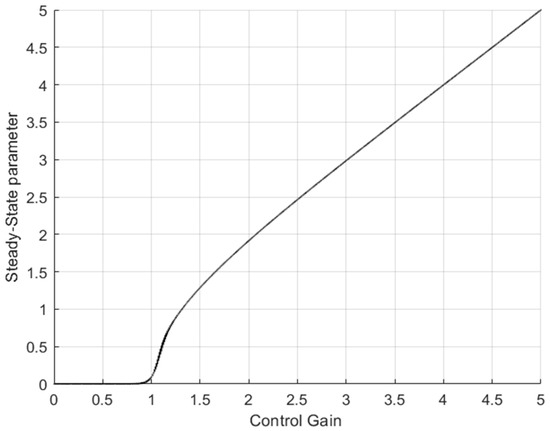
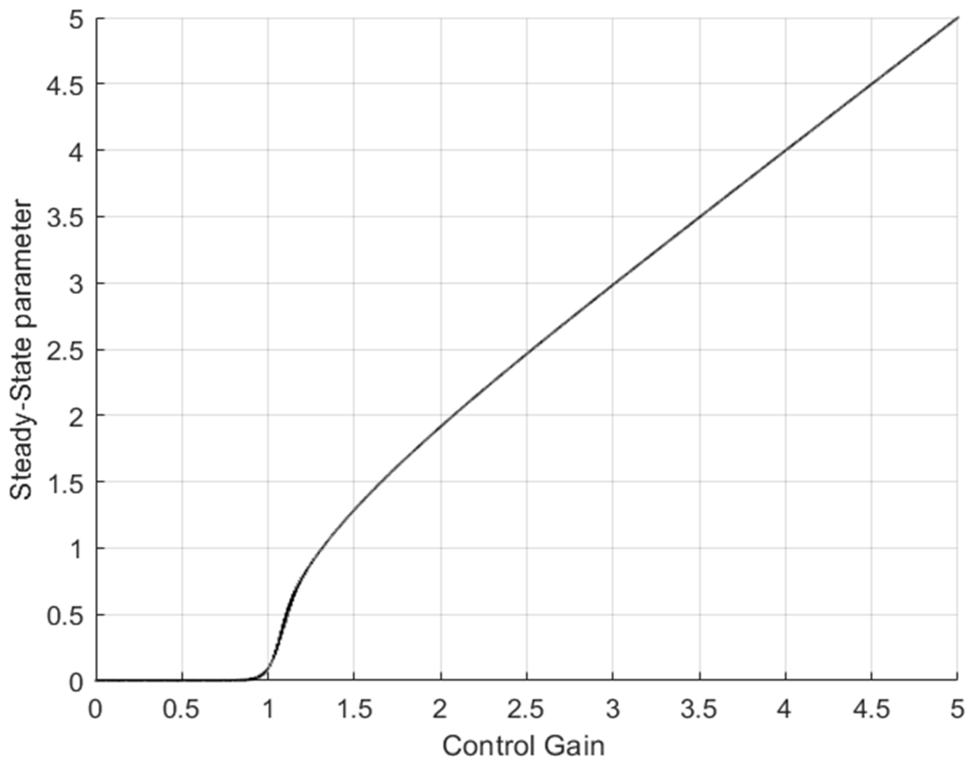
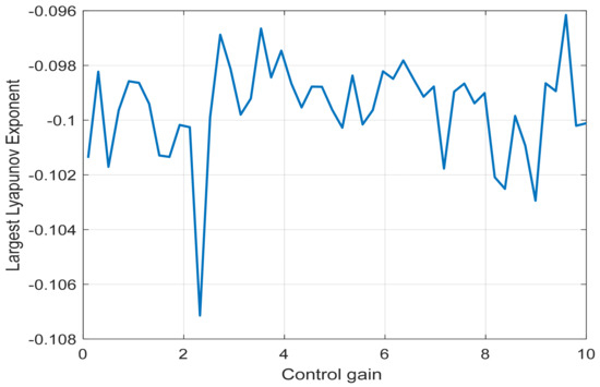
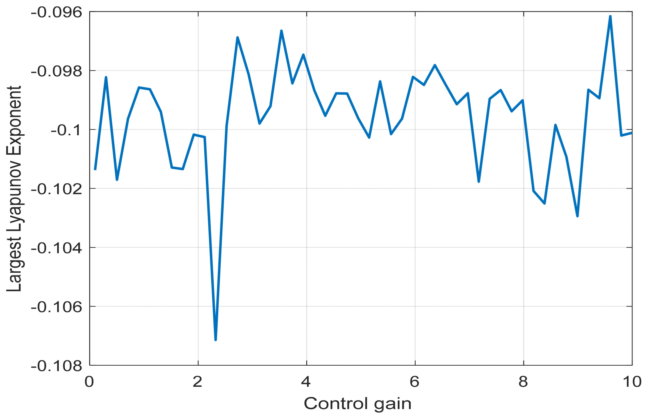
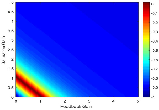
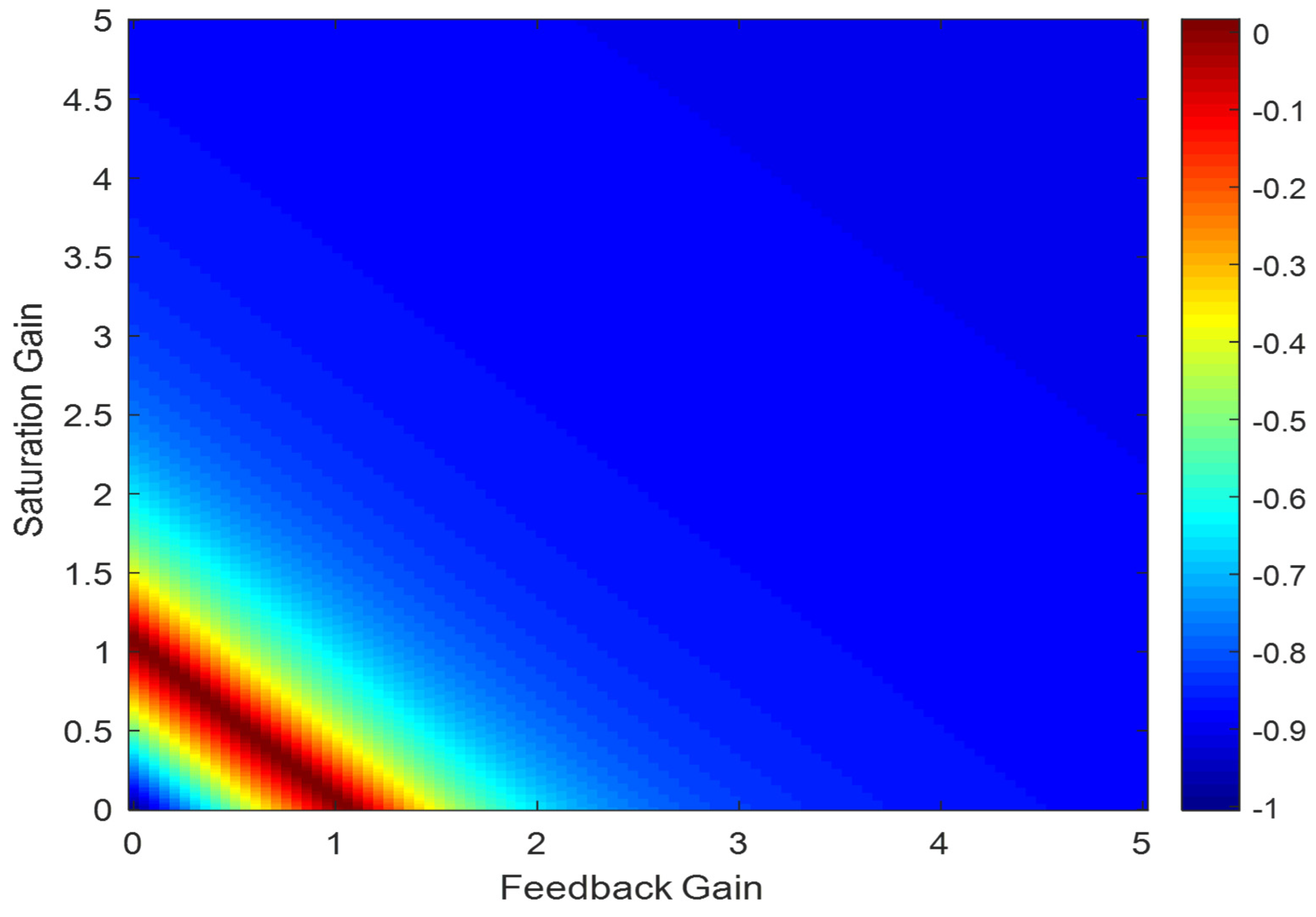

Disclaimer/Publisher’s Note: The statements, opinions and data contained in all publications are solely those of the individual author(s) and contributor(s) and not of MDPI and/or the editor(s). MDPI and/or the editor(s) disclaim responsibility for any injury to people or property resulting from any ideas, methods, instructions or products referred to in the content. |
© 2025 by the author. Licensee MDPI, Basel, Switzerland. This article is an open access article distributed under the terms and conditions of the Creative Commons Attribution (CC BY) license.