Abstract
Synchronization in complex networks mainly considers positive (attractive) couplings to guarantee network stability. However, in many real-world systems or processes, negative (repulsive) interactions exist, and this poses a challenging problem. In this proposal, we present an algorithm to design stable signed Laplacian matrices with mixed attractive and repulsive couplings that ensure stability in both complete and in-phase synchronization. The main result is established through a constructive theorem that guarantees a single zero eigenvalue, while all other eigenvalues are negative, thereby preserving the diffusivity condition. The algorithm allows control over the spectral properties of the matrix by adjusting two parameters, which can be interpreted as a pole placement strategy from control theory. The approach is validated through numerical examples involving the synchronization of a network of chaotic Lorenz systems and a network of Kuramoto oscillators. In both cases, full synchronization is achieved despite the presence of negative couplings.
MSC:
93-10
1. Introduction
Complex networks are arrangements of objects connected by a coupling strength and given a particular topology [,,]. Many natural or artificial phenomena can be represented or described as complex networks, such as research collaborator networks, the WWW, wireless communications, power energy generation and delivery, ecosystems, etc. Thus, the motivation to study these objects and their dynamics becomes more and more interesting and important. Since the beginning of the study of these structures, many problems have been launched and analyzed; a description of problems can be found in []. One of the most studied problems is the synchronization of dynamical systems connected in a network [,,,] mainly due to the potential applications. Synchronization is a phenomenon that occurs when a group of oscillators or nodes in a network exhibit similar behavior. This behavior can be observed in a wide range of systems, from biological networks [,] such as brain neurons to technological networks such as power grids [,]. The study of synchronization in complex networks has been an area of active research in recent years, with researchers investigating various types of couplings between network nodes []. However, a common consideration in the literature is that the coupling strength between nodes or systems is positive (attractive) or, in some cases, zero; the justification for such a consideration is based on the stability of the network, since positive couplings are sufficient but not necessary for network stability [,,]. The condition of positive or same-sign couplings restricts the possibility of studying different kinds of dynamic behavior between nodes. Negative couplings can represent, for instance, inhibitory behavior in a neuronal network; in [], a probabilistic study on the stability of inhibitory and excitatory neuronal networks was presented, where stability was analyzed using the eigenvalues of the coupling matrix. In biological systems, there is evidence of negative autoregulation [] and negative regulation [,]. All these references pose the problem of considering negative couplings in the study of complex networks as a generalization of the types of behavior these networks can exhibit.
However, it is well known that in the real world, interactions between systems are both attractive and repulsive. It is also known that negative (repulsive) interactions produce dynamical phenomena such as instability or anti-phase behaviors. Interesting results have been published in this context [,,]. This refers to the presence of both attractive (positive) and repulsive (negative) interactions between nodes in a network. These interactions can arise due to a variety of factors, such as the physical distance between nodes, the strength of their connections, and the dynamics of their interactions. For instance, in [], the authors present a memristive coupling between two hyperbolic-type Hopfield neurons, which by itself can be a positive or negative coupling, and also show that the synchronization depends on a certain time delay in the coupling.
The use of repulsive and attractive couplings has been applied to study social balance in the dynamics of friendship [], where attractive coupling corresponds to friendly relationships, whereas non-friendly relationships are modeled as negative or repulsive couplings. On the other hand, in the field of neuronal synchronization, [] describes inhibitory and excitatory interactions in neurons, and establishes conditions on such interactions. The most important is that, in order to satisfy or achieve a particular behavior—especially stability—the couplings in the inhibitory subnetwork must be negative, whereas in the excitatory subnetwork the couplings must be positive. Moreover, there is evidence that synchronization between two neural models depends on the excitatory neuron rather than the inhibitory one [].
Research has shown that attractive and repulsive coupling can lead to a rich array of synchronization patterns in complex networks. For example, in some cases, the presence of repulsive interactions can prevent complete synchronization from occurring, resulting in a partially synchronized state []. In other cases, attractive and repulsive interactions can lead to the emergence of complex spatial patterns, with groups of nodes synchronizing in specific regions of the network.
The study of synchronization in complex networks with both attractive and repulsive couplings has important implications for understanding the behavior of real-world systems. For example, in the field of neuroscience, it can help shed light on how brain regions communicate and synchronize during different cognitive processes [,,]. In the field of engineering, it can inform the design and control of power grids and other complex systems [,] to name just a few.
Some results have been reported regarding the analysis of Laplacian matrices and their eigenvalues with mixed negative and positive elements. For instance, in [], the authors reported signed weights for trees. There is reported evidence that negative couplings can lead to instability or anti-phase synchronization in networks [,]. In multiplexed networks, anti-phase synchronization has been observed when all couplings are repulsive in one layer and attractive in the other, and the inter-layer links are negative [,]. Therefore, it could be said that negative or repulsive couplings lead to anti-phase synchronization, in-phase clustering, or instabilities in the network. In the cited references, all connections between nodes are either repulsive or attractive, which leads to stability issues, as this configuration may induce both positive and negative eigenvalues in the coupling matrix [].
The dynamical stability of synchronization in the network is the most important concern. Thus, negative couplings must be arranged in a specific structure within the connectivity matrix—that is, such couplings must have a particular weight and specific location within the network. If the Laplacian matrix possesses sets of positive, zero, and negative eigenvalues, stability cannot be achieved. The authors in [] analyzed several Laplacian matrices and determined such eigenvalue sets, concluding that for stability, there must exist exactly one zero eigenvalue and all remaining eigenvalues must have the same sign.
It is clear that stability is the main concern in the study and design of dynamical systems and networks; therefore, an algorithm for designing mixed couplings is relevant. In terms of synchronization of dynamical complex networks with attractive and repulsive weighted couplings, it is of great interest to achieve complete and in-phase synchronization. In this contribution, an algorithm to determine a family of connectivity matrices is presented. The main characteristics of the proposal are as follows: (a) The algorithm ensures the condition of one zero eigenvalue and a set of eigenvalues with the same sign (diffusivity condition). (b) The elements of the resulting matrix are located in specific positions to preserve the location of the eigenvalues. (c) The algorithm provides a family of symmetric real matrices with adjustable parameters. (d) These parameters can be used to shift the eigenvalues within the desired region of the complex plane. Compared with the aforementioned results [,,,,], our method allows, a priori, the definition of the eigenvalue distribution, and therefore the stability of the dynamical network can be ensured through proper adjustment of the weights between nodes.
A method is proposed to construct matrices of size , with mixed positive and negative elements, that satisfy the eigenvalue conditions for stability []. The proposed method allows the construction of matrices representing all connected networks with different weights between nodes. It is important to emphasize that the negative couplings are symmetric, which means that . In this context, it is widely reported that for diffusively coupled nodes [,,], the coupling matrix satisfies the zero row-sum condition and therefore, meets the stability requirements reported in [].
The paper is organized as follows: Section 2 describes the stability of complex networks and presents the main contribution regarding the generation of families of connectivity matrices. In Section 3, an example of synchronization is provided to illustrate the feasibility of the procedure. Finally, Section 4 offers concluding remarks.
2. Model Network with Mixed Couplings
Consider a dynamical network of N identical nodes, diffusively and linearly coupled, whose dynamics are governed by the following state equations
where are the state variables of the system node i, is a continuous vector field, represents the coupling strength and is the outer coupling matrix that specifies which state variables are coupled. The coupling elements are the entries of the matrix C which corresponds to the Laplacian matrix of the network (possibly signed), due to its symmetric structure and zero row-sum property and are defined such that if there is a connection between nodes i and j then ; otherwise , the diagonal elements are defined as . Note that the matrix C defined above corresponds to the (signed) Laplacian matrix of the network, since it satisfies the zero row-sum condition and symmetric structure characteristic of Laplacian formulations.
The eigenvalues of the Laplacian matrix of a network determine the stability of synchronization. These conditions form the basis from which the synchronization of complex networks emerges [,,]. Consider Equation (1) with the coupling strength set to for simplicity. In this case, the coupling strength is assigned to each pair of connected nodes and may differ across the network. In other words, the strength between any two nodes can vary and may be either positive or negative. Accordingly, the stability depends on the placement of the eigenvalues, which is influenced by the weights between the nodes.
It is well known that the coupling strength acts as an amplifying factor of the influence of node i on node j. This influence can be either positive or negative, leading to distinct behaviors in the dynamics of the affected nodes. The main objective is to achieve synchronization between systems coupled through both negative and positive weights. To this end, an algorithm is proposed for constructing coupling matrices that include some negative weights. These coupling matrices satisfy the connectivity condition, namely, they have one eigenvalue with multiplicity one.
It is also known that connectivity matrices are symmetric and satisfy the zero row and column sum conditions, which guarantee the existence of a spanning tree—i.e., there are no isolated nodes. The algorithm for generating coupling matrices with mixed weights is stated as follows:
Theorem 1.
Let be a symmetric connectivity matrix with . If the elements of C are given as follows:
Step 1: Off-diagonal elements ()
The off-diagonal elements follow a periodic pattern based on :
where , , and , are adjustable parameters.
Step 2: Diagonal elements ()
The diagonal elements are computed to ensure that the sum of each row is zero:
Additionally, the diagonal elements can be expressed as:
where:
Then, the matrices C generated by the algorithm satisfy the following properties:
- 1.
- Symmetry: for all and the eigenvalues of the matrices are real.
- 2.
- Zero row sum: for each row i.
- 3.
- Eigenvalue structure: The matrix has exactly one zero eigenvalue () and negative eigenvalues ( for ). This means that there is only a eigenvector.
- 4.
- Semidefiniteness: The matrix is negative semidefinite, i.e., for all .
- 5.
- Zero Determinant: .
Proof.
To demonstrate the properties of C, we analyze its spectral characteristics:
Symmetry
Suppose that the matrix C is given as step 1 and step 2, this is for all with and , then then by construction of the matrices this description corresponds to a symmetric matrix and this ensures the existence of real eigenvalues.
Zero row sum
Let us suppose that the condition holds, this implies that there exists a zero eigenvalue, the vector lies in the null space of C. Therefore, is always an eigenvalue of C.
Negative Eigenvalues
Suppose from Step 2 that the condition holds, there is one and only one , since the null space of the matrix C is of dimension one, thus, there are matrices with and by Gershgorin’s theorem it can be confirmed that all eigenvalues lie in the left half-plane of the complex plane and the remaining eigenvalues are negative due to the structure of C, which resembles a generalized Laplacian matrix with mixed weights.
Semidefiniteness via Sylvester’s Criterion
Suppose that the matrix C is constructed by Steps 1 and 2, by induction let us suppose that for a matrix , the leading principal minors alternate in sign starting with a negative one. Now construct by adding an extra row and column, preserving symmetry and the pattern of the off-diagonal elements as defined in the Steps 1 and 2. Although the diagonal elements change slightly, they follow a predictable pattern and remain negative with absolute values dominating the sum of the off-diagonal entries in their respective rows. Therefore, the leading principal minors of order 1 to in have the same sign as those in , since the overall structure of the submatrices remains sufficiently stable. This implies that the minors of also alternate in sign starting with negative. Hence, by induction, the sign pattern holds for the family of matrices, and by Sylvester criterion the matrices C are negative semidefinite.
Therefore, these properties not only validate the construction of the matrix but also the stability and this complete the proof. □
The algorithm proposed in Theorem 1 defines a family of symmetric matrices that fulfill the essential conditions for stability in complex networks with mixed couplings (attractive and repulsive). These matrices have one single zero eigenvalue associated with a constant eigenvector 1 and the remaining eigenvalues are real and negative, then the resulting matrices are negative semidefinite. This property guarantees that the network is diffusive and capable of achieving complete and in-phase synchronization, even with strategically placed negative couplings. In addition, the adjustable parameters u and v allow for the modification of the spectral placement of the eigenvalues on the left half of the complex plane. This feature, therefore, provides the ability to tune the dynamics of the network for specific application needs.
It is well known that synchronization in networks with diffusive couplings is strongly influenced by the spectral behavior of the matrix that defines the connections between nodes. In this work, the matrix C acts as a Laplacian matrix, and its eigenvalues play a key role in the stability analysis of the system. In particular, it is required that the nonzero eigenvalues be located in the negative region of the real axis (or the complex plane), as this condition guarantees convergence to a synchronized regime. Therefore, examining the position of the eigenvalues is not a minor issue, but a fundamental part of the design of connectivity matrices that allow stable synchronization.
The algorithm can be stated in the steps as follows. Given integers , the following steps define a family of coupling matrices:
- Choose parameters , as connection weights.
- Construct the symmetric matrix C using Equations (1)–(4), where each entry is defined based on a modular positioning.
- Verify that the resulting matrix satisfies one zero eigenvalue and the remaining eigenvalues negative.
Remark 1.
The method uses the module to generate the mixed couplings of the connectivity matrix. This function defines the periodicity and symmetry of the matrix entries, which in turn determine the location of the eigenvalues.
With this algorithm, one can generate coupling matrices with mixed positive and negative values. An interesting observation is that the Gershgorin Theorem is used to localize the eigenvalues of the connectivity matrices, in the sense that the spectrum of the matrix C is fully contained into the union of the Gershgorin disks . Let be the closed disk centered at with radius ; therefore, every eigenvalue of C lies within at least one of these disks . However, for the proposed method, some of the radius are greater than the absolute value of the center . As a result some regions of the union of the disks lie in the right-hand said complex plane, as illustrated in Figure 1. For stability analysis, however, this information alone is not sufficient.
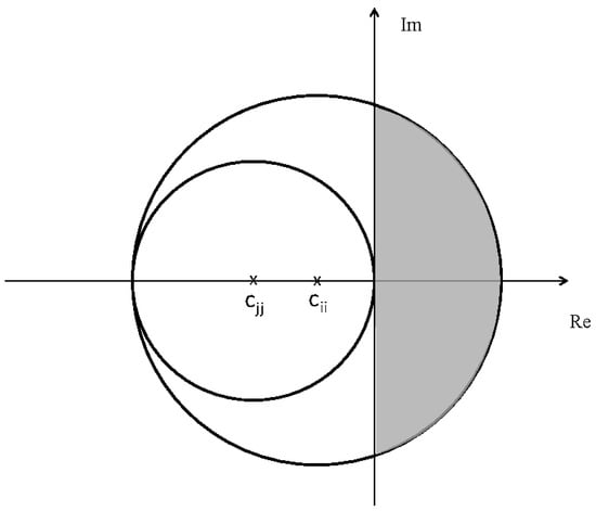
Figure 1.
Illustrative Gershgorin disks with a radius greater than the absolute value of the center.
Equations (2)–(4) provide the rules to construct a coupling matrix with some negative weights, depending on the values of the parameters u and v. It is important to note, on the one hand, that these values are chosen as connection weights; and on the other hand, that this represents a specific structure of a weighted coupling matrix. Nevertheless, many other configurations could be designed.
Remark 2.
It is important to emphasize that this algorithm produces a particular family of stable connectivity matrices. However, variations of the algorithm could be developed that still yield stable matrices.
2.1. Example of Mixed Connectivity Matrix
Now, in order to illustrate the method, consider the case for . Following Equations (2)–(4) the coupling matrix is then given as follows
for this example, there are two nodes negatively coupled, and the rest of the nodes are positively connected. The eigenvalues of this matrix are and , which clearly are negative and one is zero. The behavior of the eigenvalues for and are illustrated in Figure 2, where it is evident that one eigenvalue is equal to zero and the rest of the eigenvalues are in general negative, note that as the values of u and v increases the eigenvalues decrease.
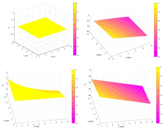
Figure 2.
Evolution of eigenvalues as a function of u and v for , then .
For , the eigenvalues are and , see Figure 3 and the behavior of the eigenvalues is again decreasing.
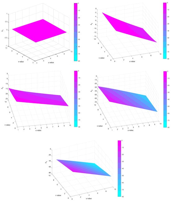
Figure 3.
Evolution of eigenvalues as a function of u and v for , then .
For , the eigenvalues are given by and . For , using numerical values for u and v, we find that all the eigenvalues of the matrix family C satisfy the property that one eigenvalue is zero and the rest are negative. In all cases, the eigenvalue behavior is similar, that is, the eigenvalues decrease as the values of v and u increase. Therefore, these matrices are suitable as connectivity matrices for studying the effects of negative couplings. Moreover, this behavior of the eigenvalues being monotonically decreasing with respect to u and v can be interpreted as allowing control over the coupling weights between nodes by adjusting these parameters. Finally, given this predictable behavior, one can select or fix specific values for u and v to investigate the resulting network dynamics.
2.2. Cases n = 2 and n = 3
We now consider the cases of Laplacian matrices of size and , assuming that D is symmetric, with off-diagonal elements given by and diagonal elements defined by , so that each row sums to zero. This construction guarantees that is an eigenvector associated with the zero eigenvalue, which reflects the common phase invariance in consensus or diffusion systems.
Case
n = 2
For , the Laplacian matrix has the general form:
where and is the sign of the coupling. The eigenvalues are .; now if (positive coupling), then : therefore the matrix is negative semidefinite, and the system converges to equilibrium (stable). But if (negative coupling), then the matrix has a positive eigenvalue, therefore it is not negative semidefinite, and the system is unstable.
This result shows that, in two-node networks, negative coupling does not induce stability, even though the matrix retains the zero-sum row property. Stability critically depends on the sign of the interaction; only positive coupling leads to stable dynamics.
Case
n = 3
For , we consider three binary interactions with positive intensities , and assign independent signs to each element outside the diagonal: , , , with . The diagonal elements are determined by balance . This construction generates different matrices.
Each of these matrices has at least one zero eigenvalue (associated with the vector ), as a consequence of the row sum being zero. For the system to be negative semidefinite (and therefore stable in the subspace orthogonal to ), all other eigenvalues must be non-positive.
A necessary criterion (although not sufficient in dimension 3 to guarantee negative semidefiniteness without further analysis) is that the leading minors alternate in sign or, at least, that the first two leading minors satisfy , , with at least one being strict, which suggests a spectral structure dominated by negative signs.
From the eight cases, only one induces at least one positive eigenvalue and therefore induces instability. In the remaining seven cases, the matrix exhibits alternating signs in the principal minors or a spectral structure compatible with negative semidefiniteness under certain conditions on .
The only exception is the case where , that is, when all elements outside the diagonal are negative. In this case
The minors:
Both minors are strictly positive, which implies that the matrix is not negative semidefinite. In fact, the spectrum includes at least one positive eigenvalue, which leads to dynamic instability.
This result is interesting while in the case negative coupling already breaks stability, in most configurations with mixed signs still allow stable or semi-stable structures, except when all interactions are negative. Therefore, for , only positive coupling induces stability; and for , there are 8 possible configurations of signs, of which 7 allow a spectral structure compatible with stability (negative semidefinite or with alternating minors), while the only configuration with all negative interactions does not satisfy being negative semidefinite and generates instability.
This suggests that, in coupling networks, the mere presence of negative interactions does not imply instability, as long as they are not dominant or consistent in sign. Stability is robust against mixtures of couplings, but is critically lost when all links are negative, which can be interpreted as a global repulsion that prevents the cohesion of the system.
In the next section, we present an application of these connectivity matrices in the synchronization of a network of chaotic systems and a Kuramoto model network.
3. Synchronization Examples
3.1. Chaos Synchronization of Networks
In order to support the theoretical construction presented and demonstrate its practical usefulness, a simulation based on a Lorenz system network is introduced below. This example shows how the proposed family of coupling matrices, which includes positive and negative weights, can achieve stable synchronization between the nodes of the system. In this case, the topology used corresponds to a fully connected network, and its structure is defined by the matrix (5). The network is composed of four identical dynamic systems; although the Lorenz system is used to illustrate the procedure, the approach is general and can be extended to other models and a major number of system in the network. The Lorenz system is given by
The system parameters are given by , , and . It is assumed that all states are measurable, meaning that the output signals correspond to the full state vector of each system, denoted by . It is well known that, with these parameter values, the Lorenz systems exhibit chaotic behavior. Therefore, we aim to achieve synchronous chaotic behavior among the systems in the network. The parameter differs between nodes, since is randomly selected from the interval , resulting in distinct dynamics for each system. The network equations are then given as in Equation (1) where, denotes the vector field of each system, which in this case is given by Equation (6). The matrix is the inner connection matrix that defines the interconnection channels between the systems. The coefficients are the entries of the coupling matrix given in Equation (5) with and and with network topology as in Figure 4. The values and were selected to obtain a spectrum with a zero eigenvalue and the remaining eigenvalues strictly negative, with a significant separation between them. This allows us to clearly observe the convergence of the system towards the synchronized regime, as well as to analyze the impact of different modes in the transient time.
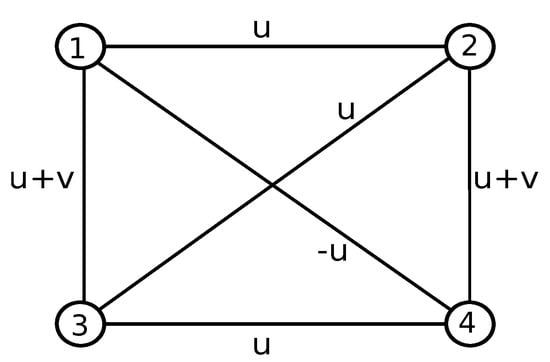
Figure 4.
Network with couplings positives and negatives used for synchronization of Lorenz systems.
According to the results in [], to achieve stability in the synchronization regime, the second largest eigenvalue of the matrix C must be less than or equal to a certain negative constant. By construction, the matrix C has one zero eigenvalue and three negative eigenvalues; therefore, the synchronization condition is satisfied.
Now, with this network configuration, the systems were initially unconnected, that is, they exhibited free behavior until time , when the interconnection was activated according to the connectivity matrix. The chosen values for v and u are such that the eigenvalues of the Laplacian signed coupling matrix C are , , , and . Figure 5 illustrates the synchronization of the network of Lorenz systems. As can be seen, synchronization is maintained despite the presence of negative coupling values. Moreover, the synchronization between systems is in-phase; therefore, the negative couplings do not induce anti-phase or unstable synchronization. Moreover, the spectral structure of the signed Laplacian matrix is by design that it has only one zero eigenvalue, and all others are negative. This guarantees that the modes transverse to the synchronization state are stable, as required by the master stability function criterion. The second largest eigenvalue, in particular, plays a key role, the more negative it is, the faster the synchronization process will be. In the numerical examples, values such as or indicate strong and robust convergence. Figure 5 illustrates the synchronization of chaotic Lorenz systems, whose individual dynamics present non-periodic trajectories that are sensitive to initial conditions. The convergence of the individual trajectories to common trajectories, even starting from different initial conditions, is evidence of chaotic in phase synchronization.
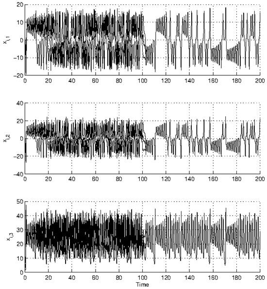
Figure 5.
Dynamic evolution of the synchronization of the systems in the network.
This result can be extended to networks with a larger number of nodes, since the criterion used to determine the connectivity matrix also holds for integers .
3.2. Phase Synchronization of Kuramoto Model with Attractive and Repulsive Couplings
In this subsection, complete phase synchronization is illustrated, even when the systems in the network are linked through both attractive and repulsive couplings. The Kuramoto model is used for this purpose, as follows:
For this example, a network with oscillators is considered, where denotes the oscillator, is its natural frequency chosen randomly, and . The 50 eigenvalues for and are plotted in Figure 6 and it can be observed that all eigenvalues are negative except .
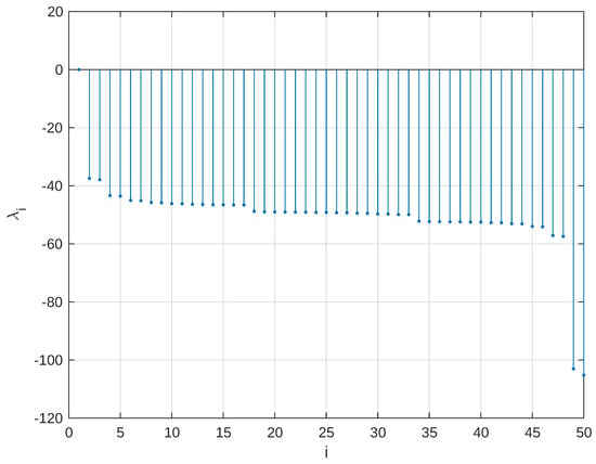
Figure 6.
Eigenvalues of the matrix C with , and .
In Figure 7 a color representation of the connectivity weights is illustrated. As can be seen, the negative couplings are regularly distributed throughout the matrix; that is, many nodes are connected through repulsive couplings. As shown in Figure 8 the phase error remains close to zero, where denotes the radius of a small ball. This indicates that the phases of the systems remain sufficiently close, and thus the systems are in phase synchronization. In other words, neither anti-phase nor unstable behavior is observed. On the other hand, Figure 6 shows the behavior of the spectrum as the size of the network increases. For N = 50 all the non zero eigenvalues are clearly located on the negative semi-axis of the real plane. No positive or complex values appear, which is a favorable sign, as it implies that the entire network is stable and can sustain a synchronized state. Furthermore, the distribution of these eigenvalues is not uniform, some are grouped near the origin (although not reaching zero), while others are further away. This could be interpreted as an indication that certain modes dampen quickly, while others require more time, which influences the duration of the transient regime prior to synchronization. An additional relevant aspect is the arrangement of negative connections in the matrix. Figure 7 shows that these do not appear randomly, but follow a structured and periodic pattern, which is a product of the designed algorithm. This organization prevents the appearance of frustrated loops or coupling configurations that hinder synchronization. In other words, the presence of repulsive links is not a problem if they are distributed appropriately.
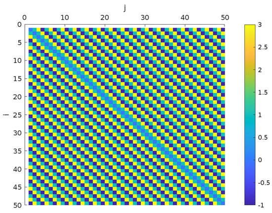
Figure 7.
Color distribution of matrix elements with , and , dark blue indicates negative coupling weight between i and j node.
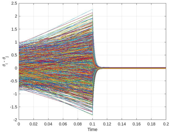
Figure 8.
Phase synchronization of the network, . The systems in the network were connected for .
These results demonstrate that the proposed family of coupling matrices can successfully achieve phase synchronization in networks of larger scale, even under mixed attractive and repulsive coupling.
4. Conclusions
In this proposal, an algorithm for designing connectivity matrices with both attractive and repulsive couplings that ensure the stability of synchronization in complex networks was presented. The algorithm structures the weights between connected nodes in such a way that the resulting Laplacian matrices satisfy essential spectral conditions: one zero eigenvalue and the rest strictly negative, thus supporting complete and in phase synchronization. The main result was formulated and proved as a constructive theorem, and its effectiveness was corroborated through numerical simulations involving Lorenz systems and Kuramoto oscillators; a key contribution of this method is that it allows the inclusion of negative weights preserving synchronization, provided that the weights are placed strategically. The adjustable parameters in the algorithm provides flexibility in the design of the spectral properties of the connectivity matrix, which is useful in applications where control over the dynamics of synchronization in networks is required. However, a possible limitation of the current approach is that the position of negative couplings is not arbitrary, that is, the weights must satisfy certain structural rules to preserve stability. Additionally, the method considers constant coupling values; thus, time varying or adaptive couplings remain an open problem for future research. This approach proposes a simple but powerful algorithm for modeling complex interconnected systems in which cooperative and antagonistic interactions coexist.
Author Contributions
Conceptualization, G.S.-P.; investigation and methodology, A.E.-V. and B.C.L.-O.; formal analysis, G.S.-P., J.R.; software, validation, J.R. and J.S.-E.; writing-original draft preparation, G.S.-P.; All authors have read and agreed to the published version of the manuscript.
Funding
This research received no external funding.
Data Availability Statement
The data that support the results reported are available from the corresponding author upon reasonable request.
Conflicts of Interest
The authors declare no conflict of interest.
References
- Watts, D.J.; Strogatz, S.H. Collective dynamics of ‘small-world’ networks. Nature 1998, 393, 440–442. [Google Scholar] [CrossRef] [PubMed]
- Albert, R.; Statistical, A.L. Statistical mechanics of complex networks. Rev. Mod. Phys. 2002, 74, 47–97. [Google Scholar] [CrossRef]
- Arenas, A.; Díaz-Guilera, A.; Kurths, J.; Moreno, Y.; Zhou, C. Synchronization in complex networks. Phys. Rep. 2008, 469, 93–153. [Google Scholar] [CrossRef]
- Strogatz, S.H. Exploring complex networks. Nature 2001, 410, 268–276. [Google Scholar] [CrossRef]
- Atay, F.M.; Biyikoglu, T. Graph operations and synchronization of complex networks. Phys. Rev. E 2005, 72, 016217. [Google Scholar] [CrossRef]
- Gómez-Gardeñes, J.; Moreno, Y.; Arenas, A. Explosive Synchronization Transitions in Scale-Free Networks. Phys. Rev. Lett. 2007, 98, 034101. [Google Scholar] [CrossRef]
- Guclu, H.; Korniss, G.; Novotny, M.A.; Toroczkai, Z.; Rácz, Z. Synchronization landscapes in small-world-connected computer networks. Phys. Rev. E 2006, 73, 066115. [Google Scholar] [CrossRef]
- Lerman, K.; Ghosh, R. Network Structure, Topology, and Dynamics in Generalized Models of Synchronization. Phys. Rev. E 2012, 86, 026108. [Google Scholar] [CrossRef]
- Zenga, X.; Hui, Q.; Haddad, W.M.; Hayakawa, T.; Bailey, J.M. Synchronization of biological neural network systems with stochastic perturbations and time delays. J. Frankl. Inst. 2014, 351, 1205–1225. [Google Scholar] [CrossRef]
- Salem, M.S.Z. Biological Networks: An Introductory Review. J. Proteom. Genom. Res. 2018, 2, 41–111. [Google Scholar] [CrossRef]
- Motter, A.E.; Myers, S.A.; Anghel, M.; Nishikawa, T. Spontaneous synchrony in power-grid networks. Nat. Phys. 2013, 9, 191–197. [Google Scholar] [CrossRef]
- Sajadi, A.; Kenyon, R.W.; Hodge, B.M. Synchronization in electric power networks with inherent heterogeneity up to 100% inverter-based renewable generation. Nat. Commun. 2022, 3, 2490. [Google Scholar] [CrossRef]
- Lopes, M.A.; Hamandi, K.; Zhang, J.; Creaser, J.L. The role of additive and diffusive coupling on the dynamics of neural populations. Sci. Rep. 2023, 13, 4115. [Google Scholar] [CrossRef] [PubMed]
- Chen, G.; Duan, Z. Introduction to Focus Issue: Synchronization in Complex Networks. Chaos 2008, 18, 037102. [Google Scholar] [CrossRef]
- Liu, X.; Chen, T.P. Synchronization analysis for nonlinearly-coupled complex networks with an asymmetrical coupling matrix. Phys. A 2008, 387, 4429–4439. [Google Scholar] [CrossRef]
- Lü, J.; Chen, G. A time-varying complex dynamical network model and its controlled synchronization criteria. IEEE Trans. Autom. Control 2005, 50, 841–846. [Google Scholar]
- Gray, R.T.; Robinson, P.A. Stability and structural constraints of random brain networks with excitatory and inhibitory neural populations. J. Comput. Neurosci. 2009, 27, 81–101. [Google Scholar] [CrossRef]
- Madar, D.; Dekel, E.; Bren, A.; Alon, U. Negative auto-regulation increases the input dynamic-range of the arabinose system of Escherichia coli. BMC Syst. Biol. 2011, 5, 111. [Google Scholar] [CrossRef]
- Narberhaus, F. Negative regulation of bacterial heat shock genes. Mol. Microbiol. 1999, 31, 1–8. [Google Scholar] [CrossRef]
- Sun, M.; Cheng, X.; Socolar, J.E.S. Causal structure of oscillations in gene regulatory networks: Boolean analysis of ordinary differential equation attractors. Chaos 2013, 23, 025104. [Google Scholar] [CrossRef]
- Leyva, I.; Sendina-Nadal, I.; Almendral, J.A.; Sanjuán, M.A.F. Sparse repulsive coupling enhances synchronization in complex networks. Phys. Rev. E 2006, 74, 056112. [Google Scholar] [CrossRef]
- Yuan, D.; Tian, J.L.; Lin, F.; Ma, D.W.; Zhang, J.; Cui, H.T.; Xiao, Y. Periodic synchronization in a system of coupled phase oscillators with attractive and repulsive interactions. Front. Phys. 2018, 13, 130504. [Google Scholar] [CrossRef]
- Sharma, A. Explosive synchronization through attractive-repulsive coupling. Chaos Solitons Fractals 2021, 145, 110815. [Google Scholar] [CrossRef]
- Wang, Z.; Parastesh, F.; Rajagopal, K.; Hamarash, I.I.; Hussain, I. Delay-induced synchronization in two coupled chaotic memristive Hopfield neural networks. Chaos Solitons Fractals 2020, 134, 109702. [Google Scholar] [CrossRef]
- Antal, T.; Krapivsky, P.L.; Redner, S. Social balance on networks: The dynamics of friendship and enmity. Phys. D. 2006, 224, 130–136. [Google Scholar] [CrossRef]
- Wilson, H.R.; Cowan, J.D. Excitatory and Inhibitory interactions in localized population of model neurons. Biophys. J. 1972, 12, 1–24. [Google Scholar] [CrossRef]
- Kang, J.; Ramadoss, J.; Wang, Z.; Ali, A.M.A. Complete synchronization analysis of neocortical network model. Eur. Phys. J. Spec. Top. 2022, 231, 4037–4048. [Google Scholar] [CrossRef]
- Zanette, D.H. Synchronization and frustration in oscillator networks with attractive and repulsive interactions. Europhys. Lett. 2005, 72, 190–196. [Google Scholar] [CrossRef]
- Sadeh, S.; Clopath, C. Excitatory-inhibitory balance modulates the formation and dynamics of neuronal assemblies in cortical networks. Sci. Adv. 2021, 7, eabg8411. [Google Scholar] [CrossRef]
- Mackwood, O.; Naumann, L.B.; Sprekeler, H. Learning excitatory-inhibitory neuronal assemblies in recurrent networks. eLife 2021, 10, e59715. [Google Scholar] [CrossRef]
- Mosheiff, N.; Ermentrout, B.; Huang, C. Chaotic dynamics in spatially distributed neuronal networks generate population-wide shared variability. PLoS Comput. Biol. 2023, 19, e1010843. [Google Scholar] [CrossRef]
- Wang, Y.; Sun, Z.; Liu, S.; Zhou, Y.; Xu, W. Dynamic Survivability in Nonlinear Oscillation Systems with Attractive–Repulsive Interaction. Int. J. Bifurc. Chaos 2023, 33, 2350049. [Google Scholar] [CrossRef]
- Belardo, F.; Simić, S.K. On the Laplacian coefficients of signed graphs. Linear Algebra Its Appl. 2015, 475, 94–113. [Google Scholar] [CrossRef]
- Shepelev, I.A.; Muni, S.S.; Schöll, E.; Strelkova, G.I. Repulsive inter-layer coupling induces anti-phase synchronization. Chaos 2021, 31, 063116-1–063116-11. [Google Scholar] [CrossRef] [PubMed]
- Vathakkattil Joseph, G.; Pakrashi, V. Limits on Anti-Phase Synchronization in Oscillator Networks. Sci. Rep. 2020, 10, 10178. [Google Scholar] [CrossRef]
- Bronski, J.C.; De Ville, L. Spectral Theory for Dynamics on Graphs Containing Attractive and Repulsive Interactions. SIAM J. Appl. Math. 2014, 74, 83–105. [Google Scholar] [CrossRef]
- Chung, F.R.K. Spectral Graph Theory; Number 92; American Mathematical Society: Providence, RI, USA, 1997. [Google Scholar]
- Steur, E.; Michiels, W.; Huijberts, H.; Nijmeijer, H. Networks of diffusively time-delay coupled systems: Conditions for synchronization and its relation to the network topology. Phys. D 2014, 277, 22–39. [Google Scholar] [CrossRef]
- Montenbruck, J.M.; Schmidt, G.S.; Seyboth, G.S.; Allgöwer, F. On the Necessity of Diffusive Couplings in Linear Synchronization Problems with Quadratic Cost. IEEE Trans. Autom. Control 2015, 60, 3029–3034. [Google Scholar] [CrossRef]
- Wang, X.F.; Chen, G. Synchronization in scale-free dynamical networks: Robustness and fragility. IEEE Trans. Circuits Syst. I 2002, 49, 54–62. [Google Scholar] [CrossRef]
- Wang, X.F.; Chen, G. Synchronization in small-world dynami-cal networks. Int. J. Bifurc. Chaos 2002, 12, 187–192. [Google Scholar] [CrossRef]
- Wang, X.F.; Chen, G. Complex networks: Small-world, scale-freeand beyond. IEEE Circuits Syst. Mag. 2003, 3, 6–20. [Google Scholar] [CrossRef]
Disclaimer/Publisher’s Note: The statements, opinions and data contained in all publications are solely those of the individual author(s) and contributor(s) and not of MDPI and/or the editor(s). MDPI and/or the editor(s) disclaim responsibility for any injury to people or property resulting from any ideas, methods, instructions or products referred to in the content. |
© 2025 by the authors. Licensee MDPI, Basel, Switzerland. This article is an open access article distributed under the terms and conditions of the Creative Commons Attribution (CC BY) license (https://creativecommons.org/licenses/by/4.0/).