Abstract
Wireless power transfer (WPT) systems have ushered in a new era for wearable and implantable technologies, introducing opportunities for enhanced device functionality. A pivotal aspect in improving these devices is the optimization of electromagnetic transmission. This paper presents several solutions to improve electromagnetic transmission to an implantable/wearable device. Several scatterers are considered to mimic objects that can be easily worn by a patient, such as necklaces and bracelets, or easily integrated into textile fabric. An analytical method is employed to address the scattering by cylindrical objects above a biological tissue, modeled as a multilayer. Expansions into cylindrical waves, also represented through plane-wave spectra, are used to express the scattered fields in each medium. Numerical results for both the case of conducting and of dielectric cylindrical scatterers are presented at a frequency of the Industrial, Scientific and Medical band ( GHz), showing possible configurations of worn objects for electromagnetic field intensification.
Keywords:
electromagnetic scattering; implantable/wearable antennas; wireless power transfer systems MSC:
94-10; 92-10
1. Introduction
The evolution of Wireless Power Transfer (WPT) has revolutionized the world of wearable and implantable technologies. These devices, of increasing impact in our daily lives, demand a reliable and efficient source of power to operate optimally. One of the fundamental pillars for improving the performance of such devices is the optimization of electromagnetic transmission [1,2,3,4,5]. Amplifying the electromagnetic field intensity can be advantageous in various contexts. In wearable devices, more powerful transmission allows for more stable connectivity of the wireless link with other equipment or networks. Furthermore, the increased received energy can significantly extend the battery life of devices, reducing the need for frequent recharges. In the context of implantable devices, such as pacemakers, defibrillators, and medical sensors, enhanced electromagnetic transmission can ensure a constant connection between the device and the external control system, enabling real-time monitoring of the patient’s health. This is crucial for the timely detection of anomalies and the administration of preventive care, as outlined in [6,7,8], where several opportunities and challenges in microwave medical applications are detailed. Additional relevant applications are addressed in [9,10], where the analysis of wireless sensing healthcare systems is presented. Other applications can be found in geoscience, where the use of a passive scattering layer atop the ground can increase the electromagnetic interaction with buried objects. In this direction, in [11], a procedure of “unlocking” the ground by depositing a thin passive layer of conventional material atop of it was examined.
A recent study [12] presents an analytical model for the enhanced transmission of electromagnetic fields within a wireless power transfer system to wearable devices. This model relies on the scattering phenomenon of a plane-wave by a set of dielectric cylindrical scatterers aligned above a multilayer. The analytical approach allows the determination of the field scattered by the cylinders within each medium through expansions into cylindrical waves expressed in terms of plane-wave spectra. In [13,14], the scattering of a far-field source by perfectly conducting cylindrical scatterers positioned above a semi-infinite lossy medium is examined. The electromagnetic scattering problem is addressed using an analytical solution known as the “Cylindrical Wave Approach (CWA)” [15,16]. The interaction between a plane-wave field and the cylindrical scatterers is described through expansions into cylindrical waves, and a spectral method is employed to analyze the interaction between the scattered field and the interface.
Here, the theory is recalled and developed for the case of conducting cylinders placed above a multilayer. Numerical results are presented for both dielectric and conducting scatterers. In particular, several configurations are analyzed in which alignments of dielectric or conducting circular cross-section scatterers are designed to be placed on textile fabrics worn by individuals or patients, with the aim of increasing power transfer to wearable or implantable devices. The first configuration, called ‘Case A’, consists of an array of dielectric cylinders placed above a multilayer that models a layer of skin, fat, muscle, and a layer that simulates a generic antenna substrate. Our interest lies in analyzing electromagnetic transmission to an implantable antenna. In this case, an incident wave having the electric field directed along the cylinder axis (TM polarization) is considered at a frequency of GHz. An increase larger than 6 dB is observed in the electric field in the regions immediately above the antenna substrate. A second configuration, called ‘Case B’, consists of an array of dielectric cylinders placed above a multilayer that models biological tissues, including a layer simulating a tumor inclusion. We are interested in evaluating the field in the proximity of the tumor tissue.
The third configuration, called ‘Case C’, involves an array of conducting cylinders placed above a matching layer positioned between the scatterers and the biological tissues, showing how it is possible to obtain an intensification between the skin and fat layers, which may be of interest for an implantable receiving antenna. The fourth configuration, called ‘Case D’, involves an array of conducting cylinders positioned above a multilayer structure that mimics a textile layer followed by skin, fat, and muscle. The receiving antenna is positioned at the center of a textile layer immediately above the skin tissue, and an incident wave with the magnetic field aligned along the cylinder axis (TE polarization) is considered at a frequency of GHz. An enhancement factor exceeding 3 dB is observed for the electric field within regions situated in the middle of the textile layer.
2. Geometry of the Scattering Problem and Theoretical Analysis
We examine the geometry of the scattering scenario depicted in Figure 1. N cylindrical dielectric or conducting rods with circular cross-sections are positioned on the top of a multilayered structure. The structure extends infinitely along the y-axis. We analyze a layout with a multilayer embedded between two dielectric half-spaces, namely, medium 0 and medium M. Medium 0 is occupied by the vacuum with permittivity , while the media from 1 to M are linear, isotropic, and homogenous media having permittivity () and conductivity . The j-th layer () has a thickness of . Within medium 0, N scatterers are positioned along the y-axis. We consider a primary reference frame () with normalized coordinates and , where represents the vacuum wavenumber. Additionally, N local reference frames, centered on the axis of the t-th cylinder, are introduced. These frames utilize both Cartesian () and polar () coordinates, where , , and .
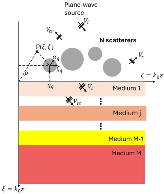
Figure 1.
Geometry of the scattering problem.
A plane-wave is the source of the scattering problem, propagating in medium 0, and propagates impinging on the multilayer. A scalar function ) is used to describe the y-directed electric field E, in the case of polarization, or the y-directed magnetic field H, in the one. In medium 0, the total field is decomposed as follows:
- : plane-wave incident field;
- : plane-wave reflected field, excited by reflection of the incident field onto the layered half-space ;
- : scattered field by the cylinders;
- : scattered-reflected field, excited by reflection of the scattered field onto the layered half-space ;
In the half-space , the following terms are considered:
- : plane-wave transmitted field, excited by the transmission of the incident field into layered media;
- : scattered-transmitted, excited by transmission of the scattered field into layered media.
Here, the analytical approach presented for dielectric cylinders in [12] is considered and extended for the case of conducting cylinders. The expression of the plane wave spectrum of a generic cylindrical function of order m is:
where is the angular spectrum of a cylindrical function, having explicit expression:
The scattered field has the following expression in polar coordinates, where the addition theorem of Hankel functions has been applied:
where is the m-th order cylindrical function defined in Equation (1), which here may be expressed, alternatively, through:
with a first-kind Hankel function, and an angular term.
Reflected cylindrical waves of m-th order, , are employed as basis functions of the scattered-reflected field :
If we consider N conducting scatterers in the layout of Figure 1, the unknown scattered fields are obtained by imposing the boundary conditions at the cylinders’ interface, for and polarizations, respectively:
After some algebra, it is possible to derive a linear system in the unknown coefficients :
where the coefficients and have the following expression:
and
where is the incident angle, , and .
For the applications addressed in this paper, we are interested in calculating the transmitted field within the multilayer. It is possible to obtain the field in the j-th medium () through an expansion into cylindrical TM waves, which have the following expression:
with and .
The amplitudes of the transmitted and reflected waves in each medium, and , are calculated using the approach presented in [12], that gives the interaction of a plane wave with a multilayer.
The analytical approach is implemented in a numerical code. The numerical computation of the spectral integrals associated with cylindrical functions is conducted in Matlab, implementing a truncation on the order p of the cylindrical waves through a criterion grounded on the characteristics of the Hankel functions [17]. The integrals are solved in Matlab, using the function integral that performs global adaptive quadrature [18]. The absolute tolerance is set to , considering an impinging wave of normalized amplitude. The infinite series are truncated between and with the rule , where is the normalized radius of the largest cylinder [17].
3. Numerical Results
3.1. Dielectric Scatterers
In this subsection, the possibility of realizing a dielectric layer to increase transmission within biological tissues is investigated, evaluating both a continuous layer and its discretization/approximation by means of circular dielectric cylinders. Compared to the continuous case, it is evaluated that the use of circular cylinders rather than a single dielectric layer presents an improvement in transmission, as will be demonstrated in subsequent case studies.
3.1.1. Case A: Layout with an Implanted Antenna
As a first case study, we analyze the configuration shown in Figure 2. N circular dielectric scatterers are placed above a multilayered medium modeling a -thick layer of skin, a -thick layer of fat, a -thick layer of muscle, a -thick layer simulating a generic antenna substrate, and a semi-infinite medium of muscle. We are, in fact, interested in analyzing the electromagnetic transmission to an implantable antenna. The dielectric parameters of the layers at the frequency of interest [19,20,21] are summarized in Table 1.
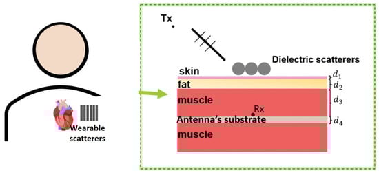
Figure 2.
Geometry of the scattering problem in a WPT system.

Table 1.
Dielectric parameters of the layers at GHz.
The analytical approach for the case of dielectric cylinders has been validated in [12].
Here, we conducted a preliminary study using the commercial electromagnetic simulator CST Microwave Studio to investigate and optimize the case where a periodic array of cylindrical scatterers lies on a multilayer structure. The cylinders have dielectric constant . The unit cell is simulated to study the reflection coefficient in the case of TM polarization (incident electric field directed along the cylinder axis) and TE polarization (magnetic field directed along the cylinder axis). The thicknesses of the layers are assumed as follows: mm, mm, mm, and mm. Figure 3a shows the reflection coefficient as a function of the scatterer diameter for both polarizations. The analyzed unit cell is shown in the insert. The reflection coefficient in the case where the scatterer has a rectangular shape (continuous case) is shown in Figure 3b for TM and TE polarization. It can be seen that a better transmission is obtained in the case of the circular scatterer.
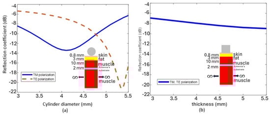
Figure 3.
Reflection coefficient for TM and TE polarization for: (a) cylindrical scatterer and (b) unit cell with rectangular scatterer (continuous case).
Therefore, the following cases will use this single configuration with circular cross-section cylinders on which parametric analyses were performed by varying the number of cylinders, radii, and cylinder spacing (center to center gap).
As a second step, a finite number of cylindrical scatterers is considered, as shown in Figure 4, where dielectric cylinders of radius , , and spaced by a gap are positioned above the multilayer with the same configuration illustrated in Figure 2. Figure 5a shows the magnitude of the electric field evaluated at mm as the radius of the scatterers changes and for several gap configurations obtained with the present analytical approach. It can be observed that the maximum electric field value is obtained for the ‘no gap configuration’. For this configuration, the horizontal electric field profile along the z-direction at mm is shown in Figure 5b for several radius values. An intensification around 6 dB is observed in the case where the cylinders have radius mm. This is also clearly visible in Figure 6, where the electric field map is shown in (a) and the vertical field profile along the entire multilayer is shown in (b). At the interface between the muscle and the antenna substrate, the intensification is evident.
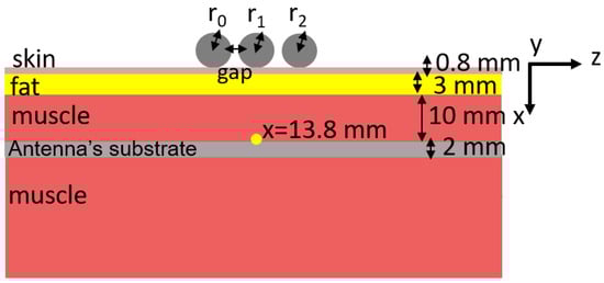
Figure 4.
Configuration with dielectric cylindrical scatterers of radius , , and and spaced by a gap. The thicknesses of the layers are: mm, mm, mm, mm.
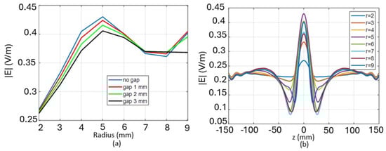
Figure 5.
(a) Magnitude of the electric field evaluated at mm as the radius of the scatterer varies and for different gap values; (b) Horizontal profile of the electric field along z at mm for several radius values.
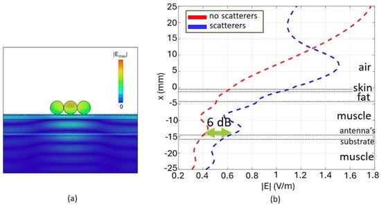
Figure 6.
(a) Electric field map (b) Vertical profile of the electric field along the multilayer structure. Comparison between the case where scatterers are present and the case where they are absent.
Configurations with an increased number of scatterers are considered as illustrated in Figure 7, where the comparison between the case where scatterers are present and the case where they are absent is presented. In particular, in Figure 7b–d, the horizontal profile of the electric field at mm is shown. In the case where the number of scatterers is , two peaks of the electric field are observed, while in the case where , we observe three different peaks.
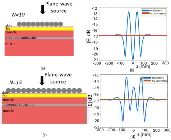
Figure 7.
Configurations in which an increased number of cylindrical scatterers are considered: (a) , (c) . (b,d) show the horizontal profile of the electric field at mm, for the two configurations, respectively.
3.1.2. Case B: Layout with Tumor Inclusion
As a second case study, we analyze the configuration shown in Figure 8, Figure 9, Figure 10 and Figure 11. N circular dielectric scatterers, with equal radii, are placed above a multilayered medium modeling a -thick layer of skin, a -thick layer of fat, a -thick layer of muscle, a h-thick layer simulating a tumor inclusion, and a semi-infinite medium of muscle. The tumor tissue has a dielectric constant of and a at GHz [22]. A TM polarization of the incident field is considered. Figure 9 shows the vertical profile of the electric field, in the presence or absence of the cylindrical scatterers, along the multilayer in the middle of the structure. The horizontal profile of the electric field at mm, just above the tumor inclusion, is shown in Figure 10a, while the modal configuration of the electric field is shown in Figure 10b. In Figure 11, a configuration with a reduced number of cylinders, in particular , is considered. Figure 12 shows the vertical profile of the electric field along the structure. Comparison between the case where scatterers are present and the case where they are absent is shown. The horizontal profile, where the intensification obtained can be observed, is shown in Figure 13a. Figure 13b shows the electric field map at the frequency of interest.
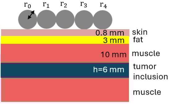
Figure 8.
Configuration with dielectric cylinders (), with the same radii ( mm), positioned above a layer of skin, fat, muscle, and a layer mimicking a tumor inclusion (of thickness mm).
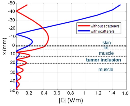
Figure 9.
Vertical profile of the electric field along the multilayer structure. Comparison between the case where scatterers are present and the case where they are absent for the configuration of Figure 8.
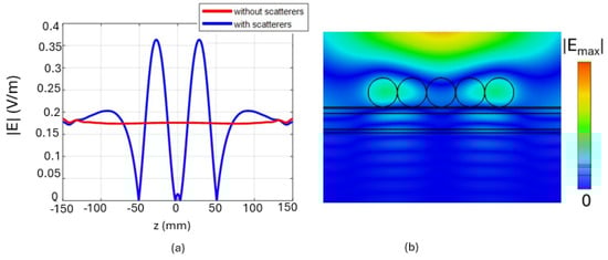
Figure 10.
(a) Horizontal profile of the electric field at mm for the configuration of Figure 8; (b) Electric field map at GHz.
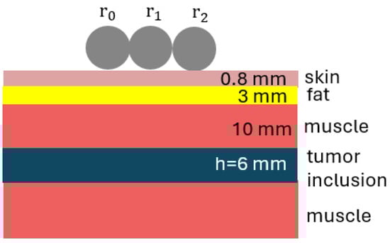
Figure 11.
Configuration with dielectric cylinders (), with the same radii ( mm), positioned above a layer of skin, fat, muscle, and a layer mimicking a tumoral inclusion (of thickness mm).
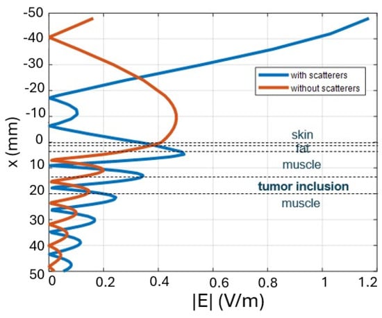
Figure 12.
Vertical profile of the electric field along the multilayer structure. Comparison between the case where scatterers are present and the case where they are absent for the configuration of Figure 11.
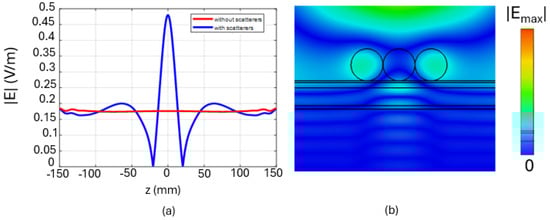
Figure 13.
(a) Horizontal profile of the electric field at mm for the configuration of Figure 11; (b) Electric field map at GHz.
3.2. Conducting Scatterers
In this subsection, we investigate the possibility of using conducting cylinders, again with the aim of intensifying electromagnetic transmission to a possible implantable or wearable antenna. For conductors, wires must be considered here to allow transmission at least in a polarized state. Their use has been considered either by placing an adapter layer underneath the array (‘Case C’) or considered isolated (‘Case D’). Compared to the case of dielectric cylinders, the intensification is obtained only in the TE case.
First, a validation of the analytical method presented in Section 2 is shown, either for the case of a single conducting cylinder positioned above a multilayer consisting of skin (thickness mm), fat (thickness 20 mm), and muscle and a case of cylinders. TE polarization is considered for both cases. The incident plane wave has an amplitude of |H| = 1 A/m, and normally impinges on the interface. Specifically, in Figure 14a, the horizontal profile of the magnetic field at mm is shown for the case of a single cylinder of radius 30 mm. The distance from the edge of the cylinder to the surface of the skin is 5 mm and it is positioned in . Figure 14b shows the vertical profile of the magnetic field along the multilayer structure at the centre of symmetry (). A case of scattering by cylinders above the multilayer is simulated, with cylinders of equal radii of 30 mm, and aligned horizontally in mm, with distance between centers of 100 mm. The horizontal profile of the magnetic field at mm is shown in Figure 15a. Figure 15b shows the vertical profile of the magnetic field along the multilayer. The results obtained with our analytical method are compared with those simulated with the commercial electromagnetic simulator CST Microwave Studio, showing a good agreement. In our method, the domain is unlimited, whereas with CST, we consider a finite domain in x and z enclosed by a PML (Perfect Matching Layer)-type boundary. In the truncation of the numerical implementation of the CWA, in (7) was considered in both cases.
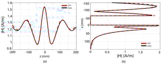
Figure 14.
Comparison between the analytical method CWA and CST: (a) Horizontal profile of the magnetic field at a depth of mm; (b) vertical profile of the magnetic field along the multilayer, mm.
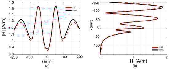
Figure 15.
Comparison between the analytical method CWA and CST: (a) Horizontal profile of the magnetic field at a depth of mm; (b) vertical profile of the magnetic field along the multilayer, mm.
3.2.1. Case C: Layout with Conducting Cylinders and a Matching Layer
A different case is considered for N metallic cylinders (perfectly electric conductor, PEC) placed above the multilayer shown in Figure 16. A textile layer of thickness , a skin layer of thickness and a fat layer of thickness are considered. A receiving antenna is assumed to be positioned in the middle of the skin layer.
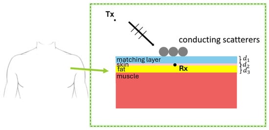
Figure 16.
N metallic cylinders (perfectly electric conductor, PEC) placed above the multilayer.
Also in this case, as described in Section 3.1 for the dielectric scatterers, we conducted a preliminary study to optimize a periodic array of PEC scatterers whose unit cell is shown in Figure 17a. The unit cell consists of a layer, for now called a ‘matching layer’, of thickness mm and dielectric constant , a layer of skin ( mm), a layer of fat ( mm), and a semi-infinite layer of muscle. Figure 17b shows a parametric study on the dielectric constant of the matching layer between the scatterers and the skin. Around the frequency of GHz, the best solution is obtained for a dielectric constant of . Therefore, considering this permittivity value, in Figure 18a, the reflection coefficient of the analyzed unit cell is reported in the case where both the scatterer and the matching layer are present and in the case where both are absent. Figure 18b shows the vertical profile of the electric field along the multilayer. At the interface between skin and fat, we observe an intensification of 3.3 dB.
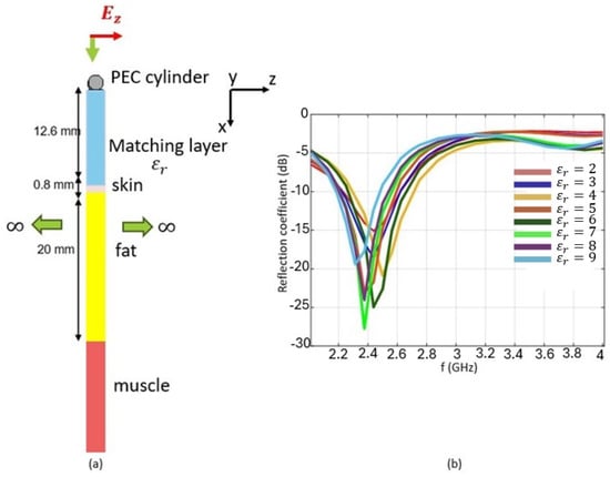
Figure 17.
(a) Unit cell with PEC scatterer placed above the multilayer; (b) Reflection coefficient as a function of the dielectric constant of the matching layer.
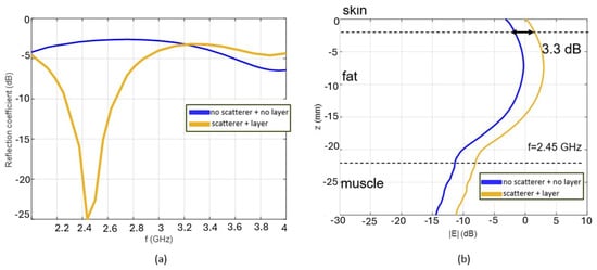
Figure 18.
Reflection coefficient of the unit cell. (a) Comparison between no scatterer + no layer and scatterer + layer configurations; (b) Vertical profile of the electric field along the multilayer at GHz.
Subsequently, the case with a finite number N of conducting cylinders, shown in Figure 19, was analyzed. N conductor cylinders lie on the same multilayer configuration shown in Figure 17a. Figure 19b shows the horizontal profile of the electric field in the middle of the skin layer evaluated for scatterers.
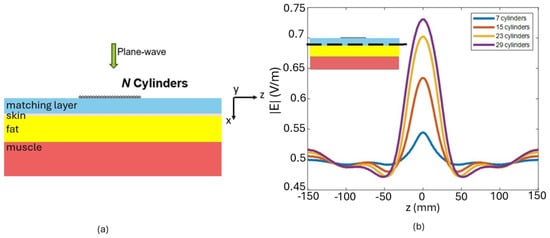
Figure 19.
(a) Configuration with N conducting cylindrical scatterers; (b) Horizontal profile of the electric field in the middle of the skin layer at GHz, for .
3.2.2. Case D: Layout with Conducting Cylinders without a Matching Layer
As a final study, a configuration with conducting cylindrical scatterers is considered. They are placed above a layer of cotton with dielectric constant , skin, fat, and muscle. The thicknesses are mm, mm, mm (Figure 20). The permittivity values are the same as those used in previous cases. The outer cylinders have radius mm and the inner one has a radius of mm. In this case, we are interested in observing what happens in mid-cotton, where, for example, a wearable antenna could be placed. Figure 21a shows the horizontal profile of the magnetic field in the middle of the cotton layer in the case where the scatterers are present and absent. Figure 21b shows the vertical profile of the magnetic field along the multilayer. Also, in this case, an intensification of 3 dB is observed.
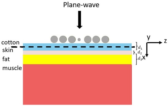
Figure 20.
Configuration with conducting cylindrical scatterers placed above a layer of cotton (), skin, fat, and muscle ( mm, mm, mm). Outer cylinders have radius mm; the inner one has a radius of mm.
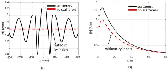
Figure 21.
(a) Horizontal profile of the magnetic field in the middle of the cotton layer; (b) Horizontal profile of the electric field in the middle of the skin layer at GHz.
Dielectric or conducting scatterers can then be strategically arranged to create a matching structure that enhances the electromagnetic field in regions beneath them. Dielectric cylinders, which are insulating materials, can be custom-designed to create an array that effectively acts as a lens, focusing and intensifying the electromagnetic field in the desired region beneath the layer. Conducting cylinders, on the other hand, can reflect and guide electromagnetic waves due to their high conductivity. When these cylinders are organized in a specific configuration, they can create constructive interference patterns that increase the field under the matching layer. Both approaches rely on the careful design and arrangement of cylinders to achieve the desired field intensification. This effect is dependent on the polarization of the incident field.
4. Conclusions
The advent of Wireless Power Transfer (WPT) systems has initiated a transformative phase for wearable and implantable technologies, unlocking possibilities for advanced device functionalities. To optimize these innovations, enhancing electromagnetic transmission stands as a critical factor. This study introduces a range of solutions aimed at elevating electromagnetic transmission to wearable and implantable devices. Notably, it addresses the intricate challenge of electromagnetic scattering caused by an array of dielectric or conducting cylinders positioned over a multilayer medium. These simulated scatterers emulate everyday items, such as necklaces, bracelets, or seamlessly integrated textile components, potentially worn by patients. Employing an analytical approach, the study achieves the exact solution for the scattered field by these cylinders within each medium, utilizing expansions into cylindrical waves expressed through plane-wave spectra. The multilayer model, designed to represent biological tissues, provides a comprehensive framework for analysis. Numerical outcomes, encompassing both conducting and dielectric cylindrical scatterers operating at the Industrial, Scientific, and Medical (ISM) band frequency of 2.45 GHz, offer valuable insights into the practical implementation of these findings. The method presented can be useful also for complementary cases in which a protection against excessive field intensities inside human tissues should be considered. This will be considered in a forthcoming paper.
Author Contributions
Conceptualization, L.T., C.P. and G.S.; Methodology, L.T., C.P. and G.S.; Validation, L.T., C.P. and G.S. All authors have read and agreed to the published version of the manuscript.
Funding
This work was funded in part by the Italian Ministry for Education, University, and Research through the project PRIN2017 “Wireless Power Transfer for Wearable and Implantable Devicess (WPT4WID)” under Grant 2017YJE9XK.
Data Availability Statement
The data will be made available by the authors on request.
Conflicts of Interest
The authors declare no conflict of interest.
References
- Genovesi, S.; Butterworth, I.R.; Serrallès, J.E.C.; Daniel, L. Metasurface matching layers for enhanced electric field penetration into the human body. IEEE Access 2020, 8, 197745–197756. [Google Scholar] [CrossRef]
- Gasperini, D.; Costa, F.; Daniel, L.; Manara, G.; Genovesi, S. Matching layer design for far-field penetration into a multilayered lossy media. IEEE Antennas Propag. Mag. 2022, 64, 86–96. [Google Scholar] [CrossRef]
- Kiourti, A.; Abbosh, A.M.; Athanasiou, M.; Björninen, T.; Eid, A.; Furse, C.; Ito, K.; Lazzi, G.; Manoufali, M.; Pastorino, M.; et al. Next-generation healthcare: Enabling technologies for emerging biolectromagnetics applications. IEEE Open J. Antennas Propag. 2022, 3, 363–390. [Google Scholar] [CrossRef]
- Basir, A.; Cho, Y.; Shah, I.A.; Hayat, S.; Ullah, S.; Zada, M.; Shah, S.A.A.; Yoo, H. Implantable and Ingestible Antenna Systems: From imagination to realization [Bioelectromagnetics]. IEEE Antennas Propag. Mag. 2023, 65, 70–83. [Google Scholar] [CrossRef]
- Costanzo, A.; Apollonio, F.; Baccarelli, P.; Barbiroli, M.; Benassi, F.; Bozzi, M.; Burghignoli, P.; Campi, T.; Cruciani, S.; Di Meo, S.; et al. Wireless power transfer for wearable and implantable devices: A review focusing on the WPT4WID research project of national relevance. In Proceedings of the 2021 XXXIVth General Assembly and Scientific Symposium of the International Union of Radio Science (URSI GASS), Rome, Italy, 28 August–4 September 2021. [Google Scholar]
- Chandra, R.; Zhou, H.; Balasingham, I.; Narayanan, R.M. On the opportunities and challenges in microwave medical sensing and imaging. IEEE Trans. Biomed. Eng. 2015, 62, 1667–1682. [Google Scholar] [CrossRef] [PubMed]
- Selvi, C.; Subramaninan, R.; Yogeswari, M.; Subhasini, B.; Priya, G. Role of wireless wearable technologies in recent advancements. In Proceedings of the 2021 Third International Conference on Intelligent Communication Technologies and Virtual Mobile Networks (ICICV), Tirunelveli, India, 4–6 February 2021; pp. 1167–1171. [Google Scholar]
- Paolucci, T.; Pezzi, L.; Centra, A.M.; Giannandrea, N.; Bellomo, R.G.; Saggini, R. Electromagnetic field therapy: A rehabilitative perspective in the management of musculoskeletal pain—A systematic review. J. Pain Res. 2020, 13, 1385–1400. [Google Scholar] [CrossRef] [PubMed]
- Huang, H.; Gong, T.; Ye, N.; Wang, R.; Dou, Y. Private and secured medical data transmission and analysis for wireless sensing healthcare system. IEEE Trans. Ind. Inform. 2017, 13, 1227–1237. [Google Scholar] [CrossRef]
- Cameron, T.; Loeb, G.; Peck, R.; Schulman, J.; Strojnik, P.; Troyk, P. Micromodular implants to provide electrical stimulation of paralyzed muscles and limbs. IEEE Trans. Biomed. Eng. 1997, 44, 781–790. [Google Scholar] [CrossRef] [PubMed]
- Valagiannopoulos, C.A.; Tsitsas, N.L.; Sihvola, A.H. “Unlocking” the ground: Increasing the detectability of buried objects by depositing passive superstrate. IEEE Trans. Geosci. Remote Sens. 2016, 54, 3697–3709. [Google Scholar] [CrossRef]
- Tognolatti, L.; Ponti, C.; Schettini, G. Use of a set of wearable dielectric scatterers to improve electromagnetic transmission for a body power transfer system. IEEE J. Electromagn. RF Microwaves Med. Biol. 2022, 6, 280–286. [Google Scholar] [CrossRef]
- Ponti, C.; Tognolatti, L.; Schettini, G. Electromagnetic scattering by metallic targets above a biological medium with spectral-domain approach. IEEE Open J. Antennas Propag. 2021, 2, 230–237. [Google Scholar] [CrossRef]
- Tognolatti, L.; Ponti, C.; Schettini, G. A Practical Solution to Enhance Electromagnetic Transmission to an Implantable/Wearable Antenna. In Proceedings of the 2022 16th European Conference on Antennas and Propagation (EuCAP), Madrid, Spain, 27 March–1 April 2022; pp. 1–3. [Google Scholar]
- Borghi, R.; Schettini, G.; Santarsiero, M. Numerical study of the reflection of cylindrical waves of arbitrary order by a generic planar interface. J. Electromagn. Waves Appl. 1999, 13, 27–50. [Google Scholar] [CrossRef]
- Borghi, R.; Gori, F.; Santarsiero, M.; Frezza, F.; Schettini, G. Plane-wave scattering by a perfectly conducting cylinder near a plane surface: Cylindrical-wave approach. J. Opt. Soc. Am. A 1996, 13, 483–493. [Google Scholar] [CrossRef]
- Elsherbeni, A.Z. A comparative study of two-dimensional multiple scattering techniques. Radio Sci. 1994, 29, 1023–1033. [Google Scholar] [CrossRef]
- Shampine, L.F. Vectorized adaptive quadrature in MATLAB. J. Comput. Appl. Math. 2008, 211, 131–140. [Google Scholar] [CrossRef]
- Gabriel, S.; Lau, R.W.; Gabriel, C. The dielectric properties of biological tissues: I. literature survey. Phys. Med. Biol. 1996, 41, 2231. [Google Scholar] [CrossRef] [PubMed]
- Gabriel, S.; Lau, R.W.; Gabriel, C. The dielectric properties of biological tissues: II. Measurements in the frequency range 10 Hz to 20 GHz. Phys. Med. Biol. 1996, 41, 2251. [Google Scholar] [CrossRef]
- Gabriel, S.; Lau, R.W.; Gabriel, C. The dielectric properties of biological tissues: III. Parametric models for the dielectric spectrum of tissues. Phys. Med. Biol. 1996, 41, 2271. [Google Scholar] [CrossRef]
- Lazebnik, M.; Popovic, D.; McCartney, L.; Watkins, C.B.; Lindstrom, M.J.; Harter, J.; Sewall, S.; Ogilvie, T.; Magliocco, A.; Breslin, T.M. A large-scale study of the ultrawideband microwave dielectric properties of normal, benign and malignant breast tissues obtained from cancer surgeries. Phys. Med. Biol. 2007, 52, 6093. [Google Scholar] [CrossRef] [PubMed]
Disclaimer/Publisher’s Note: The statements, opinions and data contained in all publications are solely those of the individual author(s) and contributor(s) and not of MDPI and/or the editor(s). MDPI and/or the editor(s) disclaim responsibility for any injury to people or property resulting from any ideas, methods, instructions or products referred to in the content. |
© 2024 by the authors. Licensee MDPI, Basel, Switzerland. This article is an open access article distributed under the terms and conditions of the Creative Commons Attribution (CC BY) license (https://creativecommons.org/licenses/by/4.0/).