1. Introduction
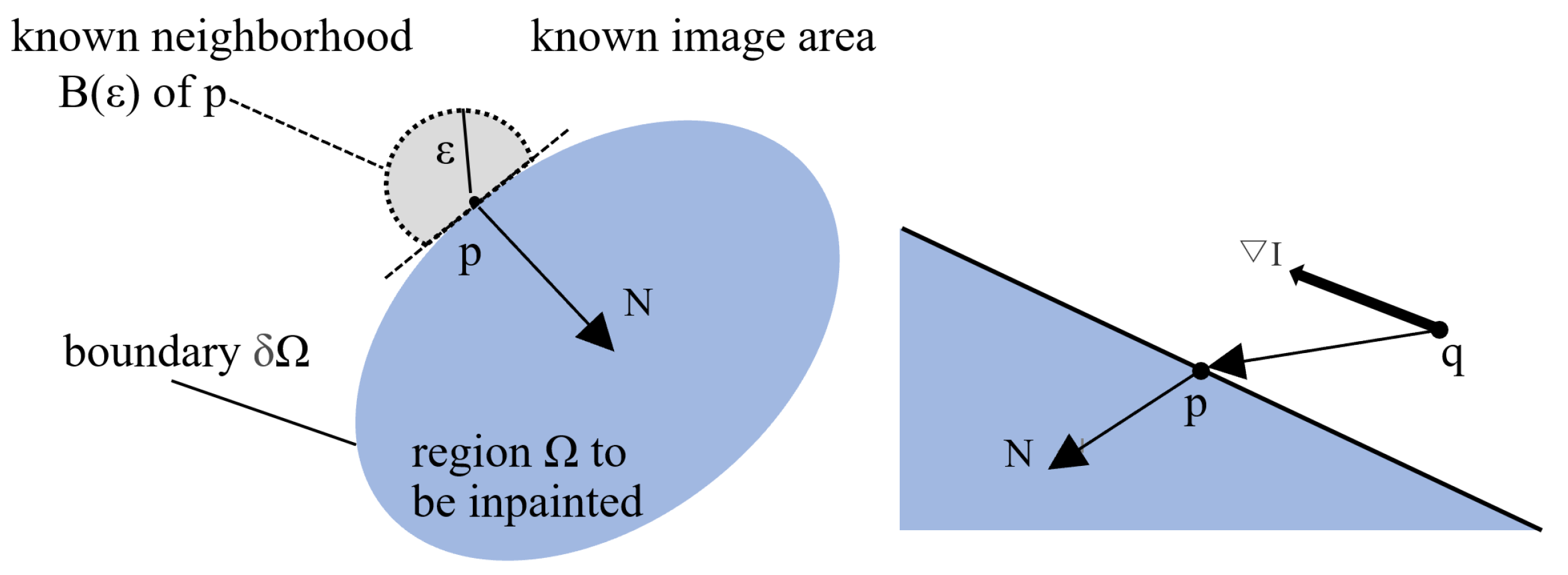
Image inpainting refers to a technology in which the information in the local area of an image is lost. The purpose of image inpainting is to restore this information. In the field of traditional image inpainting, there have been many methods, such as the fast marching method (FMM) proposed by Telea [
1], which has a better inpainting effect for small-scale images with small pixel differences and semantically poor images with missing areas. However, for large areas, large pixel differences and language-rich images with missing areas are very lacking in repairing effects, incoherent chromaticity in repaired areas, blurred content, and missing texture information. Criminisi [
2] proposed the block-based image inpainting method (BBIM). This method considers texture information compared with the FMM. If the information of the object to be repaired is more complex or involves areas where multiple texture structures intersect, there will be repair dislocation and incomplete pixel filling, and it will lead to missing or empty results in the generated pointcloud data.
The FMM and BBIM all first obtain the mask image according to the binarization of the damaged image, then repair the original image based on the mask image. The missing pixel information in the image’s damaged area is not uniform, or the pixel value of the damaged boundary area is not far from the normal value; the set binarization threshold range is too small. This will cause the effective information extracted from the mask image to be incomplete. As a result, the repair is synsemantic and the information of the pointcloud data is lost.
From these conditions, in order to obtain complete pointcloud data for subsequent 3D reconstruction and other related applications, we propose the following optimization scheme.
(1) For large image inpainting, the original image is divided into blocks, and only the image blocks that need to be restored are selected for subsequent operations. This reduces repair time and increases efficiency.
(2) When the pixel value of the damaged area is uniform, the extracted mask image is relatively complete. It also can fully cover the required repair area. However, the image damage is not deliberately damaged, and the lost pixel information is often uneven. The mask image extracted at this time needs to undergo two expansion processes to make it cover the damaged area as much as possible.
(3) The mask image after the expansion process was combined with the original image for inpainting. There are often some subtle holes that are not completely repaired. At this time, even a second repair is already saturated. Based on this, image sharpening is performed on the area to be repaired in order to avoid disturbing the intact area. It alse can enhance the information of the area to be repaired, and then the mask image is extracted by binarization for subsequent inpainting.
In this paper, we consider the characteristics of the image to be repaired with vertical scratches (pixel values decay with the center of the scratches to both sides), which is not reflected in the original method. Secondly, in view of the shortcomings of the basic method, such as long repair time and low repair efficiency, we propose an image block parallel repair method to speed up the image repair speed and improve the repair efficiency.
2. Related Works
Bertalmio [
3] and others first proposed the concept of image inpainting. The traditional image inpainting method mainly performs speculative inpainting based on the connection and continuity between pixels. In recent years, the research of image inpainting technology can be mainly divided into two methods: pixel-based and block-based.
The pixel-based method is suitable for repairing small-sized damaged images. This method mainly includes the partial differential equation (PDE) method, the variational method, and the interpolation method based on known information. The PDE method uses the edge features of the known area to estimate the iso-illuminance line direction and uses the push method to transmit the information along the iso-illuminance line direction to the area to be repaired. The BSCB method [
3] and curvature diffusions repair method [
4] were used. The variation-based method transforms the image inpainting process into a functional maximal value variational problem [
5,
6,
7,
8]. The interpolation method, based on known information, is to import the pixel value of the complete region of the image into the relevant equation. The calculated value is then used to update the point to be filled [
1].
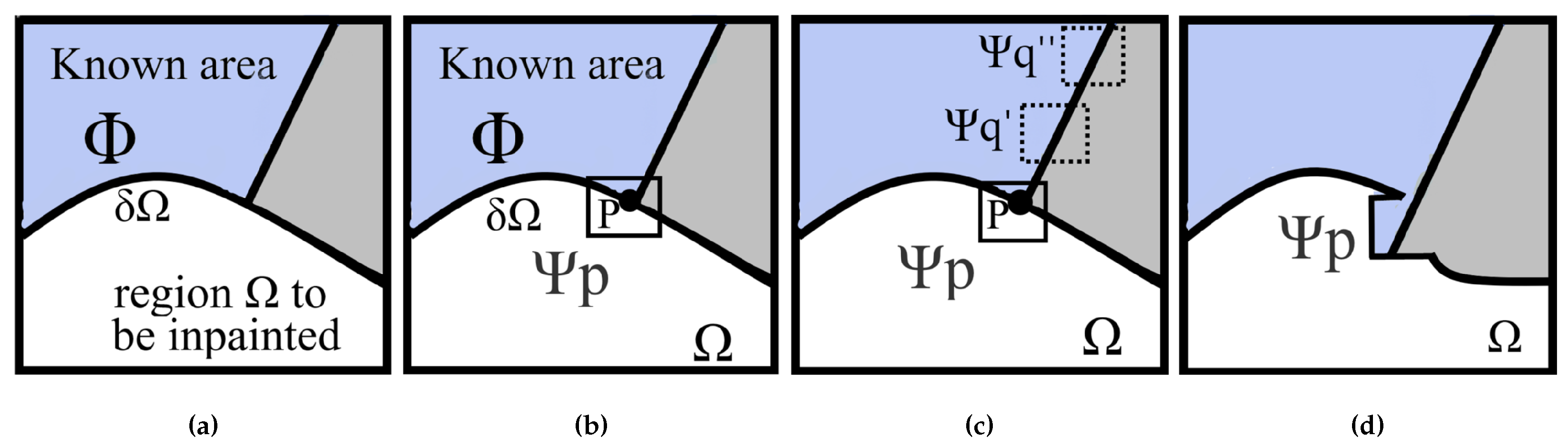
One of the methods based on block images is to obtain the boundary of the damaged area, sorting by the priority value of all points on the boundary. To employ this method, set up a module region with the highest priority value as the center. Match the template area with the original image area to obtain the block with the minimum mean square error. Finally, input the texture and structure information together to update the confidence value [
2]. Based on this method, Luo [
9] improved it and proposed a repair algorithm for depth image. Xu [
10] proposed two sparse concepts, which distinguish between structural repair and texture repair. It uses the non-zero similarity sparsity of the repaired region and its adjacent region to obtain the reliability, and it improved the repair sequence. Anamandra [
11] also introduced the gradient and its corresponding log value based on the selection of priority, achieving good repair effects. Huang [
12] introduced the affine transformation matrix to realize geometric transformation of sample blocks, effectively improving the image repair effect.
Pointcloud data is widely used in the 3D reconstruction of objects due to its good shape expression ability. It also can reflect the 3D information of objects [
13]. In the methods for generating pointclouds by using the RGB-D dataset [
14,
15], we see that if the image is damaged or the pixels are lost, the pointcloud data will cause holes or missing areas. In order to accurately restore the morphological characteristics of the scene, filling the pointcloud holes is also one of the basic tasks of the subsequent 3D reconstruction. The existing research methods for pointcloud hole filling mainly include three methods: based on known information, based on matching, and based on learning.
The method based on known information uses the geometric features of existing pointcloud data to complete the whole pointcloud filling. For example, Tu [
16] proposed a method based on Kriging interpolation, using the known points around it as a reference to fill the missing pointcloud. However, if the missing area of the pointcloud is too large, the geometric characteristics of the missing area cannot be estimated. Thus the missing area cannot be supplemented.
The core idea of the matching-based method is to use the model in the known pointcloud database to match the missing area of the pointcloud to achieve the completion task. By using both the deformation method [
17] and the seamless stitching of triangular meshes based on Poisson equation [
18], we complete the hole filling by triangularizing the cluttered pointcloud data to synthesize the geometric shape to be more consistent with the input. Li [
19] proposed a method for repairing a pointcloud based on triangular meshing, which is to establish a tetrahedron by combining 3D curves and damaged pointclouds and then optimizing the tetrahedron for 3D curves. Finally, the mesh surface is extracted from the tetrahedron for pointcloud filling.
The learning-based approach is the recent widespread use of deep learning to process pointclouds directly [
20,
21]. Using neural networks to learn the characteristics of pointcloud data, and then directly filling the missing pointcloud has become a popular field of pointcloud repair research. For example, Qi proposed to use the PointNet network structure [
22] to directly apply the deep learning network structure layer to the pointcloud data. The process of using deep learning for pointcloud repair is roughly to output the complete pointcloud directly after processing the pointcloud data to be repaired. On the basis of the literature [
22], a PointNet++ network structure [
23] is proposed, which is used for the processing of pointcloud data restoration. In the method of using RGB-D images to synthesize pointcloud, if the RGB image or depth image is damaged, it will also cause pointcloud holes. For the missing area of depth image, Zhang [
24] only needs to input an RGB image and a depth image, which can fill the missing information of any depth map and achieve good results. It’s also beneficial to the 3D reconstruction of pointcloud data based on the RGB-D dataset. Another method is the deep Laplacian pyramid network based on deep image enhancement using CNN, which has achieved good results by reducing the noise and holes of deep image in a cascading way [
25]. This paper is based on the method of the pointcloud formed by the RGB-D dataset [
14,
15], through the repair of image pixel-loss area, the hole filling of the final pointcloud. Through the final repair effect, the practicability of the method is verified.
4. Related Methods Analysis
4.1. Image Preprocessing Methods
Image Dilation
Image binarization occurs when the pixel values of the damaged area and other areas are 255 or 0. The purpose of image dilation is to enlarge and thicken the area to be repaired. In this way, the repair failure caused by an uneven boundary pixel value can be alleviated.
Define the Expansion operator as ⊕.
B is used to expand image A, where B is A convolution template or convolution kernel. The convolution calculation is carried out between template B and image A, and every pixel in the image is scanned. The “” operation is performed with the template element and binary image element. If both are 0, the target pixel is 0; otherwise, it is 1. Thus, the maximum value of pixels in the covered area of B is calculated. And the pixel value of the reference point is replaced by this value. Therefore, the expansion result is the expansion and thickening of the white highlighted area. In order to cover the boundary of the region to be repaired in the binary image, we select the full 1 matrix with the dilation convolution kernel of 5 × 5.
Dilation Convolution Kernel Image Sharpening
In the differential operation of image sharpening, the Laplace operator is commonly used [
26]. As a linear quadratic differential operator, the Laplace operator has anisotropy and displacement invariance, which satisfies the sharpening requirements of image boundaries with different orientations.
For the digital image, the second-order partial derivative can be expressed by the second-order difference approximation, so the Laplace operator is defined as
where
represents the pixel value of a image.
According to Equation (
9), the Laplacian operator is based on the change of one pixel relative to four adjacent pixels,
where
represents the pixel value sharpened by the Laplacian operator.
The mask image cannot completely cover the damaged part, and the binarization operation has a limited range of distinguishing pixel values. With the help of image sharpening, the purpose is to make the blurred image clear. It also can enhance the edges and contours of the image details, and it enhance the grayscale contrast so the image that has been repaired once can be extracted through the binarization operation, again for image inpainting. Because the pixel value of the image after sharpening has been changed, we only use the mask image extracted after sharpening to combine with the original image to be repaired before repairing.
Image Sharpening Convolution Kernel Image Block
For the processing of large images, due to the limitation of the repair method, the efficiency has reached the limit after the first repair. However, there is still a small part of the area that has not been completely repaired. We use multi-thread method to process the original image by region. Only the small image regions to be repaired were extracted and repaired again. Eventually, the regions are regrouped. This avoids recovery limitations due to repair efficiency and speeds up repair.
4.2. Implementation Details
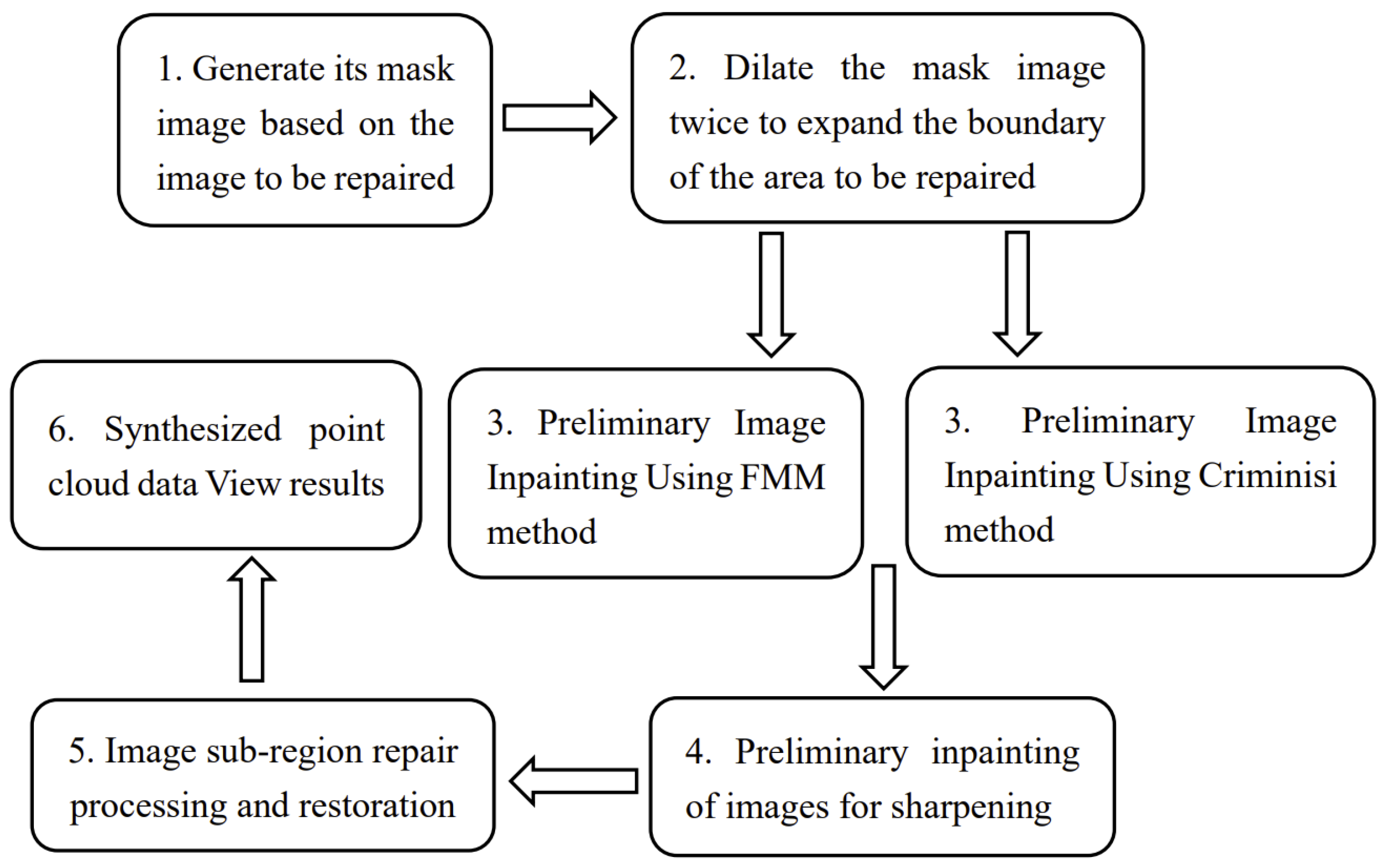
First, the image to be repaired is binarized to extract the mask image. The mask image segmented the area to be repaired. The image dilation algorithm is used to expand the area to be repaired in the mask image twice. The original image is repaired by FMM or BBIM. Sharpen the image obtained in one repair and then divide it into blocks. Then fill in the small area to be repaired and restore it in blocks to obtain the final image restoration result. In the end, convert the final restoration result into pointcloud data to view the restoration result of pointcloud data.
4.3. Image Dilation Results
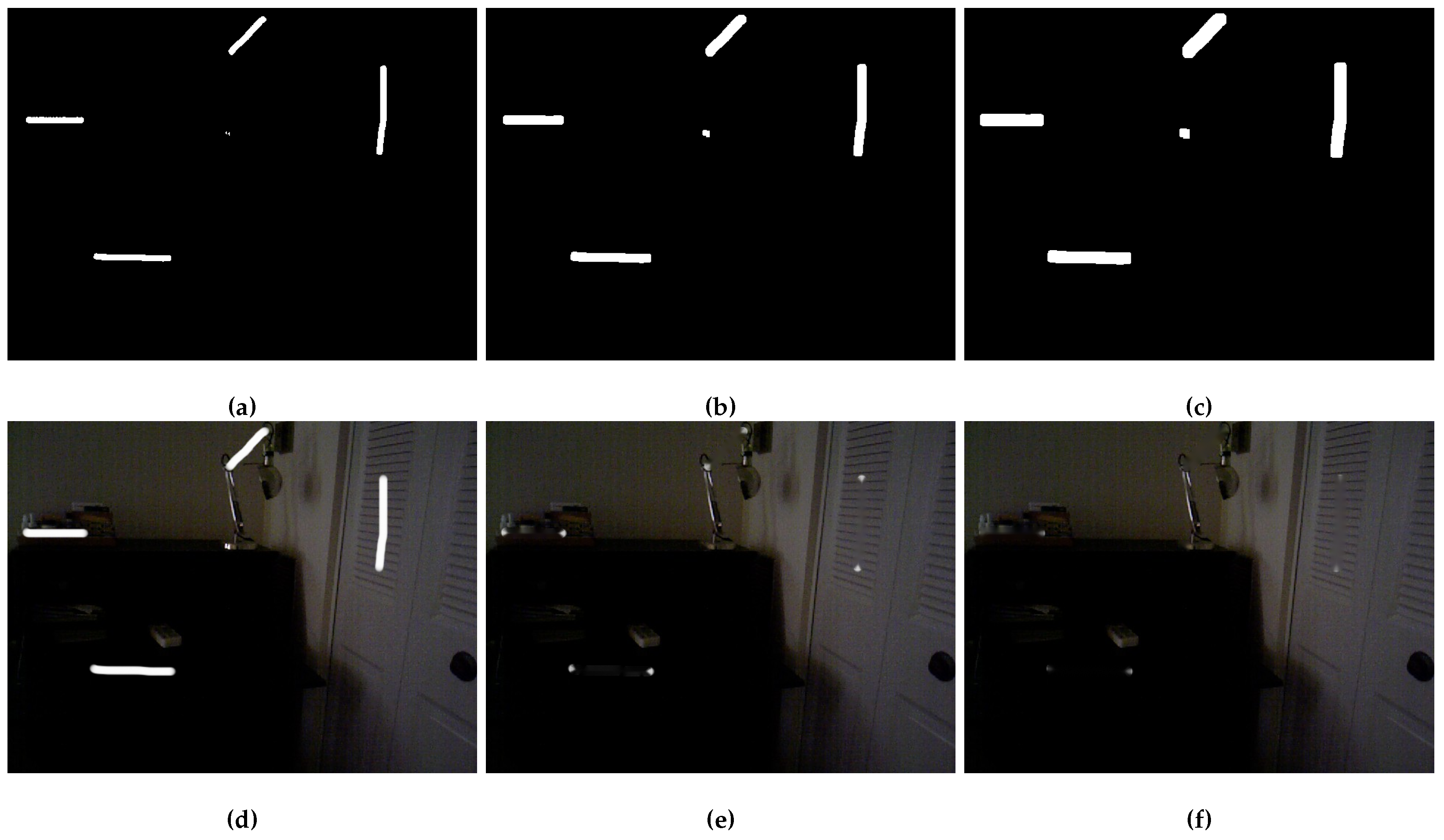
After using the FMM or BBIM method to repair the image, there are still small areas not completely repaired on the boundary, as shown in
Figure 4e. But the repaired results have reached the limit of FMM and BBIM methods. Effective inpainting areas cannot be extracted from mask again. According to the size of the expansion convolution kernel we set up and the experimental results. The mask, after expanding twice, can better express the region to be repaired. The method processing flow proposed in this paper is shown in
Figure 5.
It can improve the efficiency of repairing. From the result in
Table 1, it can be concluded that the PSNR of the repair results after our processing is improved by 1.92 dB.
4.4. Image Sharpen Results
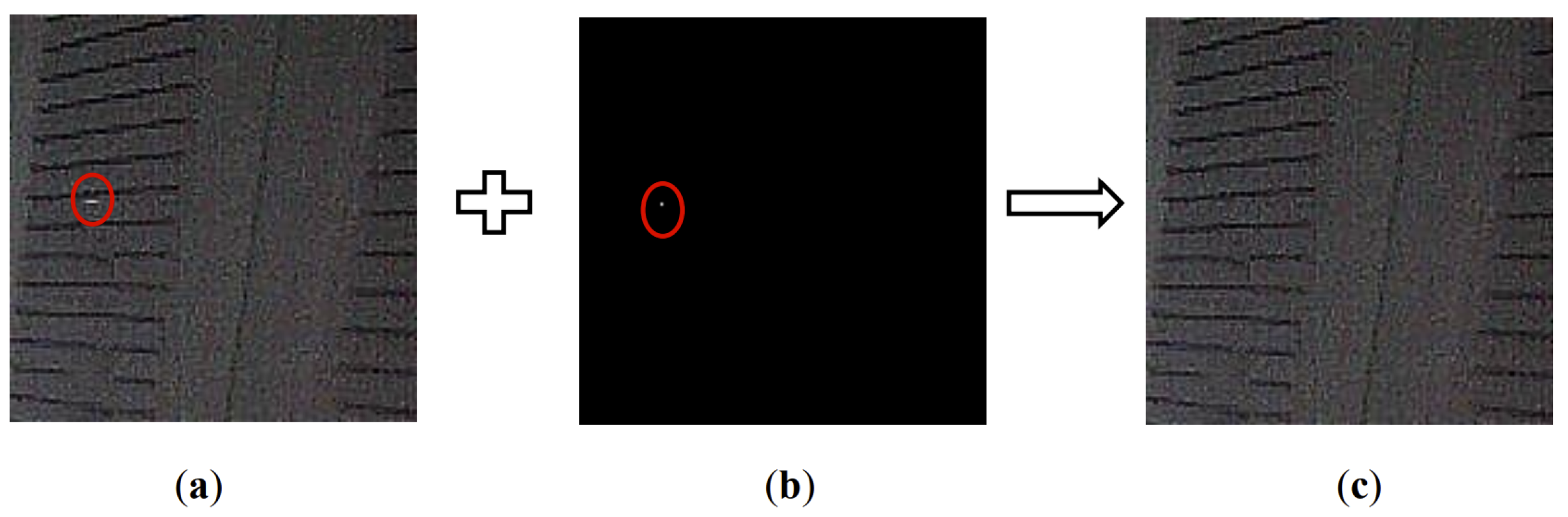
Figure 6a is the result of the our method combined with the BBIM proposed by Criminisi.
It can be seen that most of the damaged parts of the image have been repaired and the texture information of the repaired area has been restored more efficiently. However, the characteristic of the edge of the image is that the grayscale change on the edge is relatively gentle, whereas the grayscale change is faster on both sides of the edge. Consequently the gradient value is large. It is usually the part with local discontinuity and the most significant change in brightness. It leads to the fact that there are still subtle parts of the damaged boundary that have not been completely repaired. At this time, the edge information of the area to be repaired is enhanced after the image-sharpening process. Its detailed features are highlighted, so that the mask image can be extracted after further binarization in
Figure 6b.
4.5. Image Block Results
Although the unrepaired edge information of the abovementioned sharpened image has been enhanced, the unrepaired area has reached the repair limit of the above two methods. If the mask image is extracted by binary operation again, no area to be repaired has been extracted, but there are still subtle areas not repaired completely.
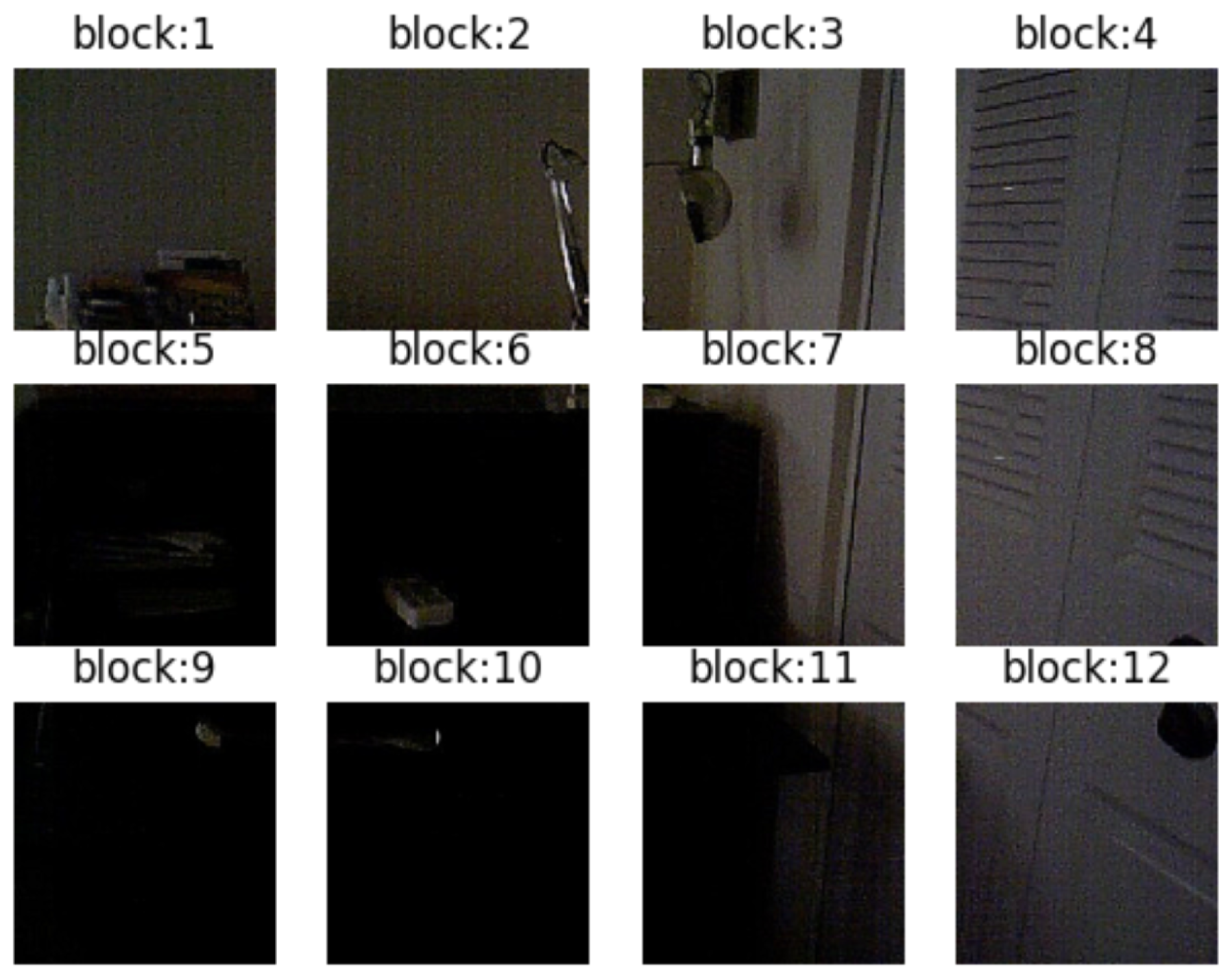
In order to solve the above problems and speed up the repair, we propose a method to fill small areas to be repaired by using multi-threaded images. We divide the original image into small areas for processing, as shown in
Figure 7. Next, the block image containing the damaged region is sharpened to enhance the boundary information. Then, it is repaired again, and the repaired result is shown in
Figure 8c.
We divide the image into blocks such as Equation (
12),
where
m and
n represent the image width and height,
represents the greatest common divisor,
b represents that the image is partitioned into rows
b, and
a represents that the image is partitioned into column
a.
In the experiment, the size of the images we used was 640 × 480. According to Equation (
12), m = 640, n = 480, so the GCD = 160, and a = 640/160 = 4, b = 480/160 = 3, the input image is divided into 3 × 4.
4.6. Pointcloud Visualization by RGB-D Odometry Method
RGB-D odometry method is one of the methods used to generate pointcloud data, and it is used to find the camera movement between two RGB-D images. Its input is a pair of RGB-D images, and its output is the motion in the form of rigid body transformation. The specific method is to convert the RGB image of 3 channels into the gray image of 1 channel, and then combine the depth image of a 1 channel with the camera to convert it into pointcloud [
14,
15].
First, an RGB-D Image is created by using a pair of color and depth images, and a proportional depth value is set. The depth value is scaled and then truncated. The color image is converted to a gray image and stored in the range of [0,1]. The depth image is stored in another floating point number and represents the depth value in meters.
Given the depth value
d at pixel
, the corresponding 3D point is
,
where focal length (
,
) = (525.0, 525.0), optical center (
,
) = (319.5, 239.5), and
is 1000. Pixels
need to be converted from pixel coordinates to camera coordinates to display each point
in the pointcloud. According to the principle of similar triangles,
,
, and
Z is represented by the depth
d of the corresponding point and the scaling coefficient
.
Matrix Parameters of Camera 5. Final Results
5.1. Image Inpainting
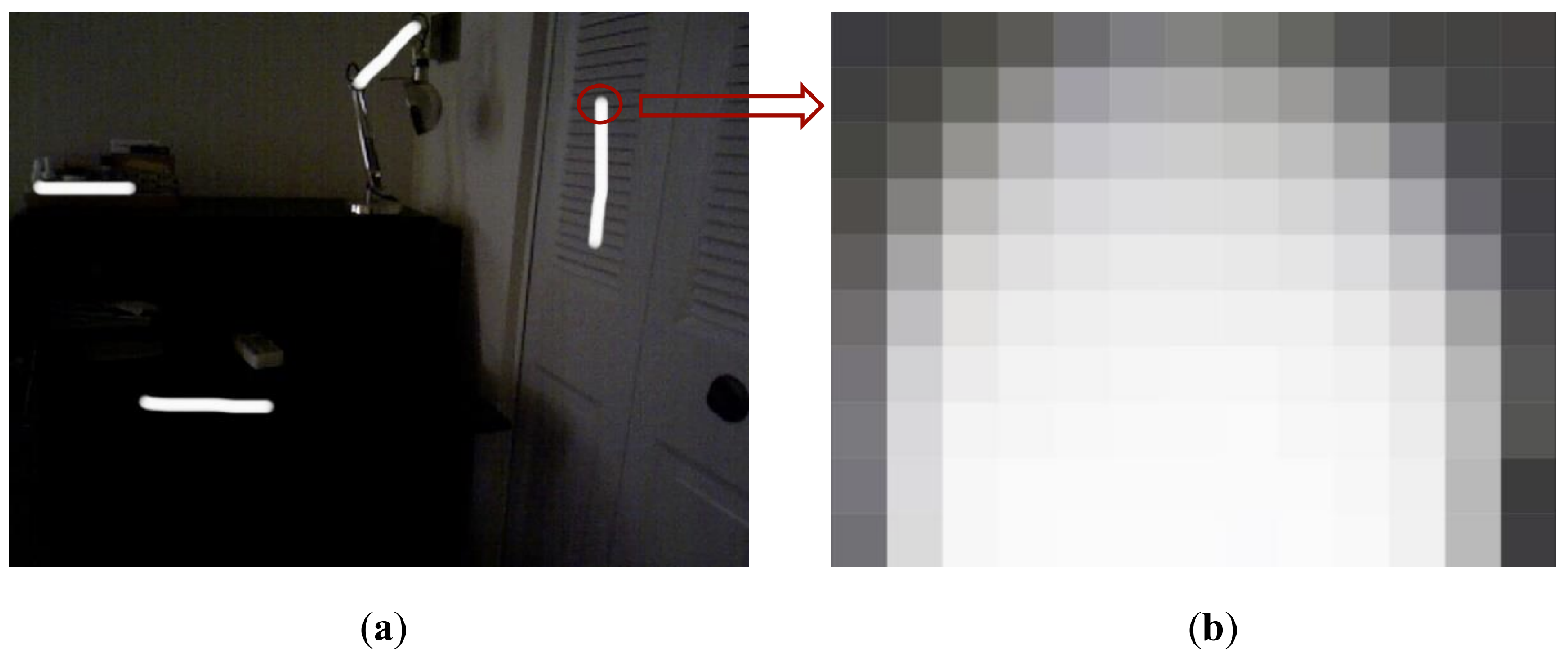
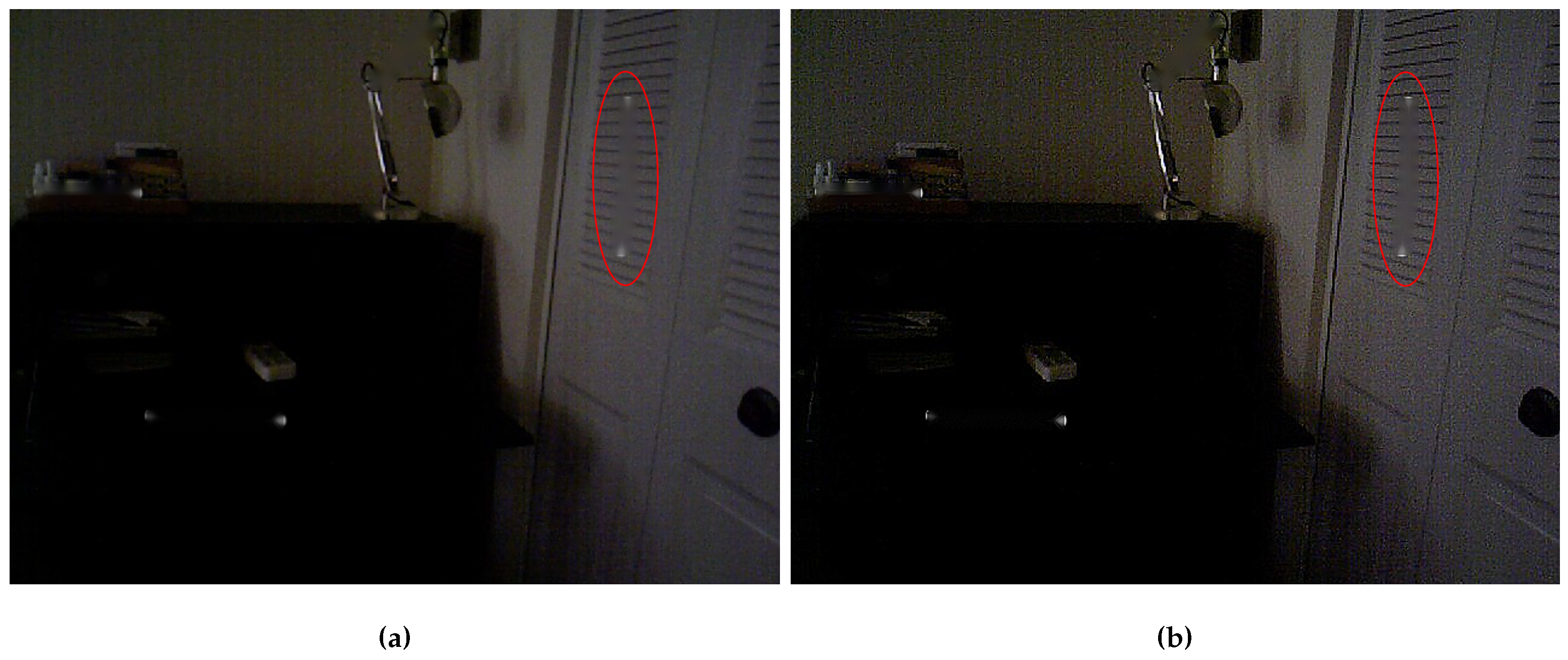
The common damage of images, such as vertical scratches, scratches of any shape, and dust, seriously affect the quality of images. The vertical scratch is a kind of continuous damage, strip shape. The pixel value of the damaged area is attenuated chord distribution, that is the pixel value of the damaged area decreases with the increase of the distance from the center area [
27], as shown in
Figure 9. Here, we artificially created images with vertical scratches, as shown in
Figure 10a.
Figure 9b is the magnification effect diagram of the damaged area boundary in
Figure 9a.
This experiment is implemented in a laptop environment with an Intel(R) Core (TM) i5-9300H CPU@2.40GHz, 8.0 GB memory and 64-bit Windows 10, using Python 3.6 as the algorithm platform.
In order to verify the effectiveness of our proposed method, the images used in this paper are mainly NYU-Depth V2 dataset and Redwood dataset images. The NYU-Depth V2 dataset contains 1449 annotated RGB images and depth images with the size of 640 × 480. The image structure of Redwood dataset is the same as the NYU-Depth V2. We selected representative indoor scenes from these two datasets, such as living rooms, bedrooms, etc. The peak signal-to-noise ratio (PSNR) is used as the objective evaluation index of the restoration effect.
The experimental content is to use the improved method based on FMM and BBIM to repair the image, and compare with the original method to repair the image, and use PSNR to reflect the difference between the repair effect before and after the improvement.
The calculation method of PSNR is as follows:
where
m and
n represent the image width and height, respectively,
represents the maximum gray value of all pixels in the image,
S represents the original image, and
J represents the restored image.
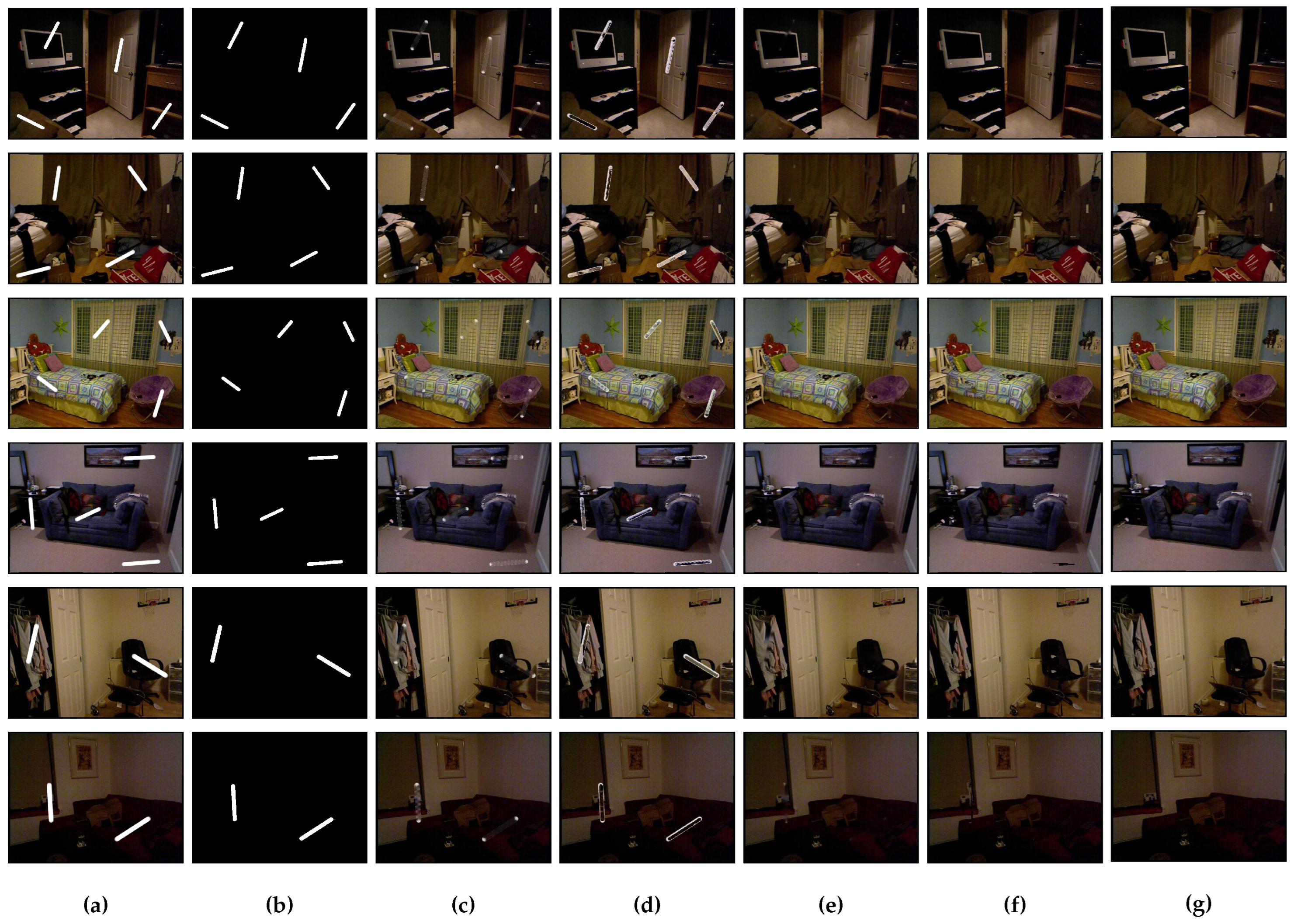
Both the FMM method and BBIM method rely on known information of damaged region boundaries for image inpainting. But for the image to be repaired with vertical scratches, the pixel values of the boundary of the damaged area are attenuated chord distribution. When binaryzation is used to extract the mask image, the boundary is not completely extracted. In this way, the edge damaged areas that we did not extract during image inpainting are also treated as known area information. These pixel values, as known information of the damaged boundary, become a reference instead of the damaged region pixel values. So the final FMM method and BBIM method repair effect is not ideal, as shown in
Figure 10c,d.
In view of the situation that the pixels of the image are lost due to the vertical scratches (as in the mask, the FMM method, and BBIM method), we use morphological analysis optimizations and update the masks by dilation and sharpening. After processing, the effect of image restoration is more ideal, such as in
Figure 10e,f. We also use PSNR to represent the results of image inpainting, as shown in
Table 2.
Because we use the pointcloud generated by RGB-D Odometry Method, the RGB image and depth image become two important factors affecting the pointcloud. In
Table 2, PSNR is used as the evaluation standard of the RGB image inpainting results. In order to comprehensively consider the two factors, we add the same scratches as RGB images to the depth image of the input image in
Figure 10a and repair them. The results of PSNR are used to evaluate the results of depth image repair, such as in
Table 3. The results of
Table 3 show that for the inpainting of depth images, the FMM method and BBIM method after the proposed method are more effective than the original basic method.
5.2. Multithread Image Inpainting Result
The BBIM method is based on the principle of image block matching repair, and its basic idea is similar to that of FMM method. It introduces the concept of priority as a condition for filling pixel sequence selection. When repairing an image by the BBIM method, the first image block is selected from the area to be repaired and replaced by matching until the last image block of the area to be repaired is calculated. In order to shorten the repair time, we divide the image into blocks for multithreading repair.
According to the size of the input image, the number of input image blocks is calculated according to the principle of image block. The binary mask image processed by dilation method is also divided into the same blocks as the input image. In the basic BBIM method and FMM method, especially for block matching based on the BBIM method, it takes a lot of time to calculate the priority of filled blocks. In the process of image inpainting by using the BBIM method, a block with the highest priority is found according to the global image to fill the repair area. If the input image size is too large, it will also increase the calculation time for calculating the priority selection of filling blocks. In the local continuous region of the image, most of the pixels closer to the position have similar pixel information. Therefore, we divide the image to be repaired into several image blocks with the same size as the mask image, and repair these image blocks at the same time. Because the size of the image block becomes smaller and multiple repair areas are processed at the same time, the efficiency of image is effectively improved. We calculate the repair time of RGB images and depth images in
Figure 10a, and the results are shown in
Table 4 and
Table 5.
The method of multi-thread repair in sub-regions is used, which improves the timeliness of the method and speeds up the repair speed.
5.3. Generate Pointcloud Data Result
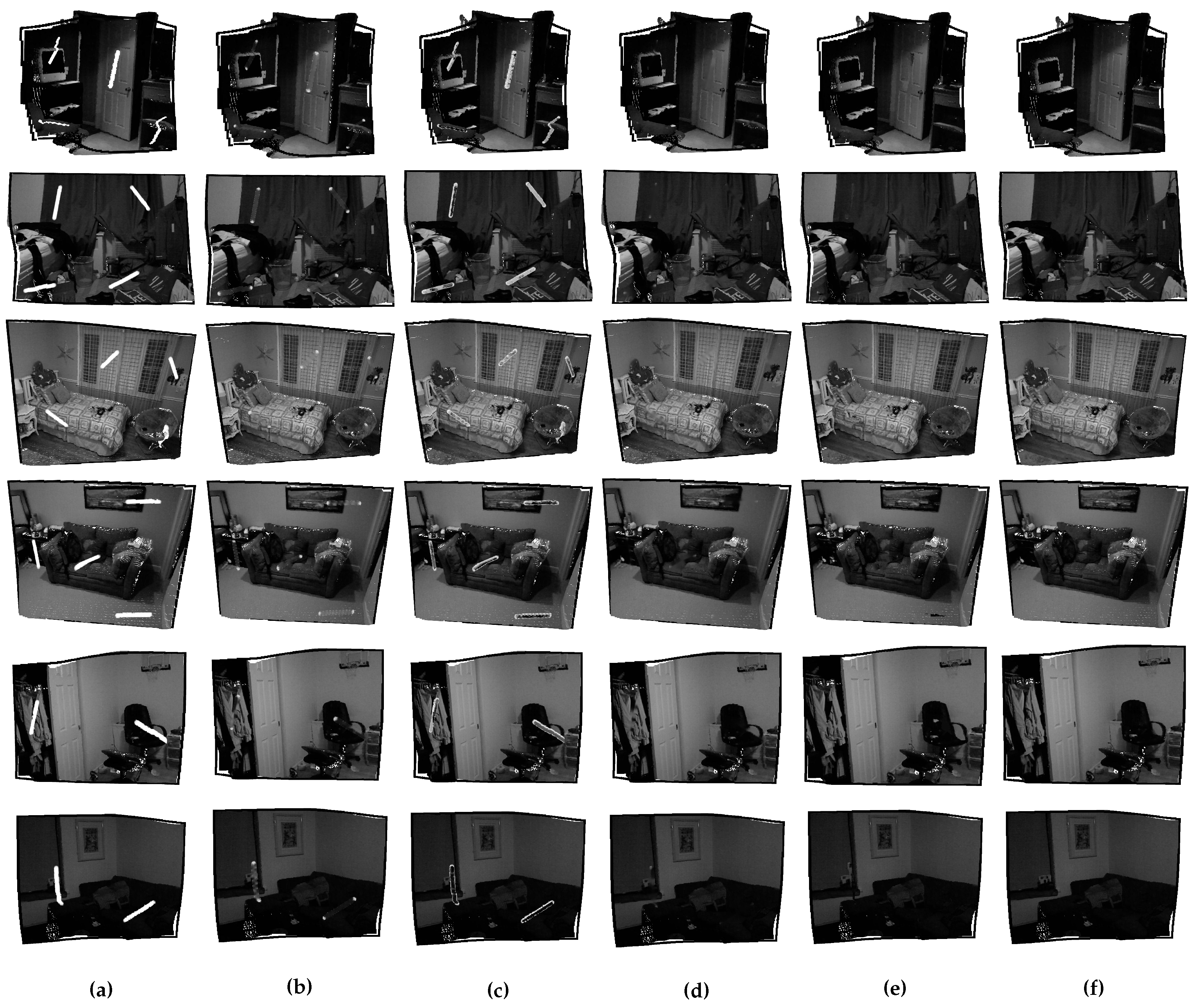
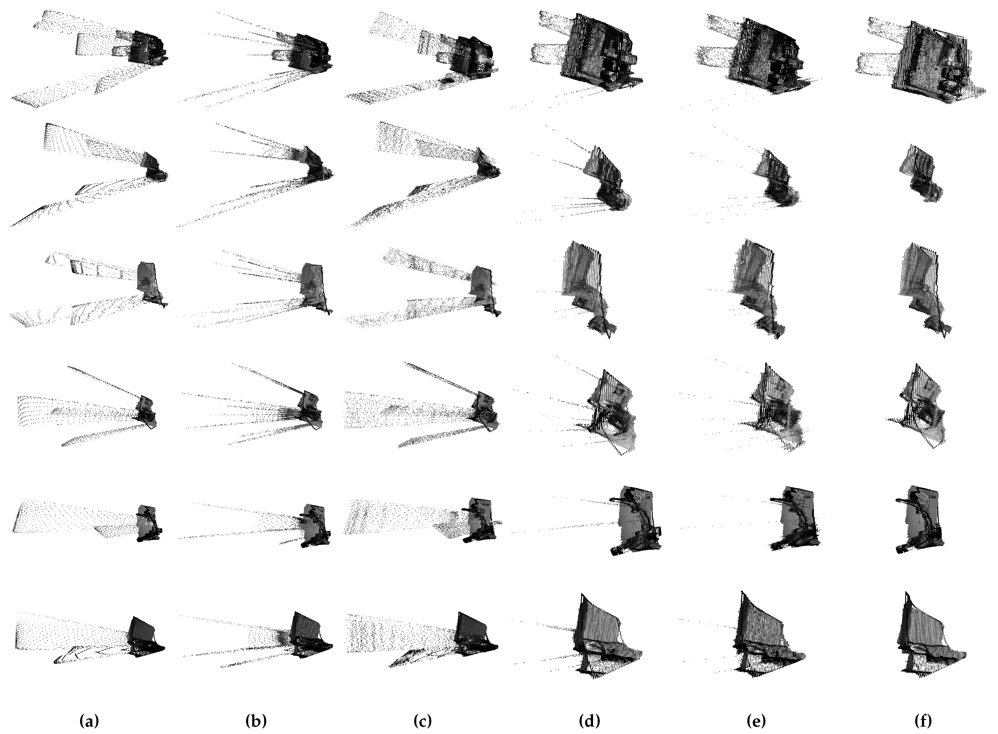
Our pointcloud generation method is based on the RGB-D odometry method. Pointclouds generated by using broken RGB images and depth images are shown in
Figure 11a. The damaged area of the RGB image causes holes in pointcloud data. The pointcloud data repaired by using the FMM method and BIMM method are shown in
Figure 11b,c. Because the boundaries of unextracted damaged areas are introduced in the repair process, and the boundaries of these damaged areas are used as reference information for repair, the repair effect is unsatisfactory. The broken RGB image we used in the process of generating pointcloud results in a hole in pointcloud data.
Because the RGB image has scratches, the pointcloud generated by RGB-D will produce a pointcloud missing as shown in
Figure 11a. Each pixel value in the depth image represents the plane distance between the scene object and the camera. If the depth image has scratches, the pointcloud depth error shown in
Figure 12a will occur.
Figure 12b,c is the pointcloud synthesized by using the basic FMM and BBIM methods to repair the depth image. As the result of RGB image inpainting, the boundary of the area to be repaired in the depth image is not completely repaired, so the depth information of the boundary of the area will be wrong, which will affect the generated pointcloud.
Figure 11d,e and
Figure 12d,e show the pointcloud data processed by the proposed method combined with FMM method and BBIM method, and the repair effect is improved. However, it can be seen from the side view that even if the repair effect is improved compared with
Figure 12b,c, there are still subtle incomplete parts in the scratch boundary area, which leads to some errors in the depth information of the boundary.
6. Conclusions
We propose a new method for processing image inpainting, which is based on the FMM proposed by Telea and BBIM proposed by Criminisi, and which combines some image-processing methods, such as the dilation method for mask image, operations on sharpening, and image block processing of image.
We have proved that the above two repair methods combined with the our method can achieve better repair results. It can also better reflect the texture information of the damaged area, and the repair speed is faster. The repaired pointcloud data fills in the information of the defective area, so that it can better reflect the three-dimensional space state of the object. It is more conducive to the extraction and segmentation of the target object when using the pointcloud data for 3D reconstruction and other applications.


