Review

On Physical Aeroacoustics with Some Implications for Low-Noise Aircraft Design and Airport Operations

by
Luís M. B. C. Campos
CCTAE (Center for Aeronautical and Space Science and Technology), Instituto de Engenharia Mecânica (IDMEC), IST (Instituto Superior Técnico), Universidade de Lisboa, Av. Rovisco Pais, 1049-001 Lisboa, Portugal
Aerospace 2015, 2(1), 17-90; https://doi.org/10.3390/aerospace2010017
Submission received: 23 October 2014 / Revised: 11 November 2014 / Accepted: 20 January 2015 / Published: 4 February 2015
(This article belongs to the Special Issue Driving Forward Aerospace Innovation)

Abstract

:
Air traffic is growing at a steady rate of 3% to 5% per year in most regions of the world, implying a doubling every 15–25 years. This requires major advances in aircraft noise reduction at airports, just not to increase the noise exposure due to the larger number of aircraft movements. In fact it can be expected, as a consequence of increased opposition to noise by near airport residents, that the overall noise exposure will have to be reduced, by bans, curfews, fines, and other means and limitations, unless significantly quieter aircraft operations are achieved. The ultimate solution is aircraft operations inaudible outside the airport perimeter, or noise levels below road traffic and other existing local noise sources. These substantial noise reductions cannot come at the expense of a degradation of cruise efficiency, that would affect not just economics and travel time, but would increase fuel consumption and emission of pollutants on a global scale. The paper reviews the: (i) current knowledge of the aircraft noise sources; (ii) the sound propagation in the atmosphere and ground effects that determine the noise annoyance of near-airport residents; (iii) the noise mitigation measures that can be applied to current and future aircraft; (iv) the prospects of evolutionary and novel aircraft designs towards quieter aircraft in the near term and eventually to operations inaudible outside the airport perimeter. The 20 figures and 1 diagram with their legends provide a visual summary of the review.

Graphical Abstract

1. Introduction

The present paper attempts to make a concise but comprehensive review of the problem of aircraft noise near airports, organizing the contents in four chapters. Chapter 2 concerns the physics of sound generation and propagation, that is the noise sources associated with propulsion and aerodynamics that are responsible for aircraft noise. The Chapter 3 addresses the modification of the spectrum and directivity of aircraft noise due to atmospheric and ground effects, that is the difference between emitted aircraft noise and the noise received by the near-airport resident, and its effects as an annoyance to living, working and sleeping habits of near-airport resident. The Chapter 4 lists a number of noise reduction measures that can be applied to aircraft, taking into account the associated penalties in weight, fuel consumption and complexity and how much can be expected in return as an achievable noise reduction. The Chapter 5 considers evolutionary and novel aircraft configurations needed to achieve substantial noise reductions towards the objective of an aircraft inaudible outside the airport perimeter. The conclusion summarizes the gap between this ultimate aim and the current state-of-the-art.
The focus of the paper is aeroacoustics as branch of physical sciences (Section 2 and Section 3) addressed by: (i) considering well established theories that underlie current knowledge and common practice; (ii) in addition highlighting scientific developments that are perhaps less well known and whose dissemination and application could lead to further progress. The references include: (i) recent work that indicates the state-of-art and currently prevailing methods; (ii) their scientific background and related problems sometimes dating back to the early days of physical sciences. The combination (a) of well and less known theories and also (b) of recent work and its earlier background, is intended to give a broad view of the scientific basis of aeroacoustics, that is related to the current issues of low-noice airport operations (Section 3) and aircraft design (Section 4). The latter two issues involve other aspects beyond aeroacoustics, that are mentioned more briefly in passing, since the main aim is to link aeroacoustics as a physical science with the engineering and operational aspects of low-noise aircraft design.

2. Noise Generation and Propagation

The noise generation mechanisms in an aircraft are related to propulsion, aerodynamics and their interactions. Jet engine noise has been reduced dramatically since the dawn of the jet age due the increased by-pass ratio of turbofan engines, leading to a win-win situation because the lower average jet velocity has twin benefits: (i) increasing propulsion efficiency and reducing specific fuel consumption; (ii) reducing noise by shielding the hot high-speed core jet by a surrounding colder and slower fan flow. The success in reducing jet engine noise has lead to the current situation where on approach to land with the engine at idle aerodynamic noise can be dominant. At take-off and other flight conditions engine noise is most important, and the prospects for further reductions by increasing the by-pass ratio of turbofan engines are reaching their limits somewhere between 10:1 and 20:1. Larger by-pass ratios are achieved by unshrouded propulsors, which do without the weight of an engine nacelle, but also lose the benefits of: (i) noise shielding by inlet and exhaust ducts; (ii) sound absorption by acoustic liners on duct walls. The modern counter-rotating ultra-high by-pass-ratio unducted engine adds to the propeller noise that of the interaction of two rotors, one in the wake of the other. This variety of noise generation mechanisms is considered starting with open rotor noise (Section 2.1), proceeding to the noise of ducted engines (Section 2.2) and concluding with installation and flight effects (Section 2.3) in addition to aerodynamic noise.

2.1. Open Rotor Noise

The open rotor noise is chosen as the starting point for convenience of presentation, since in this case the noise sources are in free space (Section 2.1) unaffected by the duct acoustics of turbojet or turbofan engines (Section 2.2). In both cases installation and flight effects have to be considered (Section 2.3). From the point-of-view of propulsive efficiency the propeller is the best choice, as long as blade tip speeds do not approach sonic conditions leading to shock waves and a sharp increase in drag. The sonic effects are of no concern for slower regional aircraft and can be minimized for modern high-speed rotors with advanced blades using supercritical airfoil sections. The airplane propellers provide thrust in horizontal flight, as helicopter rotors provide lift in vertical flight, and there is a combination of thrust and lift for a helicopter in forward flight. There is one important difference regarding noise: the aircraft propeller (Section 2.1.1) leaves a vortical or turbulent wake behind, whereas for as helicopter rotor (Section 2.1.2) the wake of one blade can impinge on the next or following blades, creating a characteristic flapping noise. This blade-vortex interaction (BVI) noise applies not only to helicopter rotors (Section 2.1.2) but also to contra-rotating propellers (Section 2.1.3) since the wake of the upstream blades impinges on the downstream blades.

2.1.1. Airplane Propeller Noise

The sources of propeller noise are well modeled by the first theory of aerodynamic sound due to Lighthill Proudman [1,2,3,4,5,6] and extended to solid boundaries [7] and surfaces in arbitrary motion [8,9]. The acoustic or classical wave equation, that applies to linear, non-dissipative sound waves in a homogeneous medium at rest [10,11,12,13,14,15,16] is:
2 ρ t 2 c 0 2 2 ρ x i x i = Q t + F i x i + 2 T i j x i x j ,
where c0 is the sound speed and ρ' is the mass density perturbation of the sound wave, shows that there are three sources of sound. The volume changes Q act as a monopole [17] corresponding to the “thickness” noise of a propeller, due to the fact that it displaces a volume of fluid. The forces Fi act as a dipole, corresponding to the “loading noise” of a propeller, due to the pressure p distribution on the blades Fi = −pNi where Ni is the unit normal. The stresses act as a quadrupole, namely the Lighthill tensor:
T i j = ρ v i v j + ( p c 0 2 ρ ) δ i j + σ i j ,
consisting of: (i) the Reynolds stresses modeling noise generation by turbulence; (ii) the non-homentropic terms of the equation of state p = p(ρ,s) where s is the entropy, leading to “entropy noise” (Section 2.2.3); (iii) the viscous stresses σij act as weak heat sources and also as a wave dissipation mechanism.

2.1.2. Helicopter Rotor Noise

The first theory of aerodynamic noise applies equally [18,19,20,21,22,23] well to the to thickness (monopole), loading (dipole) and turbulence (quadrupole) noise of aircraft propellers [24,25,26,27,28,29,30,31,32,33,34,35,36,37,38,39,40] (Section 2.1.1), helicopter rotors [41,42,43,44,45,46,47,48,49,50,51,52,53,54,55] (Section 2.1.2) and turbomachinery [56,57,58,59,60,61] requiring that the aerodynamic problem be solved first to specify the sources. The blade–vortex interaction noise (BVI) involves sound radiation by noise sources convected in a non-uniform flow, that does not match so well the assumptions of the first theory of aerodynamic sound of an unbounded medium at rest or in uniform motion with static or moving sources. In the case of BVI the vortices, as the fluid blobs of entropy noise (Section 2.2.3) are convected by a non-uniform flow past obstacles (rotor blades) that act as a reflector modifying the sound field (Figure 1). In this case further insight can be gained from the second theory of aerodynamic sound [9,62,63,64,65,66,67,68] concerning sound generation in a non-uniform potential mean flow for which the classical wave Equation (1) is replaced by [6,9,66,67,68]:
( t + v 0 . x ) [ 1 c 0 2 ( p t + v 0 . p x ) ] 1 ρ 0 ρ 0 d x . p x 2 p x i x i = J + G ,
where ρ 0 , c 0 , v 0 are the mass density, sound speed and velocity of the mean flow that may be non-uniform (and unsteady) and p is the acoustic pressure perturbation. For a homogeneous medium at rest the . h . s . of (3) reduces to the classical wave equation on the . h . s . of (1). For a homogeneous medium in uniform motion ( ρ 0 , c 0 , v 0 ) are all constant, and the . h . s . of (3) is the convected wave operator. For a non-uniform and/or unsteady mean potential flow the high-speed wave operator [66,67,68] on the . h . s . of (3) has several other terms [9,68] and can be extended to non-linear sound [69,70,71]. The sound sources on the r.h.s. of (3) are relevant both to the blade-vortex interaction (BVI) of helicopters (Section 2.1.2) and to the noise of contra-rotating unducted propellers (Section 2.1.3).

2.1.3. Noise of Contra-Rotating Propulsors

The noise sources on the r.h.s. of (3) corresponding to the second theory of aerodynamic sound consist of: (i) a monopole term J associated with compressibility in a high-speed flow [9,68]; (ii) the force dipole G is the dominant noise source for low Mach number mean flow, and consists of two terms, namely the vortical force (considered next) and the inhomogeneity force (Section 2.2.3). The vortical force [72] corresponds to the Lamb [73] vector, and is equivalent [62] to the quadrupole of Reynolds stresses. The vortical force [72,73,74,75] is exerted by a flow on the component of vorticity (Equation (4a)) crossing streamlines (Equation (4b)):
ϖ v ,                               G v = ρ ϖ v .
The simplest example is an airfoil with Equation (5a) circulation Γ in a uniform stream Equation (5b) with velocity U , when the vortical force Equation (4b) reduces to the lift Equation (5c) in agreement with the Kutta–Joukowski theorem [76,77,78,79,80,81,82,83,84,85,86,87,88,89]:
ϖ = Γ e y , U = U e x ,               G v = ρ Γ U e y e x = ρ U Γ e z .
Figure 1. Vortex and entropy noise pulses. The second theory of aerodynamic sound explains sound emission by: (i) vorticity that is “vortex” sound; (ii) fluid inhomogeneities or patches of unburned gas, that is “entropy noise”. The vortex is subject to a vortical force unless the vorticity is alligned with streamlines, for example when it is convected past a body. The fluid inhomogeneity is subject to a compression force in a pressure gradient because its density is distinct from the surrounding flow. Both forces act as dipoles radiating a sound pulse when convected past a body that causes a non-uniform flow. Besides the direct wave radiated by the vortex (VD) or blob (BD) to the observer, there is a wave (respectively VR and BR) reflected by the body. The reflected wave is also a dipole, due to the pressure distribution of the incident wave on the body, and thus is comparable in magnitude to the direct wave. The second theory of aerodynamic sound accounts for both the direct wave and that reflected by the scattering body that causes the non-uniform flow when placed in a stream. In the case illustrated [68] the fluid inhomogeneity is convected past a cylinder (a) and the sound pulse has a different shape depending on the observer position in the far-field; the sound pulse is symmetric when received in the in the sideline position (b) and unsymmetric when received in the downstream (c) direction. In the case of a helicopter rotor there is periodic train of pulses due to each rotor blade interacting with the wake of the preceding, leading to blade-vortex interaction noise (Figure 9).
Aerospace 02 00017 g001
Sound in a flow is propagates Equation (6a) at the group velocity [90,91] that is Euqation (6a) the sum of the flow velocity v 0 with the sound speed c0 in the direction from the source y to the observer x :
w = v 0 + c 0 x y | x y | ,           p = { 1 v 0 . ( x y ) c 0 | x y | } 1 ( t + U y ) ( G v . w )
The vortical force (Equation (4b)) performs a work per unit time or activity A G v . w on the group velocity (Equation (6a)); the variation of the activity along the trajectory of the vortex specifies [68] the acoustic pressure of the emitted sound wave (Equation (6b)) that is modified by a Doppler factor (in curly brackets) due to the moving fluid. The interpretation is as follows: (i) far from obstacles like the rotor blade the vortex moves uniformly and silently along the streamlines of the flow; (ii) as it approaches to and recedes from the blade the vortex force does a varying work and a sound pulse is emitted (Figure 1). Thus BVI noise consists of sound pulses emitted when the vortex wake of: (i) a helicopter rotor blade impinges on the next or following blades; (ii) a downstream propeller impinges on the wave of the upstream propeller of a counterrotating propulsor. The counterrotation needed to achieve torque balance between the two rotors causes a larger relative velocity and aggravates BVI noise; this effect can be reduced in the case of a downstream rotor with smaller diameter than the upstream rotor, so that it avoids the blade tip vortices of the latter.

2.2. Ducted Engine Noise

The modeling of the noise of propellers and rotors applies equally well to turbomachinery, since the fan, compressor and turbine consists of the one or more stages of blades. The main component of noise in all cases is discrete noise at Equation (7a) the blade pass frequency (BPF) and its harmonics (Equation (7b)):
ω 1 = N Ω ,           ω n = n ω 1 = n N Ω  
the blade pass frequency (7a) is the product of the angular velocity of rotation Ω by the number N of blades. A fan, compressor or turbine stage has a much larger number of blades N ≈ 20–35 than a typical propeller or rotor N ≈ 2–6, and a higher rotation speed as well, leading to a much higher fundamental blade pass frequency, typically ω1 ≈ 103–104 Hz versus ω1 ≈ 102–103 Hz. The harmonics have usually smaller amplitudes, and in the case of turbomachinery the frequency may exceed the audible range 20 Hz–20 kHz or become cut-off for evanescent modes rather than cut-on for propagating modes. In the case of counter-rotating propellers with (N1,N2) blades rotating at the same angular velocity Ω, the interaction leads to sum and difference frequencies of the harmonics (n1,n2) of each propeller:
ω n 1 n 2 ± = ( n 1 N 1 ± n 2 N 2 ) Ω
and thus the discrete spectrum can be much denser. The mode cut-off can result from the interaction of sound with vorticity, that can have other far-reaching consequences in the noise of a ducted engine.
An aircraft propeller operates in a uniform stream unless there are atmospheric disturbances. A helicopter rotor operates in an atmosphere at rest in hover and in a uniform stream in forward flight, but may be “locked into” its own wake in certain dangerous descent conditions. The simplest case of acoustic propagation in a duct is quasi-one-dimensional longitudinal waves with wavelength larger than the cross-section excluding transversal modes; this leads to an extension of the acoustic of horns [92,93,94,95,96,97,98,99,100,101,102,103,104,105,106,107,108,109,110,111,112,113,114,115,116,117,118,119,120,121,122,123,124,125,126,127,128,129,130,131,132,133,134,135,136,137,138,139,140,141,142,143,144,145,146,147,148,149,150,151,152,153,154,155,156,157,158,159,160,161,162,163,164,165,166] that is ducts with non-uniform cross-section without mean flow, to nozzles [167,168,169,170,171,172,173,174,175,176,177,178,179,180,181,182,183,184,185] that have an accelerated mean flow in converging sections and a decelerated convection of sound in diverging sections. The quasi-one-dimensional approximation assumes uniform flow and acoustic properties in each cross-section with variations only in the axial direction. For higher frequencies transverse acoustic modes must be considered in horns as well as non-uniform flow over the cross-section of a nozzle. A turbofan engine in a nacelle is never in a uniform flow: (i) there is a shear flow in the air inlet leading to acoustic-shear waves (Section 2.2.1); (ii) downstream of the turbine the flow is swirling leading to acoustic-swirl waves (Section 2.2.2); (iii) the heat exchanges in the combustion process lead to acoustic-vortical-entropy waves (Section 2.2.3).

2.2.1. Fan and Inlet Noise

There are three types of waves (Diagram 1) in a fluid in the absence of external forces [13,78]: (i) sound waves that are longitudinal compressions and rarefactions; (ii) vortical waves, like shear and swirl, that are transverse incompressible motions; (iii) entropy waves that involve heat exchanges. Purely vortical waves are incompressible, and cause no temperature change. Sound waves cause adiabatic temperature changes. Purely acoustic waves exist only in a potential flow (no vorticity) in homentropic conditions (no heat exchange or dissipation). The uniform flow of a homogeneous fluid: (i) supports sound waves specified by the convected wave equation; (ii) is homentropic, that is the entropy is constant so there are no entropy modes; (iii) the Kelvin circulation theorem implies that the “vortical mode” is convected at the velocity of the mean flow. This split extends to a homentropic potential mean flow, even non-uniform and unsteady and of high Mach number. Sound becomes acoustic-vortical waves in the presence of vorticity; it becomes acoustic-entropy waves in the presence of heat exchanges, and the presence of both leads to acoustic-vortical-entropy waves. The simplest instance is the inlet duct of a jet engine. The mean flow velocity must vanish at the walls, leading to a shear velocity profile. The simplest case of acoustic-shear waves in a unidirectional shear flow [74,75] with velocity (Equation (8a)) in the x-direction parallel to a wall, varying in the y-direction perpendicular to the wall (Figure 2):
v 0 = e x U ( y ) ,                   D d t = t + U ( y ) x ,
and leads to the material derivative (Equation (8b)).
The acoustic shear wave equation in a unidirectional shear flow is [71,186,187,188,189,190]:
D d t [ 1 c 0 2 D 2 p dt 2 2 p 1 ρ 0 ρ 0 . p ] + r 2 d U d y 2 p x y = S
where S are the sound sources. The term in square brackets is the high-speed wave equation on the r.h.s. of Equation (3) with constant sound speed c0, that reduces to the classical wave Equation (1) in a medium at rest. In the presence of vorticity dU/dy ≠ 0, the convected wave equation in square brackets in Equation (9) no longer holds; the solutions [191,192,193,194,195,196,197,198,199,200,201,202,203,204] of the acoustic-vortical wave equation demonstrate differences from purely acoustic waves. The material derivative Equation (8b) applied to a wave (Equation (10a)) with frequency ω and longitudinal wavenumber k leads Equation (10b) to the Doppler shifted frequency (Equation (10c)):
p ( x , y , t ) ~ A ( y ) e i ( k x ω t ) :                                   D d t i ω * , ω * = ω k U ( y )
In the case of sound the Doppler shifted frequency vanishes ω* = 0 at the sonic condition c = ω/k = U, that is the same for all ratios of frequency to wave number because sound waves are non-dispersive; this implies that a sound wave propagating upstream in a flow of increasing velocity stops at the sonic condition, because it can propagate no further, and is thus either absorbed or reflected or both. An acoustic-vortical wave has a critical layers where the Doppler shifted frequency vanishes ω*(yc) = 0 at locations in the flow U(ya) = ω/k depending on the frequency, that is not in a constant ratio to the wavenumber. Thus an acoustic-vortical wave can be attenuated, amplified, reflected or converted to another wave mode at a critical layer, over a range of frequencies forming a continuous spectrum. A continuous spectrum also exists for acoustic-vortical waves in the swirling flow downstream of a turbine (Section 2.2.2).
Diagram 1. Acoustic, vortical and entropy waves. There are three types of waves in a fluid in the absence of external restoring forces: (i) sound waves, that are longitudinal, hence compressive; (ii) vortical waves, that are transversal, hence incompressible; (iii) entropy modes, associated with heat exchanges. Thus purely acoustic waves exist only in a potential homontropic mean flow (high-speed wave equation) that includes as particular cases a homogeneous fluid at rest (classical wave equation) or in uniform motion (convected wave equation). In the shear flow of an engine inlet there are acoustic-shear waves, in the swirling flow downstream of a turbine there are acoustic-swirl waves, and both are particular cases of acoustic-vortical waves coupling compressibility to vorticity. Other double interactions are acoustic-entropy waves and vortical-entropy waves in the presence of heat release, for example by combustion. Acoustic-vortical waves can be unstable, and also the three-way coupling of acoustic-vortical-entropy waves; the latter relate to combustion in compressible flows with vorticity, and thus to combustion stability.
Aerospace 02 00017 g021
Figure 2. Shear-acoustic waves in a fan inlet duct. The mean flow in a duct, like an engine inlet, is sheared (a) because the velocity must zero at the wall. Thus the waves are acoustic-shear waves, that is acoustic-vortical coupling is particularly important in the boundary layers. There is a critical layer where the Doppler shifted frequency vanishes, that is where the horizontal phase speed equals the mean flow velocity. At the critical layer the waves exchange energy with the flow, and may be absorbed, amplified, reflected or transformed into another mode. In the case of a symmetric sheared mean flow in a duct [203] the waves are predominantly acoustic near the axis (no shear) and transform across the critical layers to predominantly vortical near the walls (maximum shear). Since the location of the critical layers depends on the phase speed (or frequency) of the wave this leads to a continuous spectrum specified by the wave equation in the duct in addition to the discrete spectrum due to the wall boundary conditions. The discrete spectrum consists of 3 sets of modes one set for each region separated by the critical layers, that is: (i) two sets between the walls and the nearest critical layers; (ii) a third set between the critical layers. For symmetric boundary conditions the acoustic field can be split in even and odd modes relative to the axis.
Aerospace 02 00017 g002

2.2.2. Turbine Exhaust Noise

Downstream of a turbine the mean flow is swirling, leading to acoustic-swirl waves [205,206,207,208,209,210,211,212,213,214,215]. Both the acoustic-shear waves in a fan inlet duct, and the acoustic-swirl waves in a turbine exaust duct are acoustic-vortical waves [216,217,218,219,220,221,222,223,224,225,226,227,228] with vorticity due to shear or swirl or both. An axisymmetric mean flow (Figure 3) with Equation (11a) an axial shear flow with velocity U(r) and an azimuthal swirling flow with angular velocity Ω(r):
v 0 ( r ) = e z U ( r ) + e ϕ r Ω ( r ) ,         D d t = t + U ( r ) z + U ( r )     ϕ
leads to the material derivative (11b) that appears in the wave equation for acoustic-vortical waves with shear and swirl [207,210,214,215]. For a wave Equation (10a) with Equation (12a) azimuthal wavenumber m:
p ( r , ϕ , z , t ) ~ A ( r ) e 1 ( k x + m ϕ ω t )
the material derivative Equation (11b) corresponds Equation (12b) to the Doppler shifted frequency Equation (12c):
D d t i ω * ,               ω * ( r ) = ω k U ( r ) m Ω ( r )
The Doppler shifted frequency (12c) depends on radial position except in the case of uniform axial flow U = const and rigid body swirl Ω = const. Apart from this exceptional case acoustic-vortical waves have a critical layer and a continuous spectrum associated with either shear flow or non-rigid body rotation or both [216,217,218,219,220,221,222,223,224,225,226,227,228].
Figure 3. Swirl-acoustic waves in a turbine exhaust duct. In the Figure 2 was illustrated a plane duct and in the Figure 3 is shown an annular duct. In the Figure 2 was considered the shear flow upstream of the fan since swirl due to suction is small. The Figure 3 concerns the flow downstram of the turbine [215] that is both sheared (acoustic-shear waves) and swirling (acoustic-swirl waves). The acoustic-vortical waves with axial wavenumber k allow downstream k > 0 or upstream k < 0 propagation and clockwise m < 0 or counterclockwise m > 0 azimuthal modes. There is a critical layer in all cases except a uniform axial flow with rigid body swirl. Thus either a sheared axial velocity or a non-uniform angular velocity lead the existence of: (i) a continuous spectrum; (ii) more than one set of discrete modes separated by the critical layer(s). The acoustic-vortical waves also interact with wall acoustic liners (Figure 11 and Figure 12).
Aerospace 02 00017 g003
Thus a fundamental difference is: (i) sound waves in a duct have a discrete spectrum, that is the normal transverse modes of a duct due to boundary conditions; (ii) acoustic-vortical waves have in addition a continuous spectrum [212,213,214,215] due to the energy exchange of sound with mean flow vorticity. The use of acoustic liners provides a means to absorb sound in a duct; the presence of shear or swirling flow leads to acoustic-vortical waves that affect the sound interaction with the liner: (i) there is sound absorption by the liner; (ii) the shear flow near the wall may further attenuate sound; (iii) the swirling flow has largest azimuthal velocity near the wall so that the vortical effect is strongest; (iv) in addition an acoustic liner may have a bias flow out of the liner [229] that also affects sound absorption. The presence of acoustic-vortical waves can lead to mode conversion across the critical layer, for example for acoustic-vortical waves in a swirling flow: (i) near the axis the azimuthal velocity is small and waves are nearly acoustic; (ii) far from the axis with large azimuthal velocity the waves become predominantly vortical; (iii) the conversion between acoustic and vortical types occurs near the critical layer where the Doppler shifted frequency ω * = ω m Ω vanishes ω * = 0 for a frequency ω = m Ω that is a multiple of the angular velocity and dependent on the azimuthal mode. Thus the propagation of waves in a lined fan inlet duct involves the interaction of a wall liner, with bias and shear flows and acoustic-shear waves [229].
The presence of a cross-flow with constant velocity W in addition to the unidirectional shear flow (Equation (8a)) leads to a total mean flow velocity (Equation (13a)).
V 0 = e y W + e x U ( y ) , D d t i     ω   *   + W d d t
corresponding to the material derivative (Equation (13b)) involving the Doppler shifted frequency (Equation (10c)). In this case the wave Equation (9) is generalized [229] to:
D d t ( 1 c 0 2 D p d t 2 p ) + d U d y [ 2 2 p x y w c 0 2 x ( D p d t ) ] = 0
assuming constant mean flow density ρ0 = constant.
In the case of a lined exhaust duct downstream of a turbine there are also swirl-acoustic waves. The combination of non-uniform shear and swirl in an axisymmetric mean flow (Equation (11a)) lead to another form of the wave equation [210,214] for acoustic-vortical waves of combined shear-swirl-acoustic type. The wave equation must in all cases be solved together with appropriate boundary conditions. In the case of shear-swirl-acoustic waves the boundary condition at a cylindrical impedance wall is:
d p d r = ( Ω 2 r c 0 2 + 2 m Ω ω * r i X ρ 0 ω * Z ) p
where Z is the impedance and:
X ω * 2 + Ω 2 [ ( Ω r c 0 ) 2 r ρ 0 d ρ 0 d r ] 2   Ω ( 2 Ω + r d Ω d r )
In the absence of swirl (Equation (17a)) the boundary condition for the wave pressure perturbation (Equation (15)) simplified to Equation (17b).
Ω = 0 :                                   d p d r = i ρ 0 Z [ ω k U ( r ) ]
for a rigid wall (Equation (18a)) the pressure has zero normal gradient at the wall (Equation (18b)):
Z = :                                                       d p d r = 0
The heat exchanges in the combustor and exhaust gas lead to entropy waves, that may couple (Diagram 1) to acoustic and vortical waves.

2.2.3. Combustion Stability and Noise

The presence of a continuous spectrum in fan noise or turbine noise does not mean that it is necessarily entirely due to turbulence: the continuous spectrum of acoustic-vortical waves can make a contribution. Combustion noise has a continuous spectral component because it is not due to purely acoustic waves: the chemical reactions in the multi-phase flow associated with combustion lead to heat exchanges and hence acoustic-entropy waves. In addition to achieve a good fuel-air mixing and lean combustion for low fuel consumption, the burning takes place in a vortical flow, leading to acoustic-entropy-vortical waves. Vorticity can lead to flow instability [230,231,232,233] such as the Kelvin–Helmhotz [75,76,77,78,79,80,81,82,83,84,85,86,87,88,89] instability of a vortex sheet. Thus acoustic-vortical waves can also lead to instabilities in a compressible flow. It is thus not surprising that acoustic-entropy-vortical waves can also lead to combustion instability. The Rayleigh criterion for combustion stability relates to the acoustic energy flux and states that stable combustion occurs if the pressure and velocity perturbations are out-of-phase, and instability corresponds to the opposite case. Since a satisfactory theory of acoustic-entropy waves let alone acoustic-vortical-entropy waves, does not exist, the determination of phase relations between pressure and velocity is difficult, and combustion stability remains an important but still not fully understood phenomenon that affects: (i) jet engines with flame-outs followed by shock waves and compressor stall; (ii) rocket engines with possibly even more serious consequences.
A consequence of the incomplete combustion process is the presence in the exhaust jet of patches of unburned gas or fluid blobs associated with “entropy noise” [9,73,74,75,76,77,78]. It is important to distinguish: (i) acoustic-entropy waves and acoustic-vortical-entropy waves associated with propagation in a compressible vortical mean flow with heat exchanges; (ii) “entropy noise” due to inhomogeneities that radiate sound when they are convected in a potential homentropic flow. The noise from fluid inhomogeneities appears: (i) the first theory of aerodynamic sound as the second-term in the Lighthill tensor (Equation (2)), that is the non-adiabatic (Equation (19c)) part (Equation (19b)) of the equation of state Equation (19a):
p = p ( ρ , s ) : p c 2 ρ = β s , β p 0 s 0 ;
(ii) this sound source is multiplied by the identity matrix δij, implying that it is not a quadrupole but rather a dipole that appears in the second theory of aerodynamic sound (Equation (3)) adding Equation (20a) to the vortical force (Equation (4a,b)) the force on inhomogeneities (Equation (20b)):
G = G v + G i , G i = ( 1 ρ 0 / ρ 1 ) p 0 ,
that equals [9,78] the difference in mass density between the blob ρ1 and the surrounding fluid ρ0 multiplied by the pressure gradient in the mean flow pressure. Thus a fluid blob is convected silently by a uniform flow, like a vortex. When in a pressure gradient, say in the flow converging towards a throat and expanding after, the fluid blob emits a sound pulse, analogous to blade-vortex interaction noise (BVI).
The Reynolds stresses, that is the first term on the r.h.s. of Equation (2) appear in the first theory of aerodynamic sound (Equation (1)) as a quadrupole term on the r.h.s. of Equation (21):
x i x j ( ρ 0 v i v j ) = ρ 0 x i ( v j v i x j + v i v j x j )
In the case of an incompressible mean flow (Equation (22a)) the r.h.s. of Equation (21) simplifies to Equation (22b):
x j x j = 0 : 2 x i x j ( ρ 0 v i v j ) = ρ 0 x i ( v j v i x j ) .
The r.h.s. of Equation (22b) is the divergence of the vortical force (Equation (4b)), thus proving [62] that the Reynolds stress term in the Lighthill quadrupole is equivalent to the dipole vortical force:
2 T i j x i x j = G v i x i
Thus the “entropy” and “vortex” noise are both dipole sound sources whose sound radiation depends on: (i) flow convection or flight effects; (ii) the influence of nearby bodies or the installation effects of wings, fuselage and tailplanes (Section 2.3).

2.3. Installation and Flight Effects

The sound generation by open (Section 2.1) and ducted (Section 2.2) propulsors has been discussed using: (i) the first theory of aerodynamic sound [1,2,3,4,5,6,7,8,9], known as the Lighthill–Proudman theory, leading to the Ffowls–Williams–Hawkins (FWH) equation, that is most appropriate for moving bodies in a uniform stream, e.g., aircraft propeller, helicopter rotor and fan/compressor/turbine noise; (ii) the second theorem of aerodynamic noise [9,72,73,74,75,76,77,78] that is less widely known, and is most appropriate for sound sources convected in a flow, such as “entropy noise” in jets, vortex or BVI noise of helicopters, and also installation effects (Section 2.3.1) and aerodynamic noise (Section 2.3.2) that relate to jet noise and scattering (Section 2.3.3).

2.3.1. Reflection, Shielding and Diffraction

The noise of a jet engine measured on a test stand does not coincide with: (i) the noise of the engine mounted on the aircraft even when static on the ground, due to “installation effects”; (ii) the latter (i) does not coincide with the noise of the aircraft in flight, even with the same thrust setting, due to the “flight effects” of the flow around the aircraft. Starting with “installation effects” a sound source near an obstacle creates a pressure distribution that radiates sound like a dipole, leading to three cases: (i) if the sound source is a monopole, like “thickness noise” it dominates the far-field, and installation effects do not matter; (ii) if the source is a dipole like loading noise, BVI or entropy noise, the indirect sound wave reflected by the obstacle has an amplitude comparable to the direct sound wave from the source, and the dipole “installation effect” is important for the noise received by an observer; (iii) if the noise source is a quadrupole, such as turbulence, the wave reflected by the obstacle is the dominant dipole “installation effect” for a far-field observer. Thus installation effects associated with sound reflection by the wings, fuselage, blades, rotors, empennage must be considered for dipole noise sources like BVI, entropy noise and loading noise; the second theory of aerodynamic sound [9,67,68] includes the “installation effect” when the bodies acting as sound reflectors are the same that cause a non-uniform flow when immersed in a free stream by means [9,66,67,68] of a change of variable, namely: (i) the velocity of the potential hometropic mean flow past an obstacle is given by Equation (24a).
Φ ( x ) = U [ x + ϕ ( x ) ] U X ,
where U is the free stream velocity at infinity and ϕ ( x ) is the unit perturbation potential due to the obstacle; (ii) the dipole effect of the obstacles that cause the non-uniform mean flow acting as reflectors is accounted for replacing the position x of the observer by the modified position (Equation (24b)) adding the unit perturbation potential (Equation (25a)):
X = x + ϕ ( x ) , Y = y + ϕ ( y )
and likewise for the source (Equation (25b)).
The solution of the classical wave equation with sound sources in a homogeneous medium at best:
2 p c 0 2 2 p t 2 = S ( x , t ) ,
is given [10,11,12,13,14,15,16] by the Khirchhof integral:
p ( x , t ) = 1 4 π D | x y | 1 S ( y , τ ) d 3 y ,
where the integratioin is over the source y region D, and τ is the retarded time:
τ = t | x y | c 0 .
In the case of a non-uniform low Mach number homentropic steady potential mean low with velocity (Equation (29a)) the classical wave Equation (26) is replaced by the convected wave Equation (29b).
U ( x ) = Φ ( x ) :                       2 p 1 c 0 2 [ t + U ( x ) . x ] 2 p = S ( x , t ) .
The solution is the generalized Khirchhof integral [9,67]:
p ( x , t ) = 1 4 π D S ( Y , τ ) | X Y | + U . ( X Y ) / c 0 d 3 y
using modified position coordinates (Equation (25a,b)) also in the retarded time (Equation (31a)):
τ = t | X Y | w , w = c 0 + U ( X Y ) | X Y | ,
where Equation (31b) is the modified group velocity (Equation (6a)). The retarded time (Equation (28)) is the time of emission τ, that differs from the time of reception t by the time taken to cover the distance | x y | from position of the source y to the position of the observer x at the sound speed c0; in the presence of a mean flow with potential (Equation (24a)) and velocity (Equation (29a)) the retarded time (Equation (31a)) involves as mean flow effects: (i) the modified position (Equation (25a,b)); (ii) the group velocity (Equation (6a)) in terms (Equation (31b)) of modified positions (Equation (25a,b)). Concerning quadrupole noise sources like turbulence they can be neglected in the far-field unless there is a dipole source, that can be the installation effect.
The aircraft structures, like wings or fuselage can act (Figure 4) as: (i) reflectors adding a reflected to the direct wave; (ii) as a shield between the source and observer, so that source waves have to travel around the obstacle. The shielding of noise involves edge diffraction [234,235,236,237,238,239,240,241,242,243,244,245,246,247,248,249,250] that is re-radiation of sound from the edges of the obstacle. Shielding is substantially affected by the size of the obstacle relative to the wavelength: a small obstacle on a wavelength scale cannot have the shielding effect of a large obstacle. Stated in reverse for a given size of obstacle noise shielding is most effective for high-frequency waves with short wavelengths than for low-frequency modes with large wavelength. Shielding and reflection can coexist, for example noise from an engine in aft fuselage nacelle can be shielded by the wing and reflected by the fuselage for the same observer position. Both reflection and shielding are interference effects involving more than one wave, and thus very sensitive to the position of observer and source relative to obstacles and to the scale of the latter compared with the wavelength. Thus installation effects can lead to noise reduction by destructive interference of waves out-of-phase, or to noise increase by constructive interference for waves in phase. Unplanned installation effects will often lead noise increase at some locations; noise reduction by shielding requires a careful analysis of the relative location of all noise sources and shielding structures with regard to the most noise sensitive directions, such as fly-over and sideline locations.

2.3.2. Aerodynamic Noise Sources

The aerodynamic noise sources that are arguably simpler to reduce relate to cavity noise of undercarriage wells. The vortex shedding from the leading-edge of the cavity can interact with cavity tone in a phase locking mechanism that amplifies noise [251,252]. A simple solution is to close the doors of the landing gear housings after landing gear extension to minimize cavity noise. Most other aerodynamic noise sources are harder to counter since they arise from the vortex waves of the undercarriage, wings, flaps, slats and control surfaces. The fairing of the undercarriage can reduce the wake vorticity and hence the noise. The vortex noise (Equation (4a,b)) is related to the lift (Equation (5a–c)) and thus is more difficult to reduce for a wing that must in all cases support aircraft weight. The use of high-lift devices like flaps and slats that increase lift also increases wake vortices and their sound radiation. The single, double and triple slotted flats that raise further the lift coefficient can cause additional vortex wakes arising from the trailing-edges of the airfoil elements. For a given lift, determined by aircraft weight, a smooth and wide vortex wake across the span is preferable to stronger vorticity concentrated over a small fraction of the span. Thus direct lift control, smooth airfoil curvature changes across the span produce less noise for the same lift than large deflections of inboard triple slotted flaps. The vortex noise does extend beyond the trailing-edge of the wing, flap or other protuberances in the flow; also vorticity decays slowly and thus strong concentrated wakes can generate noise over a considerable distance behind the aircraft, making noise shielding more difficult. The shielding surfaces can also become noise sources unless they are smoothly rounded to avoid flow separation and transition to turbulence. The noise of a jet engine is radiated not only out of the nozzle but also downstream in the exhaust jet that contains turbulence and in homogeneities that are the sources of “vortex” (Section 2.1.3.) and “entropy” (Section 2.2.3.) noise. In the case of jet noise the sound from the vortices and in homogeneities in the jet is received outside after transmission across the shear layer (Section 2.3.3.)
Figure 4. Acoustic installation effects: reflection and shielding. The acoustic installation effects for a given sound source S may include: (a) reflection by a nearby surface leading to indirect waves; (b) shielding by obstacles leading to diffracted waves around the edges. The shielding and reflecting surfaces for aircraft noise can be the wings, fuselage, tailplane, fin and any protruding surfaces. Shielding and reflection can coexist (c) for distinct or curved surfaces, and leads to multiple waves that can interfere constructively or destructivelty. Thus installation effects can increase or decrease noise depending on the source S position relative to the observer O and shielding and reflecting obstacles. Shielding and reflection are important for wavelengths smaller than the obstacle size, and to achieve noise reduction requires careful positioning of sources and obstacles relative to the observer O direction.
Aerospace 02 00017 g004

2.3.3. Jet Noise and Scattering

Jet noise is the most complex of sound sources since it combines several of the preceding effects. The noise sources inside a jet include: (i) the vorticity (Equation (4a,b)) shed from the turbine blades and shear and swirl in the mean flow; (ii) the “entropy noise” (Equation (20b)) due to fluid blobs or patches of unburned gas. Both are noise sources convected by the flow, and their sound emission depends not only on the source strength but also Equation (6a,b) on the convection by the non-uniform mean flow. In addition since these are dipole sources, the waves reflected by nearby obstacles are also a comparable dipole effect that must be taken into account. The second theory of aerodynamic noise has the advantadge that the estimate of sound radiation to the far-field Equation (6a,b) includes the wave reflection by the obstacles that cause the non-uniform flow, and thus these installation effects are included.
The sound sources are convected inside a jet separated from the ambient medium by a shear layer issuing from the nozzle zip (Figure 5). The edge diffraction changes the directivity of sound radiated out the nozzle [234,235,236,237,238,239,240,241,242,243,244,245,246,247,248,249,250] including the effect of the vortex sheet [253,254]. In reality the shear layer includes [255,256]: (i) an irregular interface across which velocity, density and sound speed change between the hot jet and the cold atmosphere, implying wave reflection and transmission; (ii) the shear layer entrains turbulence, that is itself a source of noise, and causes refraction of sound waves travelling from the jet to the exterior. In addition both effects are random, that is the shape of the irregular interface and the velocity field of turbulence lead to spectral and directional broadening, that is the scattering and refraction by the turbulent and irregular shear layer distributes the acoustic energy over a wider range of directions and a broader frequency spectrum thus providing significant attenuation [6,257].
The comparison of theory [256,257,258,259] with experimental data [260,261] shows (Figure 6) that jet noise is dominated by spectral and directional broadening: (i) a monopole inside a jet emits isotropic monochromatic radiation; (ii) an observer outside receives a spectrum consisting of an attenuated spike at the source frequency, with the remaining acoustic energy scattered into a broadband; (iii) the spike is more attenuated and the broadband wider in directions away from the vertical; (iv) the broadband is nearly symmetrical about the tone for transmission normal to the shear layer; (v) the broadband becomes unsymmetrical for oblique propagation, extending more towards high-frequencies downstream and to lower frequencies upstream.
There are important differences between a vortex sheet and a turbulent and irregular shear layer: (i) the vortex sheet causes no spectral broadening, only directivity changes; (ii) it does not radiate to the zone(s) of salience:
0 < θ < θ a r c cos ( 1 1 + M ) o r π > θ > θ + = a r c cos ( 1 1 M )
corresponding to evanescent waves or imaginary vertical wavenumber:
K = ω c 0 | ( 1 M cos θ ) 2 cos 2   θ | 1 / 2
Figure 5. Sound transmission across a turbulent and irregular shear layer. Noise shielding in jet shear layers [258,259] involves: (i) the noise sources in the jet (Figure 1) that may be vorticity and inhomogeneities associated respectively with “vortex” and “entropy” noise; (ii) the noise is received by an observer outside after transmission across the shear layer; (iii) the shear layer is a randomly irregular interface across which change the flow quantities like velocity, sound speed and mass density; (iv) the shear layer entrains a region of turbulence that also refracts sound. A moving interface with fixed shape would transmit (a) tones with a Doppler shift for low-frequency waves. High frequency waves (b) would lead to a broadband due to random Doppler shifts (Figure 8). At intermediate frequencies (c) there are both source tones and spectral broadening (Figure 8) due to turbulence (Figure 7) and the irregularity of the shear layer. Even for a monochromatic monopole, that is a source with a single frequency and uniform radiation pattern (Figure 5), the observer outside the jet (d) receives: (i) an attenuated tone with some of the acoustic energy going to broadband; (ii) the rescattering of sound from the source by all shear layer elements leads to a different spectrum for each direction; (iii) the total energy in each spectrum for each direction leads to the directivity. Thus the spectra and directivity of sound received outside the jet, after transmission across the turbulent and irregular shear layer, may be different from the spectra and directivity of the source. Also sound may be radiated into the “zone of silence” of a vortex sheet (Figure 6) because the condition of total reflection applies only locally. The physical process of spectral and directional broadening is illustrated in the Figure 7 and Figure 8. In the Figure 5: (i) the location of the source is S and of the observer is O; (ii) the source moves with velocity U and Mach vector M 0 in a jet of velocity V and Mach vector M ; (iii) the observer is at rest in the ambient medium with sound speed c 0 and mass density ρ0 generally different from the jet ( c ; ρ ) ; (iv) the change in physical properties occurs across a randomly irregular moving interface with velocity α V a fraction α = 0.6 of the jet velocity; (v) the shear layer entrains a region of turbulence with r.m.s. velocity βV a fraction β = 0.15 of the jet velocity; (vi) the transverse wavevector g is conserved and the vertical wavenumber changes from γ in the jet to Γ in the ambient medium; (vii) the sound source has a frequency ω0, and the Doppler shifts due to its motion, the jet, the refraction in turbulence and the scattering at all points of the shear layer that re-radiate the spectrum ω received by the observer.
Aerospace 02 00017 g005
Figure 6. Spectra and directivity including a zone of silence. Noise received from a point monochromatic vertical dipole inside a jet by an observer outside after transmission across the irregular and turbulent shear layer. For a jet Mach number M = 2 a vortex sheet would have a zone of silence in the forward arc 0 ≤ θ < θ = arc cos(1/3) = 70.5°. The tone or spike at the frequency of the monochromatic source is visible only in the spectra outside the zone of silence θ > 70.5°; the directivity for a vortex sheet (solid line at the bottom) shows that no acoustic energy goes to the zone of silence. The effect of the irregular and turbulent shear layer are: (i) the spike is attenuated and the energy transferred to a broadband; (ii) due to the Doppler effect the broadband extends further to frequencies higher that the source in the forward arc and to lower frequencies in the rear arc; (iii) there is broadband radiation into what would be the zone of silence of a vortex sheet as shown by the directivity (squares at the bottom). If the shear layer were made more irregular and turbulent the spikes would be attenuated into the broadband (top) and the directivity (circles at the bottom) shows even greater noise reduction. This demonstrates the effect of spectral and directional broadening of sound due to transmission across a turbulent and irregular shear layer [255,256].
Aerospace 02 00017 g006
A turbulent and irregular shear layer can radiate to the zone(s) of silence of a vortex sheet, and thus causes both directional and spectral broadening. The Figure 6 at the bottom compares the directivity of sound for: (i) a vortex sheet (solid line) with a zone of silence 0 ≤ θ ≤ 70.5°; (ii) a turbulent and irregular shear layers (square) that radiates to the zone of silence; (iii) a thicker and more irregular shear layer (circles) would further reduce noise by absorbing the spikes. Similar spectral and directional broadening processes apply to the atmospheric and ground effects that modify sound propagation from an aircraft in flight to the near airport resident on the ground (Section 3).

3. Airport Noise Environment

The noise emitted by an aircraft in flight differs from that received on the ground at an airport due to atmospheric effects and the possible influence of ground composition and nearby buildings (Section 3.1).The noise annoyance caused to the near airport resident depends on the objective physical outdoor-to-indoor sound transmission and also on psycho-acoustic effects related to the situation at the time, be it sleep, work or leisure (Section 3.2). The mitigation of the noise annoyance to near airport residents is an objective of the planning of flight operations within the limits of flight safety and certification standards (Section 3.3).

3.1. Atmospheric and Ground Effects

The aircraft noise recorded in flight by microphones mounted on a nearby aircraft does not coincide with that which reaches a similar set of microphones on the ground at an airport for two reasons. First atmospheric wind (Section 3.1.1) and turbulence (Section 3.1.2) modify the directivity and spectrum of sound as it propagates from the sources in the flying aircraft to the observer on the ground. Second the nature of the ground and the position relative to buildings do affect noise reception at the microphone (Section 3.1.3). There is a vast literature on atmospheric and ground effects on noise [262,263,264,265,266,267,268,269,270,271,272,273,274,275,276,277], of which several aspects are highlighted next.

3.1.1. Stratification and Wind Effects

The speed of propagation of sound in the atmosphere is the group velocity (Equation (6a)) that depends on: (i) the sound speed that is a function mainly of temperature but also of humidity and other factors; (ii) the wind speed which may vary in magnitude and direction with altitude. The effects of stratification, that is variation of atmospheric properties with height, include possible temperature inversion, low level jets, etc. Generally sound is refracted away from denser media and towards regions with lower sound speed. For example if the wind velocity increases with altitude, as is normally the case, upwind propagation will deflect sound rays upward and downwind propagation will deflect them towards the ground. Thus a near aircraft resident may be more or less affected by the noise of the same aircraft operation depending on wind direction and other atmospheric and ground effects. The simplest model of propagation in the atmosphere is sound rays, that applies if the wavelength is short compared with the lengthscales of variation of atmospheric properties. For longer wavelengths or lower frequencies there exist improved approximations, like the parabolic equation (PE) and fast field transform (FFT), as an intermediate to an exact solution of the complete wave equation with all terms included.

3.1.2. Spectral Broadening by Turbulence

The effects of atmospheric wind, stratification and sound absorption are deterministic, in the sense that they can be precisely determined if sufficiently accurate meteorological data is available. In contrast, turbulence involves random velocity perturbations [278,279,280,281,282,283], and thus its effects on sound must be treated statistically as for waves in random media [278,279,280,281,282,283,284,285,286,287,288]; instead of using acoustic variables like the pressure perturbation that is random, the acoustic power must be used, that can be related to the statistical properties of turbulence [289,290,291,292,293], like the correlation of the turbulent velocity in space and time. This specifies the change in acoustic power in each direction and at each frequency, that is the spectral directivity, as sound propagates through the turbulent atmosphere. The noise from an aircraft in flight has a Doppler effect as for any moving sound source, increasing the frequency (higher pitch) as it approaches the observer and decreasing it to a lower pitch after it has flown by. The Doppler effect [91,294] is the simplest flight effect, and is complicated when the speed of the sound source or the propagation speed of sound waves is non-uniform: atmospheric stratification and wind lead to a varying Doppler frequency shifts.
Turbulence with the random velocity fluctuations leads to random changes in the frequency of sound [258,259,260,261,278,279,280,281,282,283,295] and its direction of propagation, that are correlated through the turbulence statistics. Thus a coherent sound beam consisting of parallel sound days with the same frequency that enters a region of turbulence emerges from it as (Figure 7) an incoherent double of sound rays propagating in different directions and with the acoustic energy spread over a range of frequencies around the initial value. Thus the propagation of sound across turbulence leads to spectral and directional broadening [295,296] that is as the distance increases the noise spectrum becomes broader and lower (Figure 8) and the acoustic energy is spread over a wider range of directions. A similar phenomena applies (Figure 9) to the spectral broadening of helicopter rotor noise (Section 2.1.2). The spectral and directional broadening of sound is a dominant feature of jet noise (Section 2.3.3) due to the transmission across the turbulent and irregular shear layer the separates the jet from the ambient atmosphere. The effects of atmospheric attenuation or absorption of sound by dissipative processes like viscosity and thermal conduction may not be too important for the relatively short distances of propagation involved in airport noise. Atmospheric absorption is certainly important for the long-range effects of a sonic boom, and ground absorption is a major aspect of ground effects for airport noise (Section 3.1.3).
Figure 7. Wave propagation in a random medium like turbulence. The spectral and directional broadening of sound applies to waves in random media, including in the case of the shear layer (Figure 5 and Figure 6) scattering by the randomly irregular convected interface and refraction by the entrained turbulence. The process is illustrated (Figure 7) in the latter case [296] of turbulence: (i) consider a coherent beam of parallel sound waves with the same frequency and a plane wavefront; (ii) since the velocity field of turbulence is random there are random Doppler shifts and also random convection of sound; (iii) thus the coherent beam emerges after crossing the turbulent region as an incoherent bundle of waves with different frequencies and a distorted wavefront; (iv) the acoustic variables like the pressure are correlated in space and time by the correlation of the turbulent velocity, or turbulence spectrum; (v) this specifies the acoustic power as a function of frequency and direction, that is the spectral directivity (Figure 6); (vi) the frequency spectrum and the directivity or range of directions of propagation will become broader the greater the distance of propagation and the stronger the turbulence intensity (Figure 8).
Aerospace 02 00017 g007
Figure 8. Spectral broadening by turbulence increasing with distance of propagation. An initial acoustic frequency spectrum with a Gaussian shape as it propagates farther in a turbulent region retains its Gaussian shape and total energy, but the latter is spread over a wider range of directions, so that the noise peak is reduced [296]. After a sufficiently long distance the initial spectral shape is smeared into uniform white noise. In the case of a discrete frequency or tone (Figure 5 and Figure 6) the noise peak is attenuated and the acoustic energy transferred to a broadband. In the case of a turbulent and irregular shear layer the peak is more attenuated and the broadband is wider away from the normal and into grazing directions because sound propagates a larger distance in the shear layer. The process of spectral broadening applies to discrete and continuous spectra, such a helicopter rotor noise (Figure 9).
Aerospace 02 00017 g008

3.1.3. Absorption and Interference due to Ground and Buildings

The noise recorded from the same aircraft over flight may differ between several microphones at nearby locations but with different positions relative to the ground and surrounding rough terrain or buildings and man-made obstructions: (i) a microphone flush on the ground should receive only the direct wave but may be affected by sound absorption by surrounding ground and vegetation; (ii) a microphone some distance above a flat ground will receive both a direct wave form the aircraft sound source and an indirect wave reflected from the ground leading to an interference pattern with peaks and cancellations; (iii) the interference pattern becomes mope complex for a microphone near the corner of a building (Figure 10) since it involves four waves: the direct wave from the aircraft source, the single reflection from the horizontal ground and vertical wall, plus the double reflection from both; (iv) in the case of rough terrain with irregular shapes, multiple buildings and/or a combination of both the multipath propagation and reflection effects lead to more complex interferences that depend on the observer location relative to the obstacles. The perceived noise depends not only on the shape and location of surrounding terrain and obstacles, but also on the sound reflection and absorption characteristics of each surface, that can vary widely between concrete, hard dry soil, snow covered ground or thick vegetation. The aircraft noise sources and the atmospheric and ground effects specify the noise at housing near airports: it remains to assess how it affects the residents (Section 3.2).
Figure 9. Discrete and broadband helicopter rotor noise. The rotor noise due to blade-vortex interaction (BVI) consists of sound pulses (Figure 1) emitted by a vortex when it is convected past a blade. The rotating blades hit the wake of the preceding blades leading to a periodic train of pulses. The resulting noise spectrum consists [54] mainly of the fundamental blade passing frequency (BPF) and its harmonics, and is discrete apart from background noise. The BVI noise pulses propagate through the non-uniform and turbulent flow around the rotor leading to spectral broadening (Figure 9) that: (i) broadens the discrete tones; (ii) attenuates more the higher frequencies; (iii) increases the continuous spectrum above the background noise; (iv) eventually absorbs the highest frequency tones into the enhanced background continuous spectrum. This process of spectral and directional broadening also applies to aircraft noise propagating through atmospheric turbulence to the ground.
Aerospace 02 00017 g009
Figure 10. Multipath effects of sound reflections in a corner. The noise received by an observer on the ground is subject to reflections and interferences. For example an observer in a corner (Figure 10) will receive 4 waves: (i) a direct wave from the noise source in the aircraft; (ii) one wave reflected from the ground; (iii) another wave reflected from the wall; (iv) fourth wave reflected both from the ground and from the wall. These four waves arrive at the observer at different times, because they propagate different distances, and they interfere causing a more complex spectrum than that of the source. These multipath and interference effects are affected by: (i) buildings and man-made obstacles: (ii) undulating or rough ground; (iii) the sound reflection and absorbing characteristics of each surface: concrete, soil, snow, vegetation. The noise perceived by the near airport resident at home also depends on outdoor-to-indoor transmission through or closed windows, vibrations, etc. Therefore there are 5 stages to the noise annoyance: (i) the original noise source in the aircraft; (ii) the installation effects of reflection and shielding by the aircraft structure; (iii) the spectral and directional broadening due to propagation in the atmosphere; (iv) the multi-path, reflection and interference effect of flat or rough ground and buildings and obstructions: (v) the outdoor-to-indoor transmission through the windows. This “objective” noise measure may have different “subjective” influence on the airport resident that may be at sleep, working or entertaining.
Aerospace 02 00017 g010

3.2. Noise Annoyance to the Near Airport Resident

Unless the near airport resident is outside the house in the garden or elsewhere the noise annoyance will depend on outdoor-to-indoor sound transmission (Section 3.2.1). The same indoor noise exposure may be more or less annoying during sleep, when doing intellectual work demanding mental concentration or when occupied with household tasks like cleaning and refurbishing that are noisy by themselves (Section 3.2.2). At last but not least: is the noise annoyance determined solely by noise level in whatever dB scale it used, or is there (Section 3.2.3) a subjective discrimination of less annoying noise signatures?

3.2.1. Outdoor-to-Indoor Noise Transmission

The noise due to aircraft sound sources, modified by atmospheric [297,298,299,300,301,302,303,304,305,306,307,308,309,310] and ground effects and also housing and vegetation [311,312,313,314,315,316,317,318,319,320,321], is experienced outdoors by the occasional passer-by near an airport and by the near airport resident outside the home. When inside the outdoor-to-indoor sound transmission provides a simple and effective way to mitigate noise effects. Outdoor-to-indoor transmission of aircraft noise occurs mainly through the windows, except for very low frequency vibrations. There is a very significant difference between: (i) an open window, that allows unhindered sound propagation, and through edge diffraction effects, creates additional virtual sound sources, with interference patterns that may enhance noise; (ii) a closed window that reflects back most of the sound and allows additional noise shielding by shutters, that may also cut light; (iii) double glazing has less effect on natural light, and provides much enhanced insulation again noise, besides temperature changes, humidity, etc. Sound insulation of housing is an effective means to reduce the noise annoyance, far simpler than tackling aircraft noise. However it is expensive and laborious to insulate against noise every house in a dense residential area, whereas reducing aircraft noise addresses the issue at the root to the benefit of all.

3.2.2. Variability of Circumstances and Individuals

The same indoor noise may have quite different effects depending on the situation or activity of the resident: (i) in a noisy activity like house refurbishing or vacuum cleaning aircraft overflights may not even be noticed; (ii) if aircraft noise exceeds the sound level of a normal conversation or a television programme it cannot fail to be noticed; (iii) if noise frequently disturbs an intellectual activity requiring a high level of concentration it is certainly disruptive; (iv) if noise prevents sleep and rest then the annoyance is hardly tolerable. The same objective level of noise disturbance may have different subjective effects on distinct individuals [322,323,324,325,326,327,328,329,330,331,332,333,334,335,336], and lead to unequal actions ranging from the most tolerant to the most active to protect their rights. Near airport housing is often cheaper due to the noise environment, but this does not prevent new residents from claiming compensation for a situation they knew in advance. Also the prior existence of airports has not prevented an expansion of building and residential areas nearby, that may have arrived later, but still claim the same rights. In addition there may be cultural differences between nations, regions and local communities [337,338,339,340,341,342,343,344,345]. Such claims cannot be easily ignored, since they can be enforced by court orders. Rather than following a pointless route of litigation is there a more clever and reasonable compromise: can noise be made less annoying? This is not just a matter of physical acoustics but also one of psychoacoustics (Section 3.2.3).

3.2.3. Psychoacoustics: Is There a Less Annoying Noise?

There is the means to the assess the psychoacoustic effects of aircraft noise: (i) it is possible to recreate aircraft noise using aircraft noise recordings, adjusting for atmospheric and ground effects, and separating the noise components associated with fan and turbine noise, jet noise, buzz-saw (shock waves), etc.; (ii) the synthesized aircraft noise can be reproduced in a “sound machine” like a simplified sound studio equalizer with sliders to increase or decrease each noise component; (iii) the underling software can maintain the same overall noise level, compensating automatically for each increased or decreased noise component; (iv) a complete noise event of an aircraft fly-by can be reproduced, or any sequence of different aircraft at regular or irregular time intervals; (v) listening tests have been performed with residents of different ages, occupations and social groups living near airports in several European countries. In order to account for the relatively large number of factors involved and the variability of individuals these psychoacoustic tests face the laborious challenge of gathering enough data to gain confidence in the statistical validity of the results and their interpretation: (i) there is clear evidence that most near airport residents can distinguish between flight noise recordings of different aircraft and are sensitive to the effects of different noise components; (ii) more statistical data gathered with more detailed aircraft noise models and more complex operating scenarios is needed to go farther into answering the key question: for a given overall noise level, what is the least annoying combination of noise components? The answer to that question might enable reverse engineering in the “noise machine” to identify the feasibility of less annoying aircraft noise signatures. Until such profound knowledge is available in the subjective field of psychoacoustics, the airport and local authorities can at least try to limit the physically measured noise disturbance through noise certification and operating procedures (Section 3.3).

3.3. Certification, Regulations and Limitations

The ICAO noise certification standards to provide a worldwide standard for acceptable aircraft noise (Section 3.3.1). Like most bodies of the United Nations, ICAO has no authority over individual countries, and indeed local rather than central governments and airport operators can set stricter noise standards (Section 3.3.2). The airport operators may have limited room for choice between local claims and court orders that limit airport operations and aircraft manufacturers can hardly ignore the requirements of major airports and hubs (Section 3.3.3).

3.3.1. International Noise Certification Standards

The ICAO noise certification rules have ideally a double objective: (i) on one hand to ensure that scientific progress in aeroacoustics and technological developments in noise reduction are applied to the world aircraft fleets to achieve the lowest noise levels that can reasonably be imposed; (ii) on the other hand to assure the aircraft industry, both aircraft manufacturers and engine suppliers, and airlines and other aircraft operators, that the certified aircraft has unrestricted access to all airports around the world (Section 3.3.2). In practice both objectives are as hard to reach as other controversial human endeavours, as testified by limitations on aircraft operations due to noise near airports (Section 3.3.3). Starting with noise regulations, they represent a careful compromise between: (i) harnessing the progress in noise reduction to the benefit of environmental friendly aircraft operations worldwide; (ii) avoiding excessive constraints that could become counterproductive by making air travel less affordable, airline economics unsustainable, aircraft design less efficient with penalties in fuel use and emissions. In addition to treading a careful path between the possible and the desirable, and the opposite interests of the “status quo” and environmental lobbies, noise regulations must: (i) provide an adequate period for consultation of all stakeholders and consideration of their suggestions; (ii) a reasonable deadline for compliance for new aircraft designs; (iii) a longer but not too long deadline for compliance by existing aircraft, that may need extensive modifications or have to be retired from service, or sold away to regions with more permissive noise practices.

3.3.2. Local Regulations, Restrictions and Limitations

The ICAO noise certification may be supplemented by national noise regulations, although that is not usually the case. More often it is the local operating conditions at specific airports that lead to additional noise restrictions, that may take several forms: (i) penalties or fines for exceeding noise limits; (ii) limitations that restrict take-off weight, and thus payload, or fuel, or a combination of payload-range; (iii) bans on operations during certain periods of the day. These limitations may affect differently airlines carrying passengers (mostly day time) or cargo (that may prefer night-time for example for next-day mail delivery). These restrictions can hamper airline operations and limit the utilization of airports; they are undesirable in both cases but may be the only option left to limit noise exposure. Some airports deliberately limit noise levels to exclude large aircraft or intense traffic. Other airports have no choice but to introduce noise limits in order to be able to accommodate the high traffic levels, whose increase may demand further tightening of noise rules. The noise limits at major hubs may become a “de facto” international noise standard in addition to ICAO certification, because no major aircraft manufacturer can ignore them, and be excluded from main airports.
The expression “airport noise” in a narrow sense is sometimes identified with noise regulations and standards and simplified acoustic models used to predict noise contours around airports [346,347,348,349,350,351,352,353,354,355,356,357]; these models allow for the operations of different aircraft from multiple runways. The incorporation of recent research can improve [358,359,360,361,362,363,364,365] relative to these widely used but simplified models by: (i) distinguishing different aircraft noise sources, both tonal and broadband, such as fan, turbine, jet and buzz-saw noise; (ii) allowing for atmospheric propagation and ground reflection and absorption effects (Section 3.1); (iii) including the effects of noise abatement procedures (Section 4.3) such as engine throttling; (iv) optimization of the sequences of take-offs and landings of different aircraft from multiple runways. In the present review the expression “airport noise” is taken in the broadest sense of all factors affecting the noise of aircraft near airports including: (i) aircraft noise sources (Section 2); (ii) atmospheric and ground effects and psychoacoustics (Section 3); (iii) noise reduction in the aircraft and noise abatement flight procedures (Section 4); (iv) low-noise aircraft design (Section 5). The noise restrictions at airports have multiple impacts ranging from health [366,367,368,369,370,371,372,373], to environment [374,375,376,377,378,379,380] and economics [381,382,383].

3.3.3. Community Action and Pressure Groups

The failure of airport authorities to satisfy or placate the demands of more active near airport resident groups can lead to legal action and court orders like flight bans in certain time periods that may not be the best solution or compromise between reduced noise exposure and efficient airport services and demonstrate an extreme form of noise annoyance [384,385,386,387,388,389,390,391,392,393,394,395,396,397,398,399]. Thus the pressure for aircraft noise reduction comes from many sides: (i) from environmental lobbies concerned about ecological standards as a whole; (ii) from local resident groups dissatisfied with the airport noise; (iii) from airport operators limited in the use of their valuable facilities; (iv) from airlines constrained in their schedules and ability to serve customer needs; (v) from aircraft manufacturers who need to comply with increasingly stringent noise regulations; (vi) from research that opens new options for noise reduction whose path to market may not entirely straightforward; (vii) from governments and forward looking institutions and companies that sponsor progress in noise reduction. The result of all these efforts is: (i) a range of options for noise reduction of existing and future aircraft (Section 4); (ii) the prospects of more substantial noise reduction from novel, evolutionary or radical, aircraft configurations (Section 5).

4. Noise Reduction Measures

The simplest through not the most effective approach to noise reduction is the “piecemeal” method of dealing with a specific problems at a time, often as an “afterthought”, trying to remedy a noise problem with weight, complexity, cost, fuel consumption and efficiency penalties. The “piecemeal” approach can be applied to existing and future aircraft and can be quite effective at providing local noise reduction (Section 4.1) without affecting too much overall design (Section 5). Generic noise reduction technologies can also be applied at design stage (Section 4.2) although some of the benefits may be partially lost in the absence of an overall design integration. Further noise reduction without hardware modifications may be result from noise abatement flight procedures (Section 4.3) consistent with safety and certification standards, air traffic management and local conditions.

4.1. Retrofittable Acoustic Silencing Devices

While making no attempt to exhaust the list of noise reduction measures that can be fitted to an existing aircraft as an afterthought, or designed for new aircraft, some examples are given starting with the ubiquitous acoustic liner (Section 4.1.1). Another example is the evolution is nozzle design (Section 4.1.2) from lobed to chevron nozzles. The steady decrease in engine noise has made it necessary to address aerodynamic noise (Section 4.1.3) that may require other solutions.

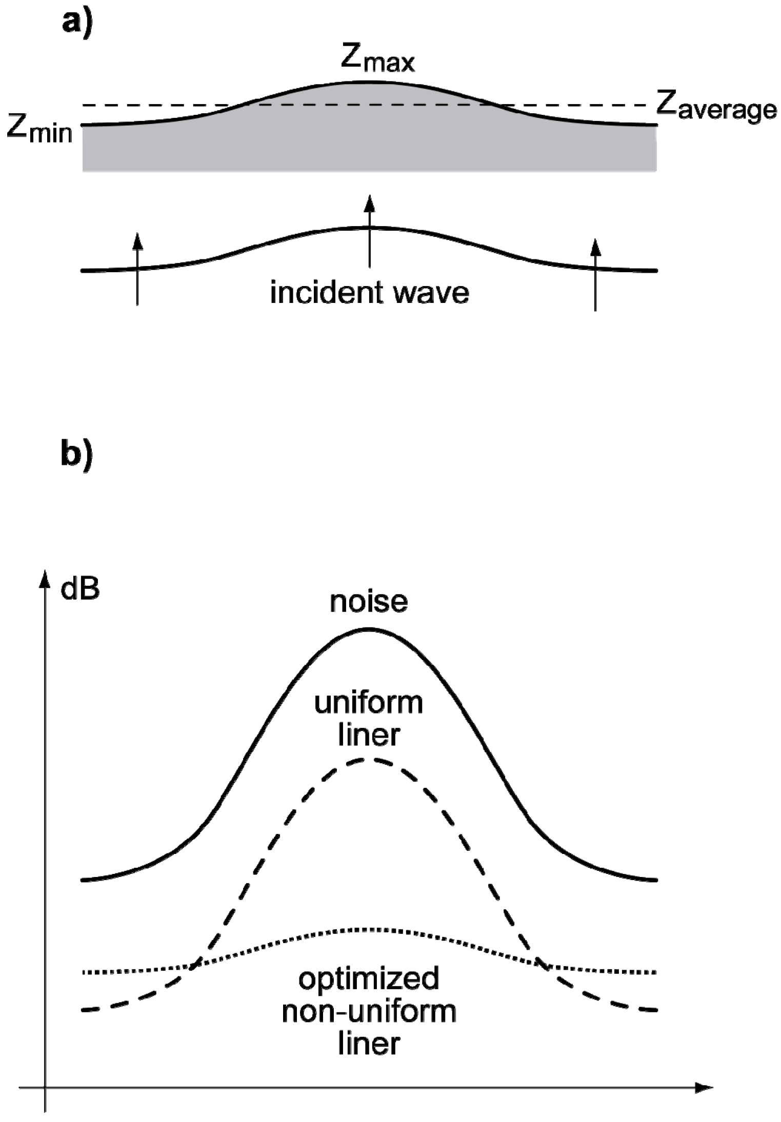
4.1.1. Non Uniform Duct Acoustic Liner

Although the acoustic liner is one of the oldest and most widely used of noise reduction methods, everywhere from factories and rooms to aircraft and other vehicles, progress is far from finished in enhancing its noise absorption characteristics. One of the main advantages of ducted engines in nacelles versus open rotors is not only the noise shielding by the nacelle, but also the availability inlet, exhaust and other duct interiors to install acoustic liners, that would be even more effective for buried engines. Although acoustic liners are extensively used [400,401,402,403,404,405] the physical mechanisms of noise reduction (Figure 11) are only partially understood and fairly complex: (i) the cavities below the holes can act as Helmhotz resonators absorbing sound; (ii) the bias flow out of the holes causes vortex shedding at the edges as does the grazing flow parallel to the wall; (iii) the shed vorticity and the vorticity in the shear flow in the duct both can contribute to further noise reduction. The noise reduction provided by acoustic liners involves several penalties: (i) increased drag, hence loss of thrust, increased fuel consumption and emissions; (ii) the weight, volume, cost, installation and eventual maintenance or refurbishment of the liner. For a given weight or area of acoustic liner it is desirable to maximize the noise reduction by using [400,401,402,403,404,405,406,407,408,409,410,411,412,413,414,415,416] non-uniform liners tailored (Figure 12) to have higher impedance in regions of peak noise levels and lower impedance in regions of low noise. This tailoring of the non-uniform impedance of the liner to the sound field, may lead to adaptive liners, since the noise field of an engine changes with flight condition.

4.1.2. Lobed and Chevron Nozzles

With the introduction of jet engines, namely the first generation turbojets, with a single flow stream of hot high-speed gases the jet noise became dominant. The first remedy was the adoption of multi-lobed nozzles that break the large turbulent eddies into smaller scales that emit less noise and decay faster. The lobed nozzle has penalties in drag, thrust and fuel consumption that could not be accepted as a long term solution. The turbofan with ever increasing by pass ratio provided a much better way of reducing noise by shielding the hot high-speed core jet by surrounding it with a slower, cooler by-pass flow, that also increases propulsion efficiency and decreases specific fuel consumption. The ever more stringent noise standards are not fully satisfied by the increasing by-pass ratio of turbofan engines, and the chevron nozzle achieves in a more clever way the same purpose as the lobed nozzle: enhanced mixing of jet and ambient flow and break-up of large into smaller vortices.
Figure 11. Acoustic liner with bias flow in a sheared boundary layer. The methods of noise reduction include: (i) reduction of noise at the source (Figure 16); (ii) passive attenuation or absorption (Figure 11 to Figure 14); (iii) cancellation by active noise or vibration control (Figure 14 and Figure 15); (iv) noise abatement flight procedures; (v) choice of a low-noise aircraft configuration (Figure 17 to Figure 19). The most widespread noise reduction measure is the acoustic liner, used to absorb sound in ducts, either in a cold stream like a fan inlet or in a hot stream like the turbine exhaust (Figure 16). An acoustic liner (Figure 11): (i) consists of a perforated wall with cavities below that act as resonators and sound absorbers; (ii) the noise may be absorbed or enhanced by shear flow in the wall boundary layer, that has a critical layer; (iii) the critical layer is eliminated by a bias flow out of the liner; (iv) the bias flow causes vortex shedding from the edges of the holes in the wall. Thus there are several noise reduction mechanisms [229] in a cold stream liner besides the temperature gradients in a hot stream liner. The noise reduction benefits of acoustic liners imply penalties in other areas (Figure 12).
Aerospace 02 00017 g011
Figure 12. Optimization of a non-uniform acoustic liner. As acoustic liner carries several penalties: (i) the weight, volume, cost, manufacturing and refurbishing of the lining; (ii) it increases drag, reduces thrust, increases fuel consumption and emissions; (iii) it penalizes all phases of flight, including cruise, for the sole purpose of reducing noise at take-off and landing. Thus an acoustic liner is a palliative or compromise solution, and should be optimized to give the best possible noise reduction with the least penalty by: (i) using the lining at the most effective locations; (ii) optimizing the impedance distribution (a) to absorb more sound at the peaks and less at the thoughts of the sound wave. For the same amount of liner material the optimized non-uniform liner [416] leads to a greater noise reduction by absorbing preferentially the noise peaks. The noise spectrum of an engine changes with thrust and flight condition and optimal noise attenuation would be achieved by an adaptive liner, with impedance distribution adjustable to the noise field to be absorbed. The adaptive acoustic liner is an intermediate step between a totally passive noise reduction (Figure 11) and active noise cancellation (Figure 14); thus it is one of the means of semi-active sound reduction (Figure 13 and Figure 14).
Aerospace 02 00017 g012
The chevron (and lobed) nozzle also makes the shear layer more irregular and turbulent increasing (Section 2.3.3) the spectral and directional broadening of sound. Since turbulence and shear flows are also a direct source of sound, besides a shielding against noise transmission, the chevron nozzle is a double-edged sword: it requires carefully optimization to ensure that shielding of noise from sources inside the jet has a greater effect than sound emission by the enhanced shear layer. A further advance [417] is the partial chevron nozzle (Figure 13) with: (i) chevrons over only a part of the periphery to reduce sound radiation to sensitive directions, like fly-over and sideline noise at take-off and landing; (ii) the angular sector of the nozzle with chevrons could be rotated to reduce noise radiation towards the aircraft cabin in cruise; (iii) the absence of chevrons in other angular sectors would allow sound to exit the jet in “harmless” directions.
Figure 13. Partial chevron nozzle with rotation. The partial chevron nozzle [417]: (i) has chevrons over the angular sectors where the noise disturbance is to be reduced by spectral and directional broadening (Figure 5 to Figure 9); (ii) there are no chevrons in other angular sectors, allowing sound to escape in other “harmless” directions. During take-off and landing the angular sectors with chevrons are used to reduce fly-over and sideline noise. In flight the partial chevron nozzle is rotated to reduce the sound transmission to the cabin. It is also possible to use shape memory alloys for the chevrons so that: (i) they extend into the stream in warm ambient air to reduce noise at take-off and landing; (ii) they retract in the cold stratospheric air so that there is no drag penalty in cruise flight.
Aerospace 02 00017 g013

4.1.3. Aerodynamic fairings and tailoring

The reduction of aerodynamic in addition to engine noise poses new challenges, some of which are more amenable to improvement than others. The cavity noise from open undercarriage wells can be mostly eliminated after landing gear extension, by partially closing the landing gear doors again or fairings over the cavity; this requires some detailed redesign of doors, legs and gaps but should not be a major issue. The reduction of noise from the extended landing gear may require aerodynamic fairings, to reduce vortex shedding from landing gear struts, shock absorbers, wheels, tyres and axles. These aerodynamic fairings would have to be compatible with retraction of the landing gear and closing of the landing gear bay doors after extension, leading to some design complexity and added weight.
The other sources of aerodynamic noise, such as the wakes of the wing, tailplane, and control and high-lift devices, lead to vorticity trailing behind the aircraft, that emits noise over an extended region, and thus is difficult to shield. One method of shielding would be creating a “fluid shield” (Figure 14) that is another weak shear layer to reflect some of the sound and broaden the spectrum and directivity of transmitted noise, like the chevron nozzle; however, as for the chevron nozzle, an additional shear layer would be another source of drag and noise, so the “pros” and “cons” would have to be carefully weighted. A less risky approach is to taylor the lift distribution in the wake of the wing and control surfaces to have a smooth vorticity profile, with the same total lift, but without sharp vorticity peaks or inversions.
Figure 14. Noise shielding by a fluid screen. The wake of an object can act as a “fluid shield” (a) partially reflecting sound and scattering the transmitted sound in a wider range of directions and frequencies like a shear layer (Figure 5) or turbulence (Figure 7). The wake could be made more irregular (c) to enhance the scattering effect by having undulations at the trailing edge of the object creating the wake (b) and also by using a slow flapping motion. The “fluid screen” would create another noise source due to the vorticity in the wake. However if it scatters a very strong acoustic signal like the noise of a prop-fan, the attenuation could be greater than the self-noise. The fluid screen would have to be placed so as to partially shield the noise source. The fluid shield could be created by a wing, tailplane, fin or winglet at a suitable position relative to the noise source.
Aerospace 02 00017 g014

4.2. Noise Mitigation Technologies

The generic noise mitigation technologies, like passive sound absorption (Section 4.2.1) and active noise and vibration reduction (Section 4.2.2) can be applied to aircraft, and can be complementary since the former is more effective at higher frequencies and the latter at low frequencies. Both techniques have limitations and penalties associated with extra weight or equipment and cost. The noise reduction at the source (Section 4.2.3) would be the preferred alternative when feasible.

4.2.1. Passive Attenuation or Absorption

The acoustic liner (Section 4.1.1) is an example of passive noise reduction device of widespread use. Passive noise absorption is effective mostly for high-frequencies or short wavelengths, that is shorter than the thickness of the sound absorbing layer; likewise noise shielding (Section 2.3.1) is only effective by obstacles larger than wavelength, and a shear layer is more effective at reducing jet noise (Section 2.3.3) for wavelengths smaller than its thickness. It could hardly be expected that a long wave could be shielded by a small obstacle, significantly attenuated by a thin absorbing layer or be subject to significant spectral and directional broadening by a small region of weak turbulence. Passive sound attenuation carries an extra weight, volume and material penalty, and should be optimized, like the non-uniform acoustic liner (Section 4.1.1). Since passive absorption is ineffective for low frequencies or long wavelengths active noise reduction may be necessary (Section 4.2.2).

4.2.2. Active Noise and Vibration Control

Sound can be produced by either aerodynamic noise sources or structural vibration, and thus active control can be effective both by suppressing vibration and noise [418,419,420,421,422,423,424,425,426,427,428,429,430,431]. The principle of active vibration and noise control is similar: to generate an oscillation with the same amplitude and opposite phase that exactly cancels the original disturbance. The requirements for implementation are also similar: (i) a set of sensors, e.g., microphones to detect noise or strain gauges to measure vibration; (ii) a control unit to process the inputs, and compute the response needed to exactly balance the disturbance; (iii) a set of effectors to produce the cancelling signal, such as anti-noise loudspeakers or vibration actuators; (iv) loudspeakers or actuators will need a power source, that may be the heaviest and bulkiest item, and whose weight and size may be reduced only by operating at high electrical voltage or high hydraulic pressure. Thus an active noise or vibration control system may be heavy, complex and expensive. It is more effective against discrete spectra (Figure 15) like propeller noise, than for continuous spectra, like jet noise. It works best for simple geometries like a duct for cancellation of unidirectional waves, and may be less effective in three dimensional geometries for which the interference of the signal and anti-signal can be a reinforcement as well as a cancellation depending on position. The limitations of passive (Section 4.2.1) and active (Section 4.2.2) noise reduction reinforce the desirability of the preferred solution: noise reduction at the source (Section 4.2.3).

4.2.3. Noise Reduction at the Source

Since passive noise reduction is not effective at low frequencies or long wavelengths and active noise reduction is limited for broadband noise, there is little alternative to noise reduction at the source for low-frequency broadband noise. Not only in this case, but also for any frequency (high, medium or low) and spectrum (tonal, broadband or a mixed superposition) noise reduction at the source appears as the ideal solution, without the weight and space penalties of passive absorbers and the equipment and power supply requirements of active control systems. However noise reduction at the source has limits: an aircraft needs lift to balance weight and the associated vorticity is an aerodynamic noise source. Similarly all propulsion methods have inherent noise sources (Figure 16) like the pressure loads on blades, the convected inhomogeneities due to combustion, or the vorticity shed from the trailing edges of airfoils of propellers, rotors or turbomachinery. Although these noise sources are unavoidable they can be reduced by suitable operational procedures (Section 4.3) or tailored by careful aircraft design (Section 5).
Figure 15. Active noise reduction in a cylindrical duct. Active noise reduction uses anti-noise sources or loudspeakers to cancel the existing noise field. Similarly active vibration suppression uses actuators to cancel existing vibrations. In both cases cancellation is achieved by generating a signal with the same amplitude and opposite phase. There are two paths for noise transmission: (i) the aerial path of sound waves that can be countered by active noise suppression; (ii) the structural path of vibrations that radiate sound can be countered by active vibration suppression. Examples of (i) include active noise reduction in an aircraft cabin, and of (ii) active suppression of the vibration of guide vanes in a jet engine. Another example of (ii) is suppression of vibration modes of a helicopter rotor. Active sound or vibration suppression involves additional equipment and power, and is most effective for discrete signals and simple geometries. The figure shows [429] tonal noise in a cylindrical duct without flow (aircraft cabin) or with flow (engine nacelle). Active noise control is used to cancel (a) the fundamental mode, (b) the first harmonic as well, (c) second harmonic and (d) all harmonics up to the fifth. As more tones are cancelled by active noise reduction there is a “spill-over” effect enhancing the background noise at higher frequencies; this “spill-over” effect can be countered by passive attenuation (Figure 11 and Figure 12) with additional penalties.
Aerospace 02 00017 g015
Figure 16. Noise sources and reduction in a turbofan engine. The diagram of a turbofan engine emphasizes the relation between its mode of operation and the noise sources: (i) the scarfed inlet with extended lower lip provides some shielding of fan noise in the forward direction; (ii) the chevron nozzle with undulations along the lip enhances the outer shear layer and reduces fan noise radiated rearwards; (iii) the acoustic liners in the fan duct and elsewhere (e.g., exhaust duct) absorb sound; (iv) the acoustic-shear waves in the fan inlet gain swirl in the compressor and turbine leading to acoustic-swirl waves; (v) these acoustic-vortical waves become acoustic-vortical-entropy waves in the combustion chamber; (vi) the active stators suppress vibrations and reduce noise radiation in the compressor and elsewhere; (vii) the jet noise is due to turbine wake and entropy noise is due to combustion gas patches, both convected in the hot high-speed core flow out of the inner chevron nozzle; (viii) the inner shear layer of the core jet, the outer shear layer of the fan flow, and the cold by-pass flow in between cause spectral and directional broadening of jet noise. In addition to engine noise there are aerodynamic noise sources maiinly vortex noise of turbulent wakes (besides cavity noise).
Aerospace 02 00017 g016

4.3. Noise Abatement Procedures

The aircraft noise disturbance can be reduced by suitable operating procedures [432,433,434,435,436,437,438,439,440,441,442,443], like approach to land with the engine at idle (Section 4.3.1) and thrust cut-back as soon as possible after take-off (Section 4.3.2) without compromising flight safety. The aim is to reduce the noise footprint, that is the area on the ground subject to noise levels higher than the threshold deemed acceptable. Depending on the local housing distribution around the airport relative to the runways, it may be possible to reduce the noise footprint by modified flight paths (Section 4.3.3) again within safety, certification and air traffic management (ATM) procedures.

4.3.1. Approach with Engine at Idle

The noise on approach to land may be reduced by keeping the engine at idle, thus reducing engine noise below aerodynamic noise, and making the latter another objective for noise reduction (Section 2.3.2). As with any flight procedure safety is paramount and cannot be compromised by other objectives, noise reduction or any other. Thus it must be possible to spool up the engines from idle to full power quickly enough to cope with any emergency, be it the failure of one engine, an atmospheric disturbance or a wake vortex [444,445,446,447,448,449,450] causing a large flight path deviation. An example of particularly serious atmospheric disturbance at landing is a windshear [451,452,453,454] due to a toroidal vortex close before the runway threshold, that leads to an abrupt change from headwind (runway overshoot) to tailwind (landing short of the runway) aggravated by a downflow, all adding together to a major lift loss. If the windshear is not detected in advance and avoided, once the aircraft flies into it the best survival strategy is: (i) to go into maximum angle-of-attack to minimize descent rate in case of ground impact; (ii) to spool-up to maximum thrust and increase speed and lift as fast as possible to counter the excess descent rate and reach the runway threshold at normal vertical speed or fly around.

4.3.2. Thrust Cut-Back at Take-Off

To reduce aircraft noise at take-off it is desirable to reduce the full engine thrust after the take-run to a lower cut-back thrust as soon as possible once in a stable climb, and able to counter emergencies like an engine failure and severe atmospheric disturbances like windshears and low-level jets. While ensuring the overriding requirement of flight satisfy, two options are available: (i) to reduce the thrust as soon as possible, thus mitigating noise, with the implication of a slower climb and longer time close to the ground, that may lead to a larger ground noise footprint; (ii) to keep a higher thrust longer, to achieve a higher climb rate, so that the shorter exposure to a higher noise level may lead to a smaller ground noise footprint. Thus optimizing the thrust cut-back point to minimize the noise footprint on the ground is a quite legitimate noise abatement procedure with no compromise on flight safety. The noise footprint on the ground matters not so much for its total area but rather for the fraction that is noise sensitive due to the housing distribution around the airport. Thus an additional noise reduction prospect is to tailor the noise footprint to avoid sensitive areas by adjusting flight paths.

4.3.3. Steep and Curved Flight Paths

The overriding importance of flight safety applies not only to the flight dynamics of the single aircraft at take-off and landing in any weather condition but also to the air traffic rules that ensure safe separation from other aircraft and local procedures to avoid mountains or other potential hazards. It is only within all these limits that flight paths may be adjusted, and steep, multi-segment or curved flight paths may not be available options. To the extent that a choice of flight path is available: (i) a steeper climb or descent can reduce the size of the noise footprint, while respecting the dynamics of safe flight; (ii) a “curved” flight path, or its discretized analogue of a segmented flight path, may avoid overflying sensitive areas, while keeping safe separation from other aircraft and hazardous ground. The extent to which flight path adjustment can lead to a reduction in overall noise exposure depends: (i) on the location of runways relative to the housing around the airport; (ii) on limitations in the choice of approach path due to terrain or ATM. This optimization can be quite specific to geography of a particular airport, and may reward the initiative of local authorities with less community noise and more efficient use of the airport. When all noise reduction measures and noise abatement procedures have been implemented, further noise reduction is possible only through improved low noise aircraft design (Section 5).

5. Novel Aircraft Configurations

Starting with the conventional Cayley-style tube-and-wing aircraft configuration and using all the available noise reduction technology is expected to lead to an overall noise reduction of about 10 dB as an average of the three certification measuring points. Making the aircraft inaudible outside the airport perimeter would require a noise reduction of about 30–40 dB. A noise reduction well in excess of 10 dB, even well short of 30 dB is most likely to be unachievable with a conventional aircraft configuration. This suggests the consideration of radical new aircraft configurations, such as a flying wing, buried engines or distributed propulsion (Section 5.1). The risks and maturation time may relegate these to longer term prospects, prompting the consideration of improvements to the current conventional aircraft (Section 5.2). A compromise proposal is an evolutionary low-risk design optimized differently for ducted and unducted propulsions (Section 5.3). The following discussion concerns only the overall aircraft configuration and its main implications [455,456,457,458,459,460,461,462].
There are dedicated research programs supported by governments in all countries and regions with major aircraft producers: Europe, United States, Russia, Japan, China, Brazil and Canada. Within Europe there are both national programs (France, Germany, Italy, The Netherlands, Sweden and the United Kingdom), bilateral and multilateral programmes and collective and international activities in the context of the European Union (EU) and others. These programs cover aircraft, helicopters, engines and their equipment. The two largest current aeronautical research programs are in the U.S. [463] and the EU [464]. Taking as example the EU the current aeronautics research program [464] is: (i) justified on the prediction [465] of air traffic growth of 3%–5% per year depending on the region of the world leading to a doubling de traffic volume every 15–25 years; (ii) includes specific quantitative performance targets for reductions in fuel consumption, noise and emissions and improvements in safety, security and timeliness [466]; (iii) covers industrial research projects (level 1), major integration efforts (level 2) and two joint undertakings (level 3) following [467,468] preceding work [469]. As in other countries and regions of the world [470] these aeronautical research projects cover a broad range of subjects in aeroacoustics research and development [471,472,473,474].
The successive EU aeronautics research programmers have steadily expanded in scope and resources since 1990, covering [21] several hundred projects, of which several dozen on aircraft noise research [475]. These projects have covered at industrial research (level 1) a variety of subjects including: (i) noise of conventional and advanced propellers [476,477]; (ii) tonal and broadband noise of helicopter rotors [478,479]; (iii) active noise reduction and vibration suppression [480,481]; (iv) jet and boundary-layer noise [482,483]; (v) acoustic fatigue [484]; (vi) aircraft design, testing and operations [485,486,487]; (vii) aircraft configurations maximizing shielding of engine noise [488,489]; (viii) effects of aircraft noise on the near-airport resident [490,491]. These advances in noise reduction have been integrated (level 2) into aircraft, aeroengine and helicopter design [492,493,494], contributing to (level 3) the joint undertakings [467,468], supported on a succession of four aeroacoustic research networks [495,496,497,498].
A significant portion of this vast research effort has concerned the so-called “novel” aircraft configurations, most often variations of (i) blended-wing-body (BWB) or flying wing [499] or (ii) the box-wing or joined wing [500]. In fact both concepts have a long history: (i) several dozen flying wing designs have been flown since the Horten gliders in the 1930’s, though only the Northrop B-2 Spirit stealth bomber reached production of 21 units; (ii) the box-wing was foreseen by Ludwig Prandtl as the optimum for maximizing lift-to-drag ratio and has only recently been flown in unmanned air vehicles (UAVs) and scale models. Among the vast research in these topics are mentioned some activities of two research groups, one on each side of the Atlantic, on related topics including: (i) optimization of aircraft design and performance [501,502,503,504]; (ii) control and stability of large flying wings [505,506,507,508,509]; (iii) structural and aerodynamic efficiency [510,511,512,513]; (iv) noise shielding and design [514,515,516,517,518,519,520]; (v) environmental issues en-route and near airports [521,522,523,524,525]. The present review on aircraft noise is intended to complement others [375], with a broad scope ranging from fundamental aeroacoustics to low-noise aircraft design. Also in some cases lesser known results have been detailed rather than those more widely reported, for example the acoustic boundary condition for axisymmetric sheared and swirling mean flow over an impedance wall [210,214] was mentioned explicitly (Equation (15)), with additional reference to the Ingard-Myers acoustic boundary condition [526,527] and its recent developments [528,529].

5.1. Radical New Designs

Among the many alternatives for radical new designs, the flying wing is chosen since it provides better noise shielding (Section 5.1.1) than say a joined wing. Further noise reduction may achieved replacing the engine nacelles with buried engines (Section 5.1.2) or using a distributed propulsion system (Section 5.1.3). The consideration of these more radical novel aircraft configurations cannot ignore the technological challenges and maturation that may defer these concepts to longer term prospects beyond the next generation.

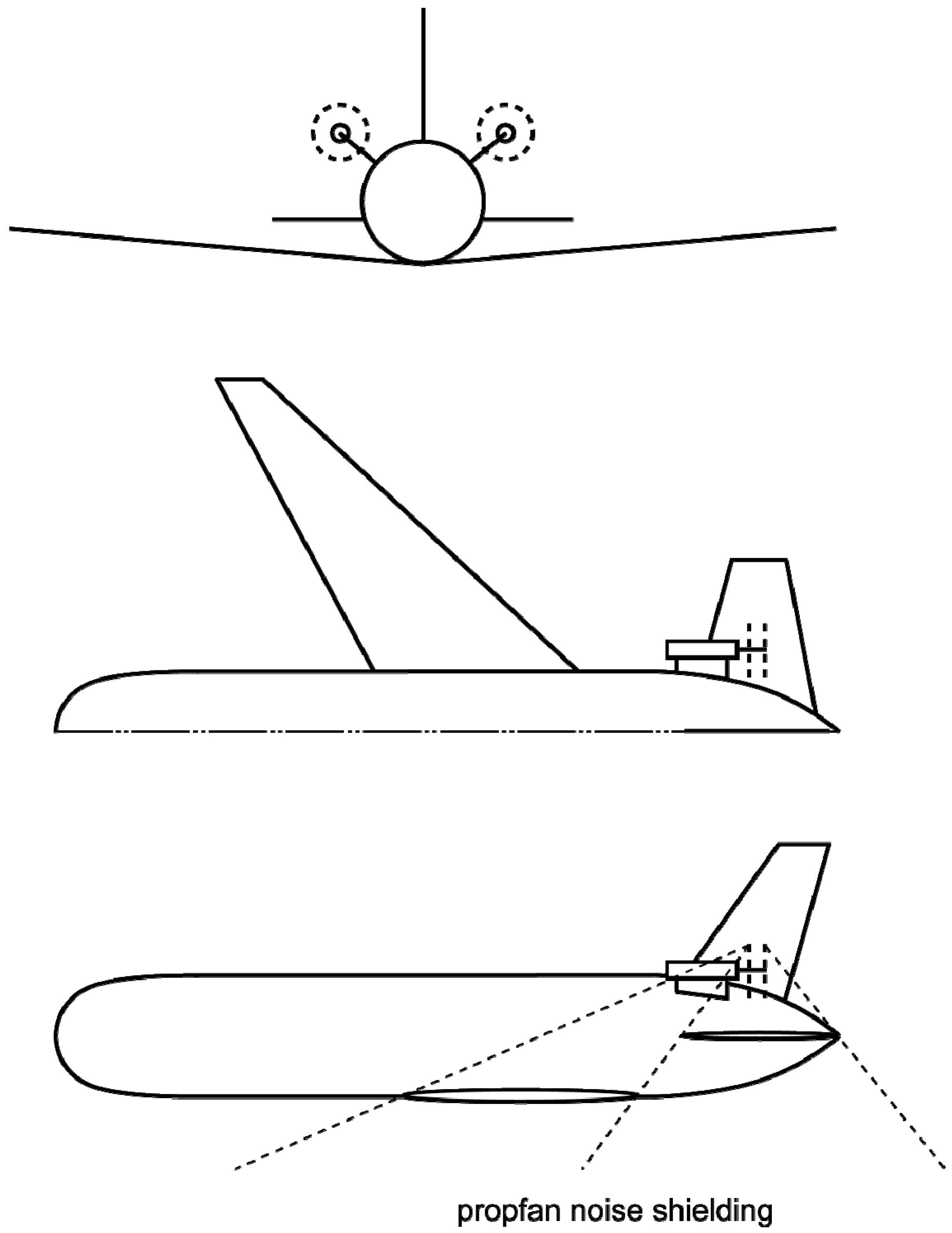
5.1.1. Flying Wing with Engine Nacelles

The flying wing has some fairly obvious attractions: (i) it offers the best overall lift-to-drag ratio and cruise efficiency, leading to the lowest fuel consumption in the absence of other limitations; (ii) the large cabin volume provides plenty of space for passengers and cargo, including an unprecedented amount of leisure areas. Placing the engines in underwing nacelles would add to direct noise a large wing reflecting area. Clearly the noise reduction option would be overwing engine nacelles (Figure 17), that provide excellent shielding of fan and turbine noise, and also some shielding of jet noise if the nacelles are sufficiently ahead of the wing trailing-edge. This engine location, while optimum for noise reduction, leads to other issues: (i) the engine nacelle in the accelerated flow above the wing would have higher drag at the same cruise speed, or force a lower cruising speed to avoid shock formation and wave drag during cruise flight; (ii) the engine would lie in the thick boundary layer in the aft section of the wing with serious flow distortion problems at the inlet; (iii) the high mounted engines would cause a pitch-down impling a possibly significant penalty in trim drag; (iv) the pitch down would oppose rotation at take-off requiring a high-angle of attack and a tall landing gear to avoid tail scrapes. All this could detract from the aerodynamic efficiency of the flying wing. Before considering other issues, even more daring engine configurations like buried engines (Section 5.1.2) or distributed propulsion (Section 5.1.3) are mentioned.
Figure 17. Flying wing: low-noise and efficiency compromises. The flying wing with overwing engine nacelles between the fins looks like the ideal low-noise configuration with shielding to the front, rear and sides; jet noise extending behind the nozzle is also shielded if the engine nacelle is well forward of the wing trailing-edge. Other attractive features of the configuration include (i) high cruise efficiency and (ii) large cabin volume. There are compromises: (i) the engine nacelles are in the high-speed flow above the wing and ingest the boundary layer; (ii) the non-circular fuselage makes pressurization less easy and outboard passengers are affected by rolling motions. The strong pitch-down of high mounted engines and lack of historic design and certification data add to the issues that may require a large-scale flying demonstrator before designing an operational airliner at least two generations ahead. Flush or buried engines add promise, problems and may need further large-scale proof-of-concept farther into the future.
Aerospace 02 00017 g017

5.1.2. Flush or Buried Engines

Changing from engines in overwing nacelles to flush engines would provide more noise shielding by reducing edge diffraction effects since the direct waves reaching the wing leading and trailing edges are weaker. Going further to buried engines would add to noise shielding by hiding the engine fan and turbine from line-of-sight: the possibility of acoustic lining of the inlet and exhaust ducts, would provide a high-level of sound absorption, so that aerodynamic noise would become the dominant noise source in all flight conditions. The improvement in noise reduction would come at the expense of aggravating other challenges: (i) the air intake of the flush mounted engine could lie entirely within the wing boundary layer; (ii) the buried engine would ingest mostly boundary layer flow except if the air intake was located at the leading edge with a long large diameter inlet duct. The large diameter of high by-pass ratio turbofans could make buried engines problematic. A semi-buried engine with some of the outer diameter protruding above the wing: (i) would lose some of the noise benefit of the burying, as part of the fan would be exposed to the free stream; (ii) the resulting force imbalance with the buried part, would imply significant flow distortion, could cause serious structural vibration problems, all of which would add to noise. Thus the option of buried engines may imply not the pair of large-diameter high-by-pass-ratio turbofans favoured by current airliner configurations but a rather a distributed propulsion system with small diameter engines (Section 5.1.3).

5.1.3. Distributed Propulsion System

A distributed propulsion system could consist of several small diameter turbofans. The requirement of low specific fuel consumption and hence high by-pass ratio with the limitation on fan diameter for buried engines, would restrict the thrust of each engine, and require a larger number of them. Moving towards a larger number of engines could increase cost and complexity, and goes against the current trend to highly efficient two engine airliners even for the long-haul overwater routes. The alternative of having fewer engines and ducting the exhaust to several nozzles could lead to high pressure losses and cooling problems for hot high-speed jets. The experience with ducting jet engine exhausts with V/STOL aircraft prototypes since the 1950’s was not encouraging and demonstrated significant thrust losses.
Whatever the engine option, overwing nacelles (Section 5.1.1), buried engine (Section 5.1.2) or distributed propulsion (Section 5.1.3) the flying wing raises other issues: (i) the pressurization of the non-cylindrical fuselage would require either a division into joined cylindrical tubes or a more complex support structure; (ii) the wide fuselage would place passengers near the axis far from windows and passengers further outboard would be more sensitive to rolling motions and accelerations. Other issues like stability, control and handling qualities could be resolved, but point towards a more general issue: a lack of design experience, historic data and maturity in the integration of novel aircraft configuration, that could require a large-scale flying demonstrator; even if financing could be found, the full scale operational aircraft would be at least one more generation later, assuming that the demonstrator had provided enough confidence for aircraft designers and certification authorities. These are major assumptions, and maybe significant noise reduction cannot wait two generations or more. Something must be done to significantly reduce aircraft noise in the meantime without going too far beyond mature and certifiable technology. This suggests considering improvements to the classical current aircraft configuration (Section 5.2).

5.2. Evolutions of the Conventional Configuration

In order to make feasible the application in the next generation of aircraft, that must be based on available data bases and consolidated certification experience, it is more prudent to consider evolutions of the current conventional tube-and-wing aircraft configuration with greater noise reduction potential. Two examples are: (i) the U-tail with engines in between to achieve better noise shielding (Section 5.2.1); (ii) engine nacelles joining the trailing-edge of a low wing to the leading-edge of a low tailplane (Section 5.2.2). Besides evolution of airframe configurations, that affect aerodynamic noise and shielding of engine noise, the role of the engine as noise source implies considering the evolution of propulsion systems ranging from the contrarrotating open propulsion (Section 2.1.3) to the variable-cycle turbofan (Section 5.2.3).

5.2.1. Engines between a U-Tail

A twin engine aircraft with engine nacelles between a U-tail may be considered an evolution of rear fuselage nacelle moved upwards between two fins and a tailplane to achieve better noise shielding: (i) the shielding of fan noise is provided mainly by the wing and fuselage in the most important forward direction, although the distance between the wing mounted low in the fuselage and the engine high above the tail limits the angle of blockage of sound; (ii) the twin fins and tailplane shield some of the turbine noise if the engine nacelle is mounted entirely forward of their trailing-edge. The noise shielding effects are limited: (i) by the length of the engine nacelles exceeding the chord of the tailplane and fins, so that they cannot shield both fan and turbine noise, but only turbine noise, leading fan noise shielding by the fuselage and wing; (ii) even if the engine nacelle is placed sufficiently forward to have shielding to the turbine noise by the tailplane and fins, the jet noise that extends further downstream cannot be shielded. The engines mounted high above the fuselage, to be clear of its boundary layer, create a significant pitch-down moment that may lead to a larger trim drag in cruise than for the configuration with rear nacelles at the fuselage sides. These two aspects are addressed by the next configuration with engine nacelles joining a low wing to a low tailpane (Section 5.2.2).

5.2.2. Nacelle Joining Wing to Tailplane

Another evolution of the conventional aeroplane is to keep the low wing, move the tailplane to an equally low position at the bottom of the fuselage with winglets as fins, and use the engine nacelle to join the wing to the tailplane, with the air intake above the trailing edge of the wing and the exhaust nozzle above the leading edge of the tailplane. This configuration does not have the large pitch-down moment of the engines above the U-tail and might have instead a small pitch-up moment since the thrust axis is moved from far above to slightly below the line of the center of gravity. The air inlet over the leading-edge of the wing provides good shielding of fan noise but ingests the boundary layer of the wing at its maximum thickness at the trailing edge. The exhaust nozzle over the leading edge of the tailplane provides good shielding of turbine noise, and also of jet noise as far as the jet exhaust flows over the tailplane. There lies a problem, namely the thermal stresses on the tailplane due to the hot jet exhaust flowing directly over its surface. An additional problem, also serious, is that the low mounted tailplane lies in the wake of the low-mounted wing, with a high risk of flow separation and loss of pitch control authority that not even boundary layer control may overcome. Clearly the engine installation is the major factor in low-noise aircraft configurations benefiting from noise shielding, suggesting a preliminary reconsideration of propulsion alternatives (Section 5.2.3) before considering improved low-noise aircraft designs (Section 5.3).

5.2.3. Variable-Cycle Engines

Two of the main possible turbofan evolutions are the unducted high by-pass ratio turbofan or counterotating open rotor (Section 2.1.3) and the variable-cycle engine housed in a nacelle (Section 5.2.3). The variable-cycle turbofan uses a third flow stream either to augment the hot core flow or the cold fan by-pass flow. The variable-cycle engine is desirable to combine high thrust and low drag for supersonic flight with low fuel consumption for long range in military aircraft. The variable-cycle engine would probably be essential for a civil supersonic transport, to combine efficient supersonic flight with acceptable noise at take-off and landing. The ability of the variable-cycle engine to have a wider range of jet exhaust velocities could be used in a subsonic aircraft to retain current jet exhaust velocities in cruise flight combined with low exhaust speed for low-noise at take-off and landing. However the cost and complexity of the variable-cycle engine may not be justified solely by reducing jet exhaust velocities and noise in low speed flight. A more likely prospect is the contrarotating open propulsion that offers significant reduction in fuel consumption and emissions due the very high by-pass ratio if the noise of the open rotors and BVI interactions proves to be acceptable: it should at least meet satisfy current noise standards, and a margin to accommodate future more stringent noise regulations is necessary as well. Therefore both ducted and unducted propulsions are considered next as they may lead to different low-noise aircraft configurations (Section 5.3).

5.3. Low-Noise Cruise-Efficient Aircraft

At the beginning of the jet age aircraft noise was an afterthought: hence the multi-lobe nozzle used to reduce jet noise at the expense of drag, thrust and fuel consumption. The remarkable technical achievement of Concorde and the noise issues that it raised, contributed to the consideration of noise earlier in the aircraft and engine design process, as is nowadays the case. The next grand step of conceiving low-noise aircraft configurations poses greater challenges since there are many other objectives to be met, and not all are easily compatible. A simple demonstration is to conceive an aircraft optimized for low take-off and landing noise: it would resemble a glider, with an unwept wing of high aspect ratio for low stall, take-off and landing speeds, hence low aerodynamic noise, and an engine with low jet exhaust speed from relatively slow rotating turbomachinery. The implications for cruise efficiency would be dire: low thrust, high drag, high fuel consumption, high emissions, low speed and long duration flights. The design targets for low noise at aircraft can be at odds with high cruise efficiency, and the main challenge is to achieve the former without compromising the latter. Thus high-cruise efficiency is one of the multiple requirements to be considered (Section 5.3.1) for a low-noise aircraft configuration, that may differ for ducted engines in nacelles (Section 5.3.2) and open rotors (Section 5.3.3) since they pose different challenges. An additional issue is combining low noise with low emissions, that would justify a separate discussion.

5.3.1. Design Requirements and Constraints

The design requirements on a low-noise aircraft configuration are mainly not to compromise the essential aspects of a long list of other design objectives, of which some are highlighted: (i) low-noise at take-off and landing near airports cannot compromise cruise efficiency leading to lower speed and shorter range, higher fuel consumption and emissions, as this would be entirely counter-productive from both the environmental and economic points-of-view, and would spend more non-renewable energy resources to provide a lower quality of air transportation; (ii) the increasing air traffic demand and associated pressure for significant noise reductions should be addressed by the next generation of aircraft if severe operating restrictions are to be avoided; (iii) radically different aircraft configurations, even if promising or enticing, are at least one large-scale demonstrator and two generations away for operational aircraft; (iv) a low-noise aircraft for the next generation needs to be based on available mature technology that can gain the confidence of designers and the endorsement of certification authorities. The challenge is not to imagine the remotely possible, but to find the best use of what we know to improve what we have.

5.3.2. Configuration I: For a Ducted Turbofan

The proposed low-noise aircraft configuration for ducted turbofans critically depends (Figure 18) on the position of the engine nacelle relative to the wing and tailplane: (i) the air intake is above the trailing-edge of the low-mounted wing that provides shielding of fan noise; (ii) the exhaust nozzle is above the leading-edge of the mid-set tailplane that provides shielding of turbine noise and some jet noise; (iii) the mid-set tailplane is not in the wake of the wing and the engine nacelle is higher up on the fuselage so that the hot jet exhaust does not impinge on the tailplane. This optimal positioning of the engine nacelle relative to the wing and tailplane inevitably raises some issues that do not appear too serious: (i) the engine nacelle is not entirely behind the pressurized fuselage section, so it must be at least partially armoured to withstand turbine blade failure; (ii) cabin noise due to the fan may require mitigation by anti-noise in some seat rows; (iii) the pitch-down moment may be a little stronger due to the higher mounting of the engines. The aerodynamic noise should be minimized by direct lift control of the wing, and the undercarriage may need fairings. Altogether these are modest penalties for lower airport noise with no degradation on cruise efficiency. This configuration may not apply to open rotors, if they are not allowed to lie at the sides of a pressurized fuselage section: the risk of blade failure and excessive cabin noise may require a different positioning (Section 5.3.3).
Figure 18. Low-noise cruise-efficient aircraft configuration I: turbofan. The lowest-noise aircraft configuration within mature technology and historic data available for the next generation could have: (i) a conventional fuselage with low-wing and mid-set tailplane; (ii) a carefully positioned engine nacelle to maximize shielding of forward noise by the wing and shielding of aft noise by the tailplane. Jet noise and aerodynamic noise need to be minimized by careful nozzle design and wing lift distribution. The inevitable penalties seem tractable: (i) armouring of the engine nacelle on the fuselage side against uncontained turbine blade failure; (ii) countering the moderate pitch-down of relatively high-mounted engines in all flight phases. Other configurations like engines between a U-shaped empennage or an engine nacelle joining the wing to the tailplane may have more severe issues without providing better noise shielding.
Aerospace 02 00017 g018

5.3.3. Configuration II: For Open Rotors

The fuel consumption advantages of the open rotor lead to multiple challenges regarding noise and installation effects: (i) the torque cancelling counterotation enhances BVI noise; (ii) there is no nacelle for noise shielding or use of acoustic liners; (iii) certification authorities may require that the open rotor be aft of the pressurized fuselage section, to safeguard the case of blade failure, leaving no choice of location other than the aft end of the fuselage; (iv) noise shielding by the far-away wing is of limited help; (v) trying to fit two large open rotors between a U-tail might cause serious structural problems. With so many issues and constraints the possible choices (Figure 19) are: (i) use the tailplane at a mid-set position, out of the wake of the low mounted wing to shield noise from the open rotors; (ii) for this to be moderately effective the tailplane must have a large chord with the rotors above to shield both forward and aft noise; (iii) the moderate tailplane area may lead to a small aspect ratio, as an inevitable compromise; (iv) the pitch-down moment of the high mounted aft open rotors and the limited lift-to-drag ratio of the tailplane with large chord and short span imply that pitch balance should result from both wing and tailplane lift; (v) this could be obtained by a reverse canard configuration (Figure 20) with a swept forward wing with lift center not far ahead of the center of gravity; (vi) the swept forward wing has advantadges regarding stall, but raises aeroelastic issues that could be reduced by a joined wing.
Figure 19. Low-noise cruise-efficient aircraft configuration II: open-rotor. Certification authorities may require the open-rotor to be placed behind the pressurized section of the fuselage requiring (Figure 19) leading a different configuration from the airliner powered by turbofans in nacelles (Figure 18). The lack of a nacelle for noise shielding and installation of acoustic liners complicates further the noise problem aggravated by the BVI noise of one propeller contrarotating in the wake of another. The fuel consumption benefits may be large enough to allow a moderate compromise to reduce noise and still come out with a significant reduction in fuel burn. The only noise shielding option (other than fluid screens (Figure 14) that create noise and need structure) is a tailplane with large chord and moderate span. There is no spectral or directional broadening of sound by shear layers, because there is no nacelle, and creating shear layers around the rotors (Figure 5) would require unwanted structure upstream and create another noise source. The only option seems shielding by a tailplane with large chord to cover forward and aft noise, and enough span to shield sideline noise. A large tailplane with low aspect ratio is far from ideal for lift-to-drag ratio or pitch trim. This could be partially compensated by a reverse canard configuration (Figure 20) that uses pitch trim to add to the lift of the wing.
Aerospace 02 00017 g019
Figure 20. Pitch trim with lift augmentation in the reverse canard configuration. In a conventional aircraft (a) with aerodynamic center (a.c.) behind the center of gravity (c.g.) pitch trim reduces overall lift (a); this is particularly undesirable with a tailplane with low lift-to-drag ratio designed to shield open rotor noise. A conventional canard (b) uses pitch trim to add to wing lift, but does too little for shielding open rotor noise, unless a third surface is placed at the rear as a non-lifting, drag-only addition. It is possible to have pitch trim add to wing lift in a reverse canard configuration (c) with a.c. ahead of the c.g. This may require a forward swept wing, which delays stall propagation from inboard to outboard sections. The aeroelastic and weight implications of the swept-forward wing have may be reduced by a joined wing. The reverse canard configuration (c) provides pitch trim which augments lift with a tailplane that shields open rotor noise. The two aircraft configurations with turbofans in nacelles (Figure 18) or open rotors (Figure 19) rely on the aircraft structure to shield noise. Another approach is to use a fluid screens for noise shielding (Figure 14).
Aerospace 02 00017 g020
A conventional sweptback wing with center of lift behind the center of gravity can be retained with a larger tailplane that provides more shielding and achieves pitch trim with more cruise drag and lift loss. The forward and aft swept wings provide different noise shielding patterns with regard to fan noise; the positioning of the wing affects not only fan noise shielding but also airplane stability. If flight stability or aerodynamic efficiency or other considerations prevent noise shielding by the wing or tailplane the last resort for noise shielding would be to use a “fluid screen” (Figure 14): (i) a turbulent wake is created around the noise source such as the prop-fan; (ii) although the wake itself is an additional noise source the attenuation of strong noise sources inside as for a shear layer (Section 2.3.3) could be the dominant effect. The “noise shielding screen” could be made more irregular using as generator a corrugated and flapping surface. Some of the full efficiency of the propfan might have to be sacrificed to noise reduction measures while keeping a positive overall balance.

6. Conclusions

The present paper has addressed some of the issues relating to aircraft noise at airports across the full “cradle to grave” spectrum of aeroacoustics research (Section 2), through environmental (Section 3) and operational (Section 4) aspects to aircraft design (Section 5). The review of aeroacoustics research (Section 2) has focused on some aspects not widely known but that could have considerable impact such as: (i) the existence of two alternative theories of aerodynamic noise [1,2,3,4,5,6,7,8,9] and [62,63,64,65,66,67,68]; (ii) the coupling of sound with vortical and entropy modes in jet engines [186,187,188,189,190,191,192,193,194,195,196,197,198,199,200,201,202,203,204,205,206,207,208,209,210,211,212,213,214,215]. The account on sound transmission from the aircraft noise sources to the interior of the near airport resident (Section 3) has included: (i) the spectral and directional broadening of noise [255,256,257,258,259,260,261]; (ii) the psychoacoustic distinctions between noise components. The noise mitigation measures (Section 4) mentioned include: (i) optimization of non-uniform acoustic liners [406,407,408,409,410,411,412,413,414,415,416] and use of partial chevron nozzle [417]; (ii) low noise operating procedures [432,433] consistent with flight safety and air traffic management rules [444,445,446,447,448,449,450,451,452,453,454]. Both can reduce noise exposure near airports [346,347,348,349,350,351,352,353,354,355,356,357,358,359,360,361,362,363,364,365] and their effects [366,367,368,369,370,371,372,373,374,375,376,377,378,379,380,381,382,383]. The proposed low-noise aircraft designs (Section 5) differ for ducted engines in nacelles (Figure 18) and open rotors (Figure 19) to: (i) retain uncompromised cruise efficiency; (ii) rely only on mature technology certifiable for the next generation of aircraft. The legends for the diagram and 20 figures include additional details relative to the passing references in the text.

Acknowledgments

This work was performed in the content of LAETA (Laboratory Associatioin for Energy, Transport and Aeronautics) of FST (Foundation for Science and Technology) of Portugal.

Conflicts of Interest

The author declares no conflict of interest.

References

  1. Lighthill, M.J. On sound generated aerodynamically: I. General theory. Proc. R. Soc. Lond. 1952, A211, 564–587. [Google Scholar] [CrossRef]
  2. Lighthill, M.J. On sound generated aerodynamically: II. Turbulence as source of sound. Proc. R. Soc. Lond. 1954, A222, 1–32. [Google Scholar]
  3. Lighthill, M.J. On sound generated aerodynamically. Bakerian Lecture. Proc. R. Soc. Lond. 1961, A267, 147–182. [Google Scholar]
  4. Lighthill, M.J. Waves in Fluids; Cambridge Univerysity Press: Cambridge, UK, 1978. [Google Scholar]
  5. Campos, L.M.B.C. Modern trends in research on waves in fluids. Part I: Generation and scattering by turbulent and inhomogeneous flows. Portug. Phys. 1983, 14, 121–143. [Google Scholar]
  6. Campos, L.M.B.C. On waves in gases. Part I: Acoustics of jets, turbulence and ducts. Rev. Mod. Phys. 1986, 58, 117–182. [Google Scholar] [CrossRef]
  7. Curle, N. The influence of solid boundaries upon aerodynamic sound. Proc. Roy. Soc. Lond. 1955, A231, 505–513. [Google Scholar] [CrossRef]
  8. Ffowcs-Williams, J.E.; Hawkins, D.L. Sound generation by turbulence and surfaces in arbitrary motion. Phil. Trans. Roy. Soc. Lond. 1968, A264, 321–383. [Google Scholar]
  9. Campos, L.M.B.C.; Lau, F.J.P. On sound generation by moving surfaces and convected sources in a flow. Int. J. Aeroacoustics 2009, 11, 103–136. [Google Scholar] [CrossRef]
  10. Rayleigh, J.W.S. The Theory of Sound, 2nd ed.; Dover: Mineola, NY, USA, 1945; Volume 2. [Google Scholar]
  11. Lamb, H. Dynamical Theory of Sound; Dover: Mineola, NY, USA, 1960. [Google Scholar]
  12. Morse, P.M.; Ingard, K.U. Theoretical Acoustics; McGraw-Hill: Princeton, NJ, USA, 1968. [Google Scholar]
  13. Pierce, A.D. Acoustics; McGraw-Hill: New York, NY, USA, 1981. [Google Scholar]
  14. Dowling, A.P.; Ffowcs-Williams, J.E. Sound and Sources of Sound; Ellis Harwood: London, UK, 1983. [Google Scholar]
  15. Goldstein, M.E. Aeroacoustics; McGraw-Hill: New York, NY, USA, 1986. [Google Scholar]
  16. Howe, M.S. Hydrodynamics and Sound; Cambridge University Press: Cambridge, UK, 2006. [Google Scholar]
  17. Crighton, D.G.; Flowcs-Williams, J.E. Sound generation by turbulent two-phase flow. J. Fluid Mech. 1969, 36, 585–603. [Google Scholar] [CrossRef]
  18. Glauert, H. Airfoil and Airscrew Theory; Cambridge University Press: Cambridge, UK, 1936. [Google Scholar]
  19. Blake, W.K. Mechanics of Flow-Induced Sound and Vibration I/II; Academic Press: New York, NY, USA, 1986. [Google Scholar]
  20. Hubbard, H.H. Aeroacoustics of Flight Vehices; Acoustical Society of America: New York, NY, USA, 1995. [Google Scholar]
  21. Martin-Hernandez, J.M. Advances in Acoustic Technology; Wiley: London, UK, 1994. [Google Scholar]
  22. Campos, L.M.B.C. On some recent advances in aeroacoustics. Int. J. Acoust. Vib. 2004, 11, 27–45. [Google Scholar]
  23. Campos, L.M.B.C. On waves in fluids: Some mathematical, physical and engineering aspects. In Progress in Industrial Mathematics ECMI; Springer: Heidelberg, Germany, 2006; pp. 73–105. [Google Scholar]
  24. Gutin, L. On the Sound Field of a Rotating Propeller; National Advisory Committee for Aeronautics (NACA): Washington, DC, USA, 1948. [Google Scholar]
  25. Hubbard, H.H. Sound from Dual-Rotating and Multiple Single Rotating Propellers; National Advisory Committee for Aeronautics (NACA): Washington, DC, USA, 1948. [Google Scholar]
  26. Hanson, D.B. Helicoidal surface theory for harmonic noise of propellers in the far field. AIAA J. 1980, 18, 1213–1220. [Google Scholar] [CrossRef]
  27. Hanson, D.B. Influence of propeller design parameters on far-field harmonic noise in forward flight. AIAA J. 1980, 18, 1313–1319. [Google Scholar] [CrossRef]
  28. Dahan, C.; Avezard, L.; Guillien, G.; Malarmey, C.; Chombard, J. Propeller light aircraft noise at discrete frequencies. AIAA J. Aircr. 1981, 18, 480–486. [Google Scholar] [CrossRef]
  29. Hanson, D.B. Compressible helicoidal surface theory for propeller aerodynamics and noise. AIAA J. 1983, 21, 881–889. [Google Scholar] [CrossRef]
  30. Hanson, D.B. Near-field frequency-domain theory for propeller noise. AIAA J. 1985, 23, 499–504. [Google Scholar] [CrossRef]
  31. Farassat, F. Prediction of advanced propeller noise in the time domain. AIAA J. 1986, 24, 578–584. [Google Scholar] [CrossRef]
  32. Tam, C.K.W.; Salikuddin, M. Weakly non-linear acoustic and shock wave theory of the noise of advanced high-speed turbo propellers. J. Fluid Mech. 1986, 164, 127–154. [Google Scholar] [CrossRef]
  33. Farassat, F.; Dunn, M.H. Advanced turboprop noise prediction based in recent theoretical results. J. Sound Vib. 1987, 59, 53–89. [Google Scholar] [CrossRef]
  34. Gounet, H.; Lewy, S. Prediction of prop-fan noise by a frequency domain scheme. AIAA J. 1988, 25, 428–435. [Google Scholar]
  35. Tam, C.K.W.; Salikuddin, M.; Hanson, D.B. Acoustic interference of counter-rotation propellers. J. Sound Vib. 1988, 124, 357–366. [Google Scholar] [CrossRef]
  36. Stuff, R. Noise field of a propeller with angular inflow. AIAA J. 1988, 26, 777–782. [Google Scholar] [CrossRef]
  37. Jou, W.H. Supersonic propeller noise in a uniform flow. AIAA J. 1989, 62, 385–390. [Google Scholar] [CrossRef]
  38. Mani, R. The radiation of sound from a propeller at angle of attack. Proc. Roy. Soc. Lond. 1990, 431, 203–218. [Google Scholar] [CrossRef]
  39. Envia, E. Asymptotic theory of supersonic propeller noise. AIAA J. 1994, 32, 239–246. [Google Scholar] [CrossRef]
  40. Campos, L.M.B.C. On the influence of angle-of-attack on far-field propeller noise. ASME J. Acoust. 1999, 121, 50–58. [Google Scholar] [CrossRef]
  41. Lowson, M.V. Basic mechanism of noise generation by helicopters, V/STOL aircraft and ground effect machines. J. Sound Vib. 1966, 3, 454–466. [Google Scholar] [CrossRef]
  42. Leverton, J.W.; Taylor, F.W. Helicopter blade slap. J. Sound Vib. 1966, 4, 345–357. [Google Scholar] [CrossRef]
  43. Lowson, M.V.; Ollerhead, J.B. A theoretical study of helicopter rotor noise. J. Sound Vib. 1969, 9, 197–222. [Google Scholar] [CrossRef]
  44. Hawkings, D.L.; Lowson, M.V. Theory of open supersonic rotor noise. J. Sound Vib. 1974, 36, 1–20. [Google Scholar] [CrossRef]
  45. Aravamudan, K.S.; Lee, A.; Harris, W.L. A simplified Mach number scaling law for helicopter rotor noise. J. Sound Vib. 1978, 57, 555–570, Erratum in 1979, 62, 595–597. [Google Scholar]
  46. Farassat, F. Linear acoustic formulas for calculation of rotating blade noise. AIAA J. 1981, 19, 1122–1130. [Google Scholar] [CrossRef]
  47. Farassat, F.; Martin, R.M. A note on the tip noise of rotating blades. J. Sound Vib. 1983, 86, 449–453. [Google Scholar] [CrossRef]
  48. Brooks, T.F.; Marcolini, M.A. Airfoil tip vortex formation noise. AIAA J. 1986, 24, 246–252. [Google Scholar] [CrossRef]
  49. Schmitz, F.H.; Yu, Y.H. Helicopter impulsive noise: Theoretical and experimental status. J. Sound Vib. 1986, 109, 361–422. [Google Scholar] [CrossRef]
  50. Brooks, F.T.; Marcolini, M.A.; Pope, D.S. A directional array approach for the measurement of rotor noise source distributions with controlled spatial resolution. J. Sound Vib. 1987, 112, 192–197. [Google Scholar] [CrossRef]
  51. George, A.R.; Lyrintzis, A.S. Acoustics of transonic blade-vortex interactions. AIAA J. 1988, 26, 769–776. [Google Scholar] [CrossRef]
  52. Unal, A.; Tung, C. Two generalized fields and their governing equations applied to helicopter acoustics. Acustica 1989, 69, 22–25. [Google Scholar]
  53. Lowson, M.V. Progress towards quiter civil helicopters. Aeron. J. 1991, 2, 209–223. [Google Scholar]
  54. Campos, L.M.B.C.; Macedo, C.M. On the predidiction of the broadband noise of helicopter from the impulse component. J. Acoust. 1992, 5, 531–542. [Google Scholar]
  55. Dunne, R.C.; Howe, M.S. Wall-bounded blade-tip vortex interaction noise. J. Sound Vib. 1997, 202, 605–618. [Google Scholar] [CrossRef]
  56. Doak, P.E. Acoustic radiation from a turbulent fluid containing foreign bodies. Proc. R. Soc. Lond. 1960, A254, 129–145. [Google Scholar] [CrossRef]
  57. Lowson, M.V. The sound field for singularities in motion. Proc. R. Soc. Lond. 1965, 286, 559–572. [Google Scholar] [CrossRef]
  58. Lowson, M.V. Theoretical analysis of compressor noise. J. Acoust. Soc. Am. 1968, 47, 371–385. [Google Scholar] [CrossRef]
  59. Ffowcs-Williams, J.E.; Hawkings, D.L. Theory relating to the noise of rotating machinery. J. Sound Vib. 1969, 10, 10–21. [Google Scholar] [CrossRef]
  60. Goldstein, M.E. Unified approach to aerodynamic sound generation in the presence of solid boundaries. J. Acoust. Soc. Am. 1974, 56, 497–506. [Google Scholar] [CrossRef]
  61. Farassat, F. Discontinuities in aerodynamics and aeroacoustics: The concept and applications of generalized derivatives. J. Sound Vib. 1977, 2, 165–193. [Google Scholar] [CrossRef]
  62. Powell, A. Theory of vortex sound. J. Acoust. Soc. Am. 1964, 36, 177–195. [Google Scholar] [CrossRef]
  63. Candel, S.M. Analytical Studies of Some Acoustic Problems of Jet Engines. Ph.D. Thesis, California Institute of Technology, Pasadena, CA, USA, 1972. [Google Scholar]
  64. Morfey, C.L. Amplification of aerodynamic noise by convected flow inhomogeneities. J. Sound Vib. 1973, 31, 391–397. [Google Scholar] [CrossRef]
  65. Ffowcs-Williams, J.E.; Howe, M.S. The generation of sound by density inhomogeneities in low Mach number nozzle flows. J. Fluid Mech. 1975, 70, 605–622. [Google Scholar] [CrossRef]
  66. Howe, M.S. On generation of sound by aerodynamic sources in inhomogeneous steady flow. J. Fluid Mech. 1975, 67, 597–610. [Google Scholar] [CrossRef]
  67. Howe, M.S. Contribution to the theory of aerodynamic sound with application to excess jet noise and the theory of the flute. J. Fluid Mech. 1975, 72, 625–673. [Google Scholar] [CrossRef]
  68. Campos, L.M.B.C. On the emission of sound by an ionized inhomogeneity. Proc. R. Soc. Lond. 1978, A351, 65–91. [Google Scholar] [CrossRef]
  69. Campos, L.M.B.C. On the fundamental acoustic mode in variable area, low Mach number nozzles. Prog. Aerosp. Sci. 1985, 22, 1–27. [Google Scholar] [CrossRef]
  70. Campos, L.M.B.C. On linear and non-linear wave equations for the acoustics of high-speed potential flows. J. Sound. Vib. 1986, 110, 41–57. [Google Scholar] [CrossRef]
  71. Campos, L.M.B.C. On 36 forms of the acoustic wave equation in potential flows and inhomogeneous media. Appl. Mech. Rev. 2007, 60, 149–171. [Google Scholar] [CrossRef]
  72. Campos, L.M.B.C. Complex Functions with Application to Flows and Fields; CRC Press: Boca Raton, FL, USA, 2011. [Google Scholar]
  73. Lamb, H. Hydrodynamics, 6th ed.; Cambridge University Press: Cambridge, UK, 1932. [Google Scholar]
  74. Milne-Thomson, L.M. Theoretical Aerodynamics; Dover: Mineola, NY, USA, 1966. [Google Scholar]
  75. Campos, L.M.B.C. Transcendental Representations with Applications to Solids and Fluids; CRC Press: Mineola, NY, USA, 2012. [Google Scholar]
  76. Bassett, A.B. A Treatise on Hydrodynamics; Dover: Mineola, NY, USA, 1961; Volume 2. [Google Scholar]
  77. Prandtl, L.; Tietjens, O.G. Fundamentals of Hydro and Aeromechanics; Dover: Mineola, NY, USA, 1957; Volume 2. [Google Scholar]
  78. Landau, L.D.; Lifshitz, E.F. Fluid Mechanics; Pergamon: Oxford, UK, 1953. [Google Scholar]
  79. Bateman, H.; Dryden, H.L.; Murnaghan, F.P. Hydrodynamics; Dover: Mineola, NY, USA, 1956. [Google Scholar]
  80. Rutherford, D.E. Fluid Dynamics; Oliver & Boyd: London, UK, 1959. [Google Scholar]
  81. Duncan, W.J.; Thom, A.S.; Young, A.D. Mechanics of Fluids; Arnold: New York, NY, USA, 1960. [Google Scholar]
  82. Loitsyanski, L.G. Mechanics of Fluids and Gases; Pergamon: Oxford, UK, 1966. [Google Scholar]
  83. Truesdell, C.A. Mechanical Foundations of Elasticity and Fluid Mechanics; Gordon & Breach: London, UK, 1966. [Google Scholar]
  84. Batchelor, G.K. Fluid Dynamics; Cambridge University Press: Cambridge, UK, 1967. [Google Scholar]
  85. Curle, N.; Davies, H.J. Modern Fluid Dynamics; Van Nostrand: New York, NY, USA, 1968; Volume 2. [Google Scholar]
  86. Meyer, R.E. Introduction to Mathematical Fluid Dynamics; Dover: Mineola, NY, USA, 1982. [Google Scholar]
  87. Fediaevski, C.; Voitkounski, I. Hydromécanique; Editions Mir: Moscow, Russia, 1974. [Google Scholar]
  88. Van Dyke, M. An Album of Fluid Motion; Parabolic Press: Stanford, CA, USA, 1982. [Google Scholar]
  89. Lighthill, M.J. An Informal Introduction to Fluid Mechanics; Clarendon Press: Oxford, UK, 1986. [Google Scholar]
  90. Lighthill, M.J. Group velocity. J. Inst. Math. Appl. 1964, 1, 1–28. [Google Scholar] [CrossRef]
  91. Campos, L.M.B.C. On generalizations of the Doppler factor, local frequency, wave invariant and group velocity. Wave Motion 1988, 10, 193–207. [Google Scholar] [CrossRef]
  92. Bernoulli, J., II. Euleri Opera Omnia; Series II; Academic Helvetica: Basel, Switherland, 1753; Volume 11, p. 301. [Google Scholar]
  93. Euler, L. Supplement aux et continuation des recherches sur la propagation due son. Mem. Acad. Sci. Berl. 1766, 15, 210–264. [Google Scholar]
  94. Euler, L. De motu vibratorio cordarum inequalter crassarum. Novi Comm. Acad. Sci. Petrop. 1764, 9, 246–304. [Google Scholar]
  95. Langrange, J.L. Nouvelles recherches sur la nature et la propagation du son. Misc. Turinesia 1760, 2, 11–171. [Google Scholar]
  96. Bernoulli, D. Mémoire sur les vibrations dês cordes d’une épaisseur inégale. Hist. Acad. Sci. Ber. 1767, 21, 281–366. [Google Scholar]
  97. Euler, L. Recherches sur le mouvement dês cordes inégualement grosses. Misc. Turinesia 1766, 3, 27–59. [Google Scholar]
  98. Euler, L. De motu aeris in tubis. Novi Comm. Acad. Sci. Petrop. 1772, 16, 281–421. [Google Scholar]
  99. Euler, L. Commentationes mechanicae ad theoriam corporum fluidorum pertinentes. Opera Omnia 1775, 2, 1–374. [Google Scholar]
  100. Poisson, S.D. Sur le mouvement des fluides elastiques dans les tuyaux cylindriques et sur la theorie des instruments à vent. Mem. Acad. Sci. Paris 1817, 2, 305–402. [Google Scholar]
  101. Euler, L. Testamen Novae Theoriae Musicae, Ex Typographia Academiae Scientiarum: St. Petersburg, Russia, 1818.
  102. Truesdell, C.A. Theory of aeial sound 1687–1788. In Euleri Opera Omnia; Series II; Academic Helvetica: Basel, Switherland, 1955; Volume 13b, pp. XIX–LXX. [Google Scholar]
  103. Truesdell, C.A. The rational mechanics of flexible or elastic bodies 1638–1788. In Euleri Opera Omnia; Series II; Academic Helvetica: Basel, Switherland, 1960; Volume 11b, pp. 15–405. [Google Scholar]
  104. Green, G. On the motion of waves in a canal of small depth and width. Proc. Camb. Phil. Soc. 1837, 6, 457–462. [Google Scholar]
  105. Duhamel, J.M.C. Sur les vibrations des gas dans les tuyaux cylindriques, coniques, etc. J. Math. Pures Appl. 1839, 14, 49–110. [Google Scholar]
  106. Pochhammer, L. Ueber die Fortpflanzungsgeschwindigkeiten der Schwingungen in einem ubegrentzen isotropen Kreiscylinder. Crelle 1876, 81, 324–336. [Google Scholar]
  107. Barton, E.H. On spherical radiation and vibrations in conical pipes. Phil. Mag. 1908, 15, 69–81. [Google Scholar] [CrossRef]
  108. Stewart, G.W. The performance of conical horns. Phys. Rev. 1920, 16, 313–326. [Google Scholar] [CrossRef]
  109. Webster, A.G. Acoustical impedance and the theory of horns and the phonograph. Proc. Natl. Acad. Sci. USA 1919, 5, 275–282. [Google Scholar] [CrossRef] [PubMed]
  110. Hoersch, V.A. Non-radial harmonic vibrations within a conical horn. Phys. Rev. 1925, 25, 218–229. [Google Scholar] [CrossRef]
  111. Hanna, C.R.; Slepian, J. The function and design of horns of loudspeakers. J. Acoust. Soc. Am. 1924, 6, 275–278. [Google Scholar]
  112. Ballantine, S. On the propagation of sound in the general Bessel horn of infinite length. J. Frankl. Inst. 1927, 203, 85–101. [Google Scholar] [CrossRef]
  113. Hanna, C.R. A discussion on the propagation of sound in the general Bessel horn of infinite length. J. Frankl. Inst. 1927, 203, 849–853. [Google Scholar] [CrossRef]
  114. Crandall, I.B. Theory of Vibrating Systems and Sound; Macmillan: London, UK, 1927. [Google Scholar]
  115. McLachlan, N.W. Loudspeakers: Theory, Performance, Testing and Design; Oxford University Press: Oxford, UK, 1934. [Google Scholar]
  116. Olson, H.F.; Massa, F. Applied Acoustics; P. Blakiston’s Sons & Co.,Inc.: Philadelphia, PA, USA, 1934. [Google Scholar]
  117. McLachlan, N.W. Elements of Loudspeaker Practice; Oxford University Press: Oxford, UK, 1935. [Google Scholar]
  118. Goldstein, S.; McLachlan, N.W. Sound waves of finite amplitude in an exponential horn. J. Acoust. Soc. Am. 1935, 6, 275–278. [Google Scholar] [CrossRef]
  119. McLachlan, N.W.; McKay, A.T. Transient oscillations in a loudspeaker horn. Proc. Camb. Phil. Soc. 1936, 32, 265–275. [Google Scholar] [CrossRef]
  120. McLachlan, N.W. The New Acoustics; Oxford University Press: Oxford, UK, 1936. [Google Scholar]
  121. Freehafer, J.E. Acoustical impedance of an infinite hyperbolic horn. J. Acoust. Soc. Am. 1940, 11, 467–476. [Google Scholar] [CrossRef]
  122. Olson, H.F. Elements of Acoustical Engineering; Van Nostrand: New York, NY, USA, 1940. [Google Scholar]
  123. Parodi, M. Propagation sur une ligne electrique sans pertes dont les parameters lineiques sont des fontions exponentielles du carré de l’espace. J. Phys. 1945, 6, 331–332. [Google Scholar]
  124. Salmon, V. A new family of horns. J. Acoust. Soc. Am. 1946, 17, 212–218. [Google Scholar] [CrossRef]
  125. Salmon, V. Generalized plane wave horn theory. J. Acoust. Soc. Am. 1946, 17, 199–211. [Google Scholar] [CrossRef]
  126. Bergmann, P.G. The wave equation in a medium with a variable index of refraction. J. Acoust. Soc. Am. 1946, 17, 329–333. [Google Scholar] [CrossRef]
  127. Mawardi, O.K. Generalized solutions of Webster horn theory. J. Acoust. Soci. Am. 1949, 21, 323–330. [Google Scholar] [CrossRef]
  128. Thiessen, G.J. Resonance characteristics of a finite catenoidal horn. J. Acoust. Soc. Am. 1950, 22, 558–562. [Google Scholar] [CrossRef]
  129. Stevenson, A.F. Exact and approximate solutions for wave propagation in acoustic horns. J. Appl. Phys. 1951, 22, 1461–1463. [Google Scholar] [CrossRef]
  130. Stevenson, A.F. General theory of electromagnetic horns. J. Appl. Phys. 1951, 22, 1447–1460. [Google Scholar] [CrossRef]
  131. Weibel, E.S. On Webster’s horn equation. J. Acoust. Soc. Am. 1955, 27, 726–727. [Google Scholar] [CrossRef]
  132. Merkulov, L.G. Design of ultrasonic concentrators. Sov. Phys. Acoust. 1957, 3, 246–255. [Google Scholar]
  133. Merkulov, L.G.; Kharitonov, A.V. Theory and analysis of sectional concentrators. Sov. Phys. Acoust. 1959, 5, 183–190. [Google Scholar]
  134. Moir, J. High-Quality Sound Reproduction; Chapman and Hall: London, UK, 1961. [Google Scholar]
  135. Kinsler, L.E.; Frey, A. Fundamentals of Acoustics; John Wiley: New York, NY, USA, 1962. [Google Scholar]
  136. Bies, D.A. Tapering bar of uniform stress in longitudinal oscillation. J. Acoust. Soc. Am. 1962, 34, 1567–1569. [Google Scholar] [CrossRef]
  137. Jordan, E.J. Loudspeakers; Focal Press: London, UK, 1963. [Google Scholar]
  138. Eisner, E. Design of sonic amplitude transformers for high magnification. J. Acoust. Soc. Am. 1963, 35, 1367–1377. [Google Scholar] [CrossRef]
  139. Pinkney, H.F.L.; Basso, G. On the Classification of Families of Shapes for Rods of Axially Varying Cross-Section in Longitudinal Vibration; National Research Council of Canada: Ottawa, ON, Canada, 1963. [Google Scholar]
  140. Schwartz, R.F. Transformations in the analysis of non-uniform transmission lines. J. Frankl. Inst. 1964, 278, 163–172. [Google Scholar] [CrossRef]
  141. Pyle, R.W. Duality principle for horns. J. Acoust. Soc. Am. 1965, 37, 1178A. [Google Scholar] [CrossRef]
  142. Eisner, E. Complete solutions of Webster horn equation. J. Acoust. Soc. Am. 1966, 41, 1126–1146. [Google Scholar] [CrossRef]
  143. Mermelstein, P. Determination of the vocal tract shape from measured formant frequencies. J. Acoust. Soc. Am. 1966, 40, 1283–1294. [Google Scholar]
  144. Olson, H.F. Music, Physics and Engineering; Dover: New York, NY, USA, 1967. [Google Scholar]
  145. Nagarkar, B.N.; Finch, R.D. Sinusoidal horns. J. Acoust. Soc. Am. 1971, 50, 23–31. [Google Scholar] [CrossRef]
  146. Schroeder, M.R. Determination of the geometry of the human vocal tract by acoustic measurements. J. Acoust. Soc. Am. 1967, 41, 1002–1010. [Google Scholar] [CrossRef] [PubMed]
  147. Morse, P.M.; Ingard, K. Theoretical Acoustics; McGraw-Hill: New York, NY, USA, 1968. [Google Scholar]
  148. Brekhovskikh, L.M. Waves in Layered Media, 2nd ed.; Academic Press: New York, NY, USA, 1969. [Google Scholar]
  149. Shaw, E.A.G. Acoustic horns with spatially varying density or elasticity. J. Acoust. Soc. Am. 1970, 50, 830–840. [Google Scholar] [CrossRef]
  150. Benade, A.H.; Jansson, E.V. On plane and spherical waves in horns with non-uniform flare. I: Theory of radiation, resonance, frequencies and mode conversion. Acustica 1974, 31, 79–98. [Google Scholar]
  151. Jansson, E.V.; Bernade, A.H. On plane and spherical waves in horns with non-uniform flare. II: Predictions and measurements of resonance frequencies and radiation losses. Acustica 1974, 31, 185–203. [Google Scholar]
  152. Molloy, C. N-parameter ducts. J. Acoust. Soc. Am. 1975, 7, 1030–1036. [Google Scholar] [CrossRef]
  153. Benade, A.H. Fundamentals of Musical Instruments; Oxford University Press: Oxford, UK, 1976. [Google Scholar]
  154. Ishikawa, K.; Matsudaira, M.; Kaneko, T. Input acoustic impedance measurement of the subglottal system. J. Acoust. Soc. Am. 1976, 60, 190–197. [Google Scholar] [CrossRef] [PubMed]
  155. Levine, H. Unidirectional Wave Motion; North-Holland: Amsterdam, The Netherlands, 1978. [Google Scholar]
  156. Benade, A.H. Horns, Strings and Harmony; Doubleday: New York, NY, USA, 1980. [Google Scholar]
  157. Cho, Y.C. Rigorous solution for sound radiation from circular ducts with hyperbolic horn or infinite plane baffle. J. Sound Vib. 1980, 69, 405–425. [Google Scholar] [CrossRef]
  158. Cabelli, A. Acoustic characteristics of duct bends. J. Sound Vib. 1980, 68, 369–388. [Google Scholar] [CrossRef]
  159. Kergomard, J. Ondes quasi-stationares dans les pavillons avec pertes visco-thermiques aux parois. Acustica 1981, 48, 31–43. [Google Scholar]
  160. Yoshida, M. Sound wave propagation in ducts whose walls are lined a porous layer backed by cellular cavities. J. Sound Vib. 1981, 74, 519–529. [Google Scholar] [CrossRef]
  161. Zamorski, T.; Wyrzykowski, R. Approximate methods for the solution of the equation of acoustic wave propagation in horns. Arch. Acoust. 1981, 6, 237–285. [Google Scholar]
  162. Berg, R.E.; Storck, D.G. The Physics of Sound; Prentice-Hall: Englewood Cliffs, NJ, USA, 1982. [Google Scholar]
  163. Kergomard, J. Propagation des ondes dans les lignes finies: Discussion des notons d’onde évanescente et de fréquence de coupure. Rev. Phys. Appl. 1982, 17, 307–327. [Google Scholar] [CrossRef]
  164. Bostrom, A. Acoustic waves in a cylindrical duct with periodically-varying cross-section. Waves Motion 1983, 5, 59–67. [Google Scholar] [CrossRef]
  165. Campos, L.M.B.C. Some general properties of the exact acoustic fields in horns and baffles. J. Sound Vib. 1984, 95, 177–201. [Google Scholar] [CrossRef]
  166. Campos, L.M.B.C.; Santos, A.J.P. On the propagation and damping of longitudinal oscillations in tapered visco-elastic bars. J. Sound Vib. 1988, 126, 109–125. [Google Scholar] [CrossRef]
  167. Mohring, W. Energy flux in duct flow. J. Sound Vib. 1971, 18, 101–109. [Google Scholar] [CrossRef]
  168. Morfey, C.L. Sound transmission and generation in ducts with flow. J. Sound Vib. 1971, 14, 37–55. [Google Scholar] [CrossRef]
  169. Mohring, W. On energy, group velocity and small damping of sound waves in ducts with shear flow. J. Sound Vib. 1973, 29, 93–101. [Google Scholar] [CrossRef]
  170. Plumblee, H.E.; Dean, P.D.; Wynne, G.A.; Burrin, R.H. Sound Propagation in and Radiation from Acoustically Lined Flow Ducts: A Comparison of Experiment and Theory; NASA: Washington, DC, USA, 1973. [Google Scholar]
  171. Nayfeh, A.H.; Kaiser, J.E.; Telionis, D.P. Transmission of sound through annular ducts of varing cross-section. AIAA J. 1975, 13, 60–65. [Google Scholar] [CrossRef]
  172. Mohring, W.; Rahman, S. The influence of perturbations of the velocity and speed of sound on the propagation of sound waves in ducts. In Proceedings of the American Institute of Aeronautics and Astronautics,Aero-Acoustics Conference, 3rd, Palo Alto, CA, USA, 20–23 July 1976; pp. 76–493.
  173. Kaiser, J.E.; Nayfeh, A.H. A wave envelope technique for wave propagation in non-uniform ducts. AIAA J. 1977, 15, 433–537. [Google Scholar] [CrossRef]
  174. Nayfeh, A.H.; Kaiser, J.E.; Marshall, R.L.; Hurst, C.J. A comparison of experiment and theory for sound propagation in variable area ducts. J. Sound Vib. 1980, 71, 241–259. [Google Scholar] [CrossRef]
  175. Mani, R. Low frequency sound propagation in quasi one-dimensional flow. J. Fluid Mech. 1981, 81, 81–92. [Google Scholar] [CrossRef]
  176. Davies, P.O.A.L. Flow-acoustic coupling in ducts. J. Sound Vib. 1981, 77, 191–209. [Google Scholar] [CrossRef]
  177. Sinai, Y.I. Two-dimensional acoustic wave propagation in elastic ducts. J. Sound Vib. 1981, 74, 519–529. [Google Scholar] [CrossRef]
  178. Wilcox, R.J.; Lester, H.C. Sound propagation through a variable area duct: Experiment and theory. AIAA J. 1982, 20, 1377–1384. [Google Scholar] [CrossRef]
  179. Howe, M.S. The attenuation of sound in a randomly lined duct. J. Sound Vib. 1983, 87, 83–103. [Google Scholar] [CrossRef]
  180. Campos, L.M.B.C. On the propagation of sound in nozzles of variable cross-section containing a low Mach number mean flow. Zeits. Flugwiss. Weltaraumf. 1984, 8, 97–109. [Google Scholar]
  181. Campos, L.M.B.C. On longitudinal acoustic propagation in convergent and divergent nozzle flows. J. Sound Vib. 1987, 117, 131–151. [Google Scholar] [CrossRef]
  182. Campos, L.M.B.C.; Lau, F.J.P. On sound in an inverse sinusoidal nozzle with low Mach number mean flow. J. Acoust. Soc. Am. 1996, 100, 355–363. [Google Scholar] [CrossRef]
  183. Campos, L.M.B.C.; Lau, F.J.P. On the acoustics of low Mach number bulged, throated and baffled nozzles. J. Sound Vib. 1996, 196, 611–633. [Google Scholar] [CrossRef]
  184. Campos, L.M.B.C.; Lau, F.J.P. On the convection of sound in inverse catenoidal nozzles. J. Sound Vib. 2001, 244, 195–209. [Google Scholar] [CrossRef]
  185. Lau, F.J.P.; Campos, L.M.B.C. On the effect of wall undulations on the acoustics of ducts with flow. J. Sound Vib. 2003, 270, 361–379. [Google Scholar] [CrossRef]
  186. Haurwitz, B. Zur Theorie der Wellenbewegungen in Luft und Wasser. Veroff. Geophys. Inst. Leipz. 1931, 6, 324–364. [Google Scholar]
  187. Kucheman, D. Storungsbewegungen in einer Gasstromung mit Grenzschit. Zeits. Ang. Math. Mech. 1938, 18, 207–221. [Google Scholar] [CrossRef]
  188. Lilley, G.M. On noise from jets. In Proceedings of the AGARD Conference on Noise Mechanisms; Advisory Group for Aerospace Research and Develepment (AGARD): Paris, France, 1973. AGARD-CP-131. pp. 13.1–13.12. [Google Scholar]
  189. Pridmore-brown, D.C. Sound propagation in a fluid flowing through an attenuating duct. J. Fluid Mech. 1958, 4, 393–406. [Google Scholar] [CrossRef]
  190. Mohring, W.; Muller, E.A.; Obermeier, F. Problems in flow acoustics. Rev. Mod. Phys. 1983, 55, 707–724. [Google Scholar] [CrossRef]
  191. Michalke, A. On the inviscid instability of the hyperbolic tangent velocity profile. J. Fluid Mech. 1964, 19, 543–556. [Google Scholar] [CrossRef]
  192. Goldstein, M.; Rice, E. Effect of shear on duct wall impedance. J. Sound Vib. 1973, 30, 79–84. [Google Scholar] [CrossRef]
  193. Jones, D.S. The scattering of sound by a simple shear layer. Phil. Trans. R. Soc. Lond. 1977, A284, 287–328. [Google Scholar] [CrossRef]
  194. Jones, D.S. Acoustics of a splitter plate. J. Inst. Math. Appl. 1978, 21, 197–209. [Google Scholar] [CrossRef]
  195. Scott, J.N. Propagation of sound waves through a linear shear layer. Am. Inst. Aeron. Astron. J. 1979, 17, 237–245. [Google Scholar] [CrossRef]
  196. Koutsoyannis, S.P. Characterization of acoustic disturbance in linearly sheared flows. J. Sound Vib. 1980, 68, 187–202. [Google Scholar] [CrossRef]
  197. Koutsoyannis, S.P.; Karamchti, K.; Galant, D.C. Acoustic resonances and sound scattering by a shear layer. AIAA J. 1980, 18, 1446–1450. [Google Scholar] [CrossRef]
  198. Campos, L.M.B.C.; Oliveira, J.M.G.S.; Kobayashi, M.H. On sound propagation in a linear flow. J. Sound Vib. 1999, 95, 739–770. [Google Scholar] [CrossRef]
  199. Campos, L.M.B.C.; Serrâo, P.G.T.A. On the acoustics of the exponential boundary layer. Phil. Trans. R. Soc. Lond. 1999, A356, 2335–2378. [Google Scholar]
  200. Campos, L.M.B.C.; Kobayashi, M.H. On the reflection and transmission of sound in a thick shear. J. Fluid Mech. 2000, 420, 303–326. [Google Scholar] [CrossRef]
  201. Campos, L.M.B.C.; Kobayashi, M.H. On sound propagation in a high-speed non-isothermal shear flow. Int. J. Aeroacoustics 2007, 6, 93–126. [Google Scholar] [CrossRef]
  202. Campos, L.M.B.C.; Kobayashi, M.H. On sound transmission from a source outside a non-isothermal boundary-layer. AIAA J. 2010, 48, 878–892. [Google Scholar] [CrossRef]
  203. Campos, L.M.B.C.; Oliveira, J.M.G.S. Acoustic modes in a duct containing a parabolic shear flow. J. Sound Vib. 2011, 330, 1166–1195. [Google Scholar] [CrossRef]
  204. Campos, L.M.B.C.; Kobayashi, M.H. On an acoustic oscillation energy for shear flows. Int. J. Aeroacoustics 2013, 12, 125–170. [Google Scholar]
  205. Swinbanks, M.A. The sound field generated by a source distribution in a long duct carrying a mean shear flow. J. Sound Vib. 1975, 40, 51–76. [Google Scholar] [CrossRef]
  206. Howe, M.; Liu, J. The generation of sound by vorticity waves in swirling flows. J. Fluid Mech. 1977, 81, 369–383. [Google Scholar] [CrossRef]
  207. Goldstein, M.E. Unsteady, vortical and entropic distortions of potential flows round arbitrary obstacles. J. Fluid Mech. 1978, 89, 433–468. [Google Scholar] [CrossRef]
  208. Gobulev, V.; Atassi, H. Sound propagation in an annular duct with mean potential swirling flow. J. Sound Vib. 1996, 198, 601–606. [Google Scholar] [CrossRef]
  209. Gobulev, V.; Atassi, H. Acoustic-vorticity waves in swirling flows. J. Sound Vib. 1998, 209, 203–222. [Google Scholar] [CrossRef]
  210. Tam, C.; Auriault, L. The wave modes in ducted swirling flows. J. Fluid Mech. 1998, 419, 151–175. [Google Scholar]
  211. Cooper, A.; Peake, N. Trapped acoustic modes in aeroengine intakes with swirling flow. J. Fluid Mech. 2000, 419, 151–175. [Google Scholar] [CrossRef]
  212. Heaton, C.J.; Peake, N. Acoustic scattering in a duct with mean swirling flow. J. Fluid Mech. 2005, 540, 1353–1368. [Google Scholar] [CrossRef]
  213. Heaton, C.J.; Peake, N. Algebraic and exponential instability of inviscid swirling flow. J. Fluid Mech. 2010, 565, 279–318. [Google Scholar] [CrossRef]
  214. Campos, L.M.B.C. On 24 forms of the accoustic wave equation in vortical flows and dissipative media. Appl. Mech. Rev. 2007, 60, 291–315. [Google Scholar] [CrossRef]
  215. Campos, L.M.B.C.; Serrão, P.G.T.A. On the discrete and continuous spectrum of acoustic-vortical waves. Int. J. Aeroacoustics 2013, 12, 743–782. [Google Scholar] [CrossRef]
  216. Tack, D.H.; Lambert, R.F. Influence of shear flow on sound attenuation in lined ducts. J. Acoust. Soc. Am. 1965, 38, 655–666. [Google Scholar] [CrossRef]
  217. Mungur, P.; Plumblee, H.E. Propagation and attenuation of sound in a soft walled annular duct containing a sheared flow. NASA Spec. Publ. 1969, 207, 305–327. [Google Scholar]
  218. Mariano, S. Effect of wall shear layers on the sound attenuation in acoustically lined rectangular ducts. J. Sound Vib. 1971, 19, 261–275. [Google Scholar] [CrossRef]
  219. Hersh, A.S.; Catton, I. Effects of shear flow on sound propagation in rectangular ducts. J. Acoust. Soc. Am. 1971, 50, 992–1003. [Google Scholar] [CrossRef]
  220. Eversman, W. Effect of boundary layer on the transmission and attenuation of sound in an acoustically treated circular duct. J. Acoust. Soc. Am. 1971, 39, 1372–1380. [Google Scholar] [CrossRef]
  221. Eversman, W.; Beckenmeyer, R.J. Transmission of sound in ducts with thin shear layers: Convergence to the uniform flow case. J. Acoust. Soc. Am. 1972, 52, 216–225. [Google Scholar] [CrossRef]
  222. Shankar, P.N. Acoustic refraction by duct shear layers. J. Fluid Mech. 1971, 47, 81–91. [Google Scholar] [CrossRef]
  223. Shankar, P.N. Acoustic refraction and attenuation in cylindrical and annular ducts. J. Sound Vib. 1972, 22, 233–296. [Google Scholar] [CrossRef]
  224. Ko, S.H. Sound attenuation in acoustically lined circular ducts in the presence of uniform flow and shear flow. J. Sound. Vib. 1972, 22, 193–210. [Google Scholar] [CrossRef]
  225. Myers, M.K.; Chuang, S.L. Uniform asymptotic approximations for duct acoustic modes in a thin boundary-layer flow. AIAA. J. 1983, 22, 1234–1241. [Google Scholar]
  226. Hanson, D.B. Shielding of propfan cabin noise by the fuselage boundary layer. J. Sound Vib. 1984, 92, 591–598. [Google Scholar] [CrossRef]
  227. Almgren, M. Acoustic boundary layer influence in scale model simulation of sound propagation: Theory and numerical examples. J. Sound Vib. 1986, 105, 321–327. [Google Scholar] [CrossRef]
  228. Ishii, S.; Kakutani, T. Acoustic waves in parallel shear flows in a duct. J. Sound Vib. 1987, 113, 127–139. [Google Scholar] [CrossRef]
  229. Campos, L.M.B.C.; Legendre, C.; Sambuc, C. Acoustic of an impedance liner with shear and cross-flows. Proc. R. Soc. Lond. 2014, A470, 1–27. [Google Scholar]
  230. Lin, C.C. Hydrodynamic Stability; Cambridge University Press: Cambridge, UK, 1955. [Google Scholar]
  231. Chandrasekhar, S. Hydrodynamic and Hydromagnetic Stability; Oxford University Press: Oxford, UK, 1960. [Google Scholar]
  232. Joseph, D.D. Stability of Fluid Motions; Springer: Berlin, Germany, 1976; Volume 2. [Google Scholar]
  233. Drazin, P.G.; Reid, W.H. Hydrodynamic Stability; Cambridge University Press: Cambridge, UK, 1981. [Google Scholar]
  234. Sommerfeld, A. Mathematische Theorie der Diffraction. Math. Ann. 1896, 67, 317. [Google Scholar] [CrossRef]
  235. Noble, B. The Wiener-Hopf Technique; Pergamon Press: Oxford, UK, 1958. [Google Scholar]
  236. Levine, H.; Schwinger, J. On the radiation of sound from an unflanged circular pipe. Phys. Rev. 1948, 73, 383–406. [Google Scholar] [CrossRef]
  237. Vajnstein, L.A. The theory of sound waves in open tubes. Inst. Math. Sci. 1954, EM-63, 88–116. [Google Scholar]
  238. Ando, Y. On sound radiation from semi-infinite circular pipe of certain wall thickness. Acoustica 1970, 22, 219–225. [Google Scholar]
  239. Savkar, S.D. Radiation of cylindrical duct acoustic modes with flow mismatch. J. Sound Vib. 1975, 42, 363–386. [Google Scholar] [CrossRef]
  240. Ingard, U.; Singhal, V.K. Effect of flow on the acoustic resonances of an open-ended duct. J. Acoust. Soc. Am. 1975, 58, 788–793. [Google Scholar] [CrossRef]
  241. Bohn, M.S.; Zukovski, E.E. Effect of flow on the acoustic radiation coefficient at a duct inlet. J. Acoust. Soc. Am. 1976, 59, 1497–1499. [Google Scholar] [CrossRef]
  242. Chapman, C.J. Sound radiation from a cylindrical duct. Part 1. Ray structure of the duct modes and of the external field. J. Fluid Mech. 1994, 281, 293–311. [Google Scholar] [CrossRef]
  243. Meyer, H.D. Effect of inlet reflections on fan noise radiation. AIAA J. 1996, 34, 1771–1777. [Google Scholar] [CrossRef]
  244. Snakowska, A.; Idczak, H.; Borgusz, B. Modal analysis of the acoustic field radiated from an unflanged cylindrical duct: Theory and measurement. Acustica 1996, 82, 201–206. [Google Scholar]
  245. Snakowska, A.; Idczak, H. Prediction of multitone sound radiation from a circular duct. Acustica 1997, 83, 955–962. [Google Scholar]
  246. Joseph, P.; Morfey, C.L. Multimode radiation from an unflanged, semi-infinite circular duct. J. Acoust. Soc. Am. 1999, 105, 2590–2600. [Google Scholar] [CrossRef]
  247. Chapman, C.J. Caustics in cylindrical ducts. Proc. R. Soc. Lond. 1999, A455, 2529–2548. [Google Scholar] [CrossRef]
  248. Hocter, S.T. Exact and approximate directivity patterns of the sound radiated from cylindrical duct. J. Sound Vib. 1999, 227, 397–407. [Google Scholar] [CrossRef]
  249. Hocter, S.T. Sound reflection into a cylindrical duct. Proc. R. Soc. Lond. 2000, A456, 2707–2716. [Google Scholar] [CrossRef]
  250. Hocter, S.T. Sound radiated from a cylindrical duct with Keller’s geometrical theory. J. Sound. Vib. 2000, 231, 1243–1256. [Google Scholar] [CrossRef]
  251. Howe, M.S. Acoustics of Fluid-Stucture Interaction; Cambridge University Press: Cambridge, UK, 1998. [Google Scholar]
  252. Howe, M.S. Theory of Vortex Sound; Cambridge University Press: Cambridge, UK, 2003. [Google Scholar]
  253. Munt, R.M. On the interaction of sound with a subsonic jet issuing from a semi-infinite pipe. J. Fluid. Mach. 1977, 83, 609–523. [Google Scholar] [CrossRef]
  254. Rienstra, S.W. Acoustic and vibration from a semi-infinite duct in a uniform subsonic mean flow. J. Sound. Vib. 1984, 94, 267–288. [Google Scholar] [CrossRef]
  255. Campos, L.M.B.C. Sur la propagation du son dans les écoulements non-uniformes et non-stationaires. Revue Acoust. 1983, 67, 217–233. [Google Scholar]
  256. Campos, L.M.B.C.; Serrão, P.G.T.A. On the directivity and spectra of noise from unheated and heated jets. Int. J. Aeroacoustics 2007, 6, 1–34. [Google Scholar] [CrossRef]
  257. Campos, L.M.B.C. On the spectra of aerodynamic noise and aeroacoustic fatigue. Prog. Aerosp. Sci. 1997, 33, 353–389. [Google Scholar] [CrossRef]
  258. Campos, L.M.B.C. The spectral broadening of sound by turbulent shear layers. Part I: The scattering by turbulence and random interfaces. J. Fluid Mech. 1978, 89, 723–749. [Google Scholar] [CrossRef]
  259. Campos, L.M.B.C. The spectral broadening of sound by turbulent shear layers. Part II: The application to experimental and aircraft noise. J. Fluid Mech. 1978, 89, 751–783. [Google Scholar] [CrossRef]
  260. Candel, A.M.; Guédel, A.; Julienne, A. Refraction and scattering of sound in an open wind tunnel flow. In Proceedings of the International Congress on Instrumentation in Aerospace Simulation Facilities, 6th, Ottawa, ON, Canada, 22–24 September 1975; pp. 288–300.
  261. Candel, S.M.; Julienne, A.; Julliand, M. Etude de L’effet de masque produit par un ecran fluide. Fiche Tech. 1975. YKA869SNECMA. [Google Scholar]
  262. Breuhovskikh, L.M. Waves in Layered Media, 2nd ed.; Academic Press: New York, NY, USA, 1980. [Google Scholar]
  263. Piercy, J.E.; Embleton, T.F.W.; Sutherland, L.C. Review of sound propagation in the atmosphere. J. Acoust. Soc. Am. 1977, 61, 1403–1418. [Google Scholar] [CrossRef] [PubMed]
  264. Delany, M.E. Sound propagation in the atmosphere: A historial review. Proc. Inst. Acoust. 1978, 1, 32–72. [Google Scholar]
  265. Brown, E.; Hall, F.F., Jr. Advances in atmospheric acoustics. Rev. Geophys. Space Phys. 1978, 16, 47–110. [Google Scholar] [CrossRef]
  266. Červený, V.; Popov, M.M.; Pšenčík, I. Computation of wave fields in inhomogeneous media-gaussian beam approach. Geophys. J. R. Astron. Soc. 1982, 70, 109–128. [Google Scholar] [CrossRef]
  267. Sutherland, L.C.; Gaigle, G.A. Atmospheric sound propagation. In Handbook of Acoustics; Crocker, M.J., Ed.; Wiley: New York, NY, USA, 1998; Volume 28, pp. 305–329. [Google Scholar]
  268. Raspet, R.; Lee, S.W.; Kuester, E.; Chang, D.C.; Richards, W.F.; Gilbert, R.; Bong, N. A fast-field program for sound propagation in a layered atmosphere above an impedance ground. J. Acoust. Soc. Am. 1985, 77, 345–352. [Google Scholar] [CrossRef]
  269. Richards, T.L.; Attenborough, K. Accurate FFT-Based Hankel transforms for predictions of outdoor sound propagation. J. Sound Vib. 1986, 109, 157–167. [Google Scholar] [CrossRef]
  270. Li, K.M. A high-frequency approximation of sound propagation in a stratified moving atmosphere above a porous ground surface. J. Acoust. Soc. Am. 1994, 95, 1840–1852. [Google Scholar] [CrossRef]
  271. L’Esperance, A.; Herzog, P.; Daigle, G.A.; Nicolas, J. Heuristic model for outdoor sound propagation based on an extension of the geometrical ray theory in the case of a linear sound field profile. Appl. Acoust. 1992, 37, 111–139. [Google Scholar] [CrossRef]
  272. Raspet, R.; Baird, G.; Wu, W. Normal mode solution for low frequency sound propagation in a downward refracting atmosphere above a complex impedance plane. J. Acoust. Soc. Am. 1992, 91, 1341–1352. [Google Scholar] [CrossRef] [PubMed]
  273. Cabillet, Y.; Schroeder, H.; Daigle, G.A.; L’Esperance, A. Aplication of the Gaussian beam approach to sound propagation in the atmosphere. J. Acoust. Soc. Am. 1993, 93, 3105–3116. [Google Scholar] [CrossRef]
  274. Bass, H.E.; Sutherland, L.C.; Zuckerwar, A.J.; Blackstock, D.T.; Heste, D.M. Atmospheric absorption of sound: Further developments. J. Acoust. Soc. Am. 1995, 97, 680–683. [Google Scholar] [CrossRef]
  275. Attenborough, K.; Taherzaden, S.; Bass, H.E.; Di, X.; Raspet, R.; Becker, G.R.; Güdesen, A.; Chrestman, A.; Daigle, G.A.; L’Espérance, A.; et al. Benchmark cases for outdor sound propagation. J. Acoust. Soc. Am. 1995, 97, 173–191. [Google Scholar] [CrossRef]
  276. Ostashev, V.E. Acoustics in Moving Inhomogeneous Media; Spon: London, UK, 1997. [Google Scholar]
  277. Salomons, E.M. Computational Atmospheric Acoustics; Kluwer: Dordrecht, The Nertherlands, 2001. [Google Scholar]
  278. Schmidt, D.W.; Tilmann, P.M. Experimental study of sound phase fluctuations caused by turbulent wakes. J. Acoust. Am. 1970, 47, 1310–1324. [Google Scholar] [CrossRef]
  279. Ho, C.M.; Kovasznay, L.S.G. Propagation of a coherent acoustic wave through a turbulent shear flow. J. Acoustic. Soc. Am. 1976, 60, 40–45. [Google Scholar] [CrossRef]
  280. Ho, C.M.; Kovasznay, L.S.G. Acoustical shadowgraph. Phys. Fluids 1976, 19, 1118–1123. [Google Scholar] [CrossRef]
  281. Campos, L.M.B.C. Effects on acoustic fatique loads of multiple reflections between a plate and a turbulent wake. Acoustica 1998, 76, 109–117. [Google Scholar]
  282. Campos, L.M.B.C. On the correlation of acoustic pressures induced by a turbulent wake on a nearby wall. Acta Acust. Acust. 1996, 82, 9–17. [Google Scholar]
  283. Campos, L.M.B.C.; Bourgine, A.; Bonomi, B. Comparison of theory and experiment on aeroacoustic loads and deflections. J. Fluids Struct. 1999, 13, 3–35. [Google Scholar] [CrossRef]
  284. Chernov, L.A. Wave Propagation in a Random Medium; McGraw-Hill: New York, NY, USA, 1960. [Google Scholar]
  285. Tatarski, V.I. Wave Propagation in a Turbulent Medium; McGraw-Hill: New York, NY, USA, 1961. [Google Scholar]
  286. Uscinski, J.A. Wave Propagation in a Random Media; McGraw-Hill: New York, NY, USA, 1977. [Google Scholar]
  287. Ishimaru, A. Wave Propagation and Scattering in Random Media; Academic Press: New York, NY, USA, 1978; Volume 2. [Google Scholar]
  288. Ogilvy, J.A. Wave Scattering from Random Rough Surfaces; American Institute of Physics: Melville, NY, USA, 1992. [Google Scholar]
  289. Kolmogorov, A.N. Foundations of the Theory of Probability; Chelsea: New York, NY, USA, 1950. [Google Scholar]
  290. Batchelor, G.K. Homogeneous Turbulence; Cambridge University Press: Cambridge, UK, 1953. [Google Scholar]
  291. Hinze, J.O. Turbulence; McGraw-Hill: New York, NY, USA, 1975. [Google Scholar]
  292. Monin, A.S.; Yaglom, A.M. Statistical Fluid Mechanics: Mechanics of Turbulence; Massachusetts Institute of Technology Press: Cambridge, MA, USA, 1971; Volume 2. [Google Scholar]
  293. Townsend, A.A. Structure of Turbulent Shear Flow; Cambridge University Press: Cambridge, UK, 1976. [Google Scholar]
  294. Doppler, C. Ueber das farbige Licht der Doppelsterne und einiger anderer Gestirne des Himmels. Abh. Bohm. Ges. Wiss. 1893, 2, 467. [Google Scholar]
  295. Lighthill, M.J. On the energy scattered by the interaction of turbulence with sound and shock waves. Proc. Camb. Phil. Soc. 1953, 44, 531–551. [Google Scholar] [CrossRef]
  296. Campos, L.M.B.C.; Cunha, F.S.R.P. On the power spectrum of sound transmitted through turbulence. Int. J. Aeroacoustics 2012, 11, 475–520. [Google Scholar] [CrossRef]
  297. Dyer, A.J.; Hicks, B.B. Flux gradient relationship in a constant flux layer. Quart. J. R. Met. Soc. 1978, 96, 715–721. [Google Scholar] [CrossRef]
  298. Gilbert, K.E.; Di, X. A fast Green’s function method for one-way sound propagation in the atmosphere. J. Acoust. Soc. Am. 1993, 94, 2343–2352. [Google Scholar] [CrossRef]
  299. Salomons, E.M. Improved Green’s function parabolic equation method for atmospheric sound propagation. J. Acoustic. Soc. Am. 1998, 104, 100–106. [Google Scholar] [CrossRef]
  300. Attenborough, K.; Li, K.M.; Horoshenkov, K. Prediction of Outdoor Sound Propagation; Taylor & Francis: New York, NY, USA, 2007. [Google Scholar]
  301. Heimann, D.; Bakermans, M.; Defrance, J.; Kuhner, D. Vertical sound speed profiles determined from metereological measurements near the ground. Acustica 2007, 93, 228–240. [Google Scholar]
  302. Vecherin, S.N.; Wilson, K. Incorporating source directionality into outdoor sound propagation calculations. J. Acoust. Soc. Am. 2011, 130, 3608–3622. [Google Scholar] [CrossRef] [PubMed]
  303. Wunderli, J.M.; Pierren, R.; Heutschi, K. The Swiss shooting sound calculation model son ARMS. Noise Contr. Eng. J. 2012, 60, 224–235. [Google Scholar]
  304. Binder, U.; Isermann, U.; Schmid, R. Influence of real atmospheric conditions on free propagation of aircraft noise. Acustica 2013, 99, 192–200. [Google Scholar] [CrossRef]
  305. Arntzen, M.; Hordijk, M.; Simons, D.G. Including atmospheric propagation effects in aircraft take-off noise modelling. In Proceedings of the Internoise 2014, Melbourne, Australia, 16–19 November 2014.
  306. Arntzen, M.; Rizzi, S.A.; Visser, H.G.; Simons, D.G. Framework for simulating aircraft fleg-over noise through non-standart atmospheres. AIAA J. Aircr. 2014, 51, 956–966. [Google Scholar] [CrossRef]
  307. Sakamoto, S.; Takanashi, T.; Yokoyama, S.; Ishii, H. Field experiment on sound propagation from an elevated directional source. In Proceedings of the Internoise 2014, Melbourne, Australia, 16–19 November 2014.
  308. Wall, M.; Liljergren, M.; Heed, C.; Tasi, A. Angular and distance dependence of the standard deviation of maximum sound level for aircraft noise. In Proceedings of the Internoise 2014, Melbourne, Australia, 16–19 November 2014.
  309. Yokota, T.; Makino, K.; Matsumoto, T.; Yamamoto, K.; Ishii, H. Experimental study of metereological and ground effects on outdoor propagation for developing aircraft noise prediction model. In Proceedings of the Internoise 2014, Melbourne, Australia, 16–19 November 2014.
  310. Zellman, C.; Wunderli, S.M. Influence of the atmospheric stratification on the sound propagation in single flights. In Proceedings of the Internoise 2014, Melbourne, Australia, 16–19 November 2014.
  311. Bolt, R.H. On the design of perforated facing for acoustic materials. J. Acoust. Soc. Am. 1947, 19, 917–921. [Google Scholar] [CrossRef]
  312. White, M.J.; Swearingen, M.E. Influence of scattering, atmospheric reffraction and ground effect on sound propagation through a pine forest. J. Acoustic. Soc. Am. 2007, 122, 113–119. [Google Scholar] [CrossRef]
  313. Koussa, F.; Defrance, J.; Jean, J.; Blanc-Benon, P. Acoustical effiency of a sonic crystal assisted noise barrier. Acoustica 2013, 99, 399–409. [Google Scholar]
  314. Chou, C.W.; Law, R.P.; Chien, S.C.; Yels, P.H. Development and sound absorption of interior adjustable acoustical panels. In Proceedings of the Internoise 2014, Melbourne, Australia, 16–19 November 2014.
  315. Hao, Y.; Kang, J. Influence of mesoscale urban morphology on spatial noise attenuation of flyover aircraft. Appl. Acoust. 2014, 84, 73–82. [Google Scholar] [CrossRef]
  316. Pamies, T.; Romeu, J.; Genescá, M.; Arcos, R. Active control of aircraft fly-over sound transmission through an open window. Appl. Acoust. 2014, 84, 116–121. [Google Scholar] [CrossRef]
  317. Probst, W. Calculation of sound propagation with highly reflective environments. In Proceedings of the Internoise 2014, Melbourne, Australia, 16–19 November 2014.
  318. Shin, H.-C.; Taherzadeh, S.; Attenborough, K. Ground effect due to periodic and resonant roughness structures. In Proceedings of the Internoise 2014, Melbourne, Australia, 16–19 November 2014.
  319. Simões, G.; Patrício, J.; Faria, P. Preliminary study of the acoustic behaviour concerning an innovative prototype for indoor modular partitioning. In Proceedings of the Internoise 2014, Melbourne, Australia, 16–19 November 2014.
  320. Trimpop, M.; Mann, T. Determination of noise damping by forests. In Proceedings of the Internoise 2014, Melbourne, Australia, 16–19 November 2014.
  321. Yamada, I. Practical method of considering the effects of terrain and building structures on sound propagation. In Proceedings of the Internoise 2014, Melbourne, Australia, 16–19 November 2014.
  322. Miller, L.N.; Beranek, L.L.; Kryter, K.D. Airports and jet noise. Noise Control 1959, 5, 24–31. [Google Scholar] [CrossRef]
  323. Kryter, K.D. Scaling human reactions to the sound from aircraft. J. Acoust. Soc. Am. 1959, 31, 1415–1429. [Google Scholar] [CrossRef]
  324. Schomer, P.D.; Suzuki, Y.; Saito, F. Evaluation of loudness level weightings for assessing the annoyance of environmental noise. J. Acoust. Soc. Am. 2001, 110, 2390–2397. [Google Scholar] [CrossRef] [PubMed]
  325. Glasberg, B.F.; Moore, B.C.J. A model of loudness applicable to time-varying sounds. J. Audio Eng. Soc. 2002, 50, 331–342. [Google Scholar]
  326. Miedema, H.M.E. Relationship between exposure to multiple noise sources and noise annoyance. J. Acoust. Soc. Am. 2004, 116, 949–957. [Google Scholar] [CrossRef] [PubMed]
  327. Kryter, K.D. Acoustical model and theory for predicting the effects of environmental noise on people. J. Acoust. Soc. Am. 2009, 125, 3707–3721. [Google Scholar] [CrossRef] [PubMed]
  328. Booker, P. Do people react more strongly to aircraft noise today than in the past? Appl. Acoust. 2009, 70, 747–752. [Google Scholar] [CrossRef]
  329. Adams, K. New insights into perception of aircraft and community noise events. In Proceedings of the Internoise 2014, Melbourne, Australia, 16–19 November 2014.
  330. Axelsson, O.; Nilsson, M.E.; Berglund, B. A principal components model of soundscape perception. J. Acoust. Soc. Am. 2010, 128, 2386. [Google Scholar] [CrossRef]
  331. Fidell, S.; Mestre, V.; Schomer, P.; Berry, B.; Gjestland, M.; Vallet, M.; Field, T. A first principles model for estimating the prevalence of annoyance with aircraft noise exposure. J. Acoust. Soc. Am. 2011, 130, 791–806. [Google Scholar] [CrossRef] [PubMed]
  332. Janssen, S.A.; Conten, M.R.; Vog, H.; van Kamp, I. The effect of the number of aircraft noise events on sleep quality. Appl. Acoust. 2014, 84, 9–16. [Google Scholar] [CrossRef]
  333. Marquez, M.M.; Fernandez, L.P.S.; Guerra, S.S.; Perez, L.A.S. Aircraft take-off noise classification based on human auditor’s matched feature extraction. Appl. Acoust. 2014, 84, 83–90. [Google Scholar] [CrossRef]
  334. Schlittenlacher, J.; Hashimoto, T.; Kuwano, S.; Namba, S. Overall loudness of short time-varying sounds. In Proceedings of the Internoise 2014, Melbourne, Australia, 16–19 November 2014.
  335. Skoda, S.; Steffens, J.; Schweitzer, J.B. Contribution of single sounds to sound quality assessments of multi-source environments. In Proceedings of the Internoise 2014, Melbourne, Australia, 16–19 November 2014.
  336. Tarabini, M.; Muschioni, G.; Asensio, C.; Bionchi, D.; Saggin, B. Unattended acoustic events classification at the vicinity of airports. Appl. Acoust. 2014, 84, 91–98. [Google Scholar] [CrossRef]
  337. Ignaccolo, M. Environmental capacity: Noise pollution at Catania-Fontanarossa international airport. J. Air Transp. Manag. 2000, 6, 191–199. [Google Scholar] [CrossRef]
  338. Arafa, M.H.; Osman, T.A.; Latif, I.A.A. Noise assessment and mitigation schemes for Hurghada airport. Appl. Acoust. 2007, 68, 1373–1385. [Google Scholar] [CrossRef]
  339. Mitchell, D.; Ekstrand, H.; Prats, X.; Gronstedt, T. An environmental assessment of air traffie speed constraints in the departure phase of flight: A case study at Gothenburg Landvelter airport, Sweden. Transp. Res. 2012, D17, 610–618. [Google Scholar]
  340. Asensio, C.; Recuero, M.; Pavon, I. Citizen’s perception of the efficacy of airport noise insulation programmes in Spain. Appl. Acoust. 2014, 84, 107–115. [Google Scholar] [CrossRef]
  341. Licitra, G.; Gagliardi, P.; Fredianelli, L.; Simonetti, D. Noise mitigation action plan of Pisa civil and military airport and its effects on people exposure. Appl. Acoust. 2014, 84, 25–36. [Google Scholar] [CrossRef]
  342. Ozkurt, N.; Sari, D.; Akdag, A.; Kutukoglu, M.; Gurarslass, A. Modelling of noise pollution and estimated human expossure around Istanbul Ataturk airport in turkey. Sci. Total Environ. 2014, 482–483, 486–492. [Google Scholar] [CrossRef] [PubMed]
  343. Taff, D.; Neuman, P.; Lawson, S.R.; Bright, A.; Marin, L.; Gidson, A.; Archie, T. The role of messaging on acceptability of military aircraft sound in Sequoia National Park. Appl. Acoust. 2015, 84, 122–128. [Google Scholar] [CrossRef]
  344. Vogiatzis, K. Assessment of environmental noise due to aircraft operation at the Athens International Airport according to the 2002/49/EC directive and the new greek national legislation. Appl. Acoust. 2014, 84, 37–46. [Google Scholar] [CrossRef]
  345. Xie, H.; Li, H.; Kang, J. The characteristics and control strategies of aircraft noise in China. Appl. Acoust. 2014, 84, 47–57. [Google Scholar] [CrossRef]
  346. Eurocontrol: Aircraft Noise and Performance Data Base. Available online: http://www.aircraftnoisemodel.org/ (accessed on 30 January 2015).
  347. Method of Predicting Lateral Attenuation of Airplane Noise; SAE Air 5662; Society of Automotive Engineers: Warrendale, MI, USA, 2012.
  348. Acoustics-Method for Calculating Loudness Level; ISO 532–1975 (E); International Standards Organization: Geneva, Switherland, 1975.
  349. Acoustics-Procedure for Describing Aircraft Noise Heard on the Ground; ISO 3891–1978 (E); International Standards Organization: Geneva, Switherland, 1978.
  350. Acoustics-Software for the Calculation of Sound Outdoors; ISO 17534; International Standards Organization: Geneva, Switherland, 1992.
  351. Acoustics-Attenuation of Sound during Propagation Outdoors—Part 2: General Method of Calculation; ISO 9613-2; International Standards Organization: Geneva, Switherland, 1996.
  352. Acoustics-Attenuation of Sound during Propagation Outdoors. Part 1: Calculation of the Absorption of Sound by the Atmosphere; ISO 9613-1; International Standards Organization: Geneva, Switherland, 1993.
  353. Report on the Standard Method of Computing Noise Contours around Civil Airports, 3rd ed.; ECAC. CEAC; European Civil Aviation Conference: Paris, France, 2005; Doc. 29; Volume 2.
  354. Beeker, E.R.; Dingers, E.; He, B.; Fleming, G.; Roof, C.J.; Gerbi, P.J. Integrated Noise Model (INM), Version 7.0; US Department of Transportation: Washington, DC, USA, 2008. [Google Scholar]
  355. Unattended Monitoring of Aircraft Sound in the Vicinity of Airports; ISO 20906; International Standards Organization: Geneva, Switherland, 2009.
  356. Acoustics-Noise from Shooting Ranges—Part 3: Guidelines for Sound Propagation Calculations; DIN EN ISO 17201-3; Deutsches Institut fur Normung: Berlin, Germany, 2010.
  357. Notario, A. Assessing all noise sources in one model. Implementation of INM and ECAC 3rd Edition in noise mapping software. In Proceedings of the Internoise 2014, Melbourne, Australia, 16–19 November 2014.
  358. Heidmann, M. Interim Prediction Method for Fan and Compressor Source Noise; NASA: Washington, DC, USA, 1975; CR-198-300. [Google Scholar]
  359. Fink, A.R. Approximate prection of airframe noise. AIAA J. Aircr. 1976, 13, 833–834. [Google Scholar] [CrossRef]
  360. Fink, M.R. Airframe Noise Prediction; United States Federal Aviation Administration: Washington, DC, USA, 1977. [Google Scholar]
  361. Lopes, L.V.; Burley, C.L. (Eds.) Design of the Mext Generation Noise Prediction Program: ANNOPP 22011; ANNOPP: Porland, OR, USA, 2010.
  362. Prats, X.; Puig, V.; Quevedo, J.; Nejjari, F. Multi-objective optimization for aircraft departure trajectories minimizing noise annoyance. Transp. Res. 2010, C18, 975–989. [Google Scholar]
  363. Prats, X.; Puig, V.; Quevedo, J. A multi-objective optimization strategy for designing aircraft noise abatement procedures. Case study at Gerona airport. Transp. Res. 2011, D16, 31–41. [Google Scholar]
  364. Diez, M.; Iemma, U. Multidisciplinary conceptual design optimization of aircraft using a sound-matching-based objective function. Eng. Optim. 2012, 44, 591–612. [Google Scholar] [CrossRef]
  365. Iemma, U.; Burghignoli, L.; Contracchio, F.; Valuzzi, V. Multi-objective optimization of take-off and landing procedures: Level abatement as quality improvement for aircraft noise. In Proceedings of the Internoise 2014, Melbourne, Australia, 16–19 November 2014.
  366. Roselund, M.; Berglind, N.; Pershagen, G.; Jarup, L.; Bluhm, G. Increased prevalence of hypertension in a population exposed to aircraft noise. Occup. Environ. Med. 2001, 58, 769–773. [Google Scholar] [CrossRef] [PubMed]
  367. Eriksson, C.; Roselund, M.; Peshagen, G.; Hilding, A.; Ustenson, C.G.; Bluhm, G. Aircraft noise and incidence of hypertension. Epidemology 2007, 18, 716–721. [Google Scholar] [CrossRef]
  368. Jarup, L.; Babisch, W.; Houthuijs, D.; Pershagen, G.; Katsouyanni, K.; Cadum, E.; Dudley, M.-L.; Savigny, P.; Seiffert, I.; Swart, W.; et al. Hypertension and exposure to noise near airports. Environ. Heaths Perspect. 2007, 116, 329–333. [Google Scholar] [CrossRef]
  369. Haralabidis, A.S.; Dimakopoulou, K.; Taglianti, F.V.; Giampaolo, M.; Borgini, A.; Dudley, M.L.; Pershagen, G.; Bluhm, G.; Houthuijs, D.; Babisch, W.; et al. Acute effects of night-time noise exposure on blood pressure in populations living near airports. Eur. Heart J. 2008, 29, 658–664. [Google Scholar] [CrossRef] [PubMed]
  370. Babisch, W.; van Kamp, I. Exposure-response relationship of the association between aircraft noise and the risk of hypertension. Noise Heaths 2009, 11, 161–168. [Google Scholar] [CrossRef]
  371. Enksson, C.; Blahm, G.; Hilding, A.; Osterson, C.G.; Pershagem, G. Aircraft noise and the incidence of hypertension-gender specific effects. Environ. Res. 2010, 110, 764–772. [Google Scholar] [CrossRef] [PubMed]
  372. Correia, A.; Petters, J.; Levy, J.; Melly, S.; Dominici, F. Residential exposure to aircraft noise and hospital admissions for cardiovascular diseases: Multi-airport retrospective study. Br. Med. J. 2013, 347, f5561. [Google Scholar] [CrossRef]
  373. Hansell, A.L.; Blangiardo, M.; Fortunato, L.; Floud, S.; de Hoogh, K.; Fecht, D.; Ghosh, R.E.; Laszlo, H.E.; Pearson, C.; Beale, L.; et al. Daytime and night-time aircraft noise and cardiovascular disease near Heathrow airport in London. In Proceedings of the Internoise 2014, Melbourne, Australia, 16–19 November 2014.
  374. Lijeesen, M.; Straten, W.V.D.; Dekkers, J.; Elk, R.V.; Blokdijk, J. How much noise reduction at airports? Transp. Res. 2010, D15, 51–59. [Google Scholar]
  375. Mahashabde, A.; Wolfe, P.; Ashok, A.; Dorbian, C.; He, Q.; Fan, A.; Lukachko, S.; Mozdzanowska, A.; Wollersheim, C.; Barrett, S.R.H.; et al. Assessing the environmental impacts of aircraft noise and emissions. Prog. Aerosp. Sci. 2011, 47, 15–52. [Google Scholar] [CrossRef]
  376. Netjasov, F. Contemporary measures for noise reduction at airport surroundings. Appl. Acoust. 2012, 73, 1076–1085. [Google Scholar] [CrossRef]
  377. Dickson, C.; Bolin, K. Continuous judgment by category-ratio scaling of aircraft noise. Appl. Acoust. 2014, 84, 3–8. [Google Scholar] [CrossRef]
  378. Graham, W.G.; Hall, C.A.; Morales, V.M. The potential of future aircraft technology for noise and pollutant emissions reduction. Transp. Policy 2014, 34, 36–51. [Google Scholar] [CrossRef]
  379. Lu, C. Combining a theoretical approach and practical considerations for establishing aircraft noise change schemes. Appl. Acoust. 2014, 84, 17–24. [Google Scholar] [CrossRef]
  380. Schaffer, B.; Pluss, S.; Thomann, G. Estimating the model-specific uncertainty of aircraft noise calculations. Appl. Acoust. 2014, 84, 58–72. [Google Scholar] [CrossRef]
  381. Morrel, P.; Lu, C.H.Y. Aircraft noise social cost and change mechanisms-a case study at Amsterdam Schiphol airport. Transp. Res. 2000, D5, 305–320. [Google Scholar]
  382. Harding, A.; Frost, G.; Tan, E.; Tsuchiya, A.; Mason, H. The cost of hypertension-environmental noise. Noise Health 2013, 15, 437–445. [Google Scholar] [CrossRef] [PubMed]
  383. Sanchez, D.; Berry, B.; Knoeles, A. The economic value of aircraft noise effects. In Proceedings of the Internoise 2014, Melbourne, Australia, 16–19 November 2014.
  384. Job, R.F.S. Community response to noise: A review of the factors influencies the relationship between noise exposure and reaction. J. Acoustic. Soc. Am. 1988, 83, 991–1001. [Google Scholar] [CrossRef]
  385. Bjonkman, M.; Ahrlin, U.; Rylander, R. Aircraft noise annoyance and average versus maximum noise levels. Arch. Environ. Heal. 1992, 47, 326–329. [Google Scholar] [CrossRef]
  386. Fields, J.M. Effect of personal and situation variables on noise annoyance in residential areas. J. Acoust. Soc. Am. 1993, 93, 2753. [Google Scholar] [CrossRef]
  387. Gjestland, T.; Liasjo, K.H.; Granoien, I.L.N. Community response to noise from short-term military aircraft exercise. J. Sound Vib. 1995, 182, 221–228. [Google Scholar] [CrossRef]
  388. Rylander, R.; Bjorkman, M. Annoyance by aircraft noise around airports. J. Sound Vib. 1997, 205, 533–537. [Google Scholar] [CrossRef]
  389. Miedema, H.M.E.; Vos, H. Demographic and attitudinal factors that modify annoyance. J. Acoust. Soc. Am. 1999, 105, 3336–3344. [Google Scholar] [CrossRef]
  390. Miedema, H.M.E.; Vos, H.; de Jong, R.G. Community reaction to aircraft noise: Time-of-day penalty and trade-off between levels of over flights. J. Acoustic. Soc. Am. 2000, 107, 3245–3253. [Google Scholar] [CrossRef]
  391. Fields, J.M.; de Jong, R.G.; Flindell, I.M.; Job, R.F.S.; Kurra, S.; Lercher, P.; Vallet, M.; Yano, T.; Guski, R.; Felscher-Suhr, U.; et al. Standardized general-purpose noise reaction questions for community noise surveys: Research and a recommendation. J. Sound Vib. 2001, 242, 641–679. [Google Scholar] [CrossRef]
  392. Miedema, H.M.E.; Oudshoorn, C.O. Annoyance from transportation noise: Relationships with exposure metrics DNL and DENL and their confidence intervals. Environ. Heath Perspect. 2001, 109, 409. [Google Scholar] [CrossRef]
  393. Miedema, H.M.E.; Fields, J.M.; Vos, H. Effect of season and meteorological conditions on community noise annoyance. J. Acoustic Soc. Am. 2005, 117, 2853. [Google Scholar] [CrossRef]
  394. Babisch, W.; Houthuijs, D.; Perhagem, G.; Cadum, E.; Katsouyanni, K.; Velomakis, M.; Dudley, M.-L.; Marohn, H.-D.; Swart, W.; Breugelmans, O.; et al. Annoyance due to aircraft noise has increased over the years-results from the Hyena studies. Environ. Int. 2009, 35, 1169–1178. [Google Scholar] [CrossRef] [PubMed]
  395. Brooker, P. Aircraft noise annoyance estimation: UK time-pattern effects. Appl. Acoust. 2010, 71, 661–667. [Google Scholar] [CrossRef]
  396. Screckenberg, D.; Meiss, M.; Kahl, C.; Peschel, C.; Eikmann, T. Aircraft noise and the quality of life around Frankfurt airport. Int. J. Environ. Res. Public Health 2010, 7, 3382–3405. [Google Scholar] [CrossRef] [PubMed]
  397. Gelderblom, F.; Gjestland, T.T.; Granein, I.L.N.; Taraldsen, G. The impact of civil versus military aircraft noise on noise annoyance. In Proceedings of the Internoise 2014, Melbourne, Australia, 16–19 November 2014.
  398. Weinandy, R.; Myck, T.; Thierbachs, R. Land-use planning at airports in Germany. In Proceedings of the Internoise 2014, Melbourne, Australia, 16–19 November 2014.
  399. Zeisler, A. Public participation at measures to reduce noise in Germany. In Proceedings of the Internoise 2014, Melbourne, Australia, 16–19 November 2014.
  400. Candel, S. Acoustic radiation from the end of a two-dimensional duct, effects of uniform duct and duct lining. J. Sound Vib. 1973, 28, 1–13. [Google Scholar] [CrossRef]
  401. Koch, W. Attenuation of sound in multi-element acoustically lined rectangular ducts in the absence of mean flow. J. Sound Vib. 1977, 52, 459–496. [Google Scholar] [CrossRef]
  402. Rawlins, A.D. Radiation of sound from an unflanged rigid cylindrical duct with an acoustically absorbing internal surface. Proc. R. Soc. Lond. 1978, A361, 65–91. [Google Scholar] [CrossRef]
  403. Ogimoto, K.G.; Johnston, W. Modal radiation impedances for semi-infinite unflanged circular ducts including flow effects. J. Sound. Vib. 1979, 62, 598–605. [Google Scholar] [CrossRef]
  404. Namba, M.; Fukushige, K. Application of the equivalent surface source method to the acoustics of duct systems with non-uniform wall impedance. J. Sound Vib. 1980, 73, 125–146. [Google Scholar] [CrossRef]
  405. Koch, W.; Mohring, W. Eigensolutions for liners in uniform mean flow ducts. AIAA J. 1981, 21, 200–213. [Google Scholar] [CrossRef]
  406. Howe, M.S. The attenuation of sound in a randomly lined duct. J. Sound Vib. 1983, 87, 83–103. [Google Scholar]
  407. Watson, W.R. An acoustic evaluation of circumferentially segmented duct liners. AIAA J. 1984, 22, 1229–1233. [Google Scholar] [CrossRef]
  408. Fuller, C.R. Propagation and radiation of sound from flanged circular ducts with circumferentially varying wall admittances. Part I: Semi-infinite ducts. J. Sound Vib. 1984, 93, 321–340. [Google Scholar] [CrossRef]
  409. Fuller, C.R. Propagation and radiation of sound from flanged circular ducts with circumferentially varying wall admittances. Part II finite ducts with sources. J. Sound Vib. 1984, 93, 341–351. [Google Scholar] [CrossRef]
  410. Vaidya, P.G. The propagation of sound in ducts lined with circumferentially non-uniform admittance of the form ηo + ηqexp(iqθ). J. Sound Vib. 1985, 100, 463–475. [Google Scholar] [CrossRef]
  411. Rienstra, S.W. Contributions to the theory of sound propagation in ducts with bulk-reacting lining. J. Acoust. Soc. Am. 1985, 77, 1681–1685. [Google Scholar] [CrossRef]
  412. Fernyhough, M.; Evans, D.V. Comparison of a step approximation to an exact solution of acoustic scattering in a uniform-width pipe with non-uniform wall impedance. Quart. J. Mech. Appl. Math. 1996, 49, 419–437. [Google Scholar] [CrossRef]
  413. Regan, B.; Eaton, J. Modelling the influence of acoustic linear non-uniformities on duct modes. J. Sound Vib. 1999, 219, 859–879. [Google Scholar] [CrossRef]
  414. Campos, L.M.B.C.; Oliveira, J.M.G.S. On the optimization of non-uniformacoustic liners on anular nozzles. J. Sound Vib. 2004, 275, 557–576. [Google Scholar] [CrossRef]
  415. Campos, L.M.B.C.; Oliveira, J.M.G.S. On the acoustic modes in a cylindrical nozzle with an arbitrary impedance distribution. J. Acoust. Soc. Am. 2004, 116, 3336–3347. [Google Scholar] [CrossRef] [PubMed]
  416. Campos, L.M.B.C.; Oliveira, J.M.G.S. On the sound generation in cylindrical flow ducts with non-uniform wall impedance. Int. J. Aeroacoustics 2014, 12, 189–227. [Google Scholar]
  417. Campos, L.M.B.C. An Active Noise Reducing Nozzle. U.S. Patent 6705547, 7 August 2003. [Google Scholar]
  418. Fuller, C.R.; Jones, J.D. Experiments on reduction of propeller-induced interior noise by active control of cylinder vibration. J. Sound Vib. 1987, 112, 389–395. [Google Scholar] [CrossRef]
  419. Dorling, C.M.; Eatwell, G.P.; Hutchins, D.M.; Ross, C.F.; Sutcliffe, S.G.C. A demonstration of active noise reduction in an aircraft cabin. J. Sound Vib. 1989, 128, 112–120. [Google Scholar] [CrossRef]
  420. Bullmore, A.J.; Nelson, A.P.; Elliott, S.J. Theoretical studies of active control of propeller-induced cabin noise. J. Sound Vib. 1990, 140, 191–217. [Google Scholar] [CrossRef]
  421. Salikuddin, M.; Tarna, H.K.; Burrin, R.H.; Khan, M.M.S. Aplication of active noise control to model propeller noise. J. Sound Vib. 1990, 137, 9–41. [Google Scholar] [CrossRef]
  422. Bullmore, A.J.; Nelson, A.P.; Curtiss, A.R.D.; Elliott, S.J. Active minimization of harmonic enclosed sound fields. Part II: A computer simulation. J. Sound Vib. 1987, 117, 15–33. [Google Scholar] [CrossRef]
  423. Pan, J.; Snyder, S.D.; Hansen, C.H.; Fuller, C.R. Active control of far-field sound radiated by a rectangular panel: A general analysis. J. Acoustic. Soc. Am. 1992, 91, 2056–2066. [Google Scholar] [CrossRef]
  424. Snyder, S.D.; Hansen, C.H. The design of systems to systems to control actively period sound transfmission into enclosed spaces. Part I: Analytical models. J. Sound Vib. 1994, 170, 433–449. [Google Scholar] [CrossRef]
  425. Thomas, D.R.; Nelson, P.; Elliott, S.J. Active control of the transmission of sound through a thin cylindrical shell. Part I: The minimization of vibration energy. J. Sound Vib. 1993, 167, 91–111. [Google Scholar] [CrossRef]
  426. Bloxidge, G.J.; Dowling, A.P.; Hooper, N.; Langhorne, P.J. Active control of reheat buzz. AIAA J. 1988, 26, 783–790. [Google Scholar] [CrossRef]
  427. Shepperd, I.C.; la Fontaine, R.F.; Cabelli, A. The influence of turbulent pressure fluctuations on an active attenator in a flow duct. J. Sound Vib. 1989, 130, 125–135. [Google Scholar] [CrossRef]
  428. Nelson, P.A.; Elliott, S.J. Active Control of Sound; Academic Press: New York, NY, USA, 1992. [Google Scholar]
  429. Campos, L.M.B.C.; Lau, F.J.P. On active noise reduction in a cylindrical duct with flow. Int. J. Acoust. Vib. 2009, 14, 150–162. [Google Scholar]
  430. Snyder, S.D.; Hansen, C.H. The design of systems to systems to control actively period sound transfmission into enclosed spaces. Part II: Mechanisms and trends. J. Sound Vib. 1994, 170, 451–472. [Google Scholar] [CrossRef]
  431. Thomas, D.R.; Nelson, P.; Elliott, S.J. Active control of the transmission of sound through a thin cylindrical shell. Part II: The minimization of acoustic potential energy. J. Sound Vib. 1993, 167, 113–128. [Google Scholar] [CrossRef]
  432. Zaporozhets, O.I.; Tokarev, V.I. Predicted flight procedures for minimum noise impact. Appl. Acoust. 1998, 55, 129–143. [Google Scholar] [CrossRef]
  433. Clarke, J.P. The role of advanced air traffic management in reducing the impact of aircraft noise and enabling aviation growth. J. Air Transp. Manag. 2003, 9, 161–165. [Google Scholar] [CrossRef]
  434. Wijnen, R.A.A.; Visser, H.G. Optimal departure trajectories with respect to sleep disturbance. Aerosp. Sci. Tech. 2003, 7, 81–91. [Google Scholar] [CrossRef]
  435. Visser, H.G. Generic and site-specific criteria in the optimization of noise abatement trajectories. Transp. Res. 2005, D10, 405–419. [Google Scholar]
  436. Girvin, R. Aircraft noise-abatement and mitigation strategies. J. Air Transp. Manag. 2009, 15, 14–22. [Google Scholar] [CrossRef]
  437. Arntzen, M.; Simons, D.G. Modelling and synthesis of aircraft flyover noise. Appl. Acoust. 2014, 84, 99–106. [Google Scholar] [CrossRef]
  438. Hepworth, P.; Shilton, S.; Jones, N.; Burdett, M. Lessons form round 2 noise mapping in England. In Proceedings of the Internoise 2014, Melbourne, Australia, 16–19 November 2014.
  439. Ishii, H.; Yokoto, T.; Makino, K.; Shinohara, N.; Sugawara, M. Measurement of noise exposure plan or distribution in aircraft approach vicinity. In Proceedings of the Internoise 2014, Melbourne, Australia, 16–19 November 2014.
  440. Perez, L.A.S.; Fernandez, L.P.S.; Guerra, S.G.; Molina, M.M. Geo-referenced flight path estimation based on spatial-temporal information extracted from aircraft take-off noise. Digit. Signal Proc. 2014, 30, 1–24. [Google Scholar] [CrossRef]
  441. Porter, N.; Knowles, A.; Fisher, N.; Southgate, D. The next generation of supplementary aviation noise metrics and their use in imaging aviation noise. In Proceedings of the Internoise 2014, Melbourne, Australia, 16–19 November 2014.
  442. Shinohara, N.; Yamada, I. Reliability of aircraft noise evaluation by measurement for comparison with prediction. In Proceedings of the Internoise 2014, Melbourne, Australia, 16–19 November 2014.
  443. White, K.; Arntzen, M.; Bronkhorst, A.; Meeter, M. Continuous descent Approachs (CDA) compared with regular descent produres; less annoying? In Proceedings of the Internoise 2014, Melbourne, Australia, 16–19 November 2014.
  444. Iversen, J.D.; Berstein, S. Trailing vortex effects on following aircraft. J. Aircr. 1974, 11, 60–61. [Google Scholar] [CrossRef]
  445. Nelson, R.C. Dynamic behaviour of an aircraft encountering wake turbulence. J. Aircr. 1976, 13, 704–708. [Google Scholar] [CrossRef]
  446. McLellan, O.J.; Nelsen, J.N.; Suhwind, R.G.; Delenius, M.F.E. Rolling moments in a trailing-vortex flow field. J. Aircr. 1978, 15, 280–286. [Google Scholar] [CrossRef]
  447. Rossow, V.J.; Tinling, B.E. Research on aircraft vortex-wave interactions to determine acceptable level of wave intensity. J. Aircr. 1988, 25, 481–492. [Google Scholar] [CrossRef]
  448. Campos, L.M.B.C.; Marques, J.M.G. On wake vortex response for all combinations of five classes of aircraft. Aeron. J. 2004, 108, 295–310. [Google Scholar]
  449. Campos, L.M.B.C.; Marques, J.M.G. On aircraft response and control during a wave encouenter. In Progress in Industrial Mathematics at ECMI 2008; Springer: Heidelberg, Germany, 2010; pp. 747–752. [Google Scholar]
  450. Campos, L.M.B.C.; Marques, J.M.G. On the compensation and damping of roll induced by wave vortices. Aeron. J. 2014, 118, 1–23. [Google Scholar]
  451. Bochis, V. Dynamics of an aircraft in a windshear of arbitrary direction. AIAA J. Guid. 1971, 7, 615–619. [Google Scholar] [CrossRef]
  452. Frost, W.; Cosby, B.; Camp, D.W. Flight through thunderstom outflow. AIAA J. Aircr. 1979, 16, 11–15. [Google Scholar] [CrossRef]
  453. Campos, L.M.B.C. On the influence of atmospheric disturbances on aircraft aerodynamics. Aeron. J. 1984, 88, 257–264. [Google Scholar]
  454. Campos, L.M.B.C. On aircraft flight performance in a perturbed atmosphere. Aeron. J. 1986, 90, 301–312. [Google Scholar]
  455. Ashley, H. Engineering Analysis of Flight Vehicles; Addison-Wesley: New York, NY, USA, 1972. [Google Scholar]
  456. Torenbeek, E. Synthesis of Subsonic Airplane Design; Martinus Nijhoff: Amsterdam, The Nertherlands, 1982. [Google Scholar]
  457. Huenecke, K. Modern Combat Aircraft Design; Airlife Publishing Limited: London, UK, 1987. [Google Scholar]
  458. Campos, L.M.B.C. Aircraft Design Integration and Affordability; Agardograph AGARD-R-826; AGARD: Paris, France, 1998; p. 103. [Google Scholar]
  459. Whitford, R. Design for Air Combat; Jane’s: London, UK, 1989. [Google Scholar]
  460. Roskam, J. Airplane Design, 2nd ed.; DAR Corporation: Lawrence, KS, USA, 2002; Volume 8. [Google Scholar]
  461. Fielding, J.P. Aircraft Design; Cambridge University Press: Cambridge, UK, 1999. [Google Scholar]
  462. Anderson, J.D. Aircraft Performance and Design; McGraw-Hill: New York, NY, USA, 1999. [Google Scholar]
  463. Environmentally Responsible Aircraft (ERA), National Aeronautics and Space Administration (NASA), USA. Available online: http://www.aeronautics.nasa.gov/isrp/era/ (accessed on 16 January 2015).
  464. Horizon 2020 (H2020). Transportation Research, European Union. Available online: http://ec.europa.eu/programmes/horizon2020/en/h2020-sections (accessed on 16 January 2015).
  465. Advisory Council for Aviation Research in Europe (ACARE). Available online: http://www.acare4europe.com/ (accessed on 16 January 2015).
  466. Strategic Research and Innovation Agenda (SRIA). Available online: http://www.acare4europe.org/sites/acare4europe.org/files/attachment/SRIA%20Volume%201.pdf (accessed on 16 January 2015).
  467. Clean Sky Joint Undertaking. Available online: http://www.cleansky.eu/ (accessed on 16 January 2015).
  468. Single European Sky ATM Research (SESAR) Joint Undertaking. Available online: http://ec.europa.eu/research/transport/pdf/morten_jensen_sesar_en.pdf (accessed on 16 January 2015).
  469. Sixth Framework Research Programme (FP6), European Union. Available online: http://ec.europa.eu/research/fp6/pdf/fp6-in-brief_en.pdf (accessed on 20 January 2015).
  470. Schwela, D.H.; Finegold, L.S.; Gjestland, T. Progress on environmental noise policies from 2008–2013 in Asia and the world. In Proceedings of the Internoise 2014, Melbourne, Australia, 16–19 November 2014.
  471. Bauer, M.; Collin, D.; Iemma, U.; Janssens, K.; Marki, F.; Miiller, O. Cosma-A European approach to aircraft noise annoyance research. In Proceedings of the Internoise 2014, Melbourne, Australia, 16–19 November 2014.
  472. Bauer, M.; Buscher, A.; Pott-Pollensker, M. AfloNext-A European contribution to airframe noise control. In Proceedings of the Internoise 2014, Melbourne, Australia, 16–19 November 2014.
  473. Oosten, N.V.; Collin, D. NINHA-Noise Impact from aircraft with novel engine configurations in mid-to high-altitude operations. In Proceedings of the Internoise 2014, Melbourne, Australia, 16–19 November 2014.
  474. Kors, E. Optimization for low Environmental Noise Impact Aircraft-OPENAIR. In Proceedings of the Internoise 2014, Melbourne, Australia, 16–19 November 2014.
  475. Collin, D. European aviation noise research network. In Proceedings of the Internoise 2014, Melbourne, Australia, 16–19 November 2014.
  476. Study of Noise and Aerodynamics of Advanced Propellers (SNAAP). Available online: http://cordis.europa.eu/project/rcn/5577_en.html (accessed on 20 January 2015).
  477. Advanced Propulsion Integration of Aerodynamics and Noise (APIAN). Available online: http://www.2020-horizon.com/APIAN-Advanced-propulsion-integration-aerodynamics-and-noise%28APIAN%29-s17074.html (accessed on 20 January 2015).
  478. Helicopter Rotor Noise Reduction (HELINOISE). Available online: http://cordis.europa.eu/project/rcn/17191_en.html (accessed on 20 January 2015).
  479. Helicopter Aerodynamics and Aeroacoustics (HELISHAPE). Available online: http://cordis.europa.eu/project/rcn/5881_en.html (accessed on 20 January 2015).
  480. Advanced Study of Active Noise Control in Aircraft (ASANCA). Available online: http://cordis.europa.eu/project/rcn/17202_en.html (accessed on 20 January 2015).
  481. Active Noise and Vibration Reduction in Aircraft (ASANCA II). Available online: http://www.bth.se/fou/forskinfo.nsf/0/4c246ae6eb7bf99dc12569f10037a543/$FILE/PHDthesis_sjo.pdf (accessed on 20 January 2015).
  482. Jet Enhaust Aerodynamics and Noise (JEAN). Available online: http://cordis.europa.eu/project/rcn/54241_en.html (accessed on 20 January 2015).
  483. Environmental Noise Associated with Turbulent Boundary Layer Excitation (ENABLE). Available online: http://www.2020-horizon.com/ENABLE-Environmental-noise-associated-with-turbulent-boudary-layer-excitation%28ENABLE%29-s16448.html (accessed on 20 January 2015).
  484. Acoustic Fatigue of Composite Aircraft Structures (ACOUFAT). Available online: http://cordis.europa.eu/project/rcn/17199_en.html (accessed on 20 January 2015).
  485. Applications of Multi-Agent Knowledge-Based Systems (AMAKS). Available online: http://www.iaeng.org/publication/IMECS2010/IMECS2010_pp59-64.pdf (accessed on 20 January 2015).
  486. Assessment of Wave Vortex Safety (S-WAKE). Available online: http://ec.europa.eu/research/growth/aeronautics-days/pdf/posters/s-swake.pdf (accessed on 20 January 2015).
  487. New Empenage for Aircraft (NEFA). Available online: http://cordis.europa.eu/project/rcn/68738_en.html (accessed on 20 January 2015).
  488. Research on Silent Aircraft Concepts (ROSAS). Available online: http://cordis.europa.eu/project/rcn/61169_en.html (accessed on 20 January 2015).
  489. Very Efficient Large Aircraft (VELA). Available online: http://www.dlr.de/as/en/Desktopdefault.aspx/tabid-188/379_read-636/ (accessed on 20 January 2015).
  490. Sound Engineering for Aircraft (SEFA). Available online: http://ec.europa.eu/research/transport/projects/items/sefa_en.htm (accessed on 20 January 2015).
  491. Community Oriented Solutions to Minimize Aircraft Noise Annoyance (COSMA). Available online: http://www.fp7-cosma.eu/ (accessed on 20 January 2015).
  492. Significantly Lower Community Exposure to Noise (Reduction) (SILENCER). Available online: http://www.xnoise.eu/index.php?id=85 (accessed on 20 January 2015).
  493. Integration of Technologies in Support of a Passenger and Environmentally Friendly Helicopter (FRIENDCOPTER). Available online: http://cordis.europa.eu/project/rcn/72786_en.html (accessed on 20 January 2015).
  494. New Aircraft Concepts Research (NACRE). Available online: http://ec.europa.eu/research/transport/projects/items/nacre_en.htm (accessed on 20 January 2015).
  495. Aircraft External Noise Network 2002–2005 (X-NOISE). Available online: http://www.aerodays2006.org/sessions/A_Sessions/A3/A31.pdf (accessed on 21 January 2015).
  496. Aircraft Noise Network 2005–2007 (X2-NOISE). Available online: http://cordis.europa.eu/project/rcn/65130_en.html (accessed on 21 January 2015).
  497. Aircraft Noise Network 2008–2010 (X3-Noise). Available online: http://lema.epfl.ch/index.php/research/eu/37-fp7/439-x3-noise (accessed on 21 January 2015).
  498. Aircraft Noise Network Evolution 2011–2015 (X-Noise EV). Available online: http://cordis.europa.eu/result/rcn/149346_en.html (accessed on 21 January 2015).
  499. Silent Aircraft Initiative (SIA): MIT Joint Project. Available online: http://silentaircraft.org/ (accessed on 21 January 2015).
  500. Gallman, J.; Kroo, I. Structural optimization for joined wing synthesis. AIAA J. Aircr. 1994, 33, 214–223. [Google Scholar] [CrossRef]
  501. Kroo, I.M. Novel aircraft concepts for the XXIst contury. In NATO Course; Instituto Superior Tecnico: Lisbon, Portugal, 2003. [Google Scholar]
  502. Campos, L.M.B.C.; Marques, J.M.G. On the minimization of cruise drag due to pitch trim in a flying-wing configuration. In Proceedings of the 2nd NACRE Workshop, Greenwich University, Greenwich, UK, 8–10 July 2008.
  503. Fidkowski, K.; Kroo, I.M.; Willcox, K. Multifidelity optimization methodology for incorporating advanced technologies in conceptual design. In Proceedings of the 12th AIAA/ISSMO Multidisciplinary Analysis and Optimization Conference, Victoria, BC, Canada, 10 September 2008.
  504. Campos, L.M.B.C.; Marques, J.M.G. On the minimization of trim drag for aircraft with multiple control surfaces. In Proceedings of the 16th conference of the European Consortium for Mathematics in Industry, Wuppertal, Germany, 26–30 July 2010.
  505. McMasters, J.; Kroo, I.M. Advanced Configurations for very Large Transport Aeroplanes; AIAA 98-0439; American Institute of Aeronautics and Astronautics (AIAA): Washington, DC, USA, 1998. [Google Scholar]
  506. Wakayama, S.; Kroo, I. The Challenge and Promise of Blended Wing-Body Optimization; AIAA 98-4736; Washington, DC, USA, 1998. [Google Scholar]
  507. Beniawski, S.; Kroo, I.M.; Walpert, D. Flight control with distributed effectors. In Proceedings of the AIAA Guidance, Navigation, and Control Conference, San Francisco, CA, USA, 15–17 August 2005.
  508. Campos, L.M.B.C.; Marques, J.M.G. On lateral-longitudinal coupling and unsteady aerodynamics for airplane stability and control. In Proceedings of the 1st NACRE Workshop, Technishe Universitat Munchen, Garching, Germany, 6–8 October 2006.
  509. Campos, L.M.B.C.; Marques, J.M.G. On the maximization of control power in low-speed flight for a flying wing configuration. In Proceedings of the 27th International Congress of Aeronautical Sciences, Nice, France, 19–24 September 2010.
  510. Kroo, I.M. Drag due to lift: Concepts for prediction and reduction. Ann. Rev. Fluid Mech. 2000, 33, 587–616. [Google Scholar] [CrossRef]
  511. Campos, L.M.B.C. Acoustic fatigue of aircraft structures. In Proceedings of Noise-93, St. Petersburg, FL, USA, 10–12 May 1993; Volume 4, pp. 16–29.
  512. Kroo, I.M. Non-planar wing concepts for increased aircraft efficiency. In Proceedings of the VKI Lecture Series, Rhode St. Genese, Belgium, 6–10 June 2005.
  513. Campos, L.M.B.C.; Marta, A.C. Analytical flutter frequencies of a tapered wing. In Proceedings of the 28th International Congress of Aeronautical Sciences, Brisbane, Australia, 23–28 September 2012.
  514. Antoine, I.; Kroo, I.M. Optimizing aircraft and operations for minimum noise. In Proceedings of the AIAA’s Aircraft Technology, Integration, and Operations (ATIO) 2002 Technical, Los Angeles, CA, USA, 1–3 October 2002.
  515. Campos, L.M.B.C. Aeroacoustics modelling of aircraft noise. In Proceedings of Noise-93, St. Petersburg, FL, USA, 10–12 May 1993; Volume 4, pp. 2–15.
  516. Campos, L.M.B.C.; Lau, F.J.P. On the shielding of engine noise by an aircraft wing. In Proceedings of the 10th AIAA/CEAS Aeroacoustics Conference, Manchester, UK, 10–12 May 2004.
  517. Campos, L.M.B.C. On three modelling methods for acoustic shielding and installation effects. In Proceedings of the 1st NACRE Workshop, Technische Universitat Munchen, Garching, Germany, 6–8 October 2006.
  518. Campos, L.M.B.C.; Lau, F.J.P. Shielding of engine noise by aircraft structure. In Proceedings of the Internoise 2010, Lisbon, Portugal, 13–16 June 2010.
  519. Campos, L.M.B.C.; Gil, P.J.S. On noise shielding by conical surfaces. In Proceedings of the 2nd NACRE Workshop, Greenwich University, London, UK, 8–10 July 2008.
  520. Antoine, I.; Kroo, I.M. Aircraft optimization for minimal environmental impact. AIAA J. Aircr. 2004, 41, 796–797. [Google Scholar] [CrossRef]
  521. Bower, G.C.; Kroo, I.M. Multi-objective aircraft optimization for minimum cost and emissions over specific route networks. In Proceedings of the 26th Congress of International Council of the Aeronautical Sciences, Anchorage, AK, USA, 14–19 September 2008.
  522. Campos, L.M.B.C.; Fonseca, A.A. Building effects on airport noise. In Proceedings of the Internoise 2010, Lisbon, Portugal, 13–16 June 2010.
  523. Campos, L.M.B.C.; Oliveira, J.M.G. Ground effects on helicopter noise. In Proceedings of the Internoise 2010, Lisbon, Portugal, 13–16 June 2010.
  524. Campos, L.M.B.C.; Serrão, P.G.T.A. Outdoor to indoor transmission of aircraft noise. In Proceedings of the Internoise 2010, Lisbon, Portugal, 13–16 June 2010.
  525. Campos, L.M.B.C.; Fonseca, A.A.; Oliveira, J.M.C. Effect of buildings and rough ground on aircraft noise. In Proceedings of the 17th ASC-CEAS/X-NOISE EV Workshop, Seville, Spain, 24–25 September 2013.
  526. Filippone, A. Aircraft noise prediction. Prog. Aerosp. Sci. 2014, 68, 27–63. [Google Scholar] [CrossRef]
  527. Ingard, K.U. The influence of fluid motion past a plane boundary on sound reflection, absorption and transmission. J. Acoust. Soc. Am. 1959, 31, 1035–1036. [Google Scholar] [CrossRef]
  528. Myers, M.K. On the acoustic boundary condition in the presence of flow. J. Sound Vib. 1980, 71, 429–434. [Google Scholar] [CrossRef]
  529. Brambly, E. Myers boundary condition. In Proceedings of the 16th AIAA/CEAS Aeroacoustics Conference, Stockholm, Sweden, 7–9 June 2010.

