Article

Shock Wave Diffraction Phenomena around Slotted Splitters †

School of Engineering, University of Glasgow, Glasgow G12 8QQ, UK
*
Author to whom correspondence should be addressed.
This paper is an extended version of our paper published in ISIS 21, Riga, Latvia.
Aerospace 2015, 2(1), 1-16; https://doi.org/10.3390/aerospace2010001
Submission received: 14 November 2014 / Accepted: 17 December 2014 / Published: 5 January 2015
(This article belongs to the Special Issue Recent Advances in SWBLI Research)

Abstract

:
In the field of aerospace engineering, the study of the characteristics of vortical flows and their unsteady phenomena finds numerous engineering applications related to improvements in the design of tip devices, enhancement of combustor performance, and control of noise generation. A large amount of work has been carried out in the analysis of the shock wave diffraction around conventional geometries such as sharp and rounded corners, but the employment of splitters with lateral variation has hardly attracted the attention of researchers. The investigation of this phenomenon around two-dimensional wedges has allowed the understanding of the basic physical principles of the flow features. On the other hand, important aspects that appear in the third dimension due to the turbulent nature of the vortices are omitted. The lack of studies that use three-dimensional geometries has motivated the current work to experimentally investigate the evolution of the shock wave diffraction around two splitters with spike-shaped structures for Mach numbers of 1.31 and 1.59. Schlieren photography was used to obtain an insight into the sequential diffraction processes that take place in different planes. Interacting among them, these phenomena generate a complicated turbulent cloud with a vortical arrangement.

Graphical Abstract

1. Introduction

The evolution in time of the flow field after a shock wave that encounters a sudden area change depends on the nature of the expansion and the flow properties, such as Mach number and pressure. The basic physical principles of the diffraction shock wave phenomenon have been widely studied around sharp corners in the range from small angles to near 180° [1,2,3]. The flow features that characterise the diffraction region, schematically illustrated in Figure 1, are the planar incident shock wave, its weakened curved diffracted shock wave, and the reflected sound wave. Near the apex of the corner a region with a large density gradient, experimentally observed by Abate and Shyy [4], is occupied by the shear layer and the vortex. An incident shock Mach number of 1.45 is the boundary of the formation of the typical lambda shock structure on the shear layer since for this speed the flow becomes locally supersonic in the vicinity of the corner [1].
Figure 1. Flow feature of diffraction around a 172° sharp corner at M < 1 . 45 .
Aerospace 02 00001 g001
Analytical investigations have developed mathematical models to describe the shape of the various shock waves and the point of intersection between the incident wave and the reflected wave [5,6,7,8,9,10,11,12]. An interesting experiment was performed by Skews [13] in order to determine the reflected expansion shock profile and the angle it forms with the surface in a multi-facetted wall, made of a series of straight segments and schematically shown in Figure 2. The method developed was found to be successfully applicable for any incident Mach number and shape, since each pair of wall segments meets at a corner, where a shock diffraction occurs. The theoretical results were experimentally validated with the conclusion that for Mach numbers at which the flow behind the incident shock wave is subsonic, the shock expansion generated at the second corner is influenced by the presence of the first one. On the contrary, in high-speed flows the vortex developed at the first corner is swept downstream more rapidly with a consequent reduction of its influence on the diffraction at the second corner.
The majority of research has been performed to study the flow features in two dimensions since the conventional splitter geometry does not present any spanwise variation. Although the two-dimensional investigations highlight the qualitative behaviour of the flow field, important aspects that appear in the third dimension due to the turbulent nature of the vortex are eliminated. Density-sensitive visualisation techniques, such as schlieren and shadowgraph, assume negligible the variations along the optical axis in the characteristic equations and therefore cannot be employed in three dimensions [14]. Other experimental methodologies are increasingly combined together along with numerical simulation in order to visualise detailed structures that could otherwise be missed with only one approach and therefore guarantee the achievement of an overall description of the diffraction phenomena [15,16,17].
Figure 2. Schematic of diffraction pattern around a multi-facetted wall.
Aerospace 02 00001 g002
Although numerical codes have shown to be promising, differences with experimental data are still encountered. Experiments are currently the most accurate way to analyse the flow phenomena providing an invaluable source for codes validation. The limitation of computational fluid dynamics (CFD) codes to the two-dimensional case has been primarily caused by the difficulty to obtain numerical solutions in three dimensions due to insufficient resolution, computer power, complexity in governing three-dimensional flows and lack of experimental validation data [18]. The choice of the appropriate model is crucial to properly reproduce the flow field as demonstrated by the unsatisfactory vortical simulations of Sun and Takayama [19,20] performing numerical investigations with Euler and laminar Navier–Stokes equations in two dimensions.
The effects in the transverse direction of the flow features while developing instabilities and the turbulent structures of the shear layer have been recognised by some studies, however the three-dimensional research is currently at its infancy and has been carried out mainly employing an axisymmetrical geometry. The experiments performed by Bazhenova et al. [21] analysed the diffraction process with an incident Mach number of 4.7 at a corner angle close to 180° recognising the importance of the expansion area shape. The three-dimensional process was found using a square nozzle compared to the same shape rotated at an angle of 45°. Abate and Shyy [4] concluded that when a shock wave in a shock tube undergoes a two-dimensional planar expansion due to the sudden area change in one direction, the expansion in the orthogonal direction does not occur. A three-dimensional shock expansion was obtained with a non-circular shock tube with flow structures quite similar to the two-dimensional case. Zare-Behtash et al. [22,23] carried out qualitative and quantitative studies on the performance of axisymmetric ejectors with different shapes, sizes and flow Mach numbers. The interaction of the three-dimensional vortex loops with the nozzle geometry affected the shock diffraction process, i.e., the nozzle lip was identified as the point near which the vortex instabilities develop. Skews et al. [2] observed the evolution of the slipstream with a 30° convex corner noting a complex appearance of the wavelets. The arrangement and the amount of lambda shocks led the authors to think them overlapped.
The study conducted by Reeves and Skews [18], who performed a numerical study combined with experiments, demonstrated the three-dimensional structure of the vortex using a 165° wedge angle with straight and inverted V-shaped and parabolic profiles. Incident shock waves at Mach numbers of 1.42 and 1.65 were compared with the interesting result that the normal and inverted shapes exhibit similar flow field features. Moreover, both the numerical and experimental approaches showed a distortion of the vortex core near the boundaries of the test section since the margins force it to be bent at a 90° angle.
The current experiment makes use of a density-based visualisation technique to attempt to give an overview of the shock wave diffraction around wedges with a spike-based structure along the spanwise direction. Compared with previous works on semi-infinite plates, the presence of the spikes introduces a length associated with the geometry. The nature of the geometry itself is responsible for making the process not self-similar in time. However, strategies of control and attenuation of flow instabilities find important practical application. The mechanisms of gas flow separation from the surface of a solid body are the foundation for the determination of the aerodynamic performance of flow devices. The understanding of the interaction between shock wave and vortical structures is necessary in the aerodynamics and aeroacoustics of vehicles flying at speeds ranging from transonic to hypersonic as well as relevant to civil designs [24,25]. This study focuses on the analysis of different flow conditions at the Mach number values of 1.31 and 1.59. The interaction of a shock wave at Mach number in the range between 1.0 and 2.0 with a rigid body is directly related to the performance of current civil aviation.

2. Experimental Section

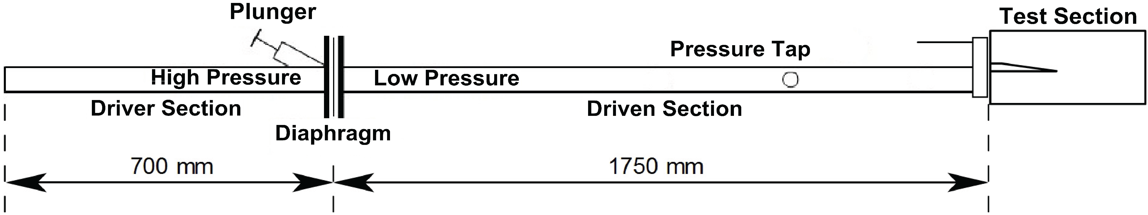
2.1. Shock Tube and Test Section Models
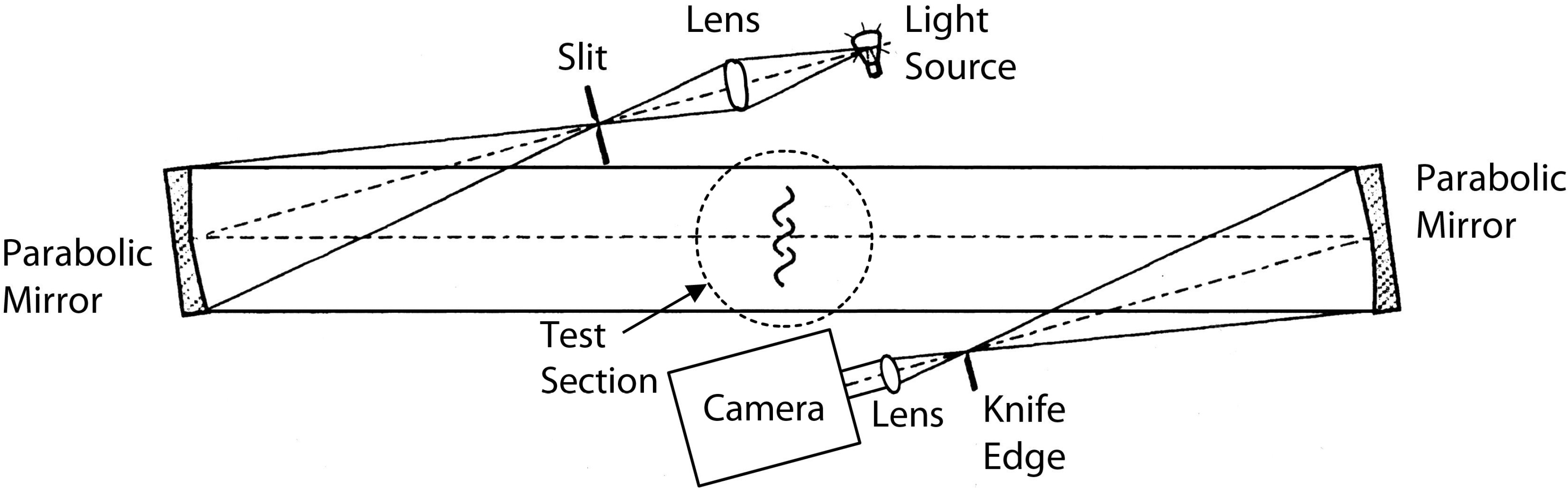
Referring to Figure 3, a shock tube of square cross-sectional area with side wall lengths of 24.8 mm and wall thickness of 2.6 mm was used, identical to the one that Gongora-Orozco et al. [26] used. The driver and driven sections were 700 mm and 1750 mm long respectively, both filled with air. The gas in the driven section was at ambient conditions. The pressure in the driver section was monitored using a Kulite XTL-190 transducer (Kulite Semiconductor Products Inc., Leonia, NJ, USA).
Figure 3. Schematic of the shock tube.
Aerospace 02 00001 g003
The two sections were initially separated by an acetate film of 19 and 75 μm to sustain the pressure ratio that generates an incident shock Mach number of 1.31 and 1.59 respectively [27]. The diaphragm was ruptured with a spring-loaded plunger pointing to the middle of it, which leads to the formation of a planar shock wave normal to the walls. The experimental error associated to the rig in the determination of the incident Mach number is between 1.08% and 3.4% for Mach in the range between 1.34 and 1.66 [28]. The shock wave travels along the tube finally reaching the test section where it diffracts at the corner.
The details of two test models used are illustrated in Figure 4. The choice of the geometry was motivated by the interest in observing the effect of the presence of slits in the diffraction process. The splitters are of the same length of 103.26 mm and thickness of 5.63 mm, with a slope of 8° on a horizontal length of 40 mm starting from model tip. On the tip, a spike pattern of 2.48 mm distance is generated. The dimensions have been chosen to have a sufficient amount of slots in order to make the model three-dimensional and minimise the sidewall effects. Additionally, the two models differ in the way that one has the spikes length twice as much of the other.
Figure 4. Geometry of the test models; (a) Side view; (b) Short spikes; (c) Long spikes.
Aerospace 02 00001 g004

2.2. Schlieren

A schlieren system was used in a typical Z-type configuration and schematically illustrated in Figure 5. The light beam is obtained from a 450 W continuous Xenon arc lamp and passes through a condenser lens with a 79 mm focal length and a slit before being collimated with a parabolic mirror of 203.3 mm diameter and 1016 mm focal length. The light beam then illuminates the test section and is focused by another parabolic mirror, a knife-edge and a focusing lens of 49 mm diameter, and captured by a recording unit. A Photron SA1.1 high-speed camera with a 12-bit dynamic range recorded data with a frame rate of 16,800 fps and exposure time of 1 μs.
The acquired photographs were then processed with ImageJ (NIH, Bethesda, MA, USA), subtracting a reference image corresponding to the wind-off condition (no flow) from the sequence of wind-on images in order to minimise non-uniform illumination and imperfections on the test section windows.
Figure 5. Schematic of the schlieren setup.
Aerospace 02 00001 g005

3. Results and Discussion

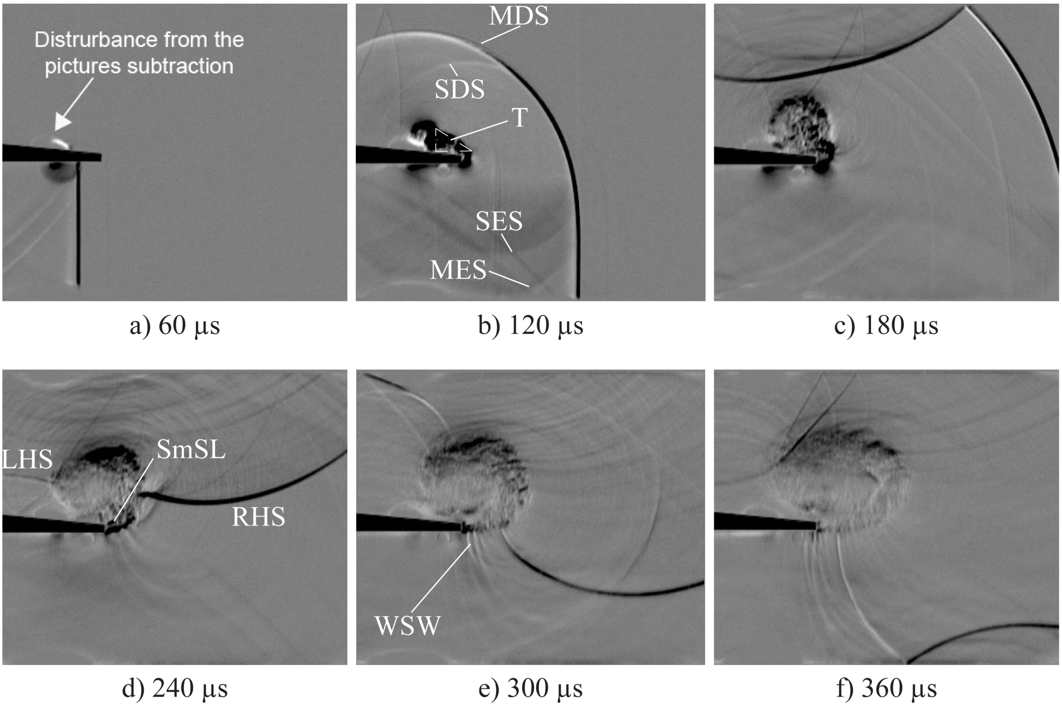
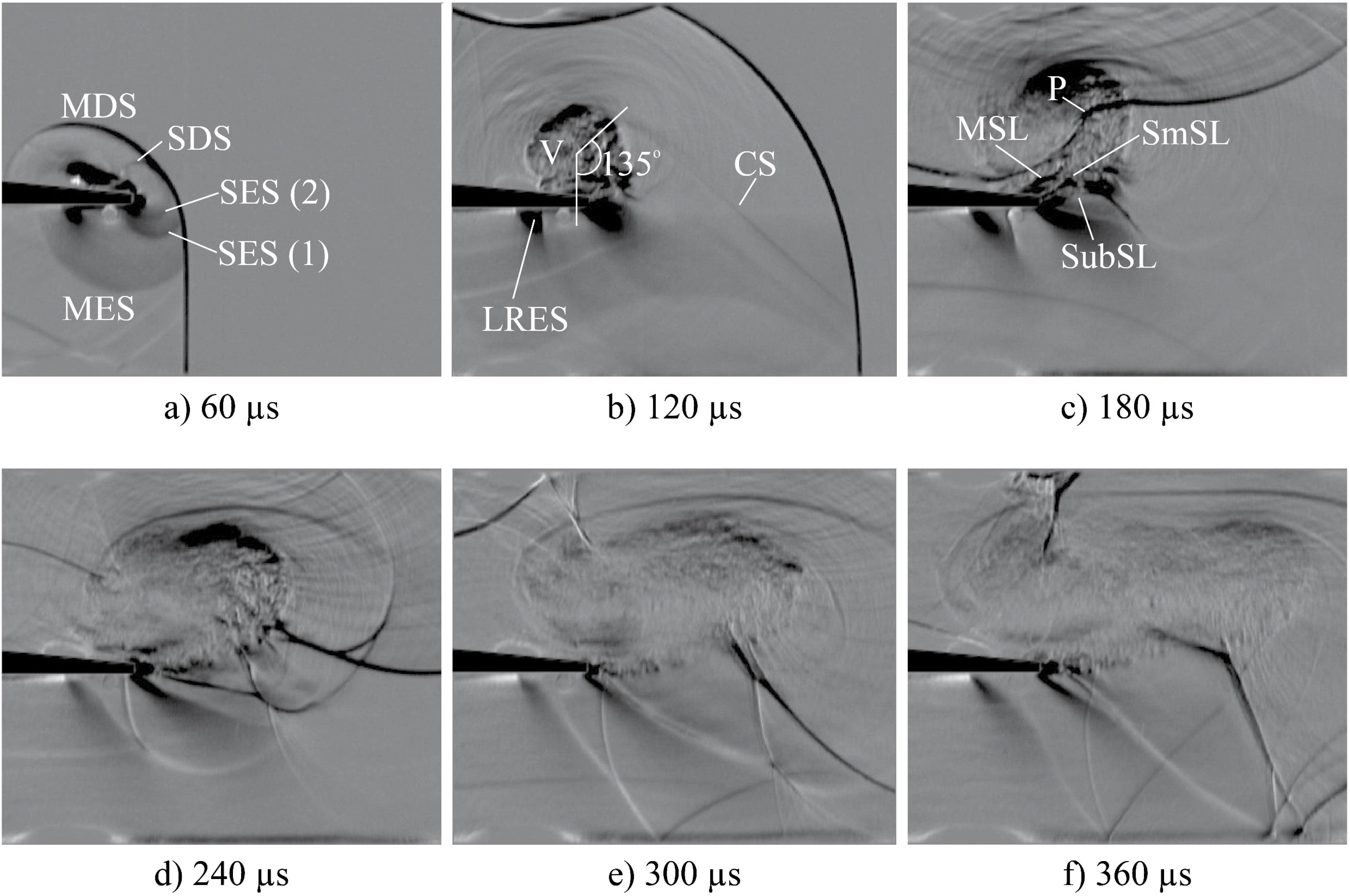
3.1. Mach Number of 1.31

Figure 6 and Figure 7 show the schlieren images corresponding to the diffraction pattern around the short- and long-spike splitters respectively. For each set, the reference time t 0 = 0 is taken as the image before the shock wave diffracts at the corner.
Figure 6. Schlieren sequence of diffraction around a short-spike wedge geometry with M = 1 . 31 .
Aerospace 02 00001 g006
Figure 7. Schlieren sequence of diffraction around a long-spike wedge geometry with M = 1 . 31 .
Aerospace 02 00001 g007
As Figure 8a–c schematically illustrates, the main two-dimensional diffraction process starts when the flow expands in the internal part of the spikes, diffracting around a 90° corner and referred as first diffraction (1). In reality, since in the internal part of the spikes the wall perpendicular to the lower surface is of finite length, the second diffraction (2) develops at a 82° corner according to Skews [13] about multi-facetted walls. In the initial stages the two shock wave diffractions occur separately with the development of a vortex at each corner, but as the vortices expand, they will merge into a more complicated shape, which shows some similarities with that of a plane shock wave interacting with slitted wedges [29,30]. The result of this interaction visibly produces in Figure 6b a unique diffracted shock, M D S , and reflected expansion wave, M E S , which belong to the main two-dimensional diffraction process that develops the main shear layer.
All the elements characterising the shock diffraction induce to think that the turbulent cloud, which forms on the upper side of the wedge and visible in Figure 6c and Figure 7c, has a vortical structure. This appeared to be confirmed by the slight distortion shown by the main diffracted shock wave ( M D S ) while travelling toward the turbulent cloud after being reflected on the upper side of the test section with a regular reflection, in analogy with the behaviour of the shock–vortex interaction [31,32,33,34]. The existence of the main slipstream rolling up into a turbulent cloud with a vortical arrangement is supported also by both the experimental and numerical findings by Mahomed and Skews [35] in which the formation of a vortex inside a turbulent separation bubble bounded by a shear layer was clearly visualised in Mach number vector plots.
Figure 8. Schematic of the shock wave diffractions around a short-spike wedge at M = 1 . 31 ; (a) Plane where the main shock wave diffraction occurs; (b) Initial stage; (c) Later stage.
Aerospace 02 00001 g008
As the flow passes along the spikes, since the pressure under the test model is higher than that of the undisturbed condition above it, the flow expands along the spike edges, giving rise to vortical structures. A planar representation is schematically shown in Figure 9a,b. The dimension of the vortices grows along the spikes in the axial direction and from the interaction of the vortices V 1 and V 2 in each slot a triangular shape, T, forms on the upper surface of the test model. This flow feature, starting from the main vortex to the corner extremity, is illustrated in Figure 6b and more evidently in the long-spike geometry in Figure 7b, since the incoming flow navigates over a longer distance along the spikes. The complicated structure, schematically shown in Figure 10, is due to the fact that, as soon as the vortices illustrated in Figure 9b interact with each other, they lose their shape and generate a turbulent formation that grows in size as time passes.
Figure 9. Schematic of the shock wave diffractions around a short-spike wedge and M = 1 . 31 ; (a) Plane where the shock wave diffraction along the spanwise direction occurs; (b) Details.
Aerospace 02 00001 g009
In analogy to that described above, when the flow arrives at the wedge extremity, a weaker two-dimensional diffraction occurs at the 90° corner labelled subordinate shock wave diffraction, which produces the subordinate shear layer, reflected sound wave and diffracted shock wave in Figure 10. Another diffraction process takes place at 82°; even though it does not produce a detectable effect in Figure 6b, it becomes evident in Figure 6d, where the small shear layer, S m S L , is perceivable on the upper corner of the spikes tip. The presence of large gradients in density and the small resolution of the schlieren images in the first stages of Figure 6 are believed to be the reason of the appearance of only one subordinate diffracted shock, S D S , and expansion wave, S E S , in the short-spike image sequence. In the long-spike case instead the two diffractions at the corner tip are clearly visible in Figure 7b as the expansion waves, S E S ( 1 ) and S E S ( 2 ) , can be detected. In both geometries the subordinate diffracted shock tends to fade away while approaching the upper surface of the model, yet appears to enforce the main diffracted shock in the part where they combine into a single wave.
Figure 10. Schematic of all the diffraction processes around a short-spike wedge at M = 1 . 31 .
Aerospace 02 00001 g010
The main diffracted shock, after having reflected from the upper wall of the test section, travels back toward the vortex core. The shock–vortex interaction occurring in Figure 6d and Figure 7d exhibits a disrupting nature, after which the turbulent region steadily loses its configuration while it expands moving in the downstream direction. The different length of the spikes produces a perceivable effect in the comparison of Figure 6d with Figure 7d. The long-spike geometry produces a larger turbulent vortex that lies on a wider area on the upper wall of the model and the shock–vortex interaction seems to be more effective in the breakage of the vortical shape, as shown in Figure 6f and Figure 7f. This is due to the fact that in the long-spike case, the incoming flow arriving from the channel under wedge expands over a longer distance with a consequent wider corridor between the main and small slipstreams and the effect of making the turbulent cloud less compact, in Figure 7e.
The shear layer enables the passage of the shock through it, leading to the generation, in Figure 6d, of the left-hand wave, L H S , which opposes the vortex rotation and symmetrically travels around the vortex as opposed to the shock on the right-hand side, R H S . In Figure 6e a number of weak sound waves, W S W , form on the initial part of the shear layer in the short-spike corner, confirming that, as suggested by Skews et al. [2], this wave pattern appears in the presence of a three-dimensional perturbation.
Figure 7e exhibits an interesting phenomenon. The main diffracted shock impinges the splitter surface where it is broken, and the wave on the right-hand side of the vortex, visible in the lower part of the test section, can be divided in two parts. The wave R H S 1 is the right-hand shock that has reflected from the upper wall of the test section and travels downwards whereas the wave R H S 2 has passed through the slots. After the passage through the slots, the wave R H S 2 expands along the spanwise direction, similarly to the other waves previously described losing its strength and forming some weak waves that join the R H S 1 in an irregular way. This proves that the interaction between the vortex and the reflected diffracted wave does not completely break the shock at the spike tip but passes through the slots and breaks when reaching the internal part of the spikes.

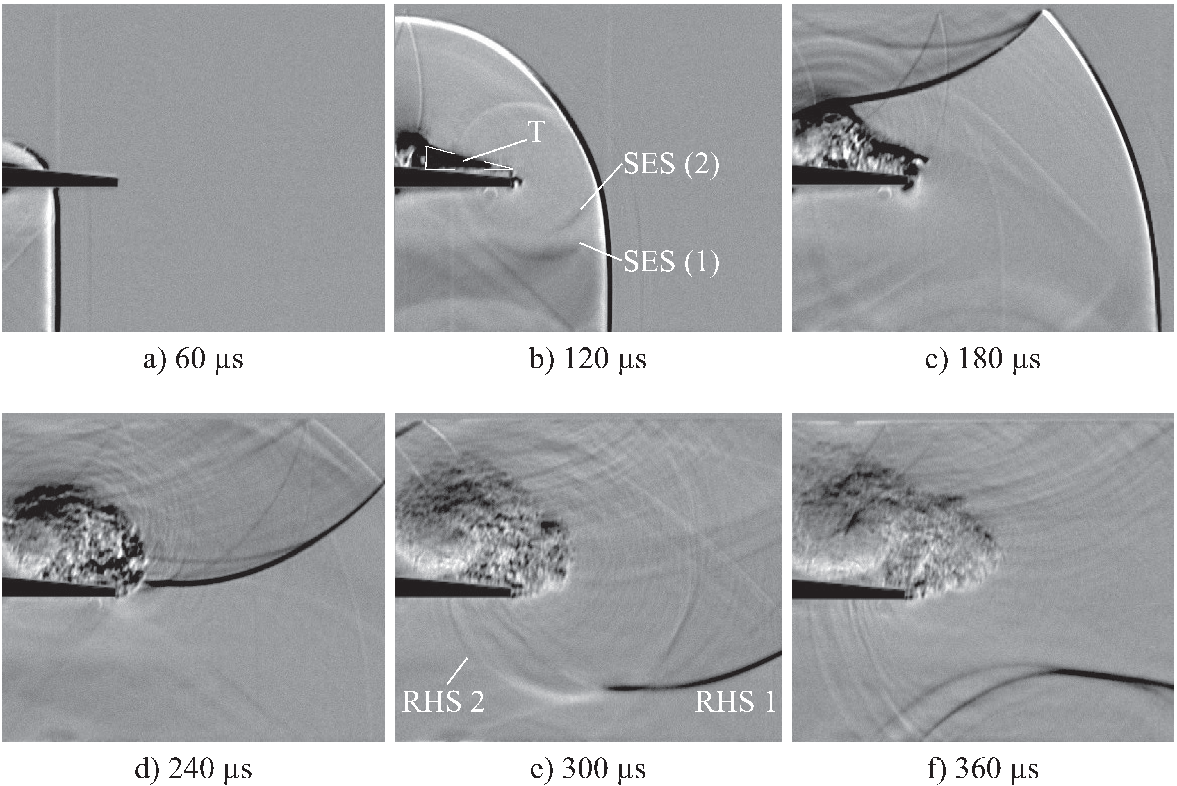
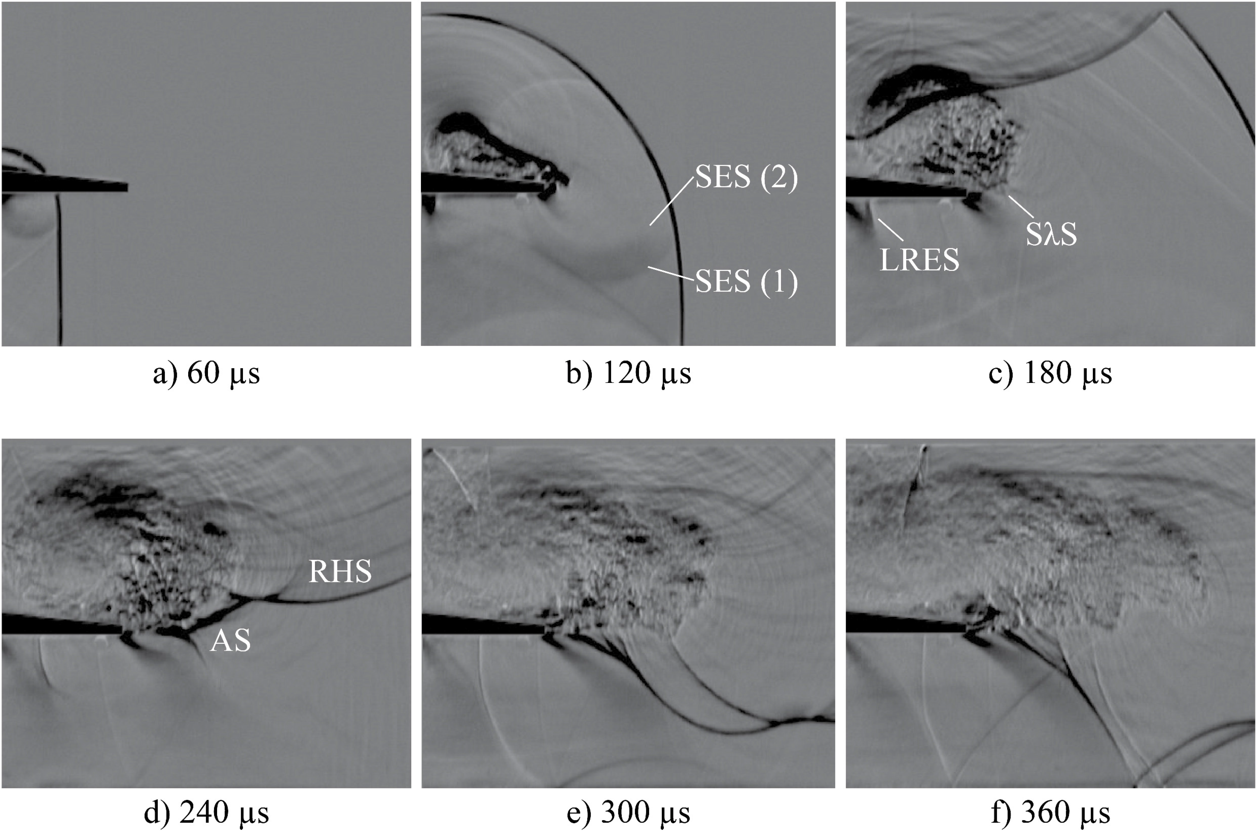
3.2. Mach Number of 1.59

The flow evolution illustrated in Figure 11 and Figure 12 presents similar characteristics highlighted for the lower Mach number case in Section 3.1. The greater strength of the incoming flow generates stronger flow structures, which evolve at a higher rate and propagate downstream faster. In this case the expansion wave S E S ( 2 ) of the subordinate shock diffraction at the 82° corner can be clearly discerned in both geometries in Figure 11a and Figure 12b.
Figure 11. Schlieren sequence of diffraction around a short-spike wedge geometry with M = 1 . 59 .
Aerospace 02 00001 g011
Figure 12. Schlieren sequence of diffraction around a long-spike wedge geometry with M = 1 . 59 .
Aerospace 02 00001 g012
Figure 11a depicts that the main diffracted shock fades near the wall. Since the incident shock front has just passed the tip, the subordinate shock diffraction is in its early stages and merges with the main diffracted shock. hlThe contact surface of the main shock diffraction, C S , appears as a very weak wave because it is discontinuously present along the spanwise direction, but can be identified in Figure 11b for the short-spike case only. It starts from the main diffracted shock wave but it is not clear where it terminates, as it reaches the main slipstream at approximately 135° around the vortex where the patch of turbulence covers it.
Figure 11b and Figure 12c illustrate that, while the main and subordinate expansion waves travel upstream, they slightly affect the Prandtl–Meyer fan at the first 90° corner, making the last running expansion shock wave, L R E S , to rotate toward the upstream direction.
In Figure 11c a new flow feature appears on the subordinate shear layer. The flow that arrives at the spikes extremity travels at a higher speed than that in the case of Mach number of 1.31. It abruptly separates from the surface and expands navigating on the subordinate slipstream, S u b S L , where it is accelerated to a local Mach number sufficiently high to generate a lambda shock that is required to match the pressure conditions behind the incident wave. The lambda shock generates a bit further from of the corner tip, at the location of the nook on the subordinate shear layer. The complicated structure, schematically shown in Figure 13, is due to the perturbation induced by the slots since a certain amount of incoming flow passes across these apertures where it is accelerated by the expansion fan occurring at 90° corner, and travels in the corridor bounded by the vortex and the subordinate shear layer. The presence of the small slipstream, S m S L , which appears to stop at a certain distance from the wall, produces a convergent-divergent nozzle in the area between the main, M S L , and the small slipstreams. In the case of the longer spikes, the inception of a small lambda shocklet structure, S λ S , seems to be present on the subordinate slipstream near the splitter tip in Figure 12c but the passage of the returning main diffracted shock deeply influences the flow evolution.
Figure 13. Schematic of all diffraction processes around a short-spike wedge at M = 1 . 59 .
Aerospace 02 00001 g013
The interaction of the vortex with the returning main diffracted shock accelerates the transition of any flow structure to a large patch of turbulence, as illustrated in Figure 11c and Figure 12c. The rotation of the vortex gives rise to a velocity variation able to strongly deform the transmitted wave in Figure 11c. The point P where the rupture will probably happen is visible and the width of the corridor generated between the main and the subordinate shear layers can be determined.
When the left-hand shock reflects from the upper surface of the test model, part of the transmitted wave passes across the spikes, reducing the strength of expansion fan at the 90° corner in correspondence of the internal part of the splitter, as Figure 11d and Figure 12d show. This gives rise to an induced shock wave that, as soon as it interacts with the incoming flow, quickly loses its strength and, in the case of the short spikes, in Figure 11d, joins the acoustic waves that in the meantime have formed on the lambda shock tail. As Figure 12d depicts, in the long-spike geometry, the remaining part of the wave, labelled arc of shock, A S , is not affected by the presence of the splitter and intersects with the portion of shock that has travelled on the right-hand side of the turbulent vortex, R H S . The shock A S also is detached from the model tip where instead an expansion fan is present, meaning that the subordinate shear layer exhibits a change in curvature in that point. Moreover, while travelling upstream, the wave AS changes its pattern to a Mach reflection with three branches in Figure 12e.

4. Conclusions

A qualitative investigation has been made on the shock diffraction over a wedge with longitudinal slits providing a description of the main flow features. The flow pattern analysed would provide material for a meaningful comparison and validation of numerical codes. A combination of sequential shock wave diffractions is created while the flow navigates along the spikes. The various processes take place in different planes generating a complex flow pattern, characterised by a turbulent cloud with a vortical structure located in the upper channel of the test section, in agreement with related studies.
The two-dimensional shock diffractions develop in the axial planes spaced out along the spanwise direction due to the presence of the spikes. In the internal part of the spikes, the main diffraction is situated on layers covered by the test model and therefore the detection of flow structures was quite challenging. The shock wave diffraction in proximity of the spike extremities was clearly identified since two of the levels on which this phenomenon occurs are placed in correspondence of the test section windows. This process appeared stronger as the Mach number increases and weaker in the long-spike splitter.
The shock–vortex interaction causes the shock to be entirely transmitted without being broken while passing through the vortex, even though a higher incoming Mach number produces a greater distortion. The shock wave splits into two waves only when it impinges on the test model surface, and the part that passes inside the patch of turbulence partially crosses the spikes. In the long-spike case, a complicated flow structure was detected on the right-hand side of the turbulent vortex, and its generation requires further investigations.
Overall the spike seems to have a dampening effect on the unsteadiness of the shock wave diffracting at corner independently of the length of the slots. However, the schlieren technique is an integral approach along the spanwise direction, and therefore the flow details in the spanwise direction are overlapped and difficult to quantify. Three-dimensional analysis is a topic for further research using other shapes and sizes of the tip and internal part of spikes. Investigation of the flow pattern in selectable planes is recommended, fulfilling the possibility to detect the flow development in different levels.

Acknowledgments

The authors are indebted to the EPSRC Engineering Instrument Pool, especially Mr. Adrian Walker for the loan of the high-speed camera.

Author Contributions

Francesca Gnani: Experimental campaign and data analysis; Kin Hing Lo: Experimental campaign; Hossein Zare-Behtash: Experimental campaign and project supervisor; Konstantinos Kontis: Project supervisor.

Nomenclature

AS
Arc of shock
CS
Contact surface
LHS
Left-hand side shock wave
LRES
Last running expansion shock wave
MDS
Main diffracted shock wave
MES
Main expansion shock wave
MSL
Main shear layer
RHS
Right-hand side shock wave
SDS
Subordinate diffracted shock wave
SES
Subordinate diffracted expansion shock wave
SmSL
Small shear layer
SubSL
Subordinate shear layer
SλS
Lambda shocklet structure
T
Triangular shape
V
Vortex
WSW
Weak sound waves

Conflicts of Interest

The authors declare no conflict of interest.

References

  1. Skews, B.W. The perturbed region behind a diffracting shock wave. J. Fluid Mech. 1967, 29, 705–719. [Google Scholar] [CrossRef]
  2. Skews, B.W.; Law, C.; Muritala, A.; Bode, S. Shear layer behavior resulting from shock wave diffraction. Exp. Fluids 2012, 52, 417–424. [Google Scholar] [CrossRef]
  3. Bazhenova, T.V.; Gvozdeva, L.G.; Nettleton, M.A. Unsteady interactions of shock waves. Prog. Aerosp. Sci. 1984, 21, 249–331. [Google Scholar] [CrossRef]
  4. Abate, G.; Shyy, W. Dynamic structure of confined shocks undergoing sudden expansion. Prog. Aerosp. Sci. 2002, 38, 23–42. [Google Scholar]
  5. Lighthill, M.J. The diffraction of blast I. Proc. R. Soc. Lond. A 1949, 198, 454–470. [Google Scholar] [CrossRef]
  6. Skews, B.W. The shape of a diffracting shock wave. J. Fluid Mech. 1967, 29, 297–304. [Google Scholar] [CrossRef]
  7. Henderson, L.F. Regions and boundaries for diffracting shock wave systems. Z. Angew. Math. Mech. 1987, 67, 73–86. [Google Scholar] [CrossRef]
  8. Bazhenova, T.V.; Gvozdeva, L.G.; Zhilin, Y.V. Change in the shape of the diffracting shock wave at a convex corner. Acta Astronaut. 1977, 6, 401–412. [Google Scholar] [CrossRef]
  9. Srivastava, R.S. On the vorticity distribution over a normal diffracted shock for small and large bends. Shock Waves 2012, 23, 525–528. [Google Scholar] [CrossRef]
  10. Whitham, G.B. New approach to problems of shock dynamics, Part II: Three-dimensional problems. J. Fluid Mech. 1959, 5, 369–386. [Google Scholar] [CrossRef]
  11. Jones, D.S.; Whitham, G.B. An approximate treatment of high-frequency scattering. Proc. Camb. Philos. Soc. 1957, 53, 691–701. [Google Scholar] [CrossRef]
  12. Li, H.; Ben-Dor, G.; Han, Z.Y. Analytical prediction of the reflected-diffracted shock wave shape in the interaction of a regular reflection with an expansive corner. Fluid Dyn. Res. 1994, 14, 229–239. [Google Scholar] [CrossRef]
  13. Skews, B.W. Shock wave diffraction on multi-facetted and curved walls. Shock Waves 2005, 14, 137–146. [Google Scholar] [CrossRef]
  14. Quinn, M.K. Shock Diffraction Phenomena and Their Measurement. Ph.D. Thesis, University of Manchester, Manchester, UK, 2013. [Google Scholar]
  15. Sun, M.; Takayama, K. Vorticity production in shock diffraction. J. Fluid Mech. 2003, 478, 237–256. [Google Scholar] [CrossRef]
  16. Quinn, M.K.; Kontis, K. A combined study on shock diffraction. In Proceedings of the 5th Symposium on Integrating CFD and Experiments in Aerodynamics, Tokyo, Japan, 3–5 October 2012.
  17. Quinn, M.K.; Kontis, K. Experiments and simulations of weak shock wave diffraction phenomena. In Proceedings of the 20th International Shock Interaction Symposium, Stockholm, Sweden, 20–24 August 2012.
  18. Reeves, J.O.; Skews, B.W. Unsteady three-dimensional compressible vortex flows generated during shock wave diffraction. Shock Waves 2012, 22, 161–172. [Google Scholar] [CrossRef]
  19. Sun, M.; Takayama, K. A note on numerical simulation of vortical structures in shock diffraction. Shock Waves 2003, 13, 25–32. [Google Scholar] [CrossRef]
  20. Sun, M.; Takayama, K. The formation of a secondary sock wave behind a shock wave diffracting at a convex corner. Shock Waves 1997, 7, 287–295. [Google Scholar] [CrossRef]
  21. Bazhenova, T.V.; Bulat, O.V.; Golub, V.V.; Shul’meister, A.M. Three-dimensional diffraction of a shock wave. Fluid Dyn. 1993, 28, 153–154. [Google Scholar] [CrossRef]
  22. Zare-Behtash, H.; Gongora Orozco, N.; Kontis, K. Effect of primary jet geometry on ejector performance: A cold-flow investigation. Int. J. Heat Fluid Flow 2011, 32, 596–607. [Google Scholar] [CrossRef]
  23. Zare-Behtash, H.; Kontis, K.; Gongora Orozco, N.; Takayama, K. Shock wave-induced vortex loops emanating from nozzles with singular corners. Exp. Fluids 2010, 49, 1005–1019. [Google Scholar] [CrossRef]
  24. Barbosa, F.J.; Skews, B.W. Shock wave interaction with a spiral vortex. Phys. Fluids 2001, 13, 3049–3060. [Google Scholar] [CrossRef]
  25. Ferri, A. Review of scramjet propulsion technology. J. Aircr. 1968, 5, 3–10. [Google Scholar] [CrossRef]
  26. Gongora-Orozco, N.; Zare-Behtash, H.; Kontis, K. Global unsteady pressure-sensitive paint measurements of a moving shock wave using thin-layer chromatography. Measurement 2010, 43, 152–155. [Google Scholar] [CrossRef]
  27. Zare-Behtash, H.; Kontis, K.; Gongora Orozco, N.; Takayama, K. Compressible vortex loops: Effect of nozzle geometry. Int. J. Heat Fluid Flow 2009, 30, 561–576. [Google Scholar] [CrossRef]
  28. Gongora-Orozco, N. Experimental Studies on Internal Shock Wave Phenomena and Interactions. Ph.D. Thesis, University of Manchester, Manchester, UK, 2010. [Google Scholar]
  29. Onodera, H.; Takayama, K. Interaction of a plane shock wave with slitted wedges. Exp. Fluids 1990, 10, 109–115. [Google Scholar] [CrossRef]
  30. Skews, B. Shock wave interaction with porous plates. Exp. Fluids 2005, 39, 875–884. [Google Scholar] [CrossRef]
  31. Ellzey, J.L.; Henneke, M.R.; Picone, J.M.; Oran, E.S. The interaction of a shock with a vortex: Shock distortion and the production of acoustic waves. Phys. Fluids 1995, 7, 172–184. [Google Scholar] [CrossRef]
  32. Dosanjh, D.S.; Weeks, T.M. Interaction of a starting vortex as well as a vortex street with a traveling shock wave. AIAA J. 1965, 3, 216–223. [Google Scholar] [CrossRef]
  33. Chang, S.M.; Chang, K.S.; Lee, S. Reflection and penetration of a shock wave interacting with a starting vortex. Phys. Fluids 2004, 42, 796–805. [Google Scholar] [CrossRef]
  34. Chang, K.S.; Chang, S.M. Scattering of shock into acoustic waves in shock-vortex interaction. Mater. Sci. Forum 2004, 465–466, 131–138. [Google Scholar] [CrossRef]
  35. Mahomed, I.; Skews, B.W. Diffraction of an expansion wave around a 90°. In Proceedings of the 29th International Symposium on Shock Waves, Madison, GA, USA, 14–19 July 2013.

