Abstract
Modern high-bypass turbofan engines often operate near their structural natural frequencies, posing significant challenges for vibration isolation in aircraft engine mount systems. This study presents a comprehensive modal optimization framework to enhance vibration isolation performance by maximizing the separation between excitation and natural frequencies. A dynamic model of a typical single-aisle airliner engine mount system is formulated. Modal analysis is conducted via finite element modeling in Abaqus, extracting 20 modes and identifying dominant modes based on effective mass criteria. To avoid resonance within the excitation range of 72–336 Hz, a genetic algorithm is employed in MATLAB R2023a (9.14) to optimize key geometric parameters, including mount thicknesses and thrust link dimensions. The optimized configuration achieves a 16.84% increase in minimum frequency separation and a 21.51% reduction in vibration transmissibility. The results demonstrate the efficacy of combining modal analysis with evolutionary algorithms in designing advanced engine mounting systems for improved vibration isolation in next-generation aircraft.
1. Introduction
The Efficient vibration isolation performance of the engine mounts is key in enhancing the overall performance of an aircraft. The aircraft engine mounts absorb and dampen vibrations resulting from the engine’s operation, preventing the transmission of those vibrations to the airframe and other aircraft components [1]. If left unchecked, vibrations can be detrimental to the maneuverability, comfort, stability, and overall efficiency of the aircraft by causing increased fatigue and wear and tear on aircraft structures and avionics instruments [2,3].
In addition to designing aircraft engine mounts to isolate vibrations, these structures must also securely connect the engine to the airframe, transmit static loads from the engine, and transfer engine thrust [4]. Thus, design optimization is beneficial in ensuring optimal vibration suppression while maintaining the required weight, strength, and stiffness for overall efficiency [5].
Currently, turbofan engines that power airliners typically operate at frequencies close to their natural frequencies. This scenario arises from modern turbofan engines having large diameters, relatively low speeds, high bypass ratios, and generating high thrust [6,7]. Research has also shown that high bypass ratios may result in gradual decreases in fan rotor speeds [8,9]. The reduction in working speed pushes the working frequencies to the middle and lower frequency bands, thereby transmitting low- and medium-frequency vibrations to the airframe. Given these contemporary realities, designs of engine mount systems aimed at optimal vibration isolation must emphasize an approach where dominant frequency modes are well separated from the natural frequencies to reduce force transmissibility into the fuselage. To attain this design objective, contemporary analyses blend high-fidelity finite element modal characterization with optimization to modify the mount system’s parameters.
Modal analysis remains at the core of identifying critical modes and potential resonances with numerous recent studies applying comprehensive modal identification strategies suitable for complex structures like aircraft engine mount systems. For instance, the approach of using modal analysis results as a basis for optimizing vibration isolation performance is emphasized by a recent study commissioned by the Yantai Automobile Engineering Professional College [10]. The study aimed to obtain the vibration response characteristics of the engine mount system using FEM and concluded that the accuracy of the simulation results is high, with peak deviation from the experimental value and the natural frequency being less than 5%. Similarly, Mazzeo et al. [11] proposed a modal identification approach that scales large models, which is very useful when screening several design variables in an optimization loop.
Domain-specific evidence for turbofan aircraft engines demonstrates the pros and cons of emphasizing frequency separation and modal decoupling as a strategy for reducing vibration transmissibility. A recent study by Jianqiang et al., [12] adopted an optimization strategy based on modal design parameters with the aim of modifying the distance between the natural frequencies of the mount system and the engine’s excitation frequency. The study’s findings demonstrated a significant increase in the system’s vibration isolation range and an overall decrease in vibration transfer, thus greatly improving the engine mount’s performance. A parallel study [13] investigating vibration optimization design techniques for link mounts in turbofan engines employed an optimization strategy anchored on modal design ideas, with results showing reductions of up to 54.8% in the system’s vibration transfer rate. Another study [14] based on a full-scale turbofan using multibody dynamics formulation highlighted the importance of taking into account joint compliance and mount nonlinearity. The findings underscored the importance of accurate low-frequency modeling of mount systems in predicting vibration isolation efficacy. Overall, these studies illustrate the importance of separating natural frequencies and excitation orders in aircraft engine mount systems.
On the other hand, genetic algorithms (GAs) have gained prominence in mount design optimization given the efficiency in handling multi-modal objectives such as mass, transmissibility and constraints. Qin et al. [15] used GA to optimize hydraulic engine mounts, thus reducing evaluation costs and simplifying a highly dimensional design functionality. This approach is relevant to the design optimization of aircraft engine mounts, where the evaluation of many modal variants is necessary. Practically, an Abaqus-based analysis enables systemic identification of dominant modes while the subsequent GA optimization modifies discrete and continuous variables.
Whereas GA remains a popular tool in engineering optimization, there are newer techniques in evolutionary computation that seek to address the shortcomings of traditional GA. One such technique enhances the Success-History based Adaptive Differential Evolution (SHADE) with the Linear Population Size Reduction (LPSR) and is known as the L-SHADE algorithm [16]. The technique, known for superior performance on continuous optimization problems, improves both exploration and exploitation capabilities. L-SHADE optimization is thus applied to compare the GA optimization results.
Therefore, it is crucial to apply a modal optimization technique based on genetic algorithms to maximize the distance between the natural frequencies of the mounting system and the excitation frequencies, thereby achieving optimal vibration isolation performance. This paper presents the modal analysis of a typical engine mount system of a modern airliner. It builds on the modal characteristics to optimize specific design parameters and the frequency separation distance.
The novelty of this work lies in its combination of a high-fidelity modal characterization with an optimization framework that is specifically designed for modern large-diameter turbofan engine mount systems. In contrast to previous studies that mainly focus on isolated modal assessment or basic parametric tuning, this research utilizes effective mass criteria to identify dominant modes and integrates them into a frequency-separation driven optimization framework. This approach offers a more thorough and structurally sound way to improve the vibration isolation performance of next-generation turbofan engine mount systems.
The paper has four other core sections apart from the introduction, covered in Section 1. Section 2 outlines the methods that the study employs to achieve the results. To ensure a better understanding of the methodology, Section 2 is subdivided into four subsections. Section 2.1 explains the dynamic modeling and optimization of the engine mount system, where the engine is modeled as a rigid body, and the relevant equations are derived. Section 2.2 explains the finite element modeling approach on Abaqus. In Section 2.3, the modal analysis is outlined in detail. Section 2 closes with Section 2.4, which outlines the optimization analysis on MATLAB based on the results of the modal analysis. Section 3 presents the results of the study and is divided into three subsections. In Section 3.1, the results of the modal analysis are outlined, while Section 3.2 presents the results of the optimization analysis. Section 3.3 is the last in Section 3 and contains validation of the results. Section 4 discusses the results of the study, while Section 5 contains the conclusion, which summarizes the study.
2. Methods
The aircraft engine mount system analyzed in this paper is that of a typical modern single-aisle airliner, comprising a forward mount that rests on the fan, a rear mount located on the turbine frame, and thrust links. Additionally, the paper simplifies the engine into a dummy engine for ease of analysis.
In the mount system’s configuration for this paper, the engine’s vertical and side loads are distributed between the forward and aft mounts. On the other hand, the axial loads are transmitted through the thrust links to the aft mount. The vertical force couple between the forward and aft mounts transfers the engine’s pitch moment, while the side force couple between the aft and forward mounts transfers the engine’s yaw moment. Additionally, the rear mount handles the engine roll moment.
2.1. Dynamic Modeling and Optimization of the Engine Mount System
The engine is modeled as a rigid body with mass m and inertia tensor J, subject to thrust T. The modeling begins with equations of motion derived from Lagrange’s equations of motion.
where q represents the general displacement vector in 6-DOF, M is the mass matrix is the external force vector, K is the stiffness matrix, is the thrust vector position relative to the center of gravity (CG), T is the axial thrust and C is the damping matrix. The study employs viscous damping, with a damping ratio of 5% (0.05).
Assuming a typical 3-point turbofan mount system, the stiffness matrix is formulated as follows:
where Ti is the transformation matrix and accounts for the mount’s orientations.
Formulating the total potential energy, V takes into account the thermal deformation effects resulting in the following:
where represents the thermal expansion coefficients.
From the undamped free vibration results, the following characteristic equation can be obtained for the engine mount system:
where is the thrust-induced stiffness, represents the natural frequencies and represents the mode shapes.
Solving the characteristic equation results in the following:
where p represents the design parameters such as length and thickness.
For the frequency response considerations, the transfer function takes into account the rotation effects in the assembly, resulting in the following:
where is the frequency response function, and G represents the gyroscopic matrix. with as the polar moment of inertia and as rotational speed.
Critical modes are identified when peaks within the excitation range of rad/s.
Modeling the optimization variables begins with defining the design variables.
Let
where is the forward mount thickness; is the aft mount thickness; L is the thrust link length; and W is the thrust link width.
The objective function’s modeling is to maximize the frequency margin between the system’s natural frequency and the excitation frequency as follows:
The following constraints apply to this study:
Stress Constraints/Von Mises stress ():
Displacement Constraints:
Mass Constraint:
Fan blade clearance constraint:
where x is the design variable vector and is the fan blade tip clearance.
2.2. Finite Element Modeling on Abaqus
The study involves creating a finite element model of the engine mount system on Abaqus CAE. The material selection for this research is informed by the 12th edition Metallic Materials Properties Development and Standardization Handbook (MMPDS-12) [17]. Based on these standards, the front mount is made of Ti-6Al-4V, while the aft mount is made of Inconel 718. Ti-6Al-4V is desirable for its excellent corrosion resistance and high specific strength. Inconel 718 offers excellent mechanical properties and high-temperature strength. The material 15-5PH is used for the thrust links, and cast iron is used for the dummy engine. The martensitic steel 15-5PH is ideal for its high strength, corrosion resistance, and good toughness, while cast iron (GJL-250) is chosen for its high compression strength and good machinability. Modern turbofan engine mount assemblies typically use precipitation-hardened stainless steel and titanium alloys. The study’s material selection thus represents the common classes used in industry today. However, recent aerospace materials trends have seen the emergence of alternatives such as titanium matrix composites and aluminum–lithium alloys. Table 1 below provides a summary of the material properties used for this research.

Table 1.
Material properties.
The study applies fully fixed (encastre) boundary conditions on all the nodes on the mounting interfaces of the pylon attachment lugs to model the pylon–wing interface. This means that the engine mount’s connection to the wing structure limits the translational and rotational degrees of freedom on the mating surfaces. This idealized constraint is only applied to the pylon attachment surfaces, not to the whole pylon or wing volumes, which are not modeled in this study. The fully fixed constraints are adopted because, in practical scenarios, the engine mount system is much stiffer than the wing–pylon assembly around it, and the area where the two parts are attached acts as a semi-rigid support for the frequencies of interest. The pylon and wing are simplified to fixed boundary conditions, with the engine simplified as a dummy, resulting in the model shown in Figure 1 below.
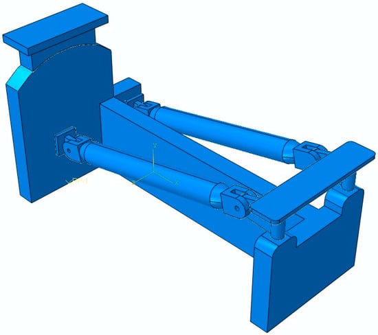
Figure 1.
FEM Model of the Engine Mount System.
2.3. Modal Analysis
This analysis is configured as a linear perturbation analysis using the Lanczos eigen solver. This study uses a frequency extraction range from 0 to 2000 Hz, with a minimum of 20 modes requested to ensure the capture of at least 90% of the Effective Mass in all directions. Since a modal analysis is linear, the research ignores the nonlinear effects in the model. Additionally, the connecting parts in the engine mount system are simplified to spring elements, whose translational stiffness and rotational stiffness are set to 1 × 10⁸ N/mm and 1 N/mm, respectively, in accordance with aviation best practices. The resulting 20 modes are analyzed to identify the dominant modes.
2.4. Optimization Analysis Based on the Modal Characteristics
The study incorporates an optimization process based on the modal characteristics of the engine mount system. This process aims to enhance the vibration isolation performance of the engine mount system by ensuring that its natural frequencies avoid the excitation frequency range. The optimization step may also modify the mechanical properties of the system, such as damping, stiffness, and Mass, as well as the geometric properties of the system, such as length and thickness, without compromising the strength requirements. This precautionary measure is crucial to keep the system’s natural frequencies away from the excitation frequency and ensure that the vibration transfer rate is large enough for optimal isolation efficiency. The variables for this optimization process are the 20 modes from the modal analysis step, the engine excitation range, and the initial design parameters of the engine mount system. In formulating the objective function, the study uses the entire modal spectrum of 20 modes.
Genetic algorithm (GA) optimization in MATLAB, which iteratively modifies key design specifications to maximize the separation between the system’s excitation frequencies and natural frequencies, serves as a baseline optimization method. GA optimization is used with a population size of 50, chromosome length of 7, crossover probability of 0.8, and a mutation probability automatically adjusted by MATLAB. The selected population size and adaptive mutation are to ensure diversity without excessive computation. MATLAB R2023a (9.14) initializes the generation of parent populations, which are then modified in a series of iterations to improve the population.
A candidate design vector for each individual is generated in the GA population, after which a Python 3.11 script automatically updates the corresponding Abaqus input file with the new geometric parameters. Abaqus is then executed in batch mode to perform a modal analysis, and the resulting .odb file is read back into MATLAB via the Abaqus Python application programming interface (API) to extract the updated natural frequencies used in the evaluation of the objective function. This automated loop continues for each generation until convergence.
L-SHADE optimization is implemented and compared with the GA optimization. The algorithm is configured with a maximum of 10,000 function evaluations, a memory size of H 10, and a p-best rate of 0.11 in line with best practices for engineering optimization problems. Figure 2 outlines the methodology.
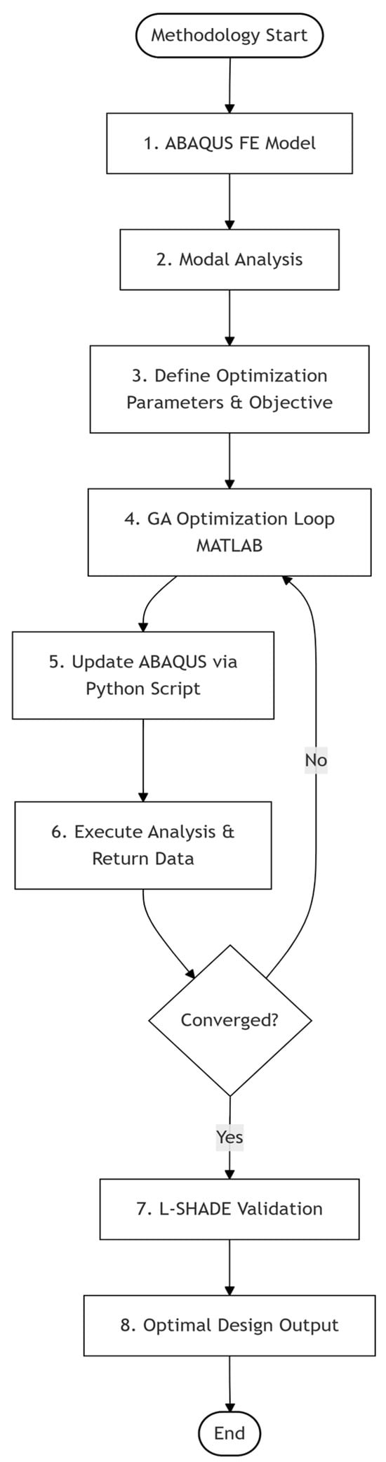
Figure 2.
Flowchart of the methodology.
3. Results
3.1. Modal Analysis Results
As outlined in the methodology, the modal step requests for 20 modes. Table 2 lists all 20 modes, along with their respective frequencies and effective mass fractions.
Table 2.
Frequency values and effective mass fraction values at every mode.
The characteristics of the 20 modes obtained from the modal step are analyzed to identify the dominant modes. Given the multi-component nature of engine mount systems, dominance cannot be inferred solely from frequency order. Thus, to identify dominant modes, the study identifies modes whose total effective mass in any direction accounts for a significant percentage of the total movable mass of the engine mount model. This ensures that the selected dominant modes are physically meaningful. The modes whose effective mass fractions in any direction exceed 1% are thus identified as dominant and are modes 1, 2, 3, 4, 5, 9, 10, 11, 13, 14, 15, 16, 17, and 18. Table 3 outlines all the dominant modes.
Table 3.
Dominant modes.
To ascertain the selection of sufficient modes, the total effective mass in each direction must be greater than 90% of the model’s Mass. From Table 3 above, the total effective mass fractions in the x, y, and z directions are 93.777%, 98.493%, and 99.813%, respectively, thus meeting the sufficiency criteria. Figure 3, Figure 4 and Figure 5 below show some of the dominant modes 3, 4, and 5, respectively.
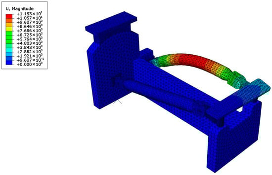
Figure 3.
Mode 3.
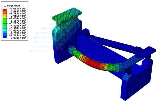
Figure 4.
Mode 4.
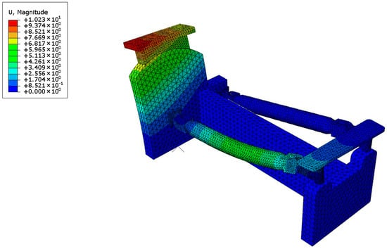
Figure 5.
Mode 5.
The engine mount system analyzed in the paper is assumed to be that of a large-diameter, high-bypass-ratio turbofan engine with relatively low fan speeds. Going by industry standards, the maximum fan speed (N1) is set to 60 Hz, and the minimum core speed (N2) is set to 420 Hz. A speed window of 1.2 max fan speed (72 Hz) and 0.8 min core speed (336 Hz) is set. Only the dominant frequencies falling within this range are considered safe from the engine’s resonant frequencies. As a result, only the first five modes avoided the resonant frequency range. Thus, modes 1–5 are the thrust link modes, while modes 9, 10, 11, 13, 14, 15, 16, 17, and 18 are the local structural modes.
3.2. Optimization Analysis Results
From the obtained results of the GA optimization in MATLAB, frequencies are computed as the fitness of each individual. The average population fitness curve after 100 iterations is shown in Figure 6 below.
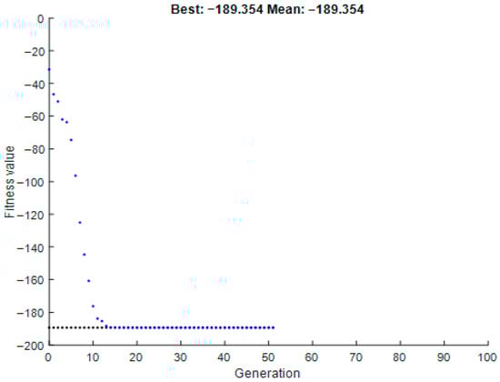
Figure 6.
Fitness curve of the population.
The GA converged after 50 generations, with the best fitness value stabilizing at −189.35 Hz, representing a minimum frequency separation of 189.35 Hz from the excitation range. The mean fitness improved from −46.63 Hz (Generation 1) to −189.35 Hz (Generation 50), indicating consistent progress toward optimality. Stall generations (no improvement) occurred after Generation 20, indicating that the solution had approached a global optimum.
Overall, there was a significant improvement in frequency separation. Using the closest mode (Mode 1), the minimum frequency separation of the engine mount system improved from 162.06 Hz (234.06 − 72) to 189.35 Hz, representing a 16.84% increase. Figure 7 below shows the frequency separation optimization results. The optimized system avoids the entire excitation range (72–336 Hz).
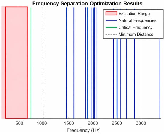
Figure 7.
Frequency separation post-optimization.
From the above GA optimization results, the vibration transmission rate of the engine mount system decreased by approximately 21.51%. This percentage is estimated using the transmissibility formula for a single-degree-of-freedom system near resonance:
where and damping ratio .
At 234.06 Hz (Mode 1), .
Thus, .
After optimization, the new critical frequency becomes 261.35 (72 + 189.35 Hz).
At this frequency, .
Thus, .
The vibration transmissibility, T, decreases from 0.1045 to 0.0821 after optimization, representing a 21.51% decrease.
On its part, L-SHADE optimization achieved a minimum frequency separation of 100.23 Hz, as shown in Figure 8.
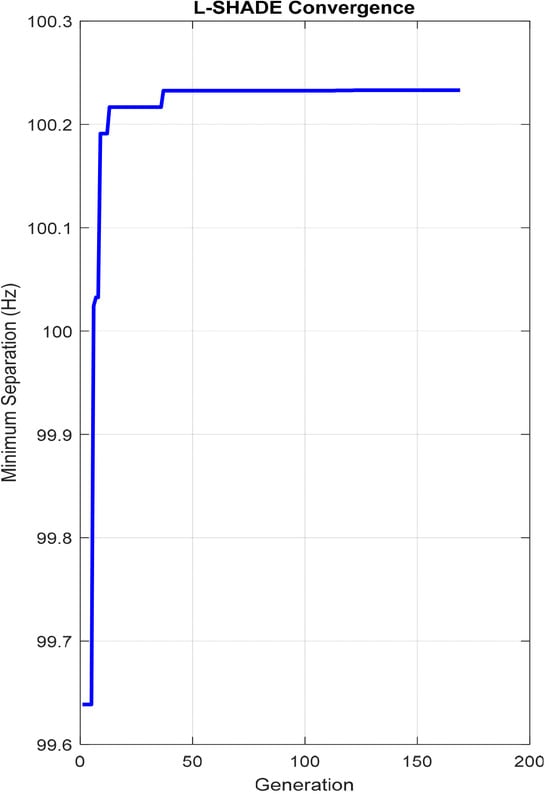
Figure 8.
L-SHADE convergence.
As a result, the critical natural frequency post L-SHADE optimization becomes 172.23 Hz (72 Hz + 100.23 Hz). However, 172.23 Hz is less than the least dominant mode (234.06 Hz). Thus, the study uses 334.29 Hz (234.06 Hz + 100.23 Hz) as the critical natural frequency.
Post L-SHADE optimization,
The vibration transmissibility, T, post L-SHADE optimization decreases from 0.1045 to 0.04820, representing a 53.88% decrease.
3.3. Results Validation
The GA optimization is validated against the system’s excitation range (72–336 Hz), with no natural frequencies occurring below the lower bound of 261.35 Hz (72 + 189.35 Hz) and the upper bound of 336 Hz, which is far above the first optimized natural frequency (≥261.35 Hz).
While the computational analyses that the study employs provide valuable insights into frequency separation and vibration transmissibility reduction in aircraft engine mount systems, experimental validation is essential to corroborate the simulation results.
Previous studies have investigated the vibration-isolation performance of engine mount systems using rigorous experimental methodologies. For instance, a study by NASA focusing on vibration-isolating engine mounts [18] underscores the role of dynamic stiffness and structural flexibility in achieving effective vibration isolation. From this study, it is evident that transmissibility ratio tests can validate the theoretical models used in engine mount design, thus providing empirical frequency response data that align with natural modal frequencies obtained from computational analyses. Similarly, a recent study subjected elastomeric engine mounts to dynamic loading to investigate vibration transmissibility and damping performance across excitation frequencies [19]. The study reported shifts in natural frequencies and a characteristic reduction in transmissibility, thus reinforcing the results obtained in the present study.
4. Discussion
The findings of this study highlight that targeted modal optimization can significantly improve the vibration isolation performance of an aircraft engine mount system. The modal analysis step demonstrated that the first five modes of the system were safely outside the engine’s excitation range of 72–336 Hz. However, several higher-order modes still overlapped with this critical band. If left unaddressed, such overlaps would expose the airframe to resonance and the associated risks of fatigue, discomfort, and reduced structural integrity.
To effectively mitigate these challenges, the study introduced a GA optimization step to fine-tune mount thicknesses and thrust link dimensions. The optimization process produced two key improvements: a 16.84% increase in frequency separation and a 21.51% reduction in vibration transmissibility. These improved outcomes represent a tangible shift in how the mount system responds to engine dynamics. The increased frequency separation creates a buffer zone that keeps natural modes away from operational frequencies, while the reduced transmissibility directly translates into less vibration being transferred to the fuselage.
The results of the L-SHADE optimization affirm the effectiveness of the study’s method by establishing a 53.88% reduction in vibration. The disparity in the two methods’ reduction rates in vibration transmissibility is due to the L-SHADE approach offering better parameter distribution, which enhances accuracy. However, GA is used as the basis of the study, given its advantages for handling discrete, categorical, and mixed design variables.
These results also reaffirm and extend findings from earlier research on vibration isolation. Past work has emphasized the importance of structural flexibility and dynamic stiffness in mount systems. The additions of this study are clear, quantified evidence that careful tuning of geometry through optimization can shift modal frequencies enough to meaningfully enhance isolation.
In essence, the study confirms that modern vibration challenges arising from larger, slower-turning turbofan engines can be addressed through targeted modal optimization. The improved separation and reduced transmissibility achieved here demonstrate a pathway toward mount systems that are lighter, stronger, and more resilient to the dynamic environment of next-generation aircraft.
5. Conclusions
This paper addresses the challenge that most turbofan engines in modern single-aisle airliners operate at frequencies close to their natural frequencies. A genetic algorithm approach based on modal characteristics is applied to enhance the vibration-isolation performance of engine mount systems. A modal analysis is first conducted to identify the dominant modes upon which the optimization is based. The key findings and contributions are summarized as follows:
- Optimized Frequency Separation: The results show that by reasonably adjusting specific physical parameters of the engine mount system, the separation between the excitation frequencies and the natural frequencies can be increased by approximately 16.84%.
- Significant Reduction in Vibration Transmissibility: The optimized design achieved a 21.51% reduction in vibration transmissibility, indicating a significantly improved vibration isolation capability of the mount system.
- Robust and Consistent Optimization Approach: L-SHADE optimization provided an additional benchmark and achieved 53.88% transmissibility reduction. These results also validate the stability and robustness of the GA-derived design while confirming consistency between modern and classical optimization approaches.
- Simplified Simulation-Optimization Integration: The approach presented in this paper offers a simplified but methodologically sound framework for balancing structural stiffness, strength, and vibration control in turbofan engine mount systems.
Future related studies may advance this work by experimentally validating the numerical results through full-scale dynamic testing and integrating the optimized engine mount model into whole-aircraft structural simulations. This approach will help to capture global dynamic interactions, account for nonlinear effects, and establish more comprehensive design guidelines for next-generation aircraft vibration isolation systems. Additionally, strategies such as the surrogate-assisted optimization may be incorporated to allow more nuanced evaluations.
Author Contributions
Conceptualization, M.O.O. and H.D.; methodology, M.O.O. and H.D.; software, M.O.O. and H.D.; validation, M.O.O. and H.D.; formal analysis, M.O.O. and H.D.; investigation, M.O.O. and H.D.; resources, M.O.O., H.D. and C.X.; data curation, M.O.O. and H.D.; writing—original draft preparation, M.O.O. and H.D.; writing—review and editing, M.O.O. and H.D.; visualization, M.O.O. and H.D.; supervision, C.X.; project administration, C.X.; funding acquisition, C.X. All authors have read and agreed to the published version of the manuscript.
Funding
This research received no external funding.
Data Availability Statement
Data is unavailable due to privacy or ethical restrictions.
Acknowledgments
The authors would like to acknowledge their collaborative efforts that made this research possible. Special thanks to our families, friends, and lab mates whose moral support in the course of this study was very instrumental.
Conflicts of Interest
The authors declare no conflicts of interest.
Abbreviations
The following abbreviations are used in this manuscript:
| Damping matrix | |
| External force vector | |
| Gyroscopic matrix | |
| g1 (x) | Stress constraint |
| g2 (x) | Displacement constraint |
| g3 (x) | Mass constraint |
| g4 (x) | Fan blade clearance constraint |
| Frequency response function | |
| Polar moment of inertia | |
| Stiffness matrix | |
| Thrust-induced stiffness | |
| Thrust link length | |
| M | Mass matrix |
| P | Design parameter |
| q | General displacement vector |
| Thrust vector position relative to the center of gravity (CG) | |
| Axial thrust | |
| Aft mount thickness | |
| Forward mount thickness | |
| Transformation matrix | |
| V | Total potential energy |
| W | Thrust link width |
| x | Design variable factor |
| Rotational speed | |
| ω | Frequency |
| Natural frequencies | |
| Yield stress | |
| Von Mises stress | |
| Fan blade tip clearance | |
| Allowable fan blade tip clearance | |
| Maximum displacement | |
| Allowable displacement | |
| Mode shapes | |
| Thermal expansion coefficients | |
| DOF | Degrees of freedom |
| CG | Center of gravity |
| GA | Genetic algorithm |
| CAE | Computer-aided engineering |
| FEM | Finite element method |
| MMPDS | Metallic Materials Properties Development and Standardization |
| NASA | National Aeronautics and Space Administration |
References
- Shim, T.; Margolis, D. Controlled equilibrium mounts for aircraft engine isolation. Control Eng. Pract. 2006, 14, 721–733. [Google Scholar] [CrossRef]
- Tang, J.; Wang, G.; Wu, G.; Miao, Y.; Han, C.; Rui, X. Research on vibration characteristics of aircraft based on MSTMM. In Proceedings of the 1st International Conference on Mechanical System Dynamics (ICMSD 2022), Nanjing, China, 24–27 August 2022; Volume 2022, pp. 526–531. [Google Scholar] [CrossRef]
- Mansfield, J.N.; Aggarwal, G. Whole-Body Vibration Experienced by Pilots, Passengers and Crew in Fixed-Wing Aircraft: A State-of-the-Science Review. Vibration 2022, 5, 110–120. [Google Scholar] [CrossRef]
- Wang, J.-Q.; Nie, Y.-P.; Chen, Y.-H.; Yan, Q.; Chen, C.-L.; Dong, W.-Y. Analysis and Experimental Study on Vibration Isolation Performance of Full-Scale Turbofan Engine Mounting. J. Phys. Conf. Ser. 2024, 43, 1223–1243. [Google Scholar] [CrossRef]
- Phuc, V.D.; Tran, V.T. Optimization design for multiple dynamic vibration absorbers on damped structures using equivalent linearization method. Proc. Inst. Mech. Eng. Part K J. Multi-Body Dyn. 2022, 236, 41–50. [Google Scholar] [CrossRef]
- Barbosa, F.C. Ultra High Bypass Ratio Engine Technology Review—The Efficiency Frontier for the TurbofanPropulsion. SAE Tech. Pap. 2022, 18–19. [Google Scholar] [CrossRef]
- Tejero, F.; Moreno, F.S.; MacManus, D.; Rubio, S.R. Aerodynamics of High-Bypass-Ratio Aeroengine Nacelles: Numerical and Experimental Investigation. J. Aircr. 2025, 62, 4. [Google Scholar] [CrossRef]
- Kuropatwa, M.; Wegrzyn, N.K.J. Turbofan Engines Efficiency, Historical Trends, and Future Prediction: A Review. Saf. Def. 2022, 8, 12–15. Available online: https://sd-magazine.eu/index.php/sd/article/view/186 (accessed on 1 November 2025).
- Giesecke, D.; Lehnler, M.; Friedrichs, J.; Blinstrub, J.; Bertsch, L.; Heinze, W. Evaluation of ultra-high bypass ratio engines for an over-wing aircraft configuration. J. Glob. Power Propuls. Soc. 2018, 2, 493–515. [Google Scholar] [CrossRef]
- Yun, Y. Application of computer simulation technology in modal analysis of engine mount. Vibroeng. Procedia 2023, 52, 74–80. [Google Scholar] [CrossRef]
- Mazzeo, M.; Domenico, D.D.; Quaranta, G.; Santoro, R. Automatic modal identification of bridges based on free vibrations and advanced signal decomposition techniques. Vibroeng. Procedia 2023, 50, 49–55. [Google Scholar] [CrossRef]
- Wang, J.; Ren, G.; Chen, Y.; Yan, Q.; Zhou, R.; Chen, C.; Dong, W. Analysis and verification of vibration isolation performance of engine mount based on low-frequency approximation method. J. Low Freq. Noise Vib. Act. Control 2024, 43, 1223–1243. [Google Scholar] [CrossRef]
- Chen, Y.; Wang, J.; Zhou, R.; Chen, C.; Yan, Q.; Zhang, Z. Research on vibration isolation optimization design technology for the articulated link mount of turbofan engine. J. Phys. 2024, 2736, 12040. [Google Scholar] [CrossRef]
- Chen, C.; Yan, Q.; Chen, Y.; Wang, J.; Xu, J. Parameters Sensitivity Study on Dynamic Characteristics of Turbofan Engine Mounting System. In 2023 Asia-Pacific International Symposium on Aerospace Technology (APISAT 2023) Proceedings; Springer: Singapore, 2024; pp. 728–739. [Google Scholar] [CrossRef]
- Qin, W.; Pan, J.; Ge, P.; Liu, F.; Chen, Z. Dynamic characteristics modeling and optimization for hydraulic engine mounts based on deep neural network coupled with genetic algorithm. Eng. Appl. Artif. Intell. 2024, 130, 107683. [Google Scholar] [CrossRef]
- Tanabe, R.; Fukunaga, A.S. Improving the search performance of SHADE using linear population size reduction. In Proceedings of the 2014 IEEE Congress on Evolutionary Computation (CEC), Beijing, China, 6–11 July 2014; pp. 1658–1665. [Google Scholar] [CrossRef]
- Metallic Materials Properties Development and Standardization (MMPDS). Metallic Materials Properties Development and Standardization Handbook (MMPDS-12); U.S. Department for Transportation-FAA: Washington, DC, USA, 2017; pp. 123–133. Available online: https://www.sae.org/publications/books/content/b-984/ (accessed on 1 November 2025).
- National Aeronautics and Space Administration (NASA). Effect of Structural Flexibility on the Design of Vibration-Isolating Engine Mounts; National Aeronautics and Space Administration (NASA): Washington, DC, USA, 1984; pp. 1–28. Available online: https://ntrs.nasa.gov/api/citations/19840008522/downloads/19840008522.pdf (accessed on 1 November 2025).
- Wang, P.; Su, Z.; Lai, L.; Jiang, H.; Wang, J. Engine Isolate Mount Elastomers. In Proceedings of the International Conference on Structural, Mechanical and Materials Engineering (ICSMME 2015), Dalian, China, 6–8 November 2015; pp. 1–9. [Google Scholar] [CrossRef]
Disclaimer/Publisher’s Note: The statements, opinions and data contained in all publications are solely those of the individual author(s) and contributor(s) and not of MDPI and/or the editor(s). MDPI and/or the editor(s) disclaim responsibility for any injury to people or property resulting from any ideas, methods, instructions or products referred to in the content. |
© 2025 by the authors. Licensee MDPI, Basel, Switzerland. This article is an open access article distributed under the terms and conditions of the Creative Commons Attribution (CC BY) license.