
Research on the Damage Characteristics of a UAV Flight Control System Irradiated by a Continuous Laser

Abstract
1. Introduction
2. Experiment
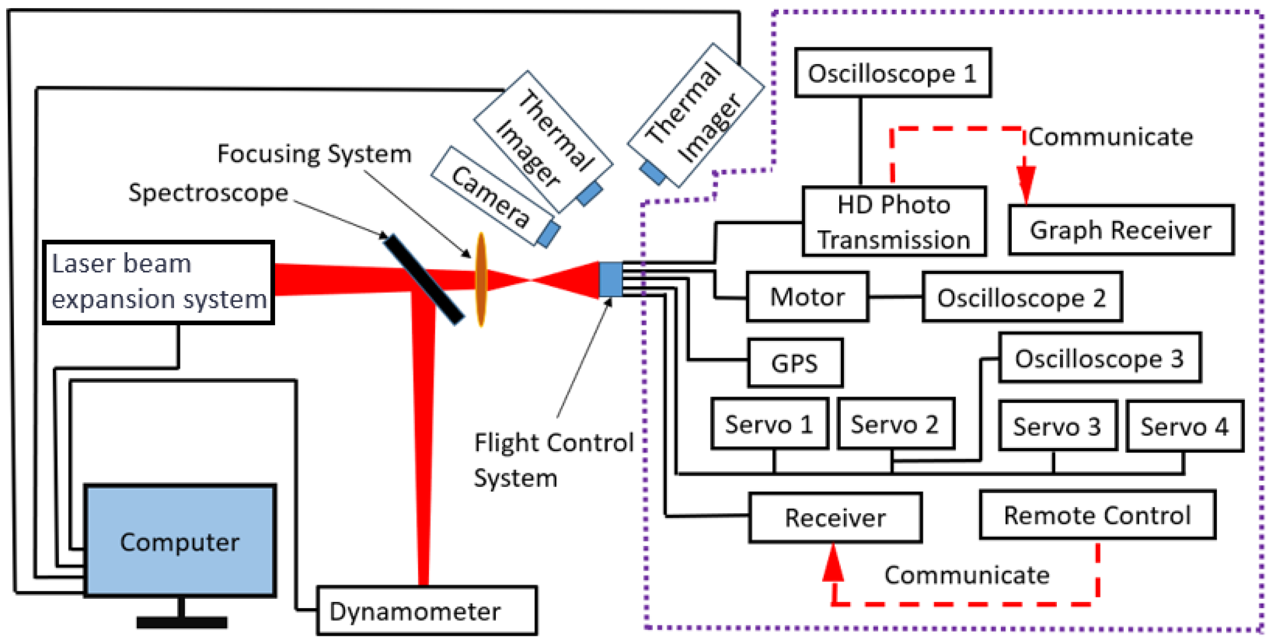
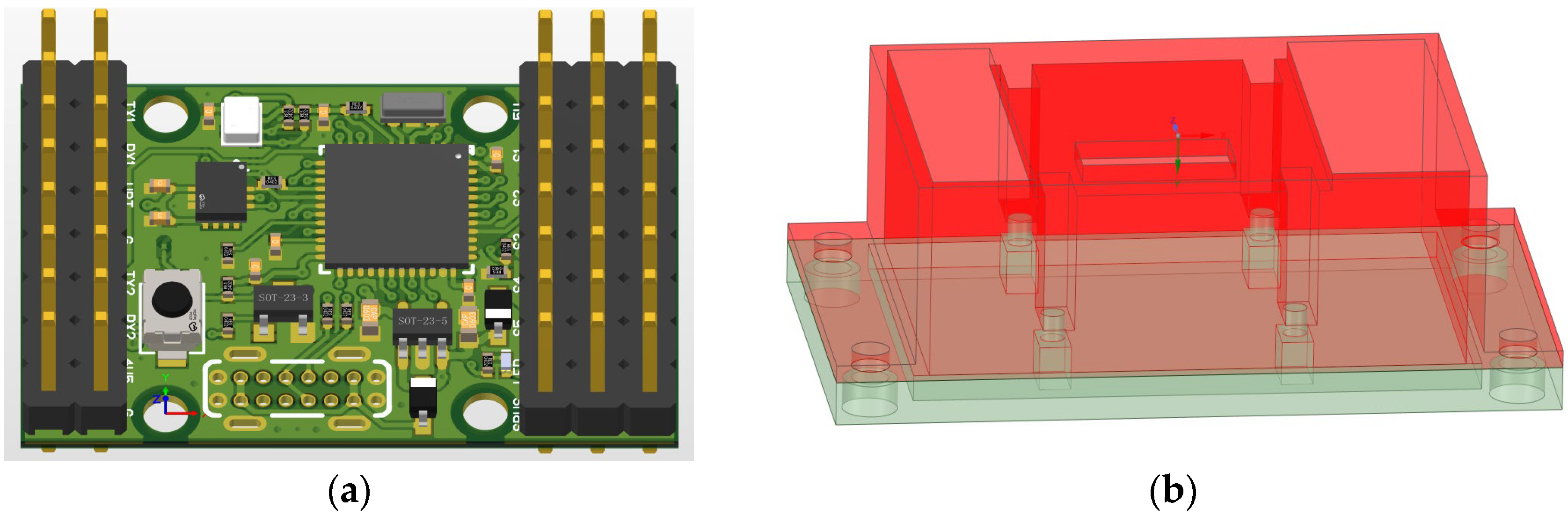
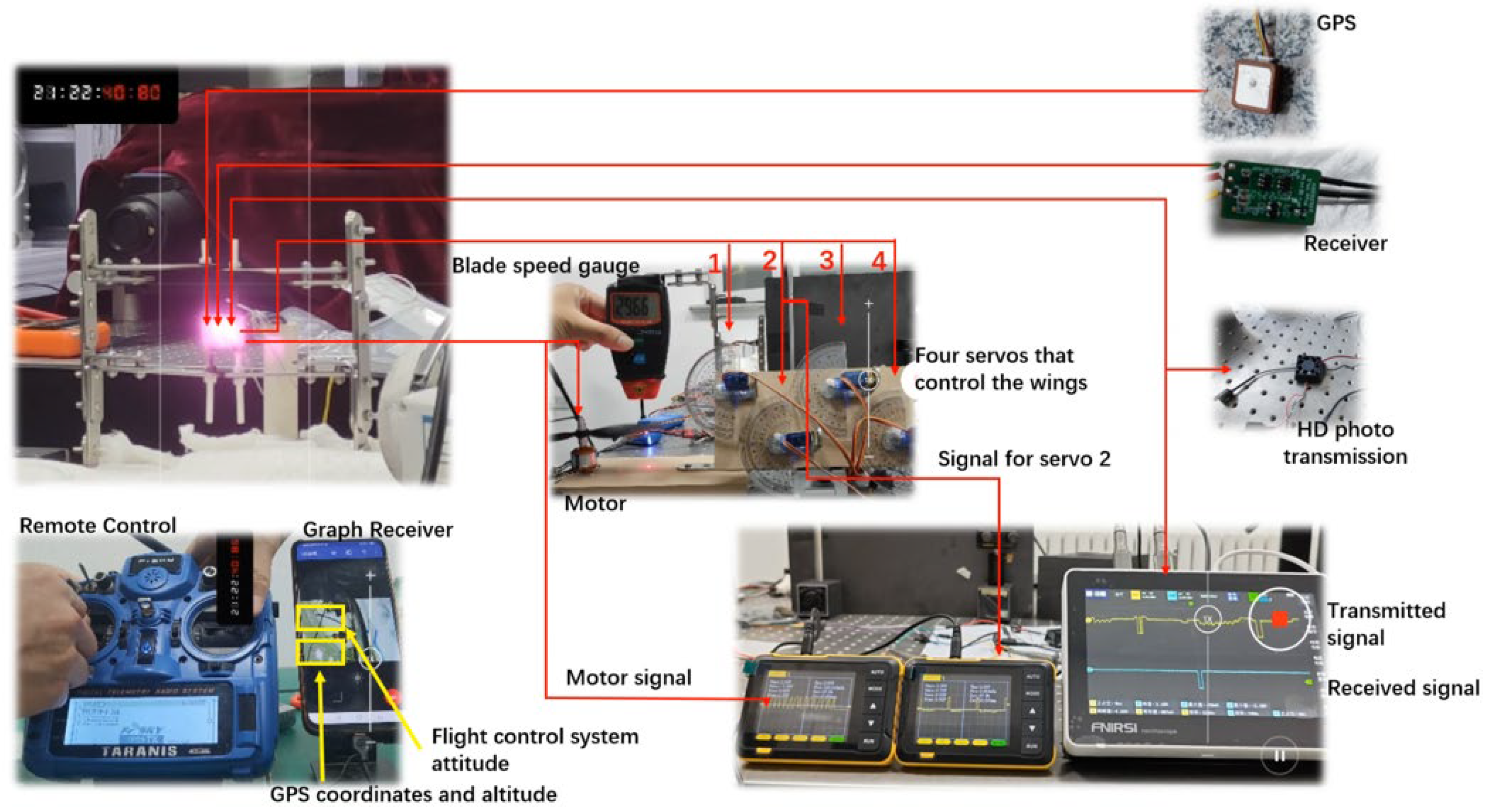
2.1. Experimental Instrument
2.2. Flight Control System Damage Characteristics Test
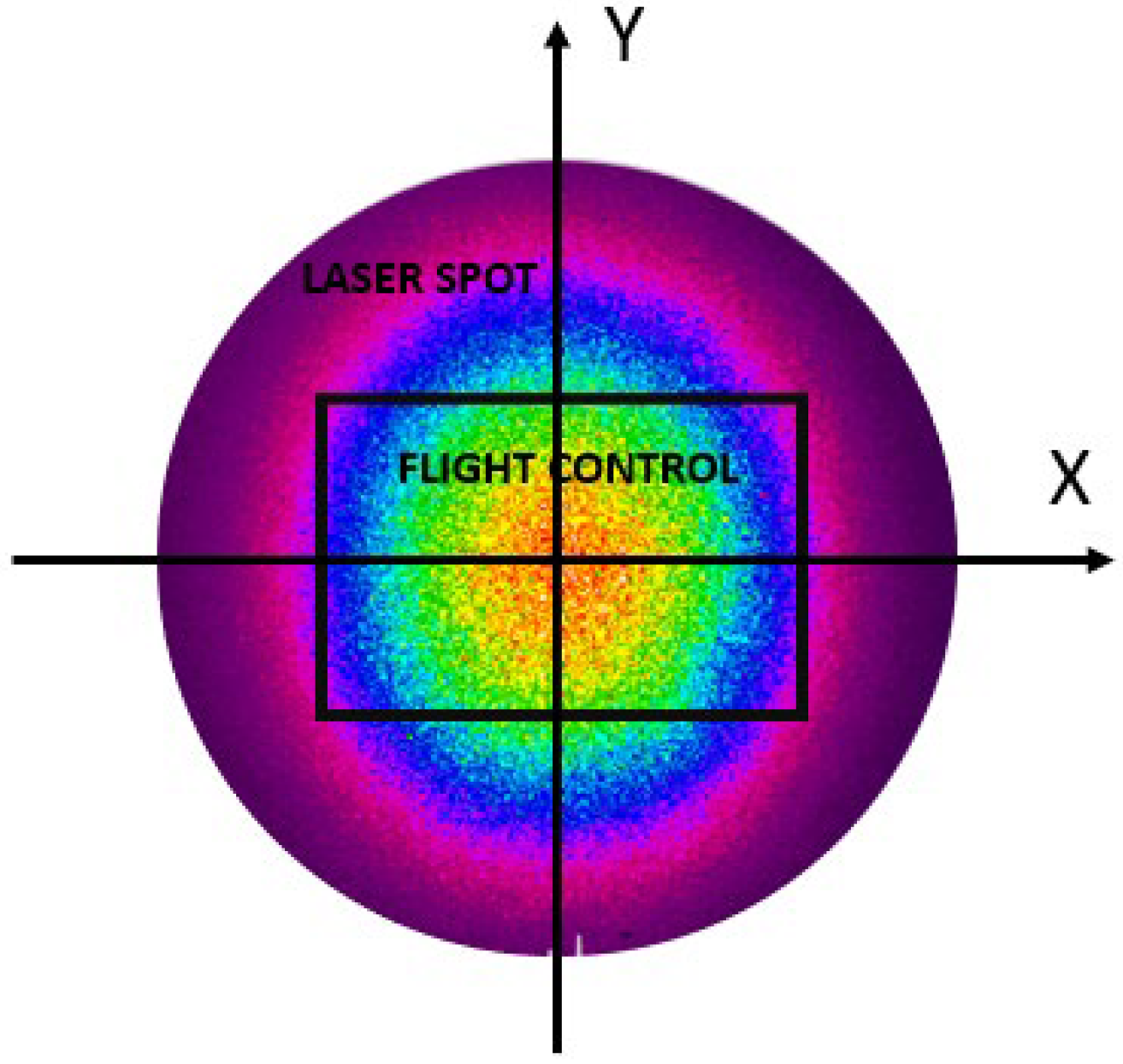
2.3. Power Density Calculation
3. Experimental Results and Analysis
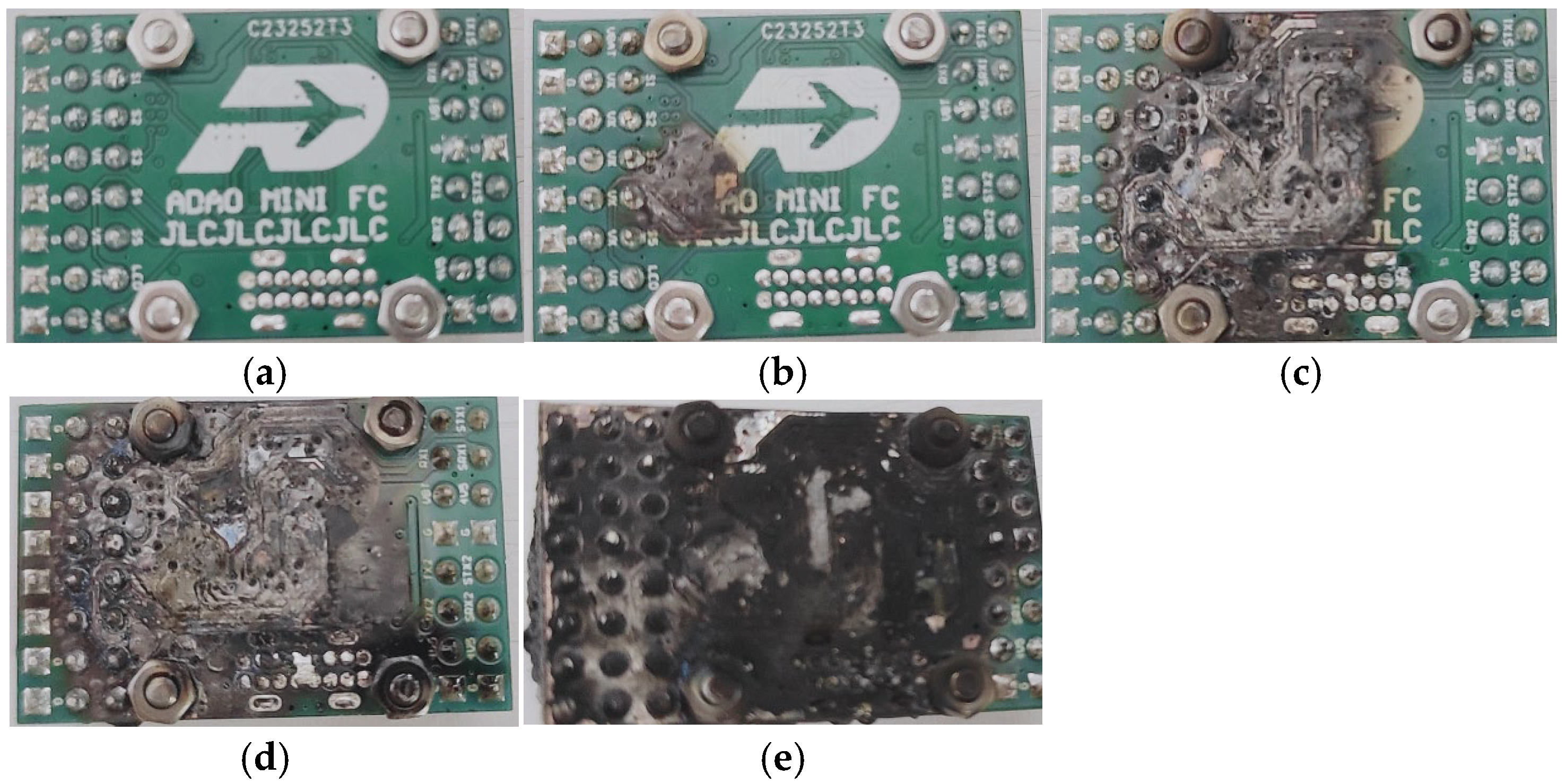
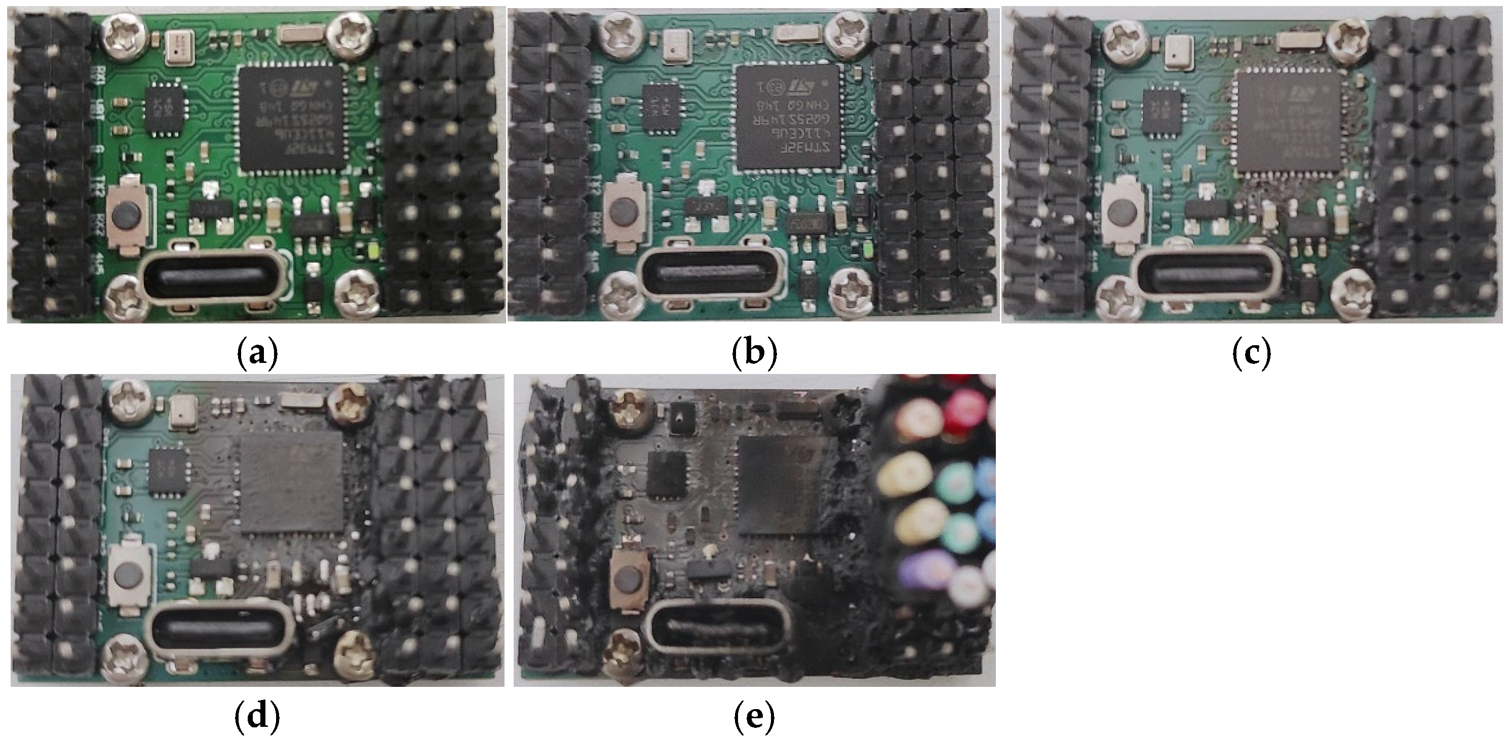
3.1. Ablation Damage
3.2. Functional Damage Characteristics
- No functional failure and no surface damage;
- Temporary functional failure, no surface damage;
- Temporary functional failure, minor surface damage;
- Function is permanently destroyed and the surface is seriously damaged.

| Average Power Density () | Damage Mode | Irradiation Time () | Failure Time () | Ablation Phenomenon | Damage Level |
|---|---|---|---|---|---|
| 14.0 | Temporary failure | 30 | 17.3 | Subtle smoke, no damage | I |
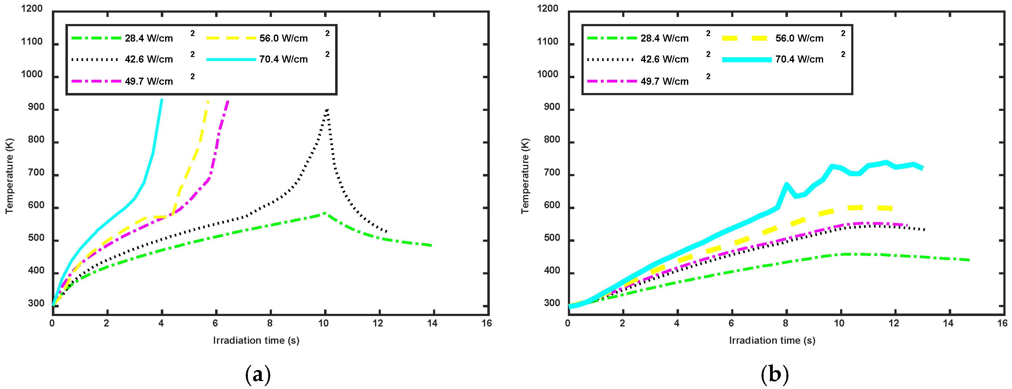
| 28.4 | Temporary failure | 10 | 7–9 | Subtle smoke, no damage | II |
| 35.4 | Temporary failure | 10 | 7–9 | Slightly carbonized | III |
| 42.6 | Permanent damage | 10 | 5–7 | High temperature carbonization | IV |
| 49.7 | Permanent damage | 10 | 5–7 | Tiny flame | IV |
| 56.0 | Permanent damage | 10 | 3–5 | Intense burning | IV |
| 70.4 | Permanent damage | 10 | 3–5 | Continued burning | IV |
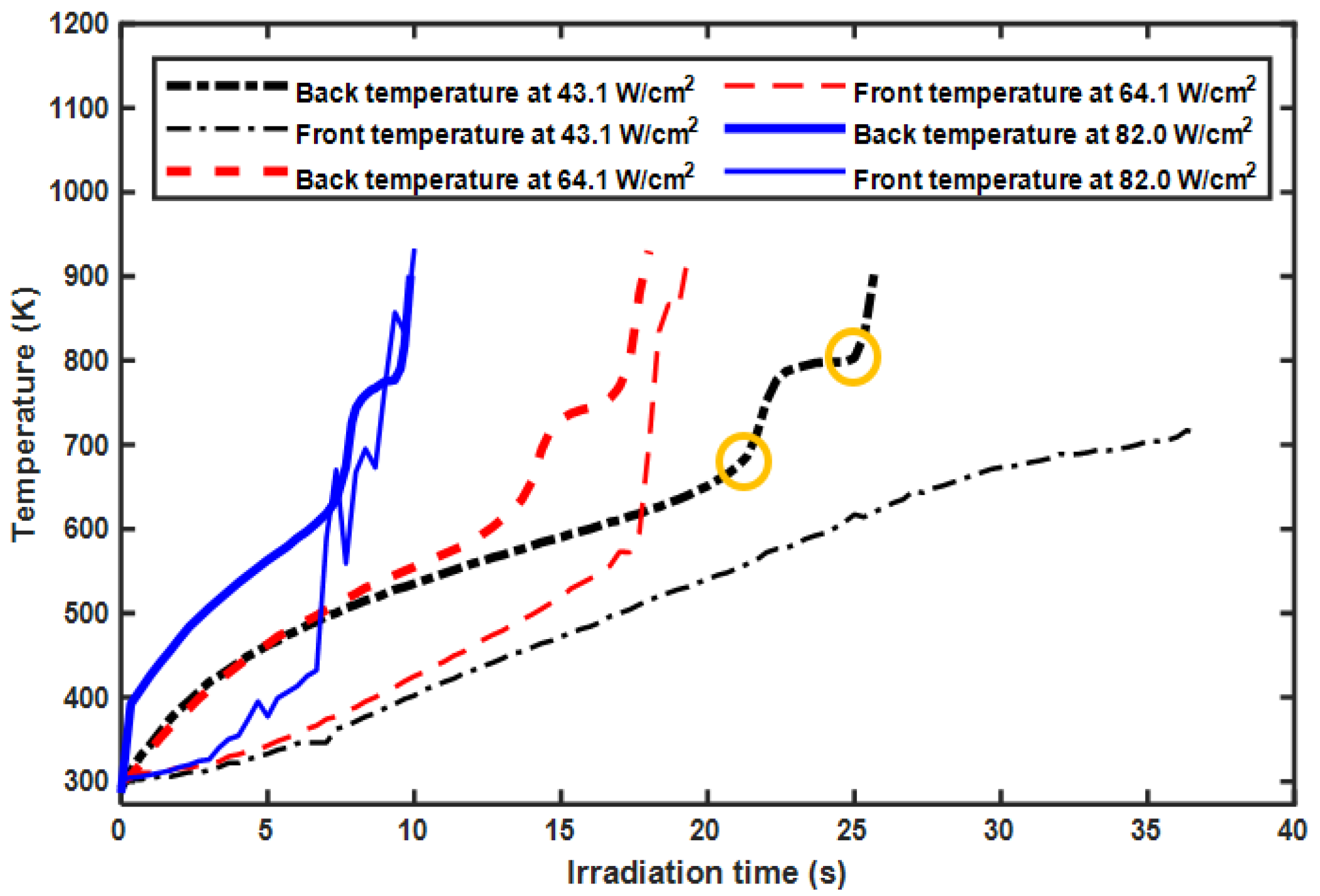
3.3. Flight Control System Damage After Packaging
4. Electronic Damage Characteristics
5. Conclusions
Author Contributions
Funding
Data Availability Statement
Conflicts of Interest
References
- Zhu, M.Z.; Chen, X.; Liu, X.; Tan, C.Y.; Li, W. Situation and key technology of tactical laser anti-UAV. Infrared Laser Eng. 2021, 50, 20200230-1. [Google Scholar]
- Kaushal, H.; Kaddoum, G. Applications of lasers for tactical military operations. IEEE Access 2017, 5, 20736–20753. [Google Scholar] [CrossRef]
- Rahul, S.; Rajeev, V.; Rajiv, K.G.; Harpreet, S. Progress in aerospace materials and ablation resistant Coatings: A focused review. Opt. Laser Technol. 2024, 177, 111160. [Google Scholar]
- Titterton, D.H. Application of laser technology to optical countermeasures. Imaging Sci. J. 2010, 58, 286–294. [Google Scholar] [CrossRef]
- Zhang, Y.; Zheng, C.; Liu, Y.; Wang, Y.; Xu, Y.; Shao, J. Damage Mechanism of HgCdTe Focal Plane Array Detector Irradiated Using Mid-Infrared Pulse Laser. Sensors 2023, 23, 9370. [Google Scholar] [CrossRef] [PubMed]
- Taillandier, M.; Peiffera, R.; Colomerb, B.; Ortizb, R.; Chalumeauc, E.; Pommiesc, M. High-Energy Laser Experiments for Vulnerability Studies in the Context of the European TALOS Program. In High-Power Lasers and Technologies for Optical Countermeasures; SPIE: Bellingham, WA, USA, 2023; p. 12273. [Google Scholar]
- Jiao, L. Study of Laser Irradiation Effects on Liquid Tank. Ph.D. Dissertation, National University of Defense Technology, Changsha, China, 2019. [Google Scholar]
- Dong, Z.Y.; Zhang, W.Q. Drone Flight and Control, 11th ed.; Beihang University Press: Beijing, China, 2020. [Google Scholar]
- Liu, L.; Xu, C.Y.; Zheng, C.B.; Cai, S.; Wang, C.R.; Guo, J. Vulnerability assessment of UAV engine to laser based on improved shotline method. Def. Technol. 2023, 33, 588–600. [Google Scholar] [CrossRef]
- Pei, Y.; Song, B.F. Method for assessing unmanned aerial vehicle vulnerability to high-energy laser weapon. J. Aircr. 2012, 49, 319–323. [Google Scholar] [CrossRef]
- Zhou, Z.; Chen, J.; Yu, C.; Wang, Y.; Zhang, Y. Failure Analysis of Printed Circuit Board Solder Joint under Thermal Shock. Coatings 2023, 13, 572. [Google Scholar] [CrossRef]
- Slee, D.; Stepan, J.; Wei, W.; Swart, J. Introduction to printed circuit board failures. In Proceedings of the 2009 IEEE Symposium on Product Compliance Engineering, Toronto, ON, Canada, 26–28 October 2009. [Google Scholar]
- Li, T. Study on Flux Component of Snagcu Lead-Free Solder Paste and Its Effect on Corrosion Property of Solders. Master’s Dissertation, Xi’an University of Technology, Xi’an, China, 2009. [Google Scholar]
- TWGWC, 1N5817WS THRU 1N5819WS. Available online: https://datasheet.eeworld.com.cn/view/67220954.html?u_atoken=e7da4209c1d5f588be6c06671b0e1661&u_asig=2760821417216625961556744e449a (accessed on 13 June 2024).
- MicrOne, High Speed LDO Regulators, High PSRR, Low Noise, ME6211 Series General Description. Available online: https://file.elecfans.com/web2/M00/72/4D/poYBAGNVHsuAAvouABV6l3c8qJQ275.pdf (accessed on 13 June 2024).
- Guilin Strong Micro-Electronics Co.Ltd. S8050 Technical Specifications. Available online: https://wenku.baidu.com/view/fe73c3eb19e8b8f67c1cb9f3.html?fr=sogou&_wkts_=1723133736986&needWelcomeRecommand=1 (accessed on 13 June 2024).
- Peng, J.; Yuan, B.; Sun, X.; Chen, Y.; Chen, H. Research on Penetration Behavior and after effects of Coated Reactive Fragments Impacting Steel targets. Int. J. Multiphysics 2020, 14, 39. [Google Scholar]
- Yu, X.Y.; Yue, M.K.; Liang, Z.G. Numerical Simulation of Aftereffect Power of Shaped Charge JET Penetrating Steel Target. In Proceedings of the 2nd International Conference on Machine Learning and Computer Application, Dhaka, Bangladesh, 10–12 March 2022. [Google Scholar]
- Wang, W.B.; Zhang, K.H.; Yu, K. A comparative research on the infrared spectral emissivity of Al5052 and Al6061. J. Xingyi Norm. Univ. Natl. 2015, 4, 110. [Google Scholar]
- Wen, K.; Li, H.Z.; Ma, Z.; Gao, L.H.; Wang, F.C.; Li, W.Z. Effects of spot size on the temperature response of an aluminum alloy irradiated by a continuous laser. Chin. Opt. 2020, 13, 1023–1031. [Google Scholar]
- Wei, Y.B. Evaluation of Laser Target Damage Effectiveness. Master’s Dissertation, University of Electronic Science and Technology of China, Chengdu, China, 2019. [Google Scholar]
- Xiong, L.J.; Wang, J.W.; Nie, G.H. Analysis of Ablation and Strength of CFRP Laminated Structures under Laser irradiation. Chin. Q. Mech. 2022, 43, 771–781. [Google Scholar]
- Zhao, W.N.; Huang, Y.H.; Song, H.W.; Huang, C.G. Multi-Scale Analysis Model of Thermal-Mechanical Damage Effect in High-Power Continuous-Wave Laser Irradiation of CFRP Laminates. Chin. J. Lasers 2017, 44, 602003. [Google Scholar]


| Average Power Density () | Damage Mode | Irradiation Time () | Failure Time () | Ablation Phenomenon | Damage Level |
|---|---|---|---|---|---|
| 43.1 | Permanent damage | 32 | 25–35 | High temperature carbonization | IV |
| 64.1 | Permanent damage | 26 | 15–25 | Intense burning | IV |
| 82.0 | Permanent damage | 16 | 10–15 | Intense burning | IV |
Disclaimer/Publisher’s Note: The statements, opinions and data contained in all publications are solely those of the individual author(s) and contributor(s) and not of MDPI and/or the editor(s). MDPI and/or the editor(s) disclaim responsibility for any injury to people or property resulting from any ideas, methods, instructions or products referred to in the content. |
© 2025 by the authors. Licensee MDPI, Basel, Switzerland. This article is an open access article distributed under the terms and conditions of the Creative Commons Attribution (CC BY) license (https://creativecommons.org/licenses/by/4.0/).
Share and Cite
Liu, L.; Xu, C.; Cai, S.; Wang, J.; Huang, D.; Yang, K.; Zheng, C.; Guo, J. Research on the Damage Characteristics of a UAV Flight Control System Irradiated by a Continuous Laser. Aerospace 2025, 12, 161. https://doi.org/10.3390/aerospace12020161
Liu L, Xu C, Cai S, Wang J, Huang D, Yang K, Zheng C, Guo J. Research on the Damage Characteristics of a UAV Flight Control System Irradiated by a Continuous Laser. Aerospace. 2025; 12(2):161. https://doi.org/10.3390/aerospace12020161
Chicago/Turabian StyleLiu, Le, Chengyang Xu, Sheng Cai, Jiamin Wang, Dandan Huang, Kun Yang, Changbin Zheng, and Jin Guo. 2025. "Research on the Damage Characteristics of a UAV Flight Control System Irradiated by a Continuous Laser" Aerospace 12, no. 2: 161. https://doi.org/10.3390/aerospace12020161
APA StyleLiu, L., Xu, C., Cai, S., Wang, J., Huang, D., Yang, K., Zheng, C., & Guo, J. (2025). Research on the Damage Characteristics of a UAV Flight Control System Irradiated by a Continuous Laser. Aerospace, 12(2), 161. https://doi.org/10.3390/aerospace12020161