Abstract
The tail boom is a critical structural component of a helicopter, and accurately capturing its dynamic characteristics is essential; however, the inherent geometric and material complexity of the tail boom usually leads to large-scale finite element models whose system matrices are of very high order, and as the matrix order increases the computational effort grows exponentially. To further accelerate the condensation process for a truss-type tail-boom FE model, this paper presents a substructure-based secondary condensation method in which the global structure is partitioned into several substructures, each secondary substructure is first condensed onto its boundary nodes and then assembled into the primary structure, and the primary structure—now enriched with the condensed secondary substructures—is finally reduced to the target degrees of freedom, repeatedly operating on low-order matrices instead of a single high-order one to markedly shorten overall computation time. The proposed method is compared with both overall secondary IRS condensation and overall secondary SEREP condensation. All three secondary-condensation strategies yield six-degree-of-freedom coupled-spring equivalent models whose accuracy errors are very small in modal, frequency-domain, and time-domain analyses: frequency errors remain within 1%, and the goodness-of-fit of the time-history response curves exceeds 0.9, while the computational time is reduced by more than 70%, demonstrating that the substructure-based secondary condensation method is highly effective, delivering much higher computational efficiency without sacrificing accuracy.
1. Introduction
The helicopter tail boom is an important part of the helicopter fuselage, playing a decisive role in the helicopter’s balance and the execution of various flight maneuvers such as turning, hovering, and cruising [1]. Due to the complexity of operating conditions, the helicopter tail boom inevitably undergoes complex vibrations, such as time responses of the wings and tail, and fuselage vibration behaviors [2]. Its vibration level directly affects the stability of the helicopter’s tail drive system and the overall vibration level of the helicopter [3]. Therefore, analyzing its dynamic behavior is crucial for helicopter safety, and vibration characteristics serve as an important foundation for harmonic response analysis of the tail structure [4], robust controllers [5], and numerical studies for fatigue life prediction [6]. Natural frequency is the most important vibration characteristic, and various methods exist for calculating the natural frequencies of helicopter systems, such as dynamic topology models, total transfer equations, and characteristic equations [7]. For complex structures, finite-element analysis is generally used; however, if the structural geometry is complex, in order to obtain detailed displacement and stress state information, the structure is often divided into a large number of elements, resulting in a total structural freedom count reaching hundreds of thousands or even millions. During computational analysis, this leads to large-scale computation, long computation time, and massive computational results occupying significant disk space. Displaying the overall model results in such large computational files also requires considerable time.
Model condensation [8] is a commonly used technique for reducing the number of degrees of freedom and the attendant computational burden; its essence lies in preserving the dominant dynamic characteristics of the original system—such as frequency and damping properties [9]—so that analyses under complex conditions can be performed more efficiently. The Guyan condensation [10] is the simplest and most classical model condensation method; however, because inertial terms are neglected, the reduced model exhibits very low accuracy in dynamic analyses. Building upon the Guyan method, O’Callahan [11] proposed the Improved Reduced System (IRS) condensation, which retains the first-order inertial terms of the reduced model via a Neumann-series expansion, thereby markedly enhancing dynamic accuracy. Friswell et al. [12] further advanced the IRS approach by introducing the iterated IRS (IIRS) condensation, in which each iteration adds one order of inertial terms from the Neumann expansion, progressively approaching the exact solution and significantly improving the accuracy of the reduced model in medium- and high-frequency dynamic analyses. Yang Qiu-wei [13,14] and co-workers, also starting from the IRS formulation, developed an improved IRS method that accounts for second-order inertial terms; compared with IIRS, this approach yields higher accuracy for higher-order frequencies in truss and frame structures. Additionally, in 1989, O’Callahan et al. [15] proposed the SEREP (System Equivalent Reduction Expansion Process) condensation, which realizes condensation and expansion of degrees of freedom through the pseudo-inverse of the modal matrix and likewise enables substantial reduction in computational scale while preserving the original model’s dynamic characteristics within a specified frequency range. Li Jian et al. [16] enhanced SEREP by introducing extended master degrees of freedom to increase the dimension of the linear subspace corresponding to the reduced model, thereby further improving accuracy. With the development of machine learning, surrogate-model techniques such as the response-surface method [17,18], artificial neural networks [19], and Kriging/Gaussian-process regression [20,21] have also flourished [22]; however, these approaches only approximate the input–output relationship of the original FE model through a low-dimensional mapping and no longer retain physical matrices.
Bhat [23] applied Guyan condensation to externally excited nonlinear quasi-periodic systems. Mao et al. [24] applied the Improved Reduction System (IRS) condensation method to vibration analysis of structures such as cylindrical curved plates and crankshafts, validating the engineering feasibility of the IRS condensation method. Aglietti et al. [25] employed SEREP condensation on the Aeolus satellite and provided a master-degree-of-freedom selection strategy to improve the accuracy of reduced models. Li Jian et al. [16] achieved high-precision condensation of a spacecraft vibration-isolation platform using an improved SEREP approach. The above condensation methods are typically applied only once within a structure and can therefore be referred to as single-step condensation methods. Currently, reduced models commonly used for analyzing complex tail-boom systems are obtained via “single-step condensation technology”, i.e., the tail-boom FE model is first established and then directly reduced to the hub center at the tail-boom/tail-rotor interface using the fixed-interface modal synthesis method [26,27,28] to generate the tail-boom reduced model.
Dynamic-simulation studies of helicopter dynamic characteristics cannot dispense with the tail boom; however, the complex structure of the tail boom sometimes incurs enormous computational cost. The most time-consuming step in condensation is the inversion of large-scale system matrices; according to the computational principle of Gaussian elimination for matrix inversion, the time complexity of this step is
, and the number of inversion operations increases exponentially with the number of degrees of freedom in the model, usually accounting for more than 70% of the total condensation time. To save computational time during condensation, a two-step condensation method can be adopted to reduce the number of degrees of freedom involved in each operation; how to partition the degrees of freedom involved in each operation thus becomes a new research topic. In model condensation, the number of master degrees of freedom selected empirically or randomly generally ranges from tens to hundreds; consequently, for large FE models with total degrees of freedom on the order of tens or even millions, the reduction achieved in the first condensation is almost negligible.
The substructure method [29,30] divides a complex structure into several independent sub-domains according to a certain strategy, condenses the internal degrees of freedom onto the boundaries, and then assembles the substructures in accordance with the original interface geometric continuity principle, thereby significantly reducing matrix size and achieving simultaneous decreases in computational effort and storage requirements. Yang et al. [31] applied the substructure method to a submarine compartment model, avoiding the need to re-analyze the entire structure when local parameters are modified and lowering computational costs while maintaining simulation accuracy. Furthermore, using a substructure-based reduced model instead of the physical model for mechanical analyses can prevent the disclosure of detailed structural-design information during external collaboration, thus providing technical confidentiality; for example, in launch-vehicle–spacecraft coupling analyses [32], modeling details of large components, such as space-borne cameras and helium tanks, can be hidden, and only the reduced model with boundary conditions needs to be submitted.
In this paper, a truss-type helicopter tail-boom model is divided into two parts; first, the substructure method is used to condense the secondary substructure FE model onto a set of fixed-interface boundary nodes, yielding a single-step reduced mathematical model of the secondary substructure. Next, nodes exhibiting the largest vibration response in the hybrid model containing the once-reduced substructure are selected as solution points for a second condensation, achieving a substantial reduction in the time required for the condensation process. A comparison with applying the two-step IRS condensation to the entire tail-boom model demonstrates that the substructure-based two-step condensation method offers higher computational efficiency.
2. Model Condensation Theory
The principle of model condensation is to perform a coordinate transformation on the original model, and derive the degree-of-freedom transformation matrix
, and perform the transformation
,
, reducing the degrees of freedom of the original model, where
,
are the mass and stiffness matrices before condensation, and
,
are the mass and stiffness matrices after condensation. Different condensation methods have different transformation matrices
. This section presents three common condensation methods: IRS condensation, SEREP condensation, and substructure method.
2.1. IRS Condensation Method
The IRS condensation method improves accuracy by adding inertia terms based on Guyan static condensation and can further improve model condensation accuracy through iterative operations. Its principle is as follows:
The structural motion differential equation is:
The structural degrees of freedom
are divided into master degrees of freedom
and slave degrees of freedom
, Subscript “a” denotes master degrees of freedom, and subscript “b” denotes slave degrees of freedom.
and
represent the forces applied to the master and slave degrees of freedom, respectively. After adjusting the positions of elements in the mass and stiffness matrices according to master and slave degrees of freedom using partitioned matrices, the characteristic equation can be written as:
In the frequency domain, it is represented by block matrices as:
The expansion yields:
Expanding into Neumann series [33]
, gives:
Ignoring the off-diagonal elements of the mass matrix, simplifying to:
If the inertia term is removed, it is the Guyan condensation method.
For the first-order IRS condensation method, retaining the first-order inertia term, the degree of freedom transformation matrix is:
Among them,
is the Guyan condensation matrix,
,
are the mass, stiffness matrices after Guyan condensation, and
, the zero matrix dimension is related to the dimension of
,
. If the second-order inertia term is retained, the degree of freedom transformation matrix is:
At this time, it is called the second-order IRS condensation method.
Iterating the above until the relative error of adjacent eigenvalues satisfies a prescribed tolerance yields the iterated IRS condensation (IIRS).
If damping is considered, the motion equation becomes:
For easy solution, let the damping be proportional, that is:
Then the condensation damping matrix is:
It can be seen that this condensation method satisfies linear properties.
The
matrix of the IRS method only involves inversion and does not involve solving eigenvectors.
2.2. SEREP Condensation
The SEREP method is built upon modal analysis; therefore, the first step is to perform an eigenvalue analysis of the finite-element model to obtain the first
eigenvalues
and eigenvectors
. The associated eigenvalue problem is
The eigenvectors are then partitioned according to master (
) and slave (
) degrees of freedom:
where
denotes the number of master DOFs and
the number of slave DOFs.
Introducing the concept of pseudoinverse, let
denote the pseudoinverse of the
matrix
. The SEREP condensation transformation matrix
is
where
is computed as
2.3. Substructure-Based Condensation
The substructure-based condensation method [18] condenses the stiffness and mass information of the nodes of a substructure in the finite element physical model on the boundary points to generate a condensation model.
The stiffness matrix and mass matrix of the secondary structure after the first condensation are:
Where the condensation transformation matrix
is [34]:
represents the degrees of freedom of the fixed interface boundary points,
represents the degrees of freedom of the free interface boundary points,
represents the remaining internal degrees of freedom set. It can be seen that the
matrix of the substructure method not only involves inversion but also involves solving eigenvectors, and the calculation is larger. The following provides a new method of condensing the substructure on the boundary points.
After the matrix of the secondary structure is condensed, it should be connected to the main structure. Suppose as shown in Figure 1, nodes a, b are connected to points
,
on the ground with springs of stiffness
,
. When not connected to the spring, it is known that the stiffness matrix is:
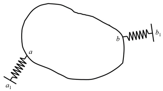
Figure 1.
Structure of spring connection.
When the spring is connected, according to the assembly method of the stiffness matrix, the stiffness matrix can be obtained as
Since points
and
on the ground are fixed points, the stiffness matrix of the structure, obtained by deleting rows and columns from Equation (19), is
Condensing the information of the substructure on the boundary points, that is, condensing with the nodes on the boundary as the master degrees of freedom, is equivalent to replacing the substructure with springs, and then using the above method to assemble the stiffness matrix, as shown in Figure 2. Among them, na is the number of degrees of freedom of substructure A, and nb is the number of degrees of freedom of substructure B.
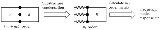
Figure 2.
Schematic diagram of condensation method steps based on substructure method.
3. Secondary Condensation Simulation Calculation of Helicopter Tail Boom
Figure 3 shows an aluminum helicopter tail-boom model consisting of a variable-cross-section L-shaped truss beam; detailed dimensions are given in Figure 4. The model comprises members with rectangular and circular cross-sections; axial members are circular (Φ5 mm) and hoops rectangular (20 mm × 2 mm), tapering proportionally along segments 0–400 mm and 400–1890 mm. Material properties: aluminum alloy, Young’s modulus E = 69.2 GPa, Poisson’s ratio 0.33, density 2713 kg/m3. The front end is elastically supported to simulate the connection between fuselage and tail boom; the connection is idealized as three translational and three rotational springs whose stiffnesses are listed in Table 1.
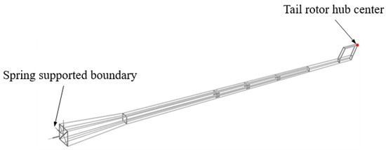
Figure 3.
A helicopter tail boom model with a certain framework.
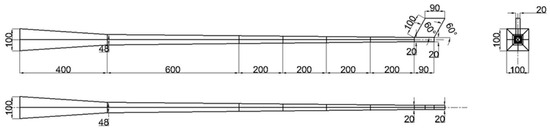
Figure 4.
Three views of tail beam model.

Table 1.
Spring stiffness coefficients of the elastic support tail boom model.
The node at the center of the hub on the tail beam is located at the corner of the tail beam end, which is usually the most easily damaged part of the entire tail beam [35]. If both the tail boom and tail rotor are modeled simultaneously in simulation, the computational load will be extremely large, making it difficult to analyze the causes of tail boom failure. To quickly obtain dynamic simulation data at the tail boom rotor hub center, the tail boom needs to be simplified. The ideal simplification is to equivalently represent the tail boom as a 6-DOF coupled spring, resulting in a 6-DOF equivalent model of the tail rotor, significantly reducing computational load.
After constructing the tail-boom model in ANSYS 2024 R2, mesh refinement is carried out until the first four natural frequencies converge. Table 2 lists the first four frequencies versus element size; when the beam-element size is 12 mm (1721 elements), the first four frequencies are fully converged, and this mesh is adopted for subsequent study.
Table 2.
The relationship between the number of units and the first four order frequencies.
The complete model contains 3393 nodes, each with 6 DOF (three translations and three rotations), yielding 20358 DOF in total. The mass and stiffness matrices are exported from ANSYS in sparse HBmat (Harwell–Boeing matrix) format and imported into MATLAB for further computation.
3.1. Secondary Dynamic Condensation Methods
Three secondary condensation schemes are implemented: Method a: overall secondary IRS condensation; Method b: overall secondary SEREP condensation; Method c: substructure-based secondary condensation.
3.1.1. Selection Scheme of Master Degrees of Freedom Using the Overall Secondary Condensation
Method a and Method b have the same scheme for selecting the master degrees of freedom during the secondary condensation process. First, using the model shown in Figure 5a (total degrees of freedom 20,358), 66 degrees of freedom from 11 nodes are selected as master degrees of freedom for first-order condensation, yielding the first-order condensed model shown in Figure 5b. Then, the first-order condensed model is further condensed using 6 degrees of freedom from the rotor hub center node as master degrees of freedom for second-order condensation, resulting in a 6 × 6 matrix. The simplified model is shown in Figure 5c. If it is directly condensed from Figure 5a–c, it is a single-step condensation method.
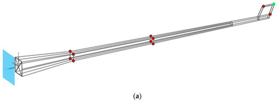
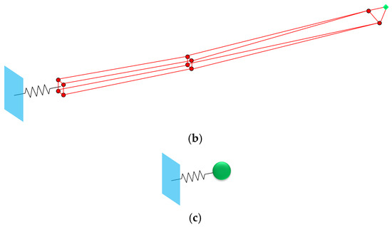
Figure 5.
Simplified model using overall secondary condensation. (a) Original Model (Order: 20358), (b) First-Order Condensed Model (Order: 66), (c) Second-Order Condensed Model (Order: 6).
3.1.2. Partition Scheme of Substructure Based on Substructure Method in Secondary Condensation
The model is divided into the beam body and tail wing, as shown in Figure 6a, with degrees of freedom 11202 and 9156, respectively. First, the beam body is condensed using 24 degrees of freedom from 4 connection points as main degrees of freedom for first-order IRS condensation, then connected to the tail wing, obtaining the first-order condensed matrix, as shown in Figure 6b. Then, the first-order condensed matrix is further condensed using the rotor hub center as master degrees of freedom for second-order condensation, resulting in a 6 × 6 matrix. This method can also be understood as using the substructure method twice: first condensing the beam body as a substructure to connection points, then condensing the tail wing, excluding the rotor hub center as a substructure to the rotor hub center. The simplified model is shown in Figure 6c.
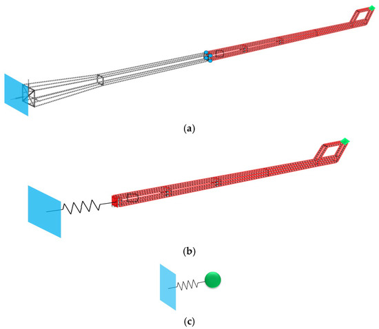
Figure 6.
Simplified model using substructure-based secondary condensation method. (a) Original Model (Order: 20358), (b) First-Order Condensed Model (Order: 9156), (c) Second-Order Condensed Model (Order: 6).
3.2. Harmonic Response Analysis
Modal analysis is performed on the uncondensed model and models obtained using the overall secondary IRS condensation and substructure-based secondary condensation methods. The first four key natural frequencies and mode shapes are shown in Table 3.
Table 3.
First Four Natural Frequencies and Mode Shapes of Tail Boom.
Harmonic excitation with amplitude 10 N is applied horizontally inward (Y-direction) and vertically downward (Z-direction) at the rotor hub center node of the tail boom models obtained using the overall secondary IRS condensation, overall secondary SEREP condensation and substructure-based secondary condensation methods.
The harmonic response curves under horizontal inward excitation are shown in Figure 7. Resonance occurs at the first and second horizontal natural frequencies, consistent with vibration theory. The harmonic response curves of the uncondensed, overall secondary IRS condensation, overall secondary SEREP condensation and substructure-based secondary condensation models match well near resonance peaks.

Figure 7.
Y-Direction Frequency-Response Curve.
The harmonic response curves under vertical downward excitation are shown in Figure 8. Resonance occurs at the first and second vertical natural frequencies, and the harmonic response curves of the uncondensed, overall secondary IRS condensation, overall secondary SEREP condensation and substructure-based secondary condensation models almost completely overlap.

Figure 8.
Z-Direction Frequency-Response Curve.
3.3. Time Domain Analysis
Harmonic response analysis shows that all secondary condensation methods yield highly accurate condensed models in the frequency domain. Time-domain analysis is performed on the condensed models. Excitations applied at the rotor hub center are: (a) vertical downward 10 N amplitude at 1st vertical resonance frequency 6.90 Hz; (b) vertical downward 10 N amplitude at 2nd vertical resonance frequency 15.85 Hz; (c) vertical downward 10 N amplitude at non-resonant frequency 10 Hz; (d) vertical downward step load 10 N.
The time-history response curves for the four cases are shown in Figure 9. Except for slight differences at 1st resonance frequency, the time-history curves of the condensed models obtained using overall secondary IRS condensation, overall secondary SEREP condensation and substructure-based secondary condensation match well with the uncondensed model.
Figure 9.
Vertical displacement time history curve at the hub center under different working conditions.
For harmonic-excitation cases a, b, and c, the goodness of fit
is employed to evaluate the agreement between the time-history response curves obtained from the three secondary condensation models and those of the uncondensation model. The formula is
where
is the index of data points on the curve,
is the total number of data points,
is the value of the test curve,
is the value of the target curve, and,
is the mean value of the test curve. The closer
is to 1, the better the agreement between the actual and target curves; in general,
is regarded as a good fit. The goodness of fit of the time history response curves of the condensation model and the no condensation model obtained by the three methods under three different operating conditions, a, b, and c, is shown in Table 4, indicating that the goodness of fit is above 0.9.
Table 4.
Coefficient of determination.
For the sudden-step load case d, the ratio of the static displacement after the system reaches steady state to the corresponding element value at the same data-index point in the unreduced system’s static-displacement response is used to measure the agreement between the response curves. For case d, this ratio is 0.96, 0.92, 0.97, which also demonstrates good agreement.
Harmonic-response and time-domain analyses show that the condensed models obtained by either the overall secondary IRS condensation method, overall secondary SEREP condensation or the substructure-based secondary condensation method possess sufficient accuracy. Therefore, in subsequent predictions of complex dynamic responses at the tail-boom rotor-hub center, either condensed model can be used in place of the original full-order model to achieve higher computational efficiency.
3.4. Condensation Time Analysis
During the process of using IRS condensation and substructure method condensation, the main time-consuming part is matrix inversion. The commonly used matrix inversion methods, such as Gaussian elimination, LU decomposition, and Cholesky decomposition, all have a time complexity of
.
Using overall secondary condensation, the first condensation matrix inversion is of order 20358 − 66 = 20292, and the second condensation inversion is of order 66 − 6 = 60. Using substructure-based secondary condensation, the first condensation matrix inversion is of order 20358 − 9156 − 24 = 11178, and the second condensation inversion is of order 9156–6 = 9150.
The SEREP condensation process involves pseudoinverse calculations, and the most commonly used method for pseudoinverse calculations is singular value decomposition (SVD), which has a time complexity of
. Therefore, in terms of computational complexity, pseudoinverse and direct inversion are comparable. For the tail beam model used in this article, retain the first 150 modes.
Based on the above formula, the total computational cost of using the single-step IRS condensation method and the single-step SEREP condensation method as a whole is approximately 8.437 × 10¹², the total computational workload for the overall secondary IRS condensation and overall secondary SEREP condensation is approximately 8.356 × 10¹² floating-point operations, whereas that for the substructure-based secondary condensation is approximately 2.163 × 10¹². Thus, the substructure-based secondary condensation method is more computationally efficient.
The computing hardware environment of this study is: using Intel Core i7-17750H processor (6-core 12 thread), paired with NVIDIA GeForce GTX 1650 Ti discrete graphics card and 16 GB DDR4-2933 MHz dual channel memory; The software environment is the Windows 11 Professional operating system, and the core computing tool is MATLAB R2022a.
The tail boom model is computed 6 times using the single-step IRS condensation method, the single-step SEREP condensation method, overall secondary IRS condensation, overall secondary SEREP condensation and substructure-based secondary condensation, respectively. The computation time and average computation time are shown in Table 5. The average time for the substructure-based secondary condensation method is 3.59 s. In contrast, the average time required for the overall secondary IRS condensation and overall secondary SEREP condensation methods was 12.36 s and 13.13 s, respectively. The single-step IRS condensation method and single-step SEREP condensation method also requires a longer time, with an average time of 12.95 s and 13.53 s, respectively. The substructure-based secondary condensation method is significantly faster than the other condensation, reducing computation time by over 70%. In addition, the tail boom model used in this paper is only a demonstration example; for more complex structures with larger degrees of freedom, the efficiency improvement of the substructure-based secondary condensation method will be more pronounced.
Table 5.
Computational Time of Different Methods.
4. Conclusions
This article systematically introduces two single-step condensation methods, namely the single-step IRS condensation method and the single-step SEREP condensation method, and three secondary condensation methods, namely the overall secondary IRS condensation method, the overall secondary SEREP condensation method, and the substructure-based secondary condensation method. In terms of computational accuracy, taking the truss-type helicopter tail beam as the research object, the modal, frequency-domain, and time-history response analyses were conducted on the models obtained from the three secondary condensation methods. The results show that the natural frequency errors of the models obtained from the three secondary condensation methods compared with the uncondensed models are all within 1%, and the goodness of fit of the time-history response curves is greater than 0.9, indicating high accuracy for all methods. In terms of computational efficiency, by comparing the time consumption of the two single-step condensation methods and the three secondary condensation methods, it was found that the substructure-based secondary condensation method has higher computational efficiency, with a time reduction of more than 70% compared with other condensation methods. Moreover, based on the time complexity of matrix inversion and pseudo-inversion operations, it can be inferred that as the total degrees of freedom of the structure increase, the improvement in computational efficiency becomes more significant. Additionally, since the research object, the tail beam, is a typical truss structure, the proposed method can also be extended to similar structures.
Author Contributions
K.J.: writing—original draft, visualization, software, methodology, formal analysis. X.W. (Xu Wang) and G.H.: writing—original draft, writing—review and editing, visualization, validation, software, methodology, investigation, formal analysis, conceptualization. Y.Z. and X.W. (Xiao Wang): writing—review and editing, writing—original draft, visualization, validation, supervision, software, project administration, methodology, investigation, funding acquisition, formal analysis, conceptualization. G.Y.: writing—review and editing, investigation, formal analysis. All authors have read and agreed to the published version of the manuscript.
Funding
This research was funded by the National Natural Science Foundation of China (12272169) and Technology Development Project (XYZX040401).
Data Availability Statement
The data presented in this study are available in a publicly accessible repository.
Conflicts of Interest
The authors declare no conflicts of interest.
References
- Li, J.; Zhang, M.; Huang, J.; Chen, X.; Wei, X. Research on Turning Characteristics of Helicopter Ground Motion. Trans. Nanjing Univ. Aeronaut. Astronaut. 2022, 39, 593–605. [Google Scholar]
- Shafaghat, S.; Noorian, M.A.; Irani, S. Nonlinear Aeroelastic Analysis of a HALE Aircraft with Flexible Components. Aerosp. Sci. Technol. 2022, 127, 107663. [Google Scholar] [CrossRef]
- Hou, B.; Xu, G.; Yan, H.; Chu, X. Analysis of Tail-Rotor Fracture Failure in a Certain Helicopter Type. Adv. Aeronaut. Sci. Eng. 2023, 14, 144–151. [Google Scholar]
- Liu, J.J.; Yin, M.; Zhang, Z. Modal and Harmonic Response Analysis of a Helicopter Tail-Boom Tube Based on ANSYS. Mech. Eng. Autom. 2013, 1, 64–66. [Google Scholar]
- Zhang, Y.; Han, Z. Robust Control Design for Electric Helicopter Tail Deceleration System: Fuzzy View and Stackelberg Game Theory-Based Optimization. ISA Trans. 2023, 145, 51–62. [Google Scholar] [CrossRef]
- Wan, A.S.; Xu, Y.G.; Xue, L.H.; Xu, M.-R.; Xiong, J.-J. Finite-Element Modeling and Fatigue-Life Prediction of Helicopter Composite Tail Structure under Multipoint Coordinated Loading Spectrum. Compos. Struct. 2021, 255, 112900. [Google Scholar] [CrossRef]
- Yao, S.; Rui, X.J.; Wang, J.H. Vibration Calculation of Helicopters in Hover. Harbin Inst. Technol. 2021, 53, 104–111. [Google Scholar]
- Chen, W.J. An Overview of Modal Condensation and Expansion in Structural Finite Element Model Updating. Jiangsu Constr. 2013, 3, 38–39. [Google Scholar]
- Liu, Z.S.; Wu, Z.G.; Zhao, G.W. Iterative Dynamic Condensation Method for Large Finite-Element Models Considering Damping Effects. Eng. Mech. 2010, 27, 35–39. [Google Scholar]
- Guyan, R.J. Reduction of Stiffness and Mass Matrices. AIAA J. 1965, 3, 380. [Google Scholar] [CrossRef]
- O’Callahan, J.C. A Procedure for an Improved Reduced System (IRS) Model. In Proceedings of the 7th International Modal Analysis Conference, Las Vegas, NV, USA, 30 January–2 February 1989; pp. 17–21. [Google Scholar]
- Friswell, M.I.; Garvey, S.D.; Penny, J.E.T. Model Reduction Using Dynamic and Iterated IRS Techniques. Sound Vib. 1995, 186, 311–323. [Google Scholar] [CrossRef]
- Yang, Q.W.; Zhang, J.; Li, C. An Improved IRS Method for Structural Model Condensation. Mech. Eng. Pract. 2020, 42, 588–593. [Google Scholar]
- Yang, Q.W.; Liu, J. An Improved Model Condensation Method. Mech. Eng. Pract. 2006, 28, 70–72. [Google Scholar]
- O’Callahan, J.C. System Equivalent Reduction Expansion Process. In Proceedings of the 7th International Modal Analysis Conference, Las Vegas, NV, USA, 30 January–2 February 1989. [Google Scholar]
- Li, J.; Pang, H. Application of an Improved SEREP Condensation Method in Spacecraft Structural Dynamic Model Updating. Spacecr. Environ. Eng. 2021, 38, 17–24. [Google Scholar]
- Bao, N.; Wang, C.J.; Zhao, J.P.; Song, S.G. Structural Dynamic Model Updating Based on Response Surface Methodology. Vib. Shock 2013, 32, 54–58. [Google Scholar]
- Qin, X.R.; Pan, J.; Xu, J.; Zhang, Q.; Sun, Y. Response Surface Method for Finite Element Model Updating of Tower Crane Structures. Vib. Shock 2018, 37, 244–250. [Google Scholar]
- Fei, Q.G.; Li, A.Q.; Zhang, L.M. Research on Nonlinear Structural Finite Element Model Updating Based on Neural Network. Astronaut. 2005, 26, 267–269. [Google Scholar]
- Zhao, Y.; Wei, G.; Li, H.; Li, J.; Wu, P. Improvement of Finite Element Stress Solutions Based on Gaussian Process Regression. Chin. Q. Mech. 2019, 40, 149–159. [Google Scholar]
- Li, J.; Xu, F. Finite Element Model Updating Based on Kriging Model and MOGA. Adv. Aeronaut. Sci. Eng. 2023, 14, 68–75. [Google Scholar]
- He, X.W.; Yang, L.L.; Ran, R.J.; Zhu, F.; Song, X. A Comprehensive Comparative Study of Surrogate Models Based on Multiple Evaluation Criteria. Mech. Eng. 2022, 58, 403–419. [Google Scholar]
- Bhat, S.G.; Subramanian, S.C.; Redkar, S. Order Reduction of Nonlinear Quasi-Periodic Systems Subjected to External Excitations. Int. Non-Linear Mech. 2022, 142, 103994. [Google Scholar] [CrossRef]
- Mao, H.; Gao, P. Dynamic Reduction Method for Structures Based on Master Degrees of Freedom Selected via Nodal Ritz Potential Energy. Noise Vib. Control. 2019, 39, 6–11. [Google Scholar]
- Aglietti, G.S.; Walker, S.J.I.; Kiley, A. On the Use of SEREP for Satellite FEM Validation. Eng. Comput. 2012, 29, 580–595. [Google Scholar] [CrossRef]
- Benfield, W.A.; Hruda, R.F. Vibration Analysis of Structures by Component Mode Substitution. AIAA J. 1971, 9, 1255–1261. [Google Scholar] [CrossRef]
- Liu, M.J. Dynamic Principle of the Fixed-Interface Modal Synthesis Method. Zhejiang Univ. (Eng. Sci.) 1985, 6, 189–192. [Google Scholar]
- Hurty, W.C. Vibrations of Structural Systems by Component-Mode Synthesis. Eng. Mech. Div. ASCE 1960, 86, 51–69. [Google Scholar] [CrossRef]
- Wang, X.C. Finite Element Method; Tsinghua University Press: Beijing, China, 2003; pp. 186–192. [Google Scholar]
- Craig, R.R. Substructure Methods in Vibration. Mech. Des. 1995, 117, 207–213. [Google Scholar]
- Yang, W.; Yang, Y.; Zhao, X.; Guo, J.; Li, X. Impact Environment Prediction of Stiffened Cylindrical Shells Based on Dynamic Substructure Method. Noise Vib. Control 2019, 39, 94–98. [Google Scholar]
- Xie, W.; Yin, J.; Lin, Y.; Dong, C.; Chen, X.; Li, Z. Secondary Condensation Method for Satellite Launch-Vehicle Coupled Dynamic Analysis Models. Spacecr. Environ. Eng. 2019, 36, 330–334. [Google Scholar]
- Jackson, F.H. Analytical Methods in Vibrations. Electron. Power 1967, 13, 480. [Google Scholar] [CrossRef]
- Craig, R.R., Jr.; Bampton, M.C.C. Coupling of Substructures for Dynamic Analyses. AIAA J. 1968, 6, 1313–1319. [Google Scholar] [CrossRef]
- Lei, W.D.; Hu, G.C.; Li, W.F. Analysis of Tail Rotor/Tail Boom Coupled Dynamic Stability in Helicopters. Nav. Aeronaut. Eng. Univ. 2015, 30, 53–57. [Google Scholar]
Disclaimer/Publisher’s Note: The statements, opinions and data contained in all publications are solely those of the individual author(s) and contributor(s) and not of MDPI and/or the editor(s). MDPI and/or the editor(s) disclaim responsibility for any injury to people or property resulting from any ideas, methods, instructions or products referred to in the content. |
© 2025 by the authors. Licensee MDPI, Basel, Switzerland. This article is an open access article distributed under the terms and conditions of the Creative Commons Attribution (CC BY) license (https://creativecommons.org/licenses/by/4.0/).