Abstract
This paper presents the design and analysis of PRSEUS structures with no openings, small openings, and mid-sized openings. For the typical panel structure of the small-opening PRSEUS (Pultruded Rod Stitched Efficient Unitized Structure), five reinforcement schemes are developed using different types, such as mouth frames and convex platforms. Simulation analyses of tensile and compressive load are conducted. Compared to the non-opening PRSEUS panel, the small-opening PRSEUS panel’s maximum von Mises stress increases by 4.57 times under uniaxial tensile load, and the maximum von Mises stress increases by 2.55 times under uniaxial compressive load. The reinforcement efficiency of the small-opening PRSEUS panel in all five schemes exceeded 30%, Scheme E exhibits the highest load-bearing efficiency under both tensile and compressive load conditions, at 673.63 MPa/kg and 503.38 MPa/kg, respectively. For the typical PRSEUS panel structure with a mid-sized opening, three reinforcement schemes are proposed based on different methods, such as grid and cross-shaped reinforcement. These address the impact of mid-sized openings on the bearing capacity of the PRSEUS pane by analyzing the bearing efficiency of the three schemes. Compared to the non-opening PRSEUS panel, the maximum von Mises stress increases by 15.22 times under a uniaxial tensile load and by 32.45 times under a uniaxial compressive load. The reinforcement efficiency of the mid-sized-opening PRSEUS panel in these three schemes is greater than 50%, with Scheme III providing the highest bearing efficiency under a tensile load at 20.74 MPa/kg and 50.66 MPa/kg under a compressive load.
1. Introduction
The aviation industry currently faces numerous challenges, including reducing fuel consumption, noise, and nitrogen oxide emissions, as well as decreasing structural weight. In the pursuit of green aviation, it is crucial to effectively mitigate the environmental impact of aircraft through various strategies [1]. The sector has increasingly turned to composite materials to achieve these environmental goals [2] while ensuring the structural integrity and economic viability of aviation operations [3,4]. NASA and Boeing have leveraged suture composite materials and high-density PRSEUS (Pultruded Rod Stitched Efficient Unitized Structure) technology to enhance aircraft structural integrity and reduce manufacturing costs [5].
PRSEUS employs an integrated suture technology to stitch dry carbon fiber fabrics, pultruded rods, and foam together with aramid fiber, as shown in Figure 1. This assembly is completed through a controlled-pressure resin-infusion process. The introduction of a low-cost curing process for non-crimped fabric preforms aims to reduce manufacturing costs and enhance production efficiency [6,7]. The high Young’s modulus of the pultruded rods, encapsulated by the stringers, increases the local intensity and stability of the stringer cross-sections and reduces aircraft weight [8,9,10,11,12]. PRSEUS panels are one-piece molded components reinforced by stitching through the thickness direction to maintain the orthogonality and continuity of the carbon fibers [11,13,14,15,16,17]. The structure features complete and continuous load transfer paths between the skin, stringers, and frames, effectively arresting cracks at multiple points to prevent damage propagation [18,19,20,21,22,23]. The reduction in the use of mechanical fasteners, achieved by tightly stitching the frames, stringer, tear straps, and skin together, allows the skin to bear loads in the post-buckling stage, thus avoiding traditional resin-led failure modes [6,7,22,24,25,26]. Additionally, the fatigue characteristics of the PRSEUS structure under a compressive load have been validated through experimental tests on single-stiffener compression specimens. These tests demonstrate that the fatigue cyclic load does not affect the failure load or mode, highlighting the exceptional fatigue resistance of the structure [24]. A bolted repair scheme for PRSEUS panels, utilizing metal components, has been proposed, facilitating easy application in operational environments [27].
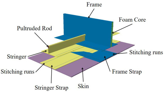
Figure 1.
Structural components of the PRSEUS concept.
In PRSEUS panels, the presence of openings not only severs fibers in the composite layer but also creates a significant high-stress concentration zone around the hole. Moreover, due to the inherent anisotropy of the composite panel, the edge area of the hole experiences peeling stress from the edge effect under the load, which substantially reduces the static and fatigue strength of the structure. This directly impacts the service life and flight safety of the PRSEUS structure. Designing an efficient opening-reinforcement strategy for PRSEUS structures to cope with specific load environments has thus become an urgent problem.
This paper focuses on typical PRSEUS panels, including those with small and mid-sized openings, which are designed and reinforced. Reasonable reinforcement schemes are proposed, and the tensile and compressive load analyses of these models are conducted. The load-bearing efficiency of each reinforcement scheme is compared and analyzed, providing a reference for the design and optimization of PRSEUS panel-opening reinforcement.
1.1. Introduction to PRSEUS Structural Elements
The panel model studied in this paper is derived from the side panel of the fuselage’s pressurized cabin. The established 3D model is depicted in Figure 2 and Figure 3. The main dimensions of the curved panel are provided in Table 1.
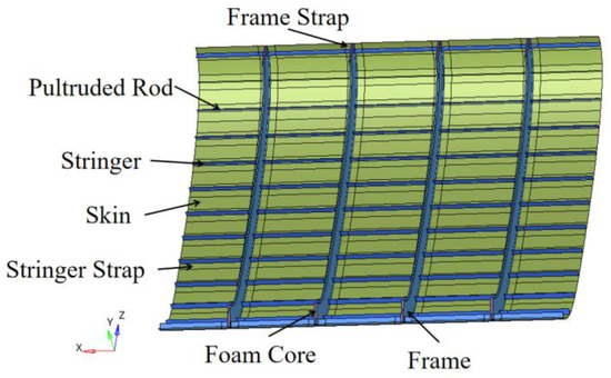
Figure 2.
Geometric model of the non-opening PRSEUS panel structure.
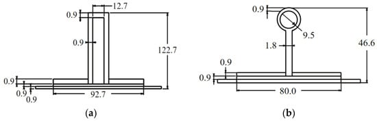
Figure 3.
Dimensions of the frame and stringer structure. (a) Dimensions of the frame structure in mm. (b) Dimensions of the stringer structure size in mm.

Table 1.
Key parameters of the PRSEUS panel.
1.2. Small-Opening Panel Design
In aircraft structural design, the incorporation of openings in load-bearing structural components is essential for several reasons, including manufacturing processes, ease of later inspection and maintenance, rational equipment installation, and accommodating the passage of pipelines. Openings are also necessary for pipes and cables required by the control system or other systems on the webs of critical components, like beams, ribs, and frames. These openings not only facilitate the normal operation of the aircraft but also reflect the complexity and precision required in structural design.
The placement of openings must consider the overall aircraft layout, usage, maintenance, and repair requirements. The small-opening design for the PRSEUS panel is based on the dimensions of aircraft passenger cabin windows. The dimension diagram for the small-opening PRSEUS panel is shown in the Figure 4, with edge lengths of 300.0 mm and 400.0 mm.
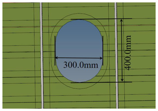
Figure 4.
The small-opening PRSEUS panel.
1.3. Mid-Sized-Opening Panel Design
The mid-sized-opening design for the PRSEUS panel is based on the dimensions of aircraft passenger cabin doors. The dimensions of the mid-sized-opening PRSEUS panel are shown in the Figure 5, with side lengths of 857.0 mm and 1437.0 mm.
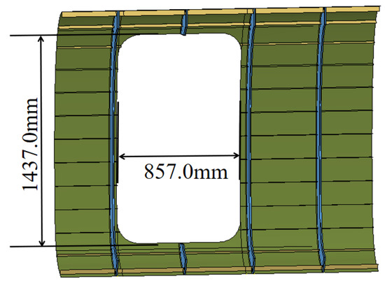
Figure 5.
The mid-sized-opening PRSEUS Panel.
2. Finite Element Model of Panel Pane
2.1. Model Material
In the PRSEUS structure, the stacks, flanges, tear straps, and skin are made of composite laminate, while the pultruded rods at the top of the stringers are composed of T800 carbon fiber and 3900-2B resin. The foam core of the frames utilizes Rohacell foam. The material properties of the pultruded rods at the stringer tops and the frame’s foam core are detailed in Table 2, and those of the composite laminates are in Table 3 [28,29].
Table 2.
Material parameters of pultruded rods and foam core of frames [28].
Table 3.
Composite laminate material parameters [29].
The layup parameters for each component are shown in Table 4. This concept comprises the skin, frame web, frame flanges, frame tear straps, stringer web, stringer flanges, and stringer tear straps; the lamina has nine plies stacked in the sequence [45, −45, 0, 0, 90, 0, 0, −45, 45]T. And, it is 1.35 mm thick. The fiber proportions are 44.4, 44.4, and 11.1 at 0°, 45°, and 90°, respectively.
Table 4.
Composite material layup parameters.
2.2. Mesh Convergence Analysis
To perform the mesh convergence analysis for the panel structure without openings, the tensile load condition of 6500 N/mm2 is selected as a representative condition for the mesh convergence assessment, considering that the tensile and compressive load conditions are all in-plane loads applied with the same load magnitude. Figure 6 shows the maximum stress values at different mesh scales, and the simulation results show that the stress maps of the PRESUS wall model at each mesh scale show similarity and the maximum stress values are all located at the same position. According to the analysis results, when the mesh size is less than or equal to 20 mm, the calculation results show a convergence trend. Therefore, this paper adopts 20 mm as the grid size for meshing the model.
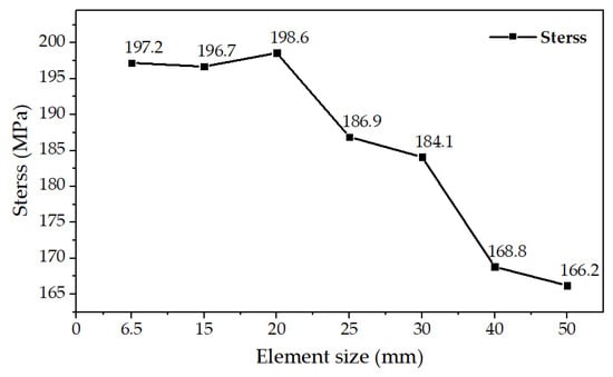
Figure 6.
Mesh convergence analysis.
2.3. Structural Meshing
In the PRSEUS structure, the stacks, flanges, tear straps, and skin are made of composite laminate, while the pultruded rods at the top of the stringers are composed of T800 carbon fiber and 3900-2B resin. The foam core of the frames utilizes Rohacell foam. In this section, Hypermesh 2021 software is used to create the element mesh. C3D8R elements are utilized for the foam core of the frame, the BAR2 elements for the stringer pultruded rods, and the S4R and S3R elements for the other composite laminates. The global mesh size is set at 20.0 mm. Mesh quality is optimized according to the standards in Table 5, and the panel mesh model is shown in Figure 7.
Table 5.
Mesh quality standards.
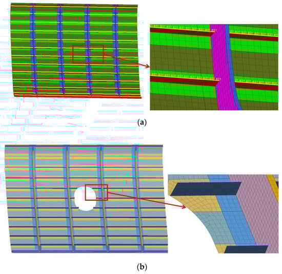
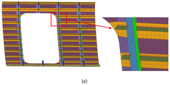
Figure 7.
PRSEUS panel mesh model. (a) Grid model of unopened panel. (b) Grid model of small-opening panel. (c) Grid model of mid-sized-opening panel.
When performing mesh generation, it is necessary to adhere to the working conditions under a quasi-static load, thus ensuring uniform mesh size distribution with differences controlled within the range of 6 to 30 mm, in order to avoid a reduction in model simulation accuracy due to significant size disparities. Particularly at the openings or edge areas of the model, a more refined mesh-generation strategy should be adopted to capture the complex stress-concentration phenomena in these regions.
Regarding the Jacobian indicator of mesh elements, it quantifies the ratio of the minimum Jacobian value to the maximum Jacobian value at the integration points within the element, serving as a key parameter to measure the degree of deviation of the element shape from its ideal (or standard) form. To ensure high-quality mesh elements, it is specifically stipulated that the Jacobian value must not be less than 0.6, serving as the lower limit for the reasonableness of the mesh shape.
In addition, the aspect ratio, as an important indicator for evaluating the length–width ratio of mesh elements, indicates that the closer its value is to 1, the closer the mesh element is to a square or equilateral shape, implying better quality. Conversely, an increase in the aspect ratio suggests that the mesh element tends to be elongated, which adversely affects the accuracy of the simulation results. Therefore, an upper limit of 5 is set for the aspect ratio to control the mesh quality within an acceptable range.
The warping factor is used to measure the degree of warping of mesh elements. If this value reaches 5.0 in software simulation, it is considered a warping error. To avoid such issues, it is necessary to ensure that the Warping Factor of all elements does not exceed 5 during mesh generation, thereby guaranteeing the smooth progress of simulation and the reliability of results.
For shell model meshes, to prevent simulation errors caused by mesh distortion, this paper specifically stipulates that the internal angles of quadrilateral shell elements should be between 40° and 135°, while the internal angles of triangular shell elements are restricted to between 40° and 120°. These angular constraints help maintain the good shape and stability of shell elements, further enhancing the overall quality of the mesh model and simulation accuracy.
2.4. Boundary Conditions
The X direction of the model aligns with the stringer direction, the Y direction points outward from the panel surface, and the Z direction coincides with the layout of the partition frame. The boundary conditions for PRSEUS panels are set based on testing conditions. One end in the stringer direction is fixed, while the other end serves as the loading end. At the loading end, translational degrees of freedom in the Z direction and rotational degrees of freedom in all directions are constrained. The model applies a uniform tensile or compressive load at the loading end.
During the model’s simulation, the large displacements or shape changes of the grid due to the rigidity of initial stresses or loads are considered, as these can directly affect the response of the structure and cause geometric nonlinear phenomena. Consequently, nonlinear finite element analysis is conducted on the pressurized cabin structure. Damping is implemented during the analysis step to prevent excessive deformation of the mesh elements and to avoid defects.
During the aircraft-type design process, the 1200 N/mm2 general load condition and the 6500 N/mm2 ultimate load condition are clearly defined. This paper examines the load performance of the small-opening wall plate under the ultimate load condition and the load performance of the mid-opening wall plate under the general load condition.
In the discussion of this paper, we have used a stress intensity criterion that consists mainly of tensile and compressive stresses in the longitudinal and transverse directions and shear stresses. Together, these stress elements form the basis of a complex stress state, which is essential for an accurate assessment of structural strength.
In order to visualize and quantify the stress concentration phenomenon and the distribution of stresses within the structure, we introduce the von Mises equivalent stress map as an analysis tool, which, as an equivalent single numerical stress, can comprehensively reflect the actual stress on the material under the multiaxial stress state, and its cloud map form effectively reveals the stress-concentration area and the change-of-stress gradient, which can be used for the optimization and design of the structure, fatigue life prediction, and safety assessment. It provides strong data support for structural design optimization, fatigue life prediction, and safety assessment.
2.5. Opening Panel Stress Analysis
Several schemes have been designed to analyze the stress distribution in the PRSEUS panels with openings, as presented in Table 6. Table 6 presents the specific structural adjustments and analyses conducted as part of a dedicated inquiry into the causes of stress concentration at openings. These adjustments, serving as particular instances within the scope of this section’s research, aim to provide an in-depth examination of stress-concentration phenomena under specific conditions. Their scope and implications are strictly confined to the current chapter of research, without any modification of the research domains or established structures of other sections within the overall paper.
Table 6.
Design factors impacting panel simulation results.
Because the ultimate load is in the same order of magnitude as the general loading condition, it is sufficient to analyze the simulation results of the open wall plate for only one loading condition. In this paper, we analyze the stress changes in a small-opening PRSEUS panel under general tensile conditions.
The stress contour plots for each scheme are displayed in Figure 8, Figure 9, Figure 10 and Figure 11. With the size and shape of the panel opening remaining constant, the primary factor influencing stress concentration in a PRSEUS panel structure under a tensile load is the fiber ply angle of the composite material of the open panel. The secondary factor is the arrangement of load-bearing structures, such as panel frames and beams. Without altering the fiber ply angle or the structural layout of the frame and beams, the maximum von Mises stress in the panel typically occurs near the opening, with the relative position of the opening remaining unchanged.
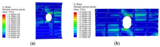
Figure 8.
The effect of symmetry in panel openings on simulation outcomes of the model. (a) Opening symmetry from side to side. (b) Opening symmetry up and down.
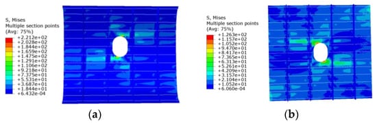
Figure 9.
The effect of panel curvature on the simulation outcomes of the model. (a) Curved small-opening PRSEUS panel. (b) Flat small-opening PRSEUS panel.
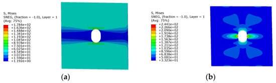
Figure 10.
The effect of composite ply orientation on simulation outcomes of the model. (a) Flat 0° ply laminate. (b) Flat 90° ply laminate.
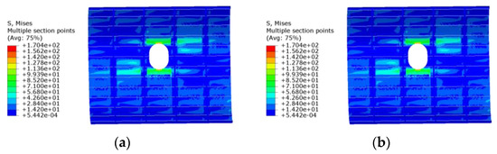
Figure 11.
The effect of composite ply orientation and panel configuration on simulation outcomes of the model. (a) Curved PRSEUS 0° ply laminate. (b) Curved PRSEUS 90° ply laminate.
In the composite material, the fiber primarily strengthens and bears the load, while the matrix supports and protects the fibers, distributing and transferring the load among them. Therefore, the direction of the fiber arrangement (i.e., the ply direction) dictates the main performance characteristics of the material. Different fiber ply directions lead to varied internal stress distributions within the material. The frame and beam structures also play a crucial role in modifying the path and direction of force transmission across the panel; thus, the structural design of these components significantly influences the stress distribution.
3. Reinforcement Design and Analysis of Typical PRSEUS Panel Structures with a Small Opening
The presence of openings in a composite panel leads to the severance of local fibers, highly decreasing the structural stiffness and strength of the area and making it more susceptible to premature failure due to stress concentration. Additionally, structural stability is a critical issue in aircraft design. During static tests, the ultimate failure of the aircraft is often triggered by a loss of local structural stability, necessitating reinforcement designs for areas around the panel openings [30,31,32,33,34,35].
3.1. Design of Reinforcement Schemes of a Typical PRSEUS Panel Structure with a Small Opening
Based on the experience of designing the opening reinforcement of DC-8, DC-10, Boeing 707, and other types of airliners, this paper carries out research on the design of small-opening reinforcement of PRSEUS panels. The mouth frame reinforcement and the frame reinforcement are proposed, which have a wide application base in the aerospace field and have been proven to have good reinforcement effects. In addition, the boss reinforcement is designed to further improve the reinforcement efficiency and structural integrity. In order to comprehensively evaluate the effectiveness of the various reinforcement methods, we combine the above reinforcement methods and finally propose five different reinforcement schemes with a view to provide diversified choices and optimized solutions to meet different aircraft structural and design requirements. Reinforcement schemes are shown in the Table 7.
Table 7.
Small-opening reinforcement schemes for PRSEUS panels.
Scheme A utilizes a 5.0 mm thick mouth frame as reinforcement, covering an area 0.2 times the width of the opening, designed as a circular ring. Scheme B employs ring boss reinforcement, creating a 10.0 mm thick frame with a height of 13.0 mm around the opening. Scheme C combines mouth and ring boss reinforcements, which are 3.4 mm thick. This scheme reduces the thickness of the component by 1.6 mm compared to Scheme A, resulting in a reduction in weight. Scheme D involves arranging 3.4 mm thick stiffeners around the opening, with the stiffeners standing 35.0 mm high and linking with the surrounding frames, while adding a circular 2.6 mm thick mouth frame reinforcement. Scheme E reduce the width of the reinforcement structure on the basis of Scheme C, utilizing a 1.2 mm thick mouth frame and a 5.0 mm thick ring boss reinforcement. Reinforcement structures are made of composite materials, and the fiber proportions are 40–47, 40–47, and 7–15 at 0°, 45°, and 90°, respectively. The lamina is 2.0 mm thick. The specific 3D model diagram of Scheme A–D is shown in Figure 12.
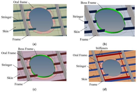
Figure 12.
Illustrations of opening reinforcement configurations for different PRSEUS panel schemes. (a) Scheme A mouth reinforcement. (b) Scheme B boss reinforcement. (c) Scheme C and Scheme E mouth and boss reinforcement. (d) Scheme D frame and mouth reinforcement.
The structural weight changes of the PRSEUS panel without an opening and the small-opening panels after reinforcement are compared and analyzed, as depicted in Figure 13. Scheme B, Scheme C, and Scheme E show a smaller weight increase, while Scheme D results in the most significant weight gain. The reinforcing structure for the small opening has a minimal impact on the weight change of the panel structure.
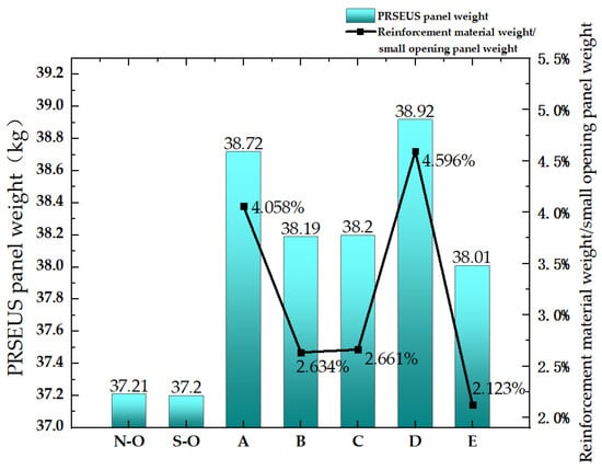
Figure 13.
Weight variation of PRSEUS panels. Note: N-O denotes a non-opening PRSEUS panel, S-O denotes a small-opening PRSEUS panel, and A–E denotes small-opening-reinforcement Scheme A–E.
3.2. Tensile Load Analysis of PRSEUS Panels and Reinforced Structures with a Small Opening
The entire simulation test process is conducted under static loading conditions. A tensile load of 6500 N/mm2 is applied at the loading end, taking into account the influence of geometric nonlinear factors. Damping is applied during the analysis step to prevent the mesh elements from deforming too rapidly and to avoid defects.
The stress cloud diagram indicates that the stress of the small-opening-reinforcement schemes is concentrated in the opening reinforcement and the skin and it spreads to the surrounding area; the in-plane shear stress is concentrated around the opening and the beginning of the spacer frame stopping zone, and the stress of the panel is significantly reduced after reinforcement, such as in the example of Scheme A.
Stress and strain cloud diagrams are shown in Figure 14 and Figure 15. The frame in the structure changes the transfer of load force, making the structure of the stress distribution more uniform; due to the frame, the stiffness is too great, resulting in the shear phenomenon. The frame at the shear stress is higher, so the panel produces compressive stress. Due to the design of the openings, the concentration of stress in the PRSEUS panel appears in the vicinity of the openings. The strain cloud is similar to the stress cloud, and it also proves the reliability of the simulation results.
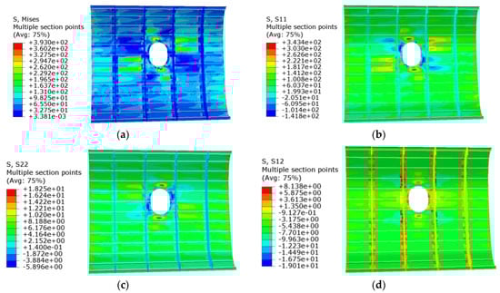
Figure 14.
Stress cloud of Scheme A’s structure under tensile loading conditions. (a) von Mises stress. (b) Longitudinal stress. (c) Transverse stress. (d) In-plane shear stress. Notes: S11 is the structural longitudinal stress cloud, S22 is the structural transverse stress cloud, and S12 is the structural in-plane shear stress cloud.
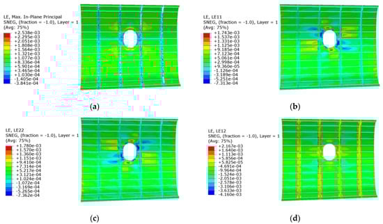
Figure 15.
Scheme A strain map under tensile loading conditions. (a) Strain. (b) Longitudinal strain. (c) Transverse strain. (d) In-plane shear strain. Notes: L11 is the structural longitudinal strain cloud, L22 is the structural transverse strain cloud, and L12 is the structural in-plane shear strain cloud.
The stress of the non-opening PRSEUS panel, the small-opening panel, and the reinforced panels under tensile load conditions are compared and analyzed, as shown in Table 8 and Figure 16. The tension reinforcement efficiency (the reinforcement efficiency under tensile loading conditions) of each scheme is displayed in Table 9 and Figure 17.
Table 8.
Stress variation of the PRSEUS panel under tensile load.
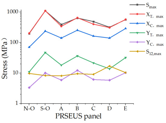
Figure 16.
Stress variation of PRSEUS panels under tensile load.
Table 9.
Tensile reinforcement efficiency of PRSEUS panels with small-opening reinforcements.
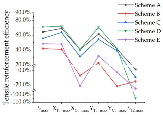
Figure 17.
Tensile reinforcement efficiency of small-opening reinforced PRSEUS panels.
The ratio of the maximum stress reduction value of the reinforced panel to the maximum stress value of the unreinforced panel is referred to as the reinforcement efficiency, and it can be expressed by the formula:
where denotes the reinforcement efficiency, represents the maximum stress value of the unreinforced panel, and indicates the maximum stress value of the reinforced panel.
It is evident from the chart that the longitudinal direction of the fiber is the main bearing direction, and the panel experiences less shear in-panel. The local stress increases in the small-opening PRSEUS panel, and the maximum von Mises stress increases by a factor of 4.57 compared to the non-opening panel. The maximum von Mises stress of the reinforced panel increases by factors ranging from 0.58 to 2.24 compared to the non-opening panel, while the stress of the reinforced panel meets the material strength requirements.
Compared to the small-opening PRSEUS panel without reinforcement, the reinforcement efficiency of Scheme A is 64.53%, that of Scheme B is 42.07%, that of Scheme C is 55.68%, that of Scheme D is 71.05%, and that of Scheme E is 48.64%. The longitudinal loading direction is the primary load-bearing direction of the panel, and all five reinforcement schemes improve the longitudinal tensile load capacity. However, all five schemes exhibit poor reinforcement effects on the shear load capacity. The maximum longitudinal compressive stress values of Scheme B and Scheme E are higher than that of the non-opening panel, indicating an unreasonable reinforcement. Scheme D has the highest reinforcement efficiency, followed by Scheme A, with Scheme B having the lowest efficiency.
The displacement changes of the non-opening PRSEUS panel, the small-opening panel, and the reinforced panels under tensile load conditions are compared and analyzed, as shown in Table 10 and Figure 18. The displacement-reduction efficiency of the reinforcement scheme is shown in Table 11 and Figure 19.
Table 10.
Displacement variation of PRSEUS panels under tensile load.
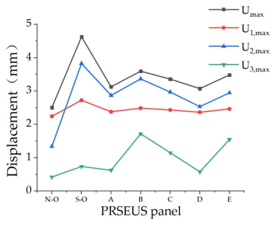
Figure 18.
Displacement variation of PRSEUS panels under tensile load.
Table 11.
Displacement-reduction efficiency of PRSEUS panels with small-opening reinforcements under tensile conditions.
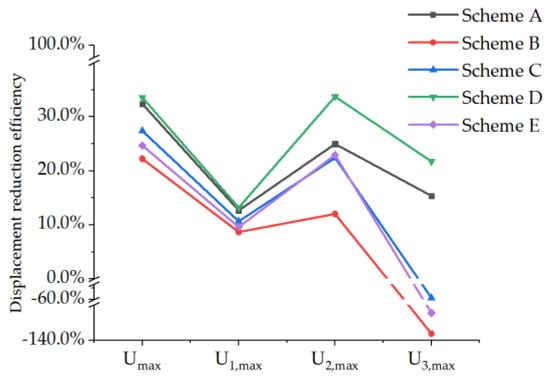
Figure 19.
Tensile displacement-reduction efficiency of small-opening reinforced PRSEUS panels.
The ratio of the maximum displacement reduction value of the reinforced panel to the maximum displacement value of the unreinforced panel is called the displacement-reduction efficiency, and it can be formulated into the function
where denotes the displacement-reduction efficiency, denotes the maximum displacement value of the unreinforced panel, and denotes the maximum displacement value of the reinforced panel.
The PRSEUS panel exhibits a tendency to displace in the tensile direction. The maximum principal displacement for the non-opening PRSEUS panel is 2.505 mm. Displacement measurements along the X, Y, and Z directions are 2.244 mm, 1.341 mm, and 0.426 mm, respectively. When the PRSEUS panel is designed with a small opening, the maximum principal displacement increases by 85.0%; displacement in the X direction increases by 22%; in the Y direction, it increases by 185.0%; and in the Z direction, it increases by 74.0%.
Compared with the small-opening PRSEUS panel without reinforcement, the displacement in reinforcement schemes A–E is reduced. The displacement-reduction efficiency in the X and Y directions for Scheme D is the highest at 13.21% and 33.75%, respectively. The displacement-reduction efficiency in the Z direction for Schemes A and D is significantly higher than that for the other schemes at 15.38% and 21.73%, respectively. Schemes B and C exhibit increased displacement along the Z direction, indicating ineffective reinforcement. Scheme D demonstrated the highest displacement-reduction efficiency, followed by Scheme A, with Scheme B showing the lowest efficiency.
3.3. Compressive Load Analysis of PRSEUS Panels and Reinforced Structures with a Small Opening
The entire simulation test process is conducted under static loading conditions. A compressive load of 6500 N/mm2 is applied at the loading end, considering the influence of geometric nonlinear factors. Damping is used to prevent the mesh elements from deforming too rapidly and to avoid defects.
The stress cloud show that the stresses in the small opening reinforcement scheme are concentrated in the area of the opening reinforcement; the in-face shear stresses are concentrated around the frame and in the opening area of the panel. As in the case of Scheme A, the stresses in the panels are significantly reduced by the reinforcement. Stress and strain cloud diagrams are shown in Figure 20 and Figure 21. In the case of an overall structure subjected to pressure loads, significant changes in the local stress state are triggered by the adjustment of the specific layout and construction details of the structural elements, as well as the redistribution and optimization of the force transfer paths within the structure. The frame in the structure changes the transfer of load force, making the structure of the stress distribution more uniform; and, due to the frame stiffness being too high, the shear phenomenon occurs. The frame at the shear stress is higher, so the panel produces tensile stress due to the design of the openings, resulting in the concentration of stress in the PRSEUS panel that appears in the vicinity of the openings. The strain cloud is similar to the stress cloud, and it also proves the reliability of the simulation results.
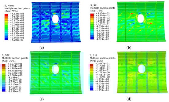
Figure 20.
Stress cloud of Scheme A’s structure under compressive loading conditions. (a) von Mises stress. (b) Longitudinal stress. (c) Transverse stress. (d) In-plane shear stress. Notes: S11 is the structural longitudinal stress cloud, S22 is the structural transverse stress cloud, and S12 is the structural in-plane shear stress cloud.
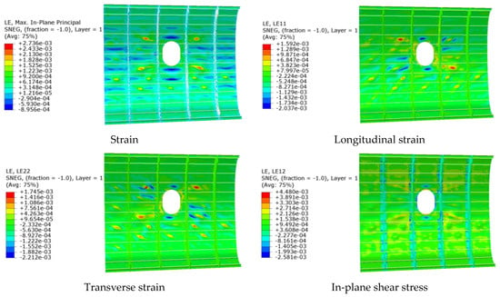
Figure 21.
Scheme A strain map under compressive loading conditions. Notes: L11 is the structural longitudinal strain cloud, L22 is the structural transverse strain cloud, and L12 is the structural in-plane shear strain cloud.
The stress of the non-opening PRSEUS panel, the small-opening panel, and the reinforced panels under compressive load conditions are compared and analyzed, as shown in Table 12 and Figure 22. The compressive reinforcement efficiency of each scheme is displayed in Table 13 and Figure 23.
Table 12.
Stress variation of PRSEUS panels under compressive load.
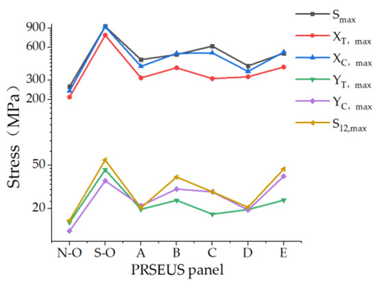
Figure 22.
Stress variation of PRSEUS panels under compressive load.
Table 13.
Compressive reinforcement efficiency of PRSEUS panels with small-opening reinforcements.
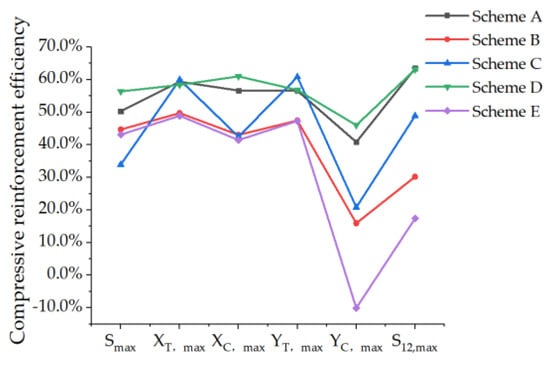
Figure 23.
Compressive reinforcement efficiency of small-opening reinforced PRSEUS panels.
The fiber’s longitudinal direction served as the main bearing direction, and the panel experienced less shear in the facet. The opening in the PRSEUS panel increases the local stress, with the maximum von Mises stress being 2.55 times higher than that of the non-opening panel. The maximum stress of the reinforced panel ranged from 0.55 to 1.34 times higher than that of the non-opening panel, and the stress of the reinforced panel met the material strength requirements.
Compared to the small-opening PRSEUS panel without reinforcement, the reinforcement efficiency of Scheme A’s reinforced panel is 50.34%, Scheme B’s is 44.70%, Scheme C’s is 33.97%, Scheme D’s is 56.41%, and Scheme E’s is 43.15%. The longitudinal tensile load of all five schemes is improved, and the efficiency of the longitudinal tensile stress reinforcement of Scheme C is the highest at 59.99%. Scheme D has the highest longitudinal compressive stress reinforcement efficiency at 61.03%. Scheme D also has the highest overall reinforcement efficiency, followed by Scheme A, with Scheme C having the lowest.
The displacement changes of the non-opening PRSEUS panel, the small-opening panel, and the reinforced panels under compressive load conditions are compared and analyzed, as shown in Table 14 and Figure 24. The displacement-reduction efficiency of each scheme is detailed in Table 15 and Figure 25.
Table 14.
Displacement variation of PRSEUS panels under compressive load.
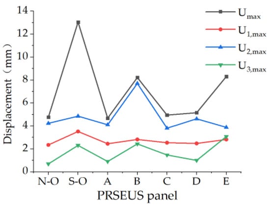
Figure 24.
Displacement variation of PRSEUS panels under compressive load.
Table 15.
Displacement-reduction efficiency of PRSEUS panels with small-opening reinforcements under compressive conditions.
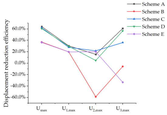
Figure 25.
Compressive displacement-reduction efficiency of small-opening reinforced PRSEUS panels.
PRSEUS panels exhibited a tendency to deform in the X and Y directions. The maximum principal displacement for the non-opening PRSEUS panel is 4.766 mm. Displacement measurements along the X, Y, and Z directions are 2.350 mm, 4.231 mm, and 0.697 mm, respectively. When the PRSEUS panel includes a small opening, the maximum principal displacement increases by 17.38 times, the displacement in the X direction increases by 0.50 times, the displacement in the Y direction increases by 0.15 times, and the displacement in the Z direction increases by 2.31 times.
Compared with the small-opening PRSEUS panel without reinforcement, the displacement is reduced in Schemes A–E. The displacement-reduction efficiency in the X direction is highest for Scheme A at 30.36%. In the Y direction, Scheme C shows the greatest efficiency, while Scheme B experiences an increase in maximum displacement by 58.65%. The displacement-reduction efficiency in the Z direction for Schemes A and D is significantly higher than that for the other schemes at 60.74% and 56.58%, respectively. Scheme A demonstrates the highest displacement-reduction efficiency, followed by Scheme C, with Scheme E showing the lowest efficiency.
3.4. Load-Bearing Efficiency Analysis of Reinforced PRSEUS Panels with a Small Opening
In this section, the load-bearing efficiency of reinforcement schemes for panels with a small opening is compared and analyzed. The load-bearing efficiency ratio is calculated as follows:
where denotes the load-bearing efficiency, represents the maximum stress value of the unreinforced panel, and is the maximum stress value of the reinforced panel (unit: MPa). is the weight of the reinforced panel structure, and is the weight of the unreinforced, open-panel structure (unit: kg). The load-bearing efficiency of small-opening reinforced PRSEUS panels are shown in the Figure 26.
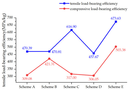
Figure 26.
Load-bearing efficiency of reinforced panels under tensile and compressive loads.
It is observed that the load-bearing efficiency for reinforced panels with a small opening is higher under the tensile load than under the compressive load. Scheme E exhibits the highest load-bearing efficiency under both tensile and compressive load conditions, at 673.63 MPa/kg and 503.38 MPa/kg, respectively.
4. Reinforcement Design and Analysis of Typical PRSEUS Panel Structure with a Mid-Sized Opening
Generally, besides the skin, a mid-sized opening often necessitates cutting several stringers in the body’s structure to handle normal stress. Passenger boarding gates are a typical example. Longitudinal and transverse profiles should be carefully arranged in a grid pattern around the opening, incorporating significantly reinforced ring frames to provide adequate support and stability [36,37,38]. Additionally, the outer longitudinal and transverse profiles should use the original long stringers and frame edge strips as much as possible to minimize structural changes and costs, yet they must be suitably strengthened to ensure structural safety. To concentrate the axial force from the cut stringers on one side of the opening (or redistribute it to one side), the reinforcing profiles above and below the opening should extend an appropriate section.
Beyond the layout of longitudinal and transverse profiles, a reinforcing plate can be added around the opening to integrate closely with the frame strips and stringers at the perimeter, thus forming a robust enclosing frame structure. When transferring the axial forces from the cut stringers, they can be effectively concentrated into the reinforced profiles above and below the opening through the shearing action of the skin and the backing plate. The backing plate, made from a thick plate, acts as a reinforcing measure to handle both shear and axial forces at the opening.
4.1. Design of Reinforcement Scheme of Typical PRSEUS Panel Structures with a Mid-Sized Opening
With reference to modern airliners in the aerospace sector, we adopted three reinforcement methods for the mid-sized-opening PRSEUS panel. Scheme I utilizes a grid reinforcement approach with transverse stiffeners with a height of 120.0 mm and longitudinal stiffeners measuring 35.0 mm in height. Scheme II incorporates reinforcement pads and stiffeners alongside the grid reinforcement, with pads averaging 80.0 mm in width and 2.7 mm in thickness, while the stiffeners maintain a height of 35.0 mm and a thickness of 2.7 mm. Scheme III utilizes cross-shaped reinforcement and increases the thickness of the frames and stringers in the original panel structure around the openings. The reinforced frames are 1.8 mm thick, and the stringers are 3.6 mm thick. Additionally, the dimensions of the T-shaped stiffeners are modified, with T-stiffener parameters being b = 120.0 mm, h = 55.0 mm, tf = 1.4 mm, and tw = 2.7 mm. The fiber proportions are 40–47, 40–47, and 7–15 at 0°, 45°, and 90°, respectively. And, the lamina is 1.5 mm thick. The specific schemes are outlined in Table 16 and illustrated in Figure 27.
Table 16.
Open-hole reinforcement scheme for PRSEUS panels.
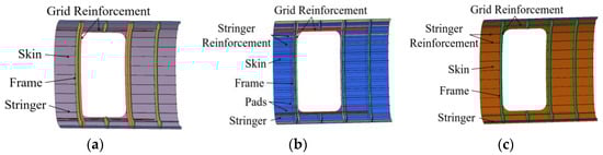
Figure 27.
Diagram of PRSEUS panels with medium-opening reinforcements. (a) Scheme I opening reinforcement diagram. (b) Scheme II opening reinforcement diagram. (c) Scheme III opening reinforcement diagram.
We compared and analyzed the structural weight changes of the non-opening PRSEUS panel and the mid-sized-opening panel after reinforcement, as shown in Figure 28. The weight ratio of the three schemes is approximately 2.1:1, with the weight of Scheme II slightly higher than that of Schemes I and III.
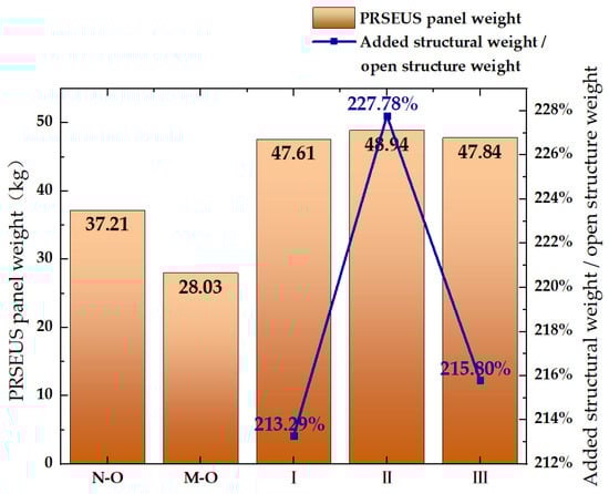
Figure 28.
Weight variation of PRSEUS panels. Note: N-O denotes non-opening PRSEUS panel, M-O indicates mid-sized-opening PRSEUS panel, and I–III represents mid-sized-opening reinforcement Scheme I–III.
4.2. Tensile Load Analysis of Typical PRSEUS Panels and Reinforced Structures with a Mid-Sized Opening
The entire simulation test process is conducted in a static loading state. A 1200 N/mm2 tensile load is applied at the loading end, and the influence of geometric nonlinear factors is considered. Damping is applied during the analysis step to prevent the mesh elements from deforming too quickly and to avoid defects. The stress of the mid-sized-opening PRSEUS panel and the reinforced panel under a tensile load is compared in Table 17 and Figure 29. The tensile reinforcement efficiency of each scheme is presented in Table 18 and Figure 30.
Table 17.
PRSEUS panel tensile load stress variation.
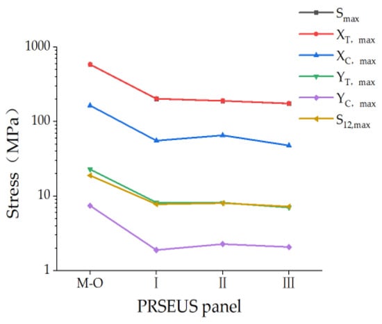
Figure 29.
Stress variation of PRSEUS panels under tensile load.
Table 18.
Tensile reinforcement efficiency of open-hole reinforced panels in PRSEUS.
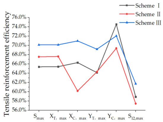
Figure 30.
Tensile reinforcement efficiency of mid-sized-opening reinforced PRSEUS panels.
As indicated in the charts, the stress in the mid-sized-opening panel increases, with the maximum von Mises stress rising by 15.22 times compared to the non-opening PRSEUS panel. The maximum von Mises stress of the reinforced panel is 3.85–4.59 times higher than that of the non-opening panel, and the stress of the reinforced panel meets the material strength requirements.
Compared to the mid-sized-opening PRSEUS panel without reinforcement, all three reinforcement schemes improve the tensile load capacity. The reinforcement efficiencies of all three schemes exceed 50%, with Scheme I achieving a reinforcement efficiency of 65.38%, Scheme II achieving 67.54%, and Scheme III achieving 70.12%. The principal load-bearing direction of the panel is along the fiber’s longitudinal axis, with minimal stress observed in the transverse and shear components. Scheme III exhibits the highest reinforcement efficiency, while Scheme I shows the lowest.
The displacement change of the reinforced PRSEUS panel under tensile load conditions is compared and analyzed in Table 19 and Figure 31, and the displacement-reduction efficiency of the reinforced scheme is shown in Table 20 and Figure 32.
Table 19.
Displacement variation of PRSEUS panels under stress load.
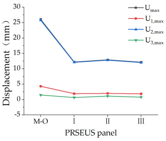
Figure 31.
Displacement variation of PRSEUS panels under tensile load.
Table 20.
Displacement-reduction efficiency of PRSEUS panels with mid-sized-opening reinforcements under stress conditions.
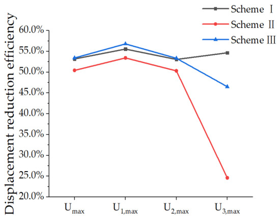
Figure 32.
Tensile displacement-reduction efficiency of mid-sized-opening reinforced PRSEUS panels.
The non-opening PRSEUS panel shows displacement trends in the X and Y directions, with the maximum principal displacement being 0.500 mm. The displacement along the X direction is 0.416 mm; along the Y direction, it is 0.307 mm. The displacement trend along the Z direction is minimal at 0.084 mm. When the PRSEUS panel is designed with a mid-sized opening, the maximum principal displacement increases by 51.16 times, the maximum displacement in the X direction increases by 9.40 times, the maximum displacement in the Y direction increases by 82.97 times, and the maximum displacement in the Z direction increases by 16.67 times.
Compared to the unreinforced mid-sized-opening PRSEUS panel, the three schemes significantly affect the panel’s displacement, with displacement-reduction efficiencies above 50%. The displacement-reduction efficiency of Scheme III in the X and Y directions is the highest at 56.79% and 53.34%, respectively. The reinforcement efficiency of Scheme I in the Z direction is the highest at 54.65%. Scheme I and Scheme III have a more significant effect on displacement reduction than Scheme II, with Scheme III having the highest displacement-reduction efficiency of 53.41%.
4.3. Compressive Load Analysis of Typical PRSEUS Panels and Reinforced Structures with a Mid-Sized Opening
The entire simulation test process is conducted under static loading conditions. A 1200 N/mm2 compressive load is applied at the loading end, and the influence of geometric nonlinear factors is considered. Damping is introduced during the analysis step to prevent the mesh elements from deforming too rapidly and to avoid defects. The stress analysis for the mid-sized-opening PRSEUS panel and the reinforced panel under a compressive load is presented in Table 21 and Figure 33, with the compressive reinforcement efficiency of each scheme detailed in Table 22 and Figure 34.
Table 21.
PRSEUS panel compressive load stress variation.
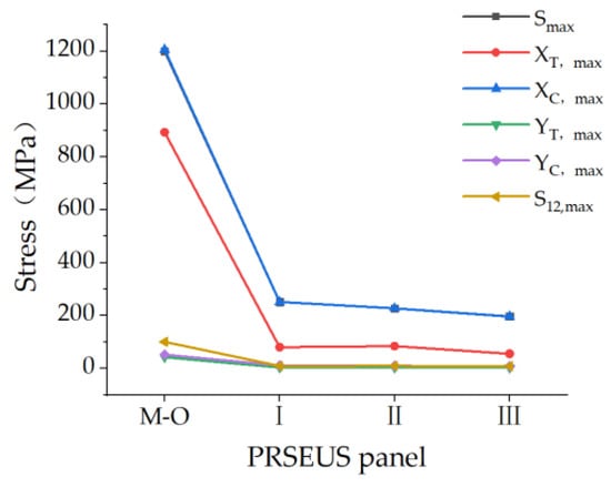
Figure 33.
Stress variation of PRSEUS panels under compressive load.
Table 22.
Tensile reinforcement efficiency of open-hole reinforced panels in PRSEUS.
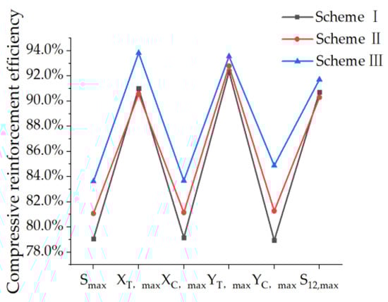
Figure 34.
Compressive reinforcement efficiency of mid-sized-opening reinforced PRSEUS panels.
The stress in the mid-sized-opening panel increases significantly, with the maximum von Mises stress rising by 32.45 times compared to the non-opening PRSEUS panel. The maximum von Mises stress of the reinforced panel is 4.48–6.00 times higher than that of the non-opening panel without reinforcement, and the stress levels of the reinforced panel meet the material strength requirements.
Compared to the unreinforced mid-sized-opening PRSEUS panel, the compressive reinforcement efficiency of the three schemes is approximately 80%, with Scheme I achieving 79.07%, Scheme II achieving 81.08%, and Scheme III achieving 83.63%. Scheme III exhibits the highest reinforcement efficiency, while Scheme I shows the lowest.
The displacement changes of the mid-sized-opening PRSEUS panel and the reinforced panel under a compressive load are compared and analyzed, as shown in Table 23 and Figure 35. The displacement-reduction efficiency of the panels in each scheme is displayed in Table 24 and Figure 36.
Table 23.
Displacement variation of PRSEUS panels under compressive load.
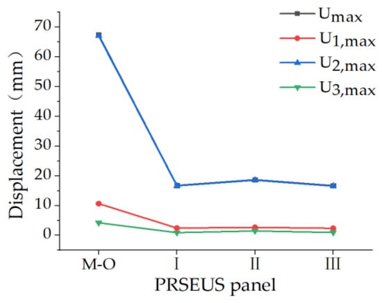
Figure 35.
Displacement variation of PRSEUS panels under compressive load.
Table 24.
Displacement-reduction efficiency of PRSEUS panels with mid-sized-opening reinforcements under compressive conditions.
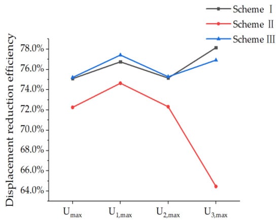
Figure 36.
Compressive displacement-reduction efficiency of mid-sized-opening reinforced PRSEUS panels.
The non-opening PRSEUS panel shows displacement trends in the X and Y directions, with the maximum principal displacement being 0.529 mm. The displacement along the X direction is 0.418 mm, and along the Y direction, it is 0.349 mm. The displacement trend along the Z direction is minimal at 0.086 mm. In the mid-sized-opening PRSEUS panel, the maximum principal displacement increases by 126.35 times, the maximum displacement in the X direction increases by 24.50 times, the maximal displacement in the Y direction increases by 191.09 times, and the maximal displacement in the Z direction increases by 48.17 times.
Compared to the unreinforced mid-sized-opening PRSEUS panel, the displacement-reinforcing effect of the three schemes is significant, with the displacement-reduction efficiency exceeding 70%. Scheme III offers the highest displacement-reduction efficiency in the X and Y directions at 77.42% and 75.28%, respectively. The reinforcement efficiency of Scheme I along the Z direction is the highest at 78.15%. Scheme III has the highest displacement-reduction efficiency at 75.21%.
4.4. Load-Bearing Efficiency Analysis of Reinforced Structure of PRSEUS Panels with a Mid-Sized Opening
In this section, the load-bearing efficiency of the reinforced scheme for the mid-sized-opening panel is compared and analyzed, as shown in Figure 37. From the diagram, it is evident that the load-bearing efficiency of the reinforced panel under a tensile load is higher than under a compressive load. Scheme III exhibits the highest load-bearing efficiency under both tensile and compressive load conditions at 20.74 MPa/kg and 50.66 MPa/kg, respectively.
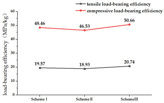
Figure 37.
Load-bearing efficiency of reinforced panels under tensile and compressive loading conditions.
5. Summary
In this paper, we design both small- and mid-sized openings for the PRSEUS panel and propose a variety of reinforcement schemes based on the principle of structural opening reinforcement. We conduct tensile and compressive load simulation analyses to evaluate the bearing capacity of the reinforcement panel. Here is a summary.
(1) We design the typical PRSEUS panel structure and incorporate both small- and mid-sized openings.
(2) Based on the typical PRSEUS panel structure with a small opening, we propose four reinforcement schemes, such as mouth frames and bosses. We compare and analyze the impact of a small opening on the bearing capacity and efficiency of the PRSEUS panel. Under a tensile load, the maximum von Mises stress of the small-opening PRSEUS panel increases by 4.57 times, and the maximum principal displacement increases by 0.85 times compared to the non-opening panel. Under a compressive load, these values increase by 2.54 times and 1.74 times, respectively. After reinforcement, the panel’s efficiency significantly improves, exceeding 30%, with Scheme D showing the greatest strength increase and Scheme A the largest displacement reduction. The load-bearing efficiency of the reinforced panel is greater for tensile loads than for compressive loads. Scheme E exhibits the highest load-bearing efficiency under both tensile and compressive load conditions at 673.63 MPa/kg and 503.38 MPa/kg, respectively.
(3) For the typical PRSEUS panel structure with a mid-sized opening, we propose three reinforcing schemes. We analyze the impact of a mid-sized opening on the bearing capacity and the efficiency of these schemes. Under a uniaxial tensile load, the maximum von Mises stress and displacement of the mid-sized-opening PRSEUS panel increase by 15.22 times and 51.16 times, respectively, compared to the non-opening panel. Under uniaxial compressive load, these increases are 32.45 times and 126.35 times, respectively. Post-reinforcement, the bearing capacity of the mid-sized-opening PRSEUS panel is notably enhanced, with the reinforcement efficiency of all three schemes exceeding 50%. Under the same load value, the load-bearing efficiency of the reinforced structure under a tensile load is less than that under a compressive load. Scheme III exhibits the highest load-bearing efficiency, with 20.74 MPa/kg under a tensile load and 50.66 MPa/kg under a compressive load. The weight of the reinforced material more than doubles the weight lost due to the opening, allowing for subsequent increases in the weight of the reinforced structure to meet strength and stiffness requirements.
(4) Through comparative analysis of Von Mises stress distribution and load-bearing capacity under different configurations, this paper delves into the impact mechanism of opening size and steel bar type on the overall performance of PRSEUS panels, providing valuable insights. It is found that the opening reinforcement strategy designed in this paper effectively mitigates the stress concentration phenomenon in the opening region, provides an innovative solution for panel reinforcement, and greatly contributes to the advancement of lightweight and high-strength aerospace structural design.
In order to meet the reinforcement requirements of PRSEUS panels with small openings, the use of boss reinforcement significantly improves the load-bearing efficiency of the panel under compressive loading conditions. The addition of a mouth reinforcement enhances the performance of the panel under tensile loading conditions. Although the frame reinforcement is outstanding in terms of tensile and compressive reinforcement efficiency, its relatively high structural weight is not conducive to further applications in aerospace structural design. The use of frame-reinforcing structures can be considered to reduce structural stresses in specific situations.
For the reinforcement of the mid-opening PRSEUS panels, the cross-shaped reinforcement strategy shows the highest load-bearing efficiency under both tensile and compressive loading conditions, which fully demonstrates the significant advantages of this solution over other reinforcement methods. Therefore, it is recommended to give priority to this reinforcement scheme in the design of subsequent aircraft structures.
Author Contributions
Conceptualization, Y.Z.; methodology, Y.Z. and T.Z.; software, T.Z., J.Z. and B.C.; validation, T.Z.; formal analysis, T.Z., J.Z. and B.C.; investigation, T.Z. and J.Z.; resources, J.Z., B.C. and F.C.; data curation, F.C.; writing—original draft preparation, T.Z.; writing—review and editing, Y.Z.; visualization, T.Z.; supervision, Y.Z.; project administration, Y.Z. All authors have read and agreed to the published version of the manuscript.
Funding
This research was funded by the National Natural Science Foundation of China (Grant No. 11972301) and the Fundamental Research Funds for the Central Universities of China (Grant No. G2019KY05203).
Data Availability Statement
The data presented in this study are available on request from the corresponding author. The data are not publicly available due to this paper include ongoing and future research directions. We are unable to disclose all of the underlying data at this time until the next phase of research is completed.
Conflicts of Interest
The authors declare no conflicts of interest.
References
- Berger, R. Sustainable Aviation Fuels: The Best Solution to Large Sustainable Aircraft; Roland Berger: Munich, Germany, 2020. [Google Scholar]
- Ramon, E.; Sguazzo, C.; Moreira, P.M.G.P. A review of recent research on bio-based epoxy systems for engineering applications and potentialities in the aviation sector. Aerospace 2018, 5, 110. [Google Scholar] [CrossRef]
- Beck, A.J.; Hodzic, A.; Soutis, C.; Wilson, C.W. Influence of Implementation of Composite Materials in Civil Aircraft Industry on reduction of Environmental Pollution and Greenhouse Effect. IOP Conf. Ser. Mater. Sci. Eng. 2011, 26, 012015. [Google Scholar] [CrossRef]
- Beaumont, P.W.R. The structural integrity of composite materials and long-life implementation of composite structures. Appl. Compos. Mater. 2020, 27, 449–478. [Google Scholar] [CrossRef]
- Lee, J.; Gharghabi, P.; Boushab, D.; Ricks, T.M.; Lacy, T.E., Jr.; Pittman, C.U., Jr.; Mazzola, M.S.; Velicki, A. Artificial lightning strike tests on PRSEUS panels. Compos. Part B Eng. 2018, 154, 467–477. [Google Scholar] [CrossRef]
- Linton, K.A.; Velicki, A.; Hoffman, K.; Thrash, P.; Pickell, R.; Turley, R. PRSEUS Panel Fabrication Final Report; NASA/CR-2014-218149; NASA Technical Reports Server: Washington, DC, USA, 2014. Available online: http://ntrs.nasa.gov/search.jsp?R=20140006175 (accessed on 1 August 2024).
- Lanzi, L.; Bisagni, C. Post-Buckling experimental tests and numerical analyses on composite stiffened panels. In Proceedings of the 44th AIAA/ASME/ASCE/AHS/ASC Structures, Structural Dynamics, and Materials Conference, Norfolk, VA, USA, 7–10 April 2003; p. 1795. [Google Scholar]
- Velicki, A.; Thrash, P. Advanced structural concept development using stitched composites. In Proceedings of the 49th AIAA/ASME/ASCE/AHS/ASC Structures, Structural Dynamics, and Materials Conference, Schaumburg, IL, USA, 7–10 April 2008; p. 2329. [Google Scholar]
- Velicki, A.; Yovanof, N.; Baraja, J.; Linton, K.; Li, V.; Hawley, A.; Thrash, P.; DeCoux, S.; Pickell, R. Damage Arresting Composites for Shaped Vehicles-Phase II Final Report; National Aeronautics and Space Administration Langley Research Center: Hampton, VA, USA, 2011. [Google Scholar]
- Velicki, A.; Jegley, D. PRSEUS development for the hybrid wing body aircraft. In Proceedings of the AIAA Centennial of Naval Aviation Forum “100 Years of Achievement and Progress”, Virginia Beach, VA, USA, 21–22 September 2011; p. 7025. [Google Scholar]
- Ettoumi, S.; Zhang, Y.; Cui, B.; Zhou, J. Failure Initiation analysis of a PRSEUS BWB wing subjected to structural damage. Aerospace 2023, 10, 341. [Google Scholar] [CrossRef]
- Jain, L.K.; Mai, Y.W. Mode I delamination toughness of laminated composites with through-thickness reinforcement. Appl. Compos. Mater. 1994, 1, 1–17. [Google Scholar] [CrossRef]
- Dransfield, K.A.; Jain, L.K.; Mai, Y.W. On the effects of stitching in CFRPs—I. Mode I delamination toughness. Compos. Sci. Technol. 1998, 58, 815–827. [Google Scholar] [CrossRef]
- Bergan, A.; Bakuckas, J., Jr.; Awerbuch, J.; Tan, T.-M. Assessment of damage containment features of a full-scale PRSEUS fuselage panel. Compos. Struct. 2014, 113, 174–185. [Google Scholar] [CrossRef]
- Lovejoy, A.; Rouse, M.; Linton, K.; Li, V.P. Pressure testing of a minimum gauge PRSEUS panel. In Proceedings of the 52nd AIAA/ASME/ASCE/AHS/ASC Structures, Structural Dynamics and Materials Conference, Denver, CO, USA, 4–7 April 2011; p. 1813. [Google Scholar]
- Yovanof, N.; Lovejoy, A.E.; Baraja, J.; Gould, K. Design, analysis and testing of a PRSEUS pressure cube to investigate assembly joints. In Proceedings of the 2012 Aircraft Airworthiness and Sustainment Conference, Baltimore, MD, USA, 2–5 April 2012. NF1676L-13922. [Google Scholar]
- Li, V.; Velicki, A. Advanced PRSEUS structural concept design and optimization. In Proceedings of the 12th AIAA/ISSMO Multidisciplinary Analysis and Optimization Conference, Victoria, BC, Canada, 10–12 September 2008; p. 5840. [Google Scholar]
- Yovanof, N.; Velicki, A.; Li, V. Advanced structural stability analysis of a non-circular, BWB-shaped vehicle. In Proceedings of the 50th AIAA/ASME/ASCE/AHS/ASC Structures, Structural Dynamics, and Materials Conference, Palm Springs, CA, USA, 4–7 May 2009. [Google Scholar]
- Horton, B.; Song, Y.; Bayandor, J. Numerical investigation of stringer-frame intersections for stitched aerospace structures. In Proceedings of the 2018 AIAA/ASCE/AHS/ASC Structures, Structural Dynamics, and Materials Conference, Kissimmee, KL, USA, 8–12 January 2018; p. 0230. [Google Scholar]
- Velicki, A.; Thrash, P.; Jegley, D. Airframe development for the hybrid wing body aircraft. In Proceedings of the 47th AIAA aerospace Sciences Meeting Including the New Horizons Forum and Aerospace Exposition, Orlando, FL, USA, 5–8 January 2019; p. 932. [Google Scholar]
- Jegley, D.C.; Lovejoy, A.E. The Use of the STAGS Finite Element Code in Stitched Structures Development. In Proceedings of the 55th AIAA/ASMe/ASCE/AHS/SC Structures, Structural Dynamics, and Materials Conference, National Harbor, MD, USA, 13–17 January 2014; p. 0845. [Google Scholar]
- Jegley, D.C. Improving strength of postbuckled panels through stitching. Compos. Struct. 2007, 80, 298–306. [Google Scholar] [CrossRef][Green Version]
- Sanz-Douglass, G.J. Parametric study of influence of stiffener variables on postbuckling response of frame-stiffened composite panels. Master’s Thesis, San Diego State University, San Diego, CA, USA, 2015. [Google Scholar]
- Leone, F.A.; Jegley, D.C.; Linton, K.A. Compressive loading and modeling of stitched composite stiffeners. In Proceedings of the 57th AIAA/ASCE/AHS/ASC Structures, Structural Dynamics, and Materials Conference, San Diego, CA, USA, 4–8 January 2016; p. 2179. [Google Scholar]
- Lovejoy, A.E.; Leone, F.A. Tension and Bending Testing of an Integral T-cap for Stitched Composite Airframe Joints. In Proceedings of the 57th AIAA/ASCE/AHS/ASC Structures, Structural Dynamics, and Materials Conference, San Diego, CA, USA, 4–8 January 2016; p. 2180. [Google Scholar]
- Jegley, D.C. Behavior of Frame-Stiffened Composite Panels with Damage. In Proceedings of the 54th AIAA/ASME/ASCE/AHS/ASC Structures, Structural Dynamics, and Materials Conference, Boston, MA, USA, 8–11 April 2013; p. 1738. [Google Scholar]
- Przekop, A. Repair concepts as design constraints of a stiffened composite PRSEUS panel. In Proceedings of the 53rd AIAA/ASME/ASCE/AHS/ASC Structures, Structural Dynamics and Materials Conference, 20th AIAA/ASME/AHS Adaptive Structures Conference 14th AIAA, Honolulu, HI, USA, 23–26 April 2012; p. 1444. [Google Scholar]
- Zhang, Y.; Wu, Y. Research on Setting Method of Neutral Schemee Offset of Shell Element in PRSEUS Panel Structure Modeling. In Proceedings of the 2021 12th International Conference on Mechanical and Aerospace Engineering (ICMAE), Athens, Greece, 16–19 July 2021; pp. 91–95. [Google Scholar]
- Zhao, L.; Wang, Y.; Zhang, J.; Gong, Y.; Hu, N.; Li, N. XFEM-based model for simulating zigzag delamination growth in laminated composites under mode I loading. Compos. Struct. 2017, 160, 1155–1162. [Google Scholar] [CrossRef]
- Hossain, K.M.A.; Mol, L.K.; Anwar, M.S. Axial load behaviour of pierced profiled composite panels with strength enhancement devices. J. Constr. Steel Res. 2015, 110, 48–64. [Google Scholar] [CrossRef]
- Soutis, C. Compressive strength of composite laminates with an open hole: Effect of ply blocking. J. Compos. Mater. 2013, 47, 2503–2512. [Google Scholar] [CrossRef]
- Acharya, S.R.; Sivakumaran, K.S.; Young, B. Reinforcement schemes for cold-formed steel joists with a large web opening in shear zone—An experimental investigation. Thin-Paneled Struct. 2013, 72, 28–36. [Google Scholar] [CrossRef]
- Rao, Y.S.; Mohan, N.S.; Shetty, N.; Shivamurthy, B. Drilling and structural property study of multi-layered fiber and fabric reinforced polymer composite-a review. Mater. Manuf. Process. 2019, 34, 1549–1579. [Google Scholar] [CrossRef]
- Yao, L.; Zhao, M.; Wan, X. Parameter analysis of composite laminates with patched reinforcement based on CDM-CZM. Acta Aeronaut. Astronaut. Sin. 2012, 33, 666–671. [Google Scholar]
- Deng, J.; Zhou, G.; Bordas, S.P.; Xiang, C. Numerical evaluation of buckling behaviour induced by compression on patch-repaired composites. Compos. Struct. 2017, 168, 582–596. [Google Scholar] [CrossRef]
- Wang, Y.; Jiang, Y.; Yue, Z. Experiment and modeling of repaired composite lamina under compression. J. Mech. Strength 2006, 28, 869–873. [Google Scholar] [CrossRef]
- Han, X.P.; Li, L.X.; Zhu, X.P.; Yue, Z.F. Experimental study on the stitching reinforcement of composite laminates with a circular hole. Compos. Sci. Technol. 2008, 68, 1649–1653. [Google Scholar] [CrossRef]
- Jiang, H.; Ren, Y. CFRP-patching enhancement on open-hole CFRP panel with micro/nanofillers-modified adhesive interface: Experimental and numerical simulation. Compos. Sci. Technol. 2022, 218, 109180. [Google Scholar] [CrossRef]
Disclaimer/Publisher’s Note: The statements, opinions and data contained in all publications are solely those of the individual author(s) and contributor(s) and not of MDPI and/or the editor(s). MDPI and/or the editor(s) disclaim responsibility for any injury to people or property resulting from any ideas, methods, instructions or products referred to in the content. |
© 2024 by the authors. Licensee MDPI, Basel, Switzerland. This article is an open access article distributed under the terms and conditions of the Creative Commons Attribution (CC BY) license (https://creativecommons.org/licenses/by/4.0/).