Abstract
The airworthiness standards of transport category airplanes clearly stipulate that the equipment containing high-energy rotors must be shown by test that it can contain any failure of a high-energy rotor that occurs at the highest speed. The air turbine starter (ATS) is typical equipment containing high-energy rotors, and the manufacturers of ATS attach great importance to research on structural containment and weight reduction. In this paper, an optimal design method for a U-type containment ring is proposed. The method adopts the optimal Latin hypercube design, numerical simulation, response surface modeling, and genetic algorithm to achieve the multi-parameter optimal design of the containment ring section. By combining simulation and experiment, the influence weights of different structural parameters of the containment ring on the residual kinetic energy of debris and the containment ring volume were analyzed. The influence of different structural parameters of a U-type containment ring on containment results was studied, and a containment test was carried out to verify the containment capability of an optimized containment ring. The results show that the thickness of the containment ring has the greatest influence on the residual kinetic energy of the debris, and the weight ratio is 38%. The maximum radial deformation of the optimized containment ring can reach 22.3%, which means that the energy absorption effect of the containment ring on the disk fragments is significantly improved. With the same containment capability, the weight reduction effect of an optimized containment ring can reach 26.5%. The research results can provide weight reduction optimization methods and design theoretical guidance for U-type containment structures.
1. Introduction
An air turbine starter is a starting device driven by externally compressed air to achieve the purpose of starting the engine. It is widely used because of its obvious advantages, such as its simple structure, light weight, small volume, large power, short starting time, convenient use, safety, reliability, and low cost [1,2,3]. The turbine rotor is a rotating component with a very high working speed in the starter. Once the rotor ruptures, the high-speed and high-energy disc fragments may break through the containment ring and destroy the starter shell; the peripheral equipment will be further destroyed, causing secondary damage and seriously endangering flight safety [4,5,6]. Therefore, the containment of such high-energy rotor equipment has been given great importance by various countries. Part 25.1461 of the Federal Aviation Regulations (FARs) of the United States stipulates the requirements for equipment containing high-energy rotors in transport aircraft [7]. The Civil Aviation Administration of China also put forward the technical requirements for containment of high-energy rotors in Article CCAR25.1461 [8].
Although non-containment accidents involving starter turbine rotors have rarely occurred in recent years, they are still unavoidable. In October 2013, the ATS200-61 air turbine starter of the Airbus A330 suffered a non-containment accident, and the turbine disc fragments flew out and damaged the adjacent oil pipeline, as shown in Figure 1a [9]. On 24 October 2007, at Darwin Airport in Australia, an Airbus A330-300 failed on two attempts to start the right engine. Subsequent inspections revealed a non-contained failure of the starting turbine, which resulted in serious damage to the Integrated Drive Generator (IDG), as shown in Figure 1b [10].
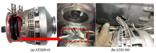
Figure 1.
Non-containment accident of the air turbine starter.
Therefore, many researchers have conducted a series of studies on the containment of high-energy rotors. By analyzing the sealing process, Hagg [11] proposed that the process of disk debris impacting the containment ring can be divided into two processes. In stage 1, the main objects to be considered are the loss of kinetic energy in the system and the dissipation of energy in plastic compression and shear strain. In stage 2, energy dissipation in plastic tensile strain is mainly considered. Giard [12] et al. proposed an empirical formula based on the maximum potential energy method to evaluate the thickness of the containment ring according to the kinetic energy of disk fragments. In addition, explicit finite element dynamics numerical simulation technology for impact problems is also widely used in structural containment problems. Li Juanjuan et al. [13] and Xuan Haijun et al. [14] conducted numerical simulation and experimental research on disk/casing containment and discussed the mechanism of casing containment and influencing factors of the containment process. Bai Conger et al. [15] explored the influence of groove depth on the U-type containment ring, and the results showed that groove depth not only affects axial containment capacity but also affects energy transfer between debris and the containment ring. Eric et al. [16] proposed a simulation method using ANSYS/LS-DYNA that could provide a more accurate prediction of container failure limits for a wider range of disk and container geometries. Liu et al. [17], through numerical simulation of high-energy rotor containment, analyzed that after the collision between disk fragments and containment, the impact zone and edge materials were respectively subjected to compression and shear. If no local perforation failure occurs, fragment escape is determined by the tensile strain energy of the impact zone and the extension zone of the shell material. He et al. [18] conducted a numerical study on the impact process of the fan blade/casing of an aero engine and evaluated the influence of stress initialization on the simulation. Liu et al. [19] studied an aircraft cooling turbine compressor disc seal for aircraft environmental control systems. By combining the experimental results with the numerical results, the process of disk fracture into three pieces and containment is studied.
Figure 2 shows the schematic diagram of the containment ring structure of the air turbine starter. The containment ring structure of the starter turbine disk usually has a U-type section. The rotor debris should be blocked by a containment ring both in the radial and axial directions. At present, the traditional design empirical formula is usually used to evaluate the thickness of the containment ring. However, the containment ring structure is composed of several parameters, such as thickness, groove depth, groove width, and groove height, so the traditional empirical formula is not enough to calculate and evaluate all the parameters of the containment ring. The simulation analysis method can consider the influence of structural parameters on the containment capacity, but the current research mainly focuses on containment evaluation and lacks consideration of structural parameters. Therefore, the traditional method cannot fully consider the influence of structural parameters on the containment capacity, which is not conducive to the optimal design of the containment structure of the air turbine starter.
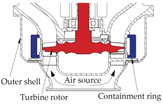
Figure 2.
U-type containment ring of the air turbine starter.
In this paper, the traditional design method is used to estimate the thickness of the containment ring, and the preliminary simulation analysis verifies its containment. On the basis of the preliminary design of the containment ring structure, the optimization design method is used to carry out parametric modeling of the containment ring structure, and the numerical simulation optimization is carried out to obtain the best design results. The corresponding test verification scheme was further developed to carry out the test study. The influence of structural parameters on the containment was analyzed based on numerical simulation and test verification results. In this paper, a multi-parameter optimization design method for a containment ring is formed by adopting the optimal Latin hypercube design, numerical simulation, response surface modeling, and a genetic algorithm. The methods of this study can be used to optimize the design of the containment ring of in-service or new air turbine starters, which has good engineering application value.
2. Preliminary Design
2.1. Traditional Design Method
Traditional containment design methods usually adopt the most representative maximum potential energy method, which is an analytical calculation method based on an empirical formula [12]. An initial structure can be estimated simply by using the maximum potential energy method. For reference to the starting turbine of the commonly used regional aircraft engine, the structure and shape of the wheel are shown in Figure 3. The material is TC11, the outer diameter of the blade tip ΦD0 = 157 mm, the thickness of the rim t1 = 20 mm, the working speed is 70,000 r/min, and the maximum speed that can be reached in free operation is 90,000 r/min. The physical information of the simulated turbine disk is shown in Table 1. The U-type section containment ring structure is shown in Figure 3. The structural parameters of the U-type section include thickness t, groove depth d, groove width w, and groove height h. These parameters are important to determine the containment of the containment ring structure because these four parameters determine the effective volume of the containment ring.
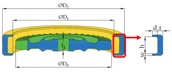
Figure 3.
U-type section parameters of the containment ring.

Table 1.
Physical information of the simulated turbine disk.
The thickness of the containment ring was estimated according to the formula of the potential energy method, which was summarized as follows [12]:
where η is the containment coefficient, σ0.2 is the yield ultimate strength, σb is the tensile ultimate strength, δ is the elongation, V is the effective volume of the containment ring, J is the rotational inertia of the turbine disk, w0 is the angular velocity of the turbine disk, Ek is the kinetic energy of the turbine disk, and Ep is the potential energy of the effective volume of the containment ring. When the containment coefficients η > 1, η = 1, and η < 1, they correspond to containment, critical containment, and non-containment states, respectively. In order to satisfy that the effective volume potential energy of the containment ring is not less than the kinetic energy of the turbine disk, η = 1 is set here. The thickness t = 10.6 mm was calculated according to the volume V of the containment ring. According to turbine disc diameter parameters, the tip clearance is retained by 1.5 mm, the inner diameter of the containment ring is finally obtained by ΦD1 = 160 mm, and the outer diameter ΦD2 = 196.2 mm. By referring to the structural parameters of the starter containment ring in active service, the groove depth of the containment ring (d = 7.5 mm, w = 3 mm, and h = 28 mm) was preliminarily set.
2.2. Containment Simulation Analysis
Considering the paper mainly studies the containment characteristics of the containment ring, it is necessary to ensure that the rupture energy of the simulated disk is consistent with that of the real disk, while the aerodynamic performance of the turbine disk can be ignored. In addition, the simulated straight blade is used to replace the complex curved blade. Not only the effect of the blade in the impact process can be considered, but also the test cost can be reduced and the simulation efficiency can be improved. The GH625 material has good ultimate strength and elongation, which can effectively improve the energy absorption effect of the containment ring during debris impact. Therefore, GH625 material is usually used as a typical material for the containment ring of the air turbine starter. The material of the turbine disk is TC11. The hexahedral mesh has obvious advantages over the tetrahedral mesh in terms of calculation accuracy, deformation characteristics, the number of meshes divided, and the degree of anti-distortion. Considering the containment ring as the main analysis object in the simulation process, a hexahedral mesh with high mesh quality was adopted, and at least 10 layers of mesh were arranged in the direction of the containment ring thickness. The finite element mesh model is shown in Figure 4. The number of units divided by tetrahedral mesh in the turbine disk is 270,000, and the number of units divided by 8-node hexahedral mesh in the containment ring is 220,000. The upper and lower parts of the containment ring were set as free boundary conditions. The rotation speed load of 90,000 r/min was applied to three disk fragments. The calculation time was 3 ms, and the calculated steps were 100.
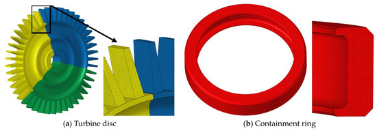
Figure 4.
FEM model.
LS-DYNA was used for numerical simulation of turbine disc containment, and the Johnson-Cook constitutive equation [20] was introduced, which could better simulate the hardening, strain rate, and temperature softening effects of materials. Its constitutive equation is:
where σe is von Mises equivalent stress. is the equivalent plastic strain. is the dimensionless equivalent plastic strain rate. ε* = ε*/ε0, is the reference strain rate. ε* is the current strain rate. T* is a dimensionless temperature. A, B, n, C, and m are material constants. A is the yield stress. B and n are strain-hardening effects. C is the strain rate constant, and m is the temperature constant. The Johnson-Cook cumulative damage criterion based on continuous damage mechanics was adopted for material failure [21], and the damage parameter D was defined as:
where failure strain is defined as:
where σ* = P/σeff = −Rσ is the mean value of principal stress under hydrostatic pressure, σeff is Von-Mises equivalent stress, Rσ is stress triaxial degree, and D1~D5 is the failure constant. The material and failure model parameter values are listed in Table 2.
Table 2.
J-C model material parameters [22].
Figure 5 shows the numerical simulation results of disk containment, and the equivalent stress distribution diagram of the turbine disk and containment ring is given. Figure 6 shows the change in kinetic energy and internal energy of turbine disk fragments and the containment ring with time during impact. It can be seen that 0.09 ms turbine disk fragments began to contact the inner wall of the containment ring after 1/3 of the disk disc burst, and the kinetic energy of 0.48 ms turbine disk fragments was almost completely absorbed by the containment ring, leaving the impact mark of turbine disk fragments on the inner wall of the containment ring, but the containment ring was not broken, and no fragments flew out axially, resulting in successful containment. It can be seen from the simulation results that after being impacted by three fragments, the containment ring is relatively circular but not fully transformed into a triangle; the outer diameter deformation of the containment ring is 13.7%. The thickness of the containment ring is 10.6 mm, which has a containment margin that is too large, which is very detrimental to the weight reduction of the containment ring structure. Therefore, parameters of the containment ring structure can be optimized to reduce the mass on the premise of satisfying the containment effect, thus improving the starter’s performance.
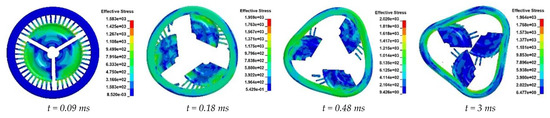
Figure 5.
Numerical simulation results of the initial containment ring (units: MPa).
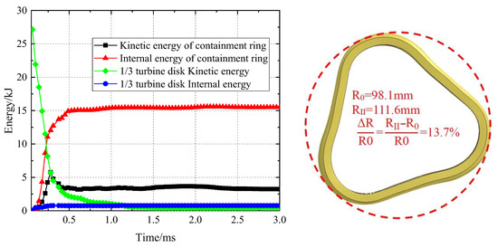
Figure 6.
Energy changes during the impact.
3. Optimal Design Method
3.1. Multi-Parameter Optimization Process
The multi-parameter optimization process platform, as shown in Figure 7, was established to optimize multiple parameters of the containment ring section simultaneously. Firstly, the design variables and their value range that need to be optimized are defined, and parametric modeling is carried out. The U-type section structure of the containment ring has multiple parameters, and the simulation calculation of transient impact dynamics takes a long time. If the combination of each parameter in the constrained space is optimized after the simulation calculation results, the time cost is very high. Therefore, approximate models can be used to replace complex dynamic simulation calculations, greatly reducing the time consumption in the optimization process [23,24]. Through the DOE experimental design method, a certain number of sample points within the range of variables are generated, automatic simulation of sample points is realized based on the optimization platform, simulation results are extracted as the sample base to construct the approximate model, an optimization algorithm is adopted for global optimization, the optimized design parameters are obtained for finite element simulation, and the simulation results are compared with the predicted results of the approximate model. If the error is within the allowed range, the optimization will end; otherwise, this group of samples will be put into the sample library, and the approximate model will be rebuilt and optimized until the end.
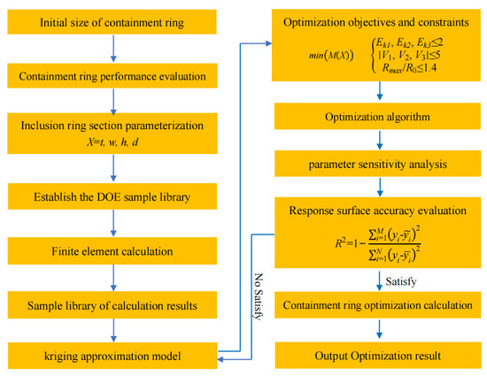
Figure 7.
Multi-parameter optimization containment ring design process.
3.2. Mathematical Model of the Optimization Problem
The minimum mass M of the U-type containment ring is selected as the optimization objective. Meanwhile, the U-type containment ring with mass M should meet the containment requirements after the turbine disk of a certain type of air turbine starter is broken into three equal parts at free running speed. The four parameters t, h, d, and w are selected as optimization variables, as shown in Figure 3. As described in the literature [12], the kinetic energy absorbed by deformation of the containment ring during disk fragment impact is about 0.975 of the total energy, so the thresholds of residual kinetic energy and axial velocity are selected as 2 kJ and 5 m/s, respectively. Since the containment ring will be stretched during impact, a clearance should be set to allow the containment ring to deform and prevent interference with the surrounding structure. Here, the clearance diameter around the ring where the deformation is allowed is 140% of the original outer diameter of the containment ring [17]. Therefore, the maximum outer diameter of the limiting containment ring after deformation is less than or equal to 140% of the original outer diameter.
According to the numerical simulation results of the initial containment ring, the parameter range of different structures in DOE sample generation is listed in Table 3. The lower limit of the thickness of the containment ring is reduced by 1/3 relative to the initial value, and the upper and lower limits of the groove depth are increased and decreased by 1/3 relative to the initial value. The upper and lower limits of groove edge width increase and decrease by 1/2 relative to the initial values, respectively. The distance of the groove height is not less than 20 mm, the maximum thickness of the turbine disc, and not more than 1.5 times the maximum thickness of the turbine disc. Hence, the optimization problem can be described by Equation (5).
where Ek1, Ek2, and Ek3 respectively represent the remaining kinetic energy of the debris after the turbine disks tricyclic rupture and impact on the containment ring. v1, v2, and v3 represent the axial velocities of the three fragments, respectively. R0 is the original outside diameter of the containment ring, and Rmax is the diameter of the outer tangential circle after the containment ring is changed into a triangle by debris impact.
Table 3.
Range of structural parameters.
3.3. Building an Optimization Platform
In order to realize the automatic optimization process of structural parameters, three-dimensional model generation, finite element mesh division, boundary conditions, control information setting, and result solving are realized automatically by combining batch processing commands. The automatic design flow of the sample library is shown in Figure 8.
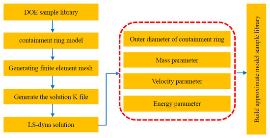
Figure 8.
Process of sample library automatic generation.
The Kriging approximate model is a model based on structural analysis and variogram theory to perform unbiased optimal estimation of regionalized variables in a limited region and can be used to solve problems with a high degree of nonlinearity to obtain an ideal fitting effect [25,26]. This method is suitable for the case of small sample point disturbances, and the calculation speed of this algorithm is faster than other methods. Compared with other approximate models, such as nonlinear regression, neural networks, and sparse grids, they are used on fewer occasions and correspond to the corresponding sample point generation methods. Since the data points in the DOE sample library need to be calculated by finite element and evaluated by error, the results of the sample library have high accuracy; that is, compared with the fitting method, the interpolation method is better, so this paper adopts the Kriging method to generate response surfaces. The Kriging model can be expressed as:
where f(x) represents the objective function. y(x) is the function that we solved, which represents the entire model of our sample space. z(x) represents the local deviation of the overall model, and its covariance form is as follows:
where R represents the correlation matrix and R(xi,xj) represents the correlation function between any two sample points xi and xj. The most Gaussian correlation function can be used to express the correlation between sample points.
where nv represents the number of variables. and represent the KTH element of sample points xi and xj, and θk represents the unknown relevant parameters of the fitting model. After determining the correlation function, the relationship between the approximate response of f(x) and the observation point x is established as follows:
where . f, y, and rT(x) are all ns dimensional column vectors. f is the target response value of each design point. y is the unit column vector. rT(x) is the correlation between x and sample points, which can be expressed as rT(x) = [RT(x,x1), R(x,x2), …, R(x, xm)]T.
In the optimization platform design, the value range of optimization variables is first given, and a certain number of sample point libraries are generated using the optimized Latin square experiment method. The sample points are automatically modeled and simulated to obtain the deformation outside diameter, mass, velocity, and other information to form the sample result library. The mapping relationship between structural parameters and results is constructed by the Kriging approximation model. For the multi-parameter sample space, the multi-island genetic algorithm (MIGA) has obvious advantages [27]. This optimization algorithm can effectively improve the search efficiency of the traditional genetic algorithm, support distributed optimization better, and avoid the local optimal solution more effectively [28]. Therefore, the algorithm can support multi-parameter optimization better. The genetic algorithm is used to optimize the structural parameters according to the optimization objectives, and the optimized structural parameters are simulated and calculated, and the results predicted by the approximate model are compared. If the error is within the allowed range, the final optimization results will be obtained; otherwise, the set of data will be added to the sample database to continue to build a more accurate approximate model. The re-optimization continues until the error of the approximate model is within the allowable range.
3.4. Weight Analysis of Structural Parameters
Based on the initial containment ring, the influence of structural parameters on containment was analyzed using the optimal Latin Hypercube Experimental design method (DOE) and response surface modeling. The DOE method can make the value range of the sectional structural parameters of the containment ring have very good spatial filling and equilibrium, so that the influence of the interrelation between the structural parameters on the containment can be fully reflected and provide a sample basis for the response surface analysis. The response surface can well fit the complex response relationship between structural parameters and Ek and has good robustness.
According to the numerical simulation results of the initial containment ring, the parameter range of different structures in DOE sample generation is listed in Table 3. The lower limit of the thickness of the containment ring is reduced by 1/3 relative to the initial value, and the upper and lower limits of the groove depth are increased and decreased by 1/3 relative to the initial value. The upper and lower limits of groove edge width increase and decrease by 1/2 relative to the initial values, respectively. The distance of the groove height is not less than 20 mm, the maximum thickness of the turbine disc, and not more than 1.5 times the maximum thickness of the turbine disc.
The objective function f(x) in the Kriging model can be a first-order, second-order, third-order, or fourth-order polynomial. In order to obtain a more accurate model, the fourth-order polynomial function is used here, and the number of samples required to construct the model can be selected according to Equation (10) [29].
where Kmin is the minimum number of sample points and N is the number of input variables. When N = 4, the minimum number of samples is Kmin = 23. Here, the sample library is generated with the sample number K = 30, and numerical simulation is carried out. The sample library of results is shown in Table 4.
Table 4.
Sample library of numerical simulation results.
The response surface function is shown in Equation (11). Ek is the output variable f(x) as the result of the model, and the U-type ring structure parameter is the input variable xn of the model.
where β0, β1, …, β4N, and βij were the parameters to be estimated. After calculation, response surface model Equation (12) can be expressed as:
Because the response surface model has some errors, error analysis is needed to ensure the accuracy of the model. The fitting accuracy evaluation formula for the response surface model is as follows [30]:
where is the ith point’s approximate model prediction; yi is the verification value for the ith point. The larger the value of R2, the higher the degree of fit. When R2 ≥ 0.9, the model is successfully established. The fitting accuracy of the response surface model in this model is R2 = 0.92, so the response surface model is successfully built. Through calculation and analysis based on the response surface model, the influence weights of various structural parameters on the residual kinetic energy of debris and the volume of the containment ring are obtained. As shown in Figure 9, the containment ring thickness t is the biggest factor affecting the residual kinetic energy of debris, accounting for nearly 38% of the weight. The parameters d, w, and h decrease in sequence.
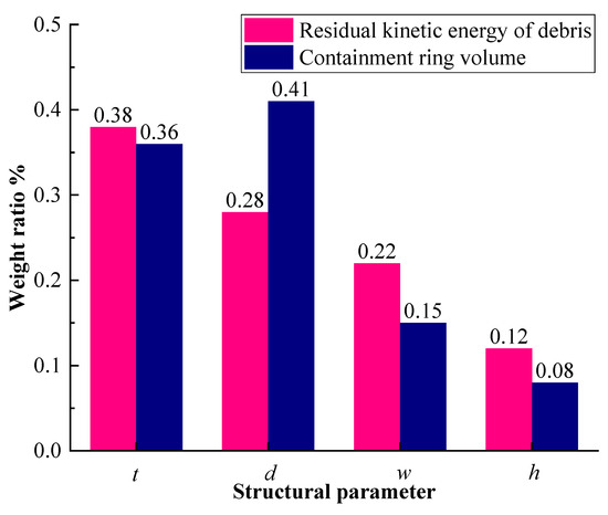
Figure 9.
Weight of the influence of structural parameters.
3.5. Optimization Results and Analysis
Considering the spatial location restrictions of other external components, the containment condition is set so that the containment ring will not be broken and the outer diameter deformation does not exceed 40% [12]. The iterative optimization process is shown in Figure 10. Parameters of containment ring thickness and groove depth converge after 130 iterations.
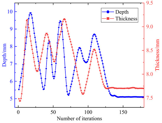
Figure 10.
Iterative optimization of thickness and groove depth.
The structure of the initial U-type containment ring was optimized, and the parameters before and after optimization are shown in Table 5. The weight of the optimized containment ring is 1421 g, and the weight reduction effect reaches 26.5%. All parameters of the optimized containment ring meet the constraint conditions.
Table 5.
Comparison before and after optimization.
In order to verify the containment capacity of the optimized containment ring and explore the influence of parameters, such as the thickness and groove depth of the containment ring on the containment capacity, containment rings with the four structural parameters shown in Table 6 were designed according to the above optimization results for simulation analysis. The calculated rotation speed was 90,000 r/min. The No. I containment ring was defined as the containment state by the simulation results. The containment rings No. I and No. II were selected for comparative analysis with different ring thicknesses, while the groove depth of the ring was the same. Containment rings No. II and No. III were selected for comparison. While the containment ring thickness was kept the same, the containment capability increased with the groove depth of the ring. Finally, the containment rings No. I and No. IV are selected to compare and analyze the influence of groove depth reduction to a certain extent on the containment when the thickness is the same.
Table 6.
Parameters after containment ring optimization.
Figure 11 is the result of a numerical simulation with optimized parameters. Containment ring No. I: t = 7.9 mm, d = 6.1 mm; the simulation result is containment. In the simulation results, when t = 0.09 ms, the turbine rotates into three equal parts and has an impact on the containment ring. Subsequently, the turbine disc blades rub against the inner wall of the containment ring, resulting in blade damage and spatter. The containment ring gradually becomes a triangle. Containment ring No. II: t = 7.6 mm, d = 6.1 mm. The simulation result is non-containment. When t = 0.09 ms, the turbine disc rotates in three equal parts and impacts the containment ring. When t = 0.09~0.48 ms, friction occurs between the turbine disc blades and the inner wall of the containment ring, and the blades are damaged. When t = 0.48 ms, the containment ring began to break. When t = 1.2 ms, the containment ring was evenly pulled into three sections. By comparing the simulation results of No. I and No. II containment rings, it can be seen that the containment capacity can be improved by increasing the thickness of the containment rings under the same groove depth.
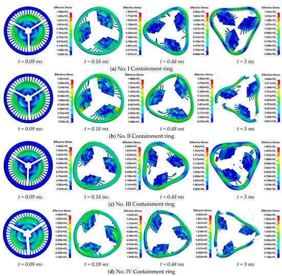
Figure 11.
Simulation process of the turbine disk impacting the containment ring.
No. III containment ring: t = 7.6 mm, d = 8.0 mm. The simulation result is the containment state. When t = 0.09 ms, the turbine disc rotates in three equal parts and impacts the containment ring. When t = 0.48 ms, the containment ring gradually becomes triangular, and the turbine disc rotates inside the ring all the time. No. IV containment ring: t = 7.9 mm, d = 5.5 mm: simulation results are non-containment. When t = 0.09 ms, the turbine disc rotates in three equal parts and impacts the containment ring. Afterwards, friction occurs between the turbine disc blades and the inner wall of the containment ring. When t = 0.48 ms, the containment ring began to break. When t = 1.2 ms, the containment ring was evenly pulled into three sections.
Through the simulation analysis of No. I, II, III, and IV containment rings, it can be seen that the containment capacity of containment rings can be improved by increasing the groove depth size under the condition of the same thickness of containment rings. However, it is worth noting that when the depth of the containment ring groove is reduced to a certain extent (d = 5.5 mm), simply increasing the thickness of the containment ring cannot improve the containment capacity of the ring. Therefore, the influence of the groove depth parameter on the containment capacity of the containment ring is second only to that of the thickness parameter, which is consistent with the weight analysis results of the structural parameters of the containment ring. The trajectory of the disk fragment may change along the axial direction during the impact with the containment ring. Therefore, improving the groove depth parameter of the containment ring can effectively limit the axial motion trajectory of disk fragments, thus improving the protective capacity of the ring.
Figure 12 shows various energy variation processes in the turbine disc and containment ring. As shown in Figure 12a, during the impact of the No. I containment ring, the energy changes rapidly within t = 0~0.48 ms. After t = 0.48 ms, the energy of each component basically no longer changes, and the impact process is over. In numerical simulation, the kinetic energy of 1/3 turbine disk before and after impact is Ea = 27.2 kJ and Ek = 1.24 kJ, respectively, and the kinetic energy decreases by 95.4%. Internal energy Ec = 23.7 kJ of containment ring; compared with the containment ring before optimization, Ec increased by 8.4 kJ. Obviously, because the optimized containment ring is more fully deformed and absorbs more energy, the kinetic energy of the containment ring is significantly increased. From Figure 12b, it can be seen that during the impact of the No. II containment ring, the energy changes rapidly within t = 0~0.48 ms. After t = 0.56 ms, the energy of each component basically no longer changes, and the impact process is over. In numerical simulation, the kinetic energy of 1/3 turbine disk before and after impact is Ec = 27.2 kJ and Ek = 0.51 kJ, and the kinetic energy decreases by 98.12%.

Figure 12.
Energy change and deformation in the containment process.
By comparing the kinetic energy and internal energy of the containment ring during the impact, it is obvious that the containment ring absorbed most of the kinetic energy, and the internal energy increased significantly while the kinetic energy of the containment ring also increased to a certain extent. This indicates that the optimized containment ring can absorb the energy of disk fragments more effectively on the premise of providing effective containment, which is very favorable for the weight reduction design of the containment ring structure [31].
4. Test Verification
In order to verify the containment capacity of the optimized containment ring and to study the influence of thickness and groove depth on the containment capacity, the containment rings No. I, II, III, and IV were tested on the high-speed rotating test equipment. The overall structure and test system of the containment test are shown in Figure 13a. The disk is connected to the driven shaft of the test bench. The containment ring is the most important protective part after the turbine disc of the turbine starter is broken, so the influence of other parts is ignored in the test verification. Considering the containment ring of the air turbine starter is in a nearly free boundary condition state in actual work, the containment ring in the test is also set in a free boundary condition state by only using glue to fix it. The installation form of the containment ring refers to SAE Aerospae-ARP-85F [32], and the installation of test parts is shown in Figure 13b. The turbine disc rupture mode was controlled to have three equal parts by pre-cutting grooves. In this case, the translational kinetic energy generated by the turbine disc fragments is the maximum, and the damage to the containment ring is the maximum.
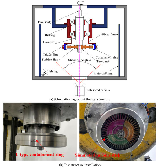
Figure 13.
Schematic diagram of the test structure.
The test measurement and control system includes three parts: a trigger signal system, a rotation speed measurement and control system, and a high-speed camera system. Before the test, the trigger wire was wrapped around the inner wall of the containment ring. When the disk is broken in tripartite division, the wound trigger wire inside the containment ring will be cut off by impact, and a trigger signal is formed. Moreover, the speed control system is triggered to cause the test bench to slow down and stop in time. At the same time, a high-speed camera mounted at the bottom of the test stand is triggered to film the containment impact process.
The turbine disc rupture speed was 90,000 r/min. The damage process of No. I, II, III, and IV containment rings was captured by high-speed photography. As shown in Figure 14a,c, at t = 0.1 ms, the disc began to break, and then the disc fragments began to hit the containment ring. When t = 0.48 ms, the containment ring morphed into a triangle, and the deformation of the containment ring remained basically unchanged in the subsequent time, which was consistent with the simulation impact process. In the process of impact, the motion path of the disc fragments changed to some extent. As shown in Figure 14b,d, the results of containment rings No. II and No. IV were in a non-containment state. When t = 0.1 ms, the disk began to break and then hit the containment ring; when t = 0.48 ms, the containment ring was completely broken and separated, showing a non-containment state.
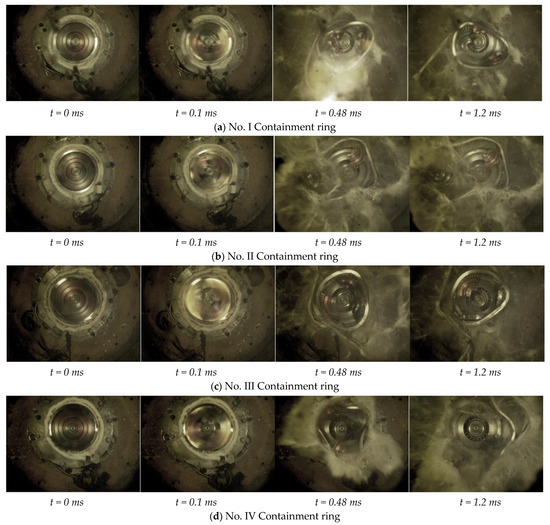
Figure 14.
High-speed photography of the turbine disk impacting the containment ring.
The test disk and containment ring debris are shown in Figure 15. In No. I and No. II tests, the groove depths of rings were the same; the No. I ring was in the containment state as the t = 7.9 mm, and the No. II ring was in the non-containment state as the t = 7.6 mm. The results show that the containment capacity can be improved by increasing the thickness of the containment ring when the groove depth parameter is the same, which is consistent with the simulation analysis results. By comparing the results of No. II and No. III containment rings, it can be seen that the containment capacity of containment rings can be improved by increasing the groove depth of containment rings when the thickness is the same.
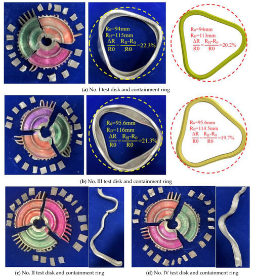
Figure 15.
Results of debris and radial deformation of test pieces.
However, by comparing the results of containment rings No. I and No. IV, it can be seen that the containment capacity of containment rings with the same thickness will be reduced when the groove depth parameter decreases to a certain extent. According to the measurement results of radial deformation of the containment ring in Figure 15a,b, Compared with the initial containment ring structure, the radial deformation of the optimized I and III containment rings is 22.3% and 21.3%, respectively, which is significantly higher than the initial containment ring’s 13.7%. On the premise of ensuring the performance of the containment ring, the optimized containment ring has fuller deformation and a better energy absorption effect. According to the comparison of experimental and simulation results in Table 7, the deformation of No. I and No. III containment rings is consistent with the numerical simulation results, and the radial variable errors are 2.1% and 1.6%, respectively, indicating that the containment ring optimization method proposed in this paper is reasonable and feasible.
Table 7.
Comparison of test and simulation results.
5. Conclusions
In this paper, parametric modeling, containment numerical simulation, DOE sample library construction, parameter weight analysis, and genetic algorithm optimization are used to develop a U-type cross-section containment ring structure optimization design method. The multi-parameter optimization design of the U-type containment ring structure was carried out according to the thickness t, width w, depth d, and height h of the U-type containment ring section. This method can avoid the over- and under-optimization problems caused by the mechanical optimization of a single parameter. The experimental and simulation deviations of the optimized containment ring deformation are less than 5%. The results show that the optimization method is reasonable and feasible and can provide a certain reference for the optimal design of the starter containment structure.
Based on the response surface model, the influence weights of different section parameters of the containment ring on the residual kinetic energy and the volume of the containment ring are analyzed. It is found that the thickness of the containment ring and the depth of the groove have the greatest influence on the residual kinetic energy and volume of the debris. In particular, the thickness parameter is the biggest factor affecting the residual kinetic energy of debris, accounting for nearly 38% of the weight, and the descending sequence is groove depth d, groove width w, and groove height h. This indicates that the parameters of containment ring thickness and groove depth should be the most considered in the optimization of containment ring structure parameters. Increasing the thickness and groove depth of the containment ring is conducive to improving the containment effect.
According to the containment ring optimization design method proposed in this paper, four containment rings with different section parameters were designed based on the containment ring optimization results to carry out experimental verification of the containment capacity. The results show that the containment state of the containment ring can be accurately obtained by using the numerical simulation optimization method provided in this paper, and the maximum radial deformation of the optimized containment ring can reach 22.3%, which indicates that the optimized containment ring can absorb the energy of disk fragments more effectively under the premise of providing effective containment capability. In addition, with the same containment capability, the weight reduction effect of an optimized containment ring can reach 26.5%, which is a great improvement over the redundant design of the containment ring structure. The weight of the containment ring can be used as a reference for the optimization results. However, there is a limit to the weight optimization result of the containment ring, and when the weight of the containment ring is reduced to a certain extent, it will lead to non-containment.
Author Contributions
Data curation, Y.Z. and Z.H.; formal analysis, Z.H.; funding acquisition, J.L. and D.M.; methodology, Z.H.; project administration, H.X. and X.G.; resources, Z.F.; software, Y.Z.; supervision, H.X.; writing—original draft, Y.Z.; writing—review and editing, Y.Z. All authors have read and agreed to the published version of the manuscript.
Funding
The project was supported by the National Science and Technology Major Projects of China (2017-IV-0006-0043) and the research fund of the AECC Hunan Aviation Powerplant Research Institute.
Informed Consent Statement
Not applicable.
Data Availability Statement
The data underlying the results presented in this paper are not publicly available at this time.
Conflicts of Interest
The authors declare no conflict of interest.
Nomenclature
| t | thickness of the containment ring |
| d | Groove depth of the containment ring |
| w | groove width of the containment ring |
| h | groove height of the containment ring |
| η | containment coefficient |
| σ0.2 | yield ultimate strength |
| σb | tensile ultimate strength |
| δ | elongation |
| V | effective volume of the containment ring |
| J | rotational inertia of the turbine disk |
| w0 | angular velocity of the turbine disk |
| Ek | kinetic energy of the turbine disk |
| Ep | potential energy of the effective volume of |
| σe | von Mises equivalent stress |
| plastic strain rate | |
| equivalent plastic strain rate | |
| reference strain rate | |
| ε* | current strain rate. |
| T*m | dimensionless temperature |
| A | yield stress |
| B and n | strain-hardening effects |
| C | strain rate constant |
| m | temperature constant |
| D | damage parameter |
| σ* | mean value of the principal stress under hydrostatic pressure |
| σeff | von Mises equivalent stress |
| Rσ | stress triaxial degree |
| D1~D5 | failure constant |
| Ek1, Ek2, and Ek3 | remaining kinetic energies of the turbin |
| v1, v2, and v3 | axial velocities of the three fragments |
| R0 | original outside diameter of the containment |
| Rmax | diameter of the outer tangential circle |
| f(x) | objective function. |
| y(x) | solved function |
| z(x) | local deviation of the overall model |
| R | correlation matrix |
| nv | number of variables |
References
- Hao, W.; Henghui, Y.; Yufang, L. Over view of aircraft second power system technology. China J. Inf. Syst. 2014, 4, 8–39. [Google Scholar]
- Yongqiu, B.; Duo, J.; Yonghua, Y.; Dongwu, G.; Bingjie, Z.; Bin, H. Development status and trend research of starter for aero engine. In Proceedings of the 4th China Aviation Science and Technology Conference; Chinese Society of Aeronautics and Astronautics: Shenyang, China, 2019; pp. 659–665. [Google Scholar]
- Liu, W.; Tian, H.; Chen, Y.; Pan, S.; Huang, X. Matching performance calculation method for aeroengine air starting systems. J. Propuls. Technol. 2020, 41, 277–284. [Google Scholar]
- Moussa, N.A.; Whale, M.D.; Grozmann, D.E.; Zhang, X.J. The Potential for Fuel Tank Fire and Hydrodynamic Ram from Uncontained Aircraft Engine Debris; US Department of Transportation, Federal Aviation Administration: Washington, DC, USA, 1997; 20591DOT/FAA/AR-96/95.
- Xuan, H.; Lu, X.; Hong, W.; Liao, L.-F. Review of aero-engine case containment research. J. Aerosp. Power 2010, 25, 1860–1870. [Google Scholar]
- Xuan, H.J.; Wu, R.R. Aero-engine turbine blade containment tests using high-speed rotor spin testing facility. Aerosp. Sci. Technol. 2006, 10, 501–508. [Google Scholar] [CrossRef]
- FAA Federal Aviation Regulations. Airworthiness Standards: Aircraft Engines; Federal Aviation Administration: Washington, DC, USA, 1984.
- CARR-25-R4; Airworthiness Standards for Transport Aircraft. Civil Aviation Administration of China: Beijing, China, 1985.
- In-Flight Engine Shut down Involving Airbus A330-302 B-18358; ATSB Transport Safety Report; Australian Transport Safety Bureau: Darwin, Australia, 2013.
- Uncontained Engine Starter Failure—General Electric CF6-80E1-A3—Darwin Aerodrome; Report No: AO-2007-052; Australian Transport Safety Bureau: Darwin, Australia, 2008. Available online: https://hdl.handle.net/10070/671105 (accessed on 29 May 2023).
- Hagg, A.C.; Sankey, G.O. The containment of disk burst fragments by cylindrical shells. J. Eng. Power Trans. ASME 1974, 96, 114–123. [Google Scholar] [CrossRef]
- Giard, J.R. Air Turbine Starter Turbine Wheel Containment. SAE Trans. 1984, 93, 459–463. [Google Scholar]
- Li, J.-J.; Xuan, H.-J.; Liao, L.-F.; Hong, W.-R.; Wu, R.-R. Penetration of disk fragments following impact on thin plate. J. Zhejiang Univ. A 2009, 10, 677–684. [Google Scholar] [CrossRef]
- Xuan, H.-J.; Liu, L.-L.; Feng, Y.-M.; He, Q.; Li, J.-J. Containment of high-speed rotating disk fragments. J. Zhejiang Univ. A 2012, 13, 665–673. [Google Scholar] [CrossRef]
- Bai, C.; Xuan, H.; Huang, X.; He, Z.; Hong, W. Containment ability and groove depth design of U type protection ring. Chin. J. Aeronaut. 2016, 29, 395–402. [Google Scholar] [CrossRef]
- Stamper, E.; Hale, S. The use of LS-DYNA models to predict containment of disk burst fragments. In Proceedings of the 10th International LS-DYNA User Conference, Dearborn, MI, USA, 8–10 June 2008; pp. 1-1–1-9. [Google Scholar]
- Liu, Z.; Ju, X.; Xuan, H.; Chen, L.; He, Z. Containment Mechanism and Structural Optimization Research for Disk Containment of High Energy Rotor. Chin. J. High Press. Phys. 2022, 36, 1–7. [Google Scholar]
- He, Q.; Xuan, H.; Liu, L.; Hong, W.; Wu, R. Perforation of aero-engine fan casing by a single rotating blade. Aerosp. Sci. Technol. 2013, 25, 234–241. [Google Scholar] [CrossRef]
- Liu, L.L.; Xuan, H.J.; Zhang, N.; Hong, W.R. Research on compressor disc containment of a cooling turbine. In Proceedings of the 22nd Proceedings of the Conference on Structural Engineering, Urumqi, China, 9–11 August 2013; Engineering Mechanics Press: Beijing, China, 2013; Volume III, pp. 190–195. [Google Scholar]
- Johnson, G.R.; Cook, W.H. A constitutive model and data for metals subjected to large strains, high rates and high temperatures. In Proceeding of the Seventh International Symposium on Ballistics, The Hague, The Netherlands, 19–21 April 1983; pp. 541–547. [Google Scholar]
- Johnson, G.R.; Cook, W.H. Fracture characteristics of three metals subjected to various strains, strain rates, temperatures and pressures. Eng. Fract. Mech. 1985, 21, 31–48. [Google Scholar] [CrossRef]
- Fan, X. Numerical Simulation and Structural Optimization of U-Section Containment Rings. Ph.D. Thesis, Zhejiang University, Hangzhou, China, 2021. [Google Scholar]
- Tong, S.; He, S.; Tong, Z.; Fan, H.; Li, Y.; Li, M.; Tan, D.; Zhong, Y. Lightweight Design Method Based on Combined Approximate. Model. China Mech. 2020, 31, 1337–1343. [Google Scholar]
- Chen, L.; Zang, W. Multi Objective Optimization Design of Engine Hood Based on Kriging Model. China Mech. Eng. 2013, 24, 3014–3018. [Google Scholar]
- Shi, Y.; Lu, Z.; He, R.; Zhou, Y.; Chen, S. A novel learning function based on Kriging for reliability analysis. Reliab. Eng. Syst. Saf. 2020, 198, 106857. [Google Scholar] [CrossRef]
- Simpson, T.W.; Mauery, T.M.; Korte, J.J.; Mistree, F. Kriging Models for Global Approximation in Simulation-based Multidisciplinary Design Optimization. AIAA J. 2001, 39, 2233–2241. [Google Scholar] [CrossRef]
- Holland, J.H. Adaptation in Natural and Artificial Systems, 1st ed.; University of Michigan Press: Ann Arbor, MI, USA, 1975. [Google Scholar]
- Zhao, D.; Wang, Y.; Cao, W.; Zhou, P. Optimization of Suction Control on an Airfoil Using Multi-island Genetic Algorithm. Procedia Eng. 2015, 99, 696–702. [Google Scholar] [CrossRef]
- Haftka, R.T.; Villanueva, D.; Chaudhuri, A. Parallel surrogate-assisted global optimization with expensive functions—A survey. Struct. Multidiscip. Optim. 2016, 54, 3–13. [Google Scholar] [CrossRef]
- Tian, Y.; Zhang, Y. Study on finite Element model updating of existing bridge based on response surface method. J. Wuhan Univ. Technol. 2020, 42, 19–25. [Google Scholar]
- He, Z.; Xuan, H.; Bai, C.; Hu, Y.; Cong, P.; Bai, H.; Miao, Y.; Hong, W. Containment tests and analysis of soft wall casing fabricated by wrapping Kevlar fabric around thin metal ring. Aerosp. Sci. Technol. 2017, 61, 35–44. [Google Scholar] [CrossRef]
- SAE Aerospace. SAE Aerospace-ARP-85F. Air Conditioning Systems for Subsonic Airplanes; Society of Automotive Engineers (SAE) Aerospace: Warrendale, PA, USA, 2012; p. 27. [Google Scholar]
Disclaimer/Publisher’s Note: The statements, opinions and data contained in all publications are solely those of the individual author(s) and contributor(s) and not of MDPI and/or the editor(s). MDPI and/or the editor(s) disclaim responsibility for any injury to people or property resulting from any ideas, methods, instructions or products referred to in the content. |
© 2023 by the authors. Licensee MDPI, Basel, Switzerland. This article is an open access article distributed under the terms and conditions of the Creative Commons Attribution (CC BY) license (https://creativecommons.org/licenses/by/4.0/).