Abstract
Fiber-optic gyroscopes (FOGs) have become one of the most important elements of modern inertial navigation systems due to their high accuracy, reliability, and independence from external signals such as satellite navigation. This review analyzes and discusses the key FOG architectures: interferometric (IFOG), resonant (RFOG), digital (DFOG), and hybrid (HFOG). The concepts of their functioning, structural features, and the main advantages and limitations of each architecture are examined. Particular focus is placed on advanced signal-processing and error-compensation algorithms, including filtering techniques, noise suppression, mitigation of thermal and mechanical drifts, and emerging machine learning (ML) based approaches. The analysis of these architectures is carried out in terms of major parameters that determine accuracy, robustness, and miniaturization potential. Various applications of FOGs in space systems, ground platforms, marine and underwater navigation, aviation, and scientific research are also being considered. Finally, the latest development trends are summarized, with a particular focus on miniaturization, integration with additional sensors, and the introduction of digital and AI-driven solutions, aimed at achieving higher accuracy, long-term stability, and resilience to real-world disturbances.
1. Introduction
Fiber-optic gyroscopes (FOGs) have been developed over many decades, from laboratory experiments to their present status as a key element of high-performance navigation systems. They offer autonomy, stability, and longevity in areas where satellite-based navigation is non-existent or unreliable [1,2].
FOGs have multi-purpose applications in a wide range of domains (aviation, marine and underwater, space systems, ground vehicles, and scientific research) as an important tool for orientation and navigation in highly dynamic operational environments [3].
The principles of FOGs technology were established in 1976, when Vali and Shorthill first demonstrated the operation of a fiber-optic interferometer based on the Sagnac effect [4]. In the following decades, laboratory experiments quickly became practical and commercial. The transition to mass production was carried out by several industrial companies, including KVH Industries and Honeywell, which made a significant contribution to the introduction of FOGs into aviation, marine, and navigation systems [5]. Modern FOGs are characterized by high accuracy, vibration resistance, and a lack of moving parts, which makes them a serious alternative to laser gyroscopes.
The basic configuration of an IFOG, which operates based on the Sagnac effect, is illustrated in Figure 1.
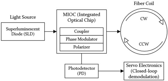
Figure 1.
Schematic configuration of an IFOG illustrating a typical system-level architecture, including the light source, multifunction integrated optical chip (MIOC) with an integrated coupler, phase modulator, and polarizer, the fiber coil, photodetector, and closed-loop signal-processing electronics.
Despite such success, several challenges remain. FOGs are still susceptible to changes in temperature and mechanical loads, and their properties are adversely affected by noise and bias drift, particularly in miniaturization. These problems are especially relevant due to the growing need for small, energy-efficient, and robust inertial systems. The most recent trends address these issues by integrating MEMS sensors, sophisticated digital signal-processing approaches, machine-learning algorithms, and real-time error-compensation solutions [6].
The importance of FOGs is further highlighted by the vulnerabilities of global navigation satellite systems (GNSS). GPS and other constellations can be jammed and spoofed, particularly in conflict areas, high latitudes, and underwater regions [7,8,9]. For example, in [10], GPS interference was reported over 46,000 times in the Baltic in 2023–2024, affecting commercial airlines including Ryanair, Wizz Air, British Airways, and Finnair. Similar disturbances were reported in the Middle East and the South China Sea [11]. Such cases underline the urgent need for robust autonomous navigation systems in UAVs, underwater robots, ground robots, and transport systems, where FOGs play a central role [12].
The main research question of the current review is to understand how modern FOG architectures, such as interferometric (IFOG), resonant (RFOG), digital (DFOG), and hybrid (HFOG), together with advanced signal-processing methods, help address the main limitations of such systems: bias drift, temperature and mechanical effects, miniaturization, and power consumption.
The main types of FOGs and the distinctive principles of their design are described below:
- Interferometric FOGs (IFOGs) are a classical scheme based on the direct measurement of the phase shift of oncoming optical beams.
- Resonator FOGs (RFOGs) use high-quotient fiber resonators to enhance the Sagnac phase shift and achieve high sensitivity with smaller coil sizes.
- Digital FOGs (DFOGs) use digital modulation and demodulation techniques to enhance noise reduction and resistance to temperature changes.
- Hybrid FOGs (HFOGs) combine the principles of interferometric, resonator, and digital circuits, providing an optimal balance of sensitivity, compactness, and energy efficiency, paving the way for next-generation integrated optical solutions.
A comparison of these architectures is summarized in Table 1.

Table 1.
Comparison of main FOG architectures.
As shown in Table 1, IFOG and RFOG architectures represent mature technologies. IFOGs provide a balanced trade-off between accuracy, robustness, and system maturity, while RFOGs offer improved compactness and sensitivity at the cost of increased optical complexity.
In contrast, digital and HFOG architectures represent emerging system-level approaches, whose performance strongly depends on specific implementation details, signal-processing strategies, and integration level. This comparison highlights both the current state of mature FOG technologies and the future potential of DFOG and HFOG architectures for compact and intelligent inertial navigation systems.
Although much research has been conducted, there are still significant gaps:
- An in-depth discussion of current FOG architectures in terms of their engineering characteristics, benefits, and shortcomings is missing;
- There is fragmented coverage of digital signal-processing and error-compensation techniques;
- There is limited comparative coverage of FOG integration with other sensors and their ability to withstand real-world conditions.
The relevance of this review is also supported by the growing number of critical applications. FOGs are used to stabilize aircraft and ships in aviation, to provide satellite and platform orientation in space, and in scientific studies of Earth rotation, astrometry, geodesy, and seismology [19,20].
Recently, FOGs have also become indispensable tools in Earth sciences and geophysics, especially in rotational seismology and gravity gradient measurements. Their high sensitivity, stability, and solid-state design make them suitable for both laboratory and field applications, providing a new perspective on seismic and geodynamic phenomena. Studies [20,21,22,23,24] have shown that the introduction of dual-polarization designs, mode multiplexing, and advanced modulation schemes has significantly increased the sensitivity of FOGs and the effectiveness of noise suppression, which is key for recording small rotational movements in seismic studies. Highly sensitive large-scale IFOG and dual-channel systems currently achieve sensitivity up to the nanoradian level, which allows recording weak rotational seismic signals and provides new measurement parameters for geodesy and earthquake research [19,25,26,27].
In addition, FOG is used in gravimetry, where it converts gravity gradients into rotational motion. Constructions based on the Sagnac effect and two-mass structures provide high resolution and low noise [28,29,30]. Despite the progress, the tasks of noise reduction (relative intensity noise (RIN), Shupe effect), increasing the temperature stability, and miniaturization remain, which are addressed by new types of fibers and compensation methods, which are indicated in studies [31,32]. Overall, FOGs provide high sensitivity and stability, becoming a key tool for modern geophysical research and field observations.
This review is novel in that it provides a detailed analysis of classical and emerging FOG architectures, including digital and hybrid designs, as well as a systematic analysis of advanced filtering algorithms, error-compensation techniques, and digital signal-processing methods. Using over 150 publications and technical reports from IEEE, MDPI, Springer, and leading gyroscope manufacturers, the review seeks to summarize the latest developments and assess the future of FOGs as a major constituent of inertial navigation systems, with particular focus on their role in ensuring autonomous navigation when GNSS is unavailable or unreliable.
Accordingly, this review addresses the fundamental differences among major FOG architectures, the role of advanced signal processing and compensation with artificial intelligence (AI) in performance enhancement, the key factors affecting accuracy and miniaturization, and the application of FOG technologies for aerospace, marine, ground-based, and scientific navigation systems.
2. Overview of Fiber-Optic Gyroscopes
FOGs have progressed through the development of primitive laboratory-level laboratories to sophisticated navigation devices that have been extensively utilized in various fields. They have been developed to represent the major milestones in the area of fiber optics, integrated photonics, and sensor engineering [33]. The knowledge of the historical background gives one an impression of how, through basic research, starting with the demonstration of the Sagnac effect in fiber interferometers, strategic systems of navigation have been developed.
FOGs are used in a wide array of platforms in which autonomy and resilience of navigation are required. Concurrently, the conditions of operation vary significantly: in the case of aviation, there are strong vibration loads; in the underwater environment, the satellite navigation is entirely inaccessible; space exploration missions are long. All these requirements have influenced the structure, functionality and constant development of FOG architectures.
2.1. Historical Development of FOGs
Table 2 summarizes the main scientific and technological stages of the development of FOGs and reflects the evolution of their applications, from inertial navigation and aerospace systems to new directions in geophysics and Earth sciences over the past decade.
Table 2.
Timeline of key developments in FOGs.
2.2. Principle of FOGs Functioning (Sagnac Effect)
Precise inertial navigation systems (INS) represent one of the most important elements of the modern aviation, maritime, space, and military complexes of navigation. FOGs are also commonly used in such systems along with accelerometers, which allow measuring angular velocities, acceleration, and the determination of the orientation of an object in three-dimensional space. The unparalleled accuracy, reliability, and autonomy of FOGs render the functionality incomparable in any setting where satellite navigational systems are either inaccessible or prone to any type of interference.
It is imperative to understand the principle on which the gyroscope on fiber-optics should be designed and how it should work before delving into what those features should be. This is the Sagnac effect.
As shown in Figure 2, the light flows in opposite directions through a closed loop of fiber-optic. The position of the first light injection is denoted as P0. The path of propagation in the clockwise direction is indicated as having a dashed line, whereas the counterclockwise direction is indicated by a solid line. The light beams in this arrangement are counter-propagating in that they move in opposite directions but along the same optical path. When the loop is at rest, the two beams travel the same distance and reach the starting point P0 at the same time, but they also cross at the opposite end of the loop, which is at the same point in diameter. In the case of the counterclockwise rotation of the loop, with the angular velocity Ω, the state will be different, and the beam moving clockwise will come back at a later time when the point has moved at P1, but the counterclockwise beam will come back later when the point has moved to P2. Position P2 is further away from P0 compared to P1, because the rotation of the loop is similar to the direction of propagation of the second beam [49].
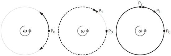
Figure 2.
Illustration of counter-propagating light waves in a rotating fiber-optic loop.
Laser gyroscopes and FOGs rely on the same fundamental physical phenomenon—the Sagnac effect, which describes how rotation induces a measurable phase shift between two optical waves propagating in opposite directions along a closed contour. When the system rotates with angular velocity Ω, the counter-propagating beams require different times to return to the initial point, which leads to a detectable nonreciprocity.
The following description provides an intuitive physical interpretation of the Sagnac effect. A rigorous derivation of the Sagnac phase shift is based on relativistic principles and can be found in the specialized literature [50,51].
The time difference Δt between the counter-propagating beams can be expressed as
where L is the length of the optical fiber, c is the speed of light, and v is the tangential velocity of the rotating loop.
The corresponding difference in optical path length ΔL for the co-propagating beam is
Since , the expression simplifies to
The resulting phase shift Δψ between the counter-propagating waves is then
where λ is the wavelength of the light source.
By substituting , which represents the tangential velocity of the rotating fiber loop at radius , and , corresponding to the optical path length of a circular loop, and introducing as the area enclosed by the fiber loop, we obtain the classical Sagnac phase expression
The classical Sagnac phase expression given in (5) is well established in the literature and forms the theoretical basis of both a ring laser and FOGs [50,51].
This expression applies to both single-turn and multi-turn fiber coils, where S represents the total effective enclosed area of all turns, physically corresponding to the area swept by the rotating optical path. The sensitivity of an FOG is therefore directly proportional to the loop area and the total fiber length. Consequently, modern trends toward miniaturization of devices that reduce both the radius and the enclosed area, thereby reducing the achievable sensitivity to the rotation and bias stability.
3. Signal Processing and Error Compensation
In spite of the FOG technology maturity and its extensive use in aviation and maritime, space, and land transportation, the devices still have a set of significant limitations associated with them. Both the intrinsic and extrinsic environmental factors and the intrinsic physical phenomena in the optical fiber control the accuracy and long-term stability of FOGs. All of these factors together create measurement noise, bias drift, and the progressive deterioration of the sensor output when used during extended autonomous operation.
3.1. Internal Noise and Bias Drift
The sources of internal noise in FOGs can be broadly divided into optical, polarization, and electronic categories.
The main noise level factors are as follows:
- RIN is fluctuations in the power of an optical source that directly affect the amplitude of the detected signal and cause bias drift.
- Backscattering and coherent spurious interference are internal reflections in a fiber coil that create phase noise and impair long-term stability.
- Rayleigh scattering is a microscopic non-uniformity in the fiber structure that forms spurious interference signals and distorts the phase.
- The Kerr effect is a nonlinear change in the refractive index at high optical powers, which causes the nonlinearity of the scaling factor and additional bias drift.
- Polarization effects are random changes in the polarization state that lead to non-recursive phase noise and non-equilibrium phase shifts.
- Intrinsic and environmental noises are thermal, vibrational, and electronic disturbances that reduce the signal stability.
These noise mechanisms collectively determine the key performance metrics of FOGs, such as the angle random walk (ARW) and bias instability, which are commonly used to quantify the sensor accuracy and long-term stability.
Even in the modern devices of navigation grade level, the bias drift is usually in the range of 0.001–0.01°/h, although in the case of strategic-grade FOGs, the level of residual drift can be as low as 10−4°/h.
The strategies of noise reduction and compensation are summarized in Table 3.
Table 3.
Methods of noise reduction and compensation.
The internal noise and bias drift of fiber-optical gyroscopes, which happen because of such phenomena as the Kerr effect, Rayleigh scattering, backscattering, and intensity noise, are proactively reduced through optical, electronic, and algorithmic measures. Modern methods allow achieving a significant improvement in the accuracy, long-term stability, and reliability, making these sensors applicable in the most challenging navigational tasks.
3.2. Influence of the External Environment
FOGs have a strong sensitivity to environmental perturbations, which is manifested in bias drift, phase noise, and poor long-term stability. The main harmful aspects include temperature variations, magnetic perturbations, ionizing radiation, mechanical stress, and humidity. In some cases, the optical path may also be affected by electromechanical effects, such as stresses resulting from the thermal expansion of metal or composite structural elements, which lead to bias errors.
To improve the accuracy and robustness, various compensatory measures are currently in development, which include design corrections, implementation of new materials, as well as the use of new digital signal-processing algorithms.
Table 4 recapitulates the most influential external factors and the effects that were caused by the corresponding compensatory actions.
Table 4.
Influential external factors and compensation approaches in FOGs.
The results presented in the table show that the modern methods are effective in reducing the effects of extrinsic perturbations; thermal and magnetic perturbation is reduced by nearly two orders of magnitude, and the use of new materials and designed structures makes them resistant to vibration- and humidity-induced perturbations.
The major determinants of the accuracy and stability of FOGs are thermal variations, magnetic fields, ionizing radiation, mechanical loading, and humidity. The contemporary compensation techniques, such as improved shielding, advanced modulation techniques, integration of new materials, and algorithmic integration, contribute greatly to the robustness of gyroscopes, thus ensuring stable operation in severe working conditions.
3.3. Compensation Methods
FOGs are enhanced in their performance by a twofold scheme of complementary compensation measures: structural (hardware-based) and algorithmic (software-based). Structural methods focus on the optical and circuit level design, and algorithmic methods make use of digital signal processing and mathematical modeling. The combination of these methodologies in a synergistic fashion is effective in reducing errors that are caused by noise, drift, and environmental effects.
The compensation methods discussed in this section are designed to suppress several fundamental noise and error mechanisms inherent to FOGs. These mechanisms include the polarization non-reciprocity arising from residual birefringence in the fiber coil, optical noise such as shot noise and relative intensity noise originating from light sources, thermally induced phase drift caused by temperature gradients, and bias instability associated with mechanical stress and environmental perturbations. Structural compensation techniques primarily address non-reciprocal physical effects and environmental sensitivities at the optical and hardware level, whereas algorithmic and signal-processing approaches focus on suppressing stochastic noise components, estimating slow-varying drifts, and compensating nonlinear error terms in the output signal. Establishing this link between compensation strategies and underlying noise sources is essential for evaluating their effectiveness under different operational conditions.
3.3.1. Structural Compensation Methods
One current trend is polarization multiplexing using two orthogonal polarization states. This method cancels noise due to polarization variations and RIN, improving the zero-bias instability from 0.1°/h to 0.0069°/h and reducing an angular random walk by a factor of 10.
Another common solution is dual-coil designs or optically compensated designs, in which anti-phase combination cancels the disturbances caused by temperature gradients and external perturbations. The results of experimental studies on zero-bias instability have shown that it can be reduced by a factor of more than five, e.g., from 0.335–0.227°/h to down to 0.061°/h [58].
Multi-point thermal compensation has even higher performance: by embedding many temperature sensors in close proximity to the coil, temperature-related drift can be countered in real time, thus enabling the use of ultra-low zero-bias instability [76].
3.3.2. Algorithmic Compensation Methods
On the software level, algorithmic compensation methods can be broadly divided into classical model-based approaches and data-driven methods. Classical algorithms, such as adaptive filters and Kalman filters, rely on explicit mathematical models of system dynamics and noise statistics [77,78,79].
In recent years, the approaches based on machine learning and neural networks are gaining more and more popularity. An up to 80% improvement in zero-bias stability has been achieved in support vector regression (SVR), attention-based long short-term memory (LSTM) networks, and hybrid algorithms, thus resolving complex nonlinear errors [80,81,82].
Additional algorithmic strategies include dual-channel noise suppression, which uses two correlated detection channels to eliminate common-mode noise, as well as optimization of the demodulation algorithm, which reduces the RIN and increases the accuracy in compact FOG systems [61]. In addition, high-frequency modulation methods have also shown effectiveness in suppressing ARW and phase noise, as indicated in [65].
Future possibilities involve modeling, optimizing temperature drifts through a multi-parameter model, with evolutionary optimization methods, in many cases, particle-swarm optimization, sometimes supplemented by models. They are especially applicable to large and high-precision systems. The installation and operational errors are additionally eliminated by systematic calibration, inclinometer sensors, and averaging methods [83,84].
Combining structural and algorithmic compensation methods allows FOGs to be very accurate and stable in a strongly noisy and adverse environmental setup. This is a holistic solution to the further development of FOG technology and its integration into the next-generation navigation systems.
Classical algorithmic methods, such as adaptive filters and Kalman filters, rely on explicit mathematical models of system dynamics and noise statistics and are distinct from the AI-based approaches discussed in the next subsection.
3.4. AI-Based Compensation and Signal Processing in FOGs
AI-based compensation represents a higher-level extension of algorithmic methods, in which data-driven models complement or augment classical signal-processing and estimation techniques.
It should be noted that AI-based approaches do not replace classical algorithms such as Kalman filtering but rather build upon them. In many practical implementations, hybrid schemes are employed, where model-based estimators provide baseline state estimation, while ML models compensate residual nonlinearities and unmodeled disturbances.
Compensation of errors can be achieved through the usage of AI with no extra sensors, e.g., LSTM models are able to completely fix any error caused by temperature only using FOG output data. Other directions of high promise are swarm-intelligence algorithms to achieve automated recalibration and hybrid methods that integrate theoretical and machine-learning algorithms and adaptive signal-decomposition algorithms that isolate dynamic errors and the underlying rotation signal.
Table 5 summarizes the key studies and presents examples of the AI-based methods and their effects on FOG accuracy and stability.
Table 5.
The most important AI-based algorithmic processes involved in error correction in FOGs.
Based on this, AI-based algorithmic approaches are currently viewed as the key path to developing FOGs that will provide higher accuracy, flexibility, and stability under complicated and dynamically changing working conditions.
4. Applications of FOG
FOGs are gradually finding applications in both fundamental and applied fields, where high-precision angular velocity and orientation measurements are required. The main properties of FOGs are long-term stability, low drift, and immunity to electromagnetic interference, which make them the preferred choice in navigation and orientation systems where traditional gyroscopes or satellite solutions are not reliable enough.
The main application domains of FOGs are illustrated in Figure 3.
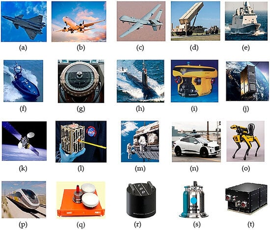
Figure 3.
Application domains for FOGs: (a) civil aviation; (b) military aviation; (c) unmanned aerial vehicle (UAV); (d) weapons and fire-control (Tomahawk); (e) surface ships; (f) unmanned surface vehicle (USV); (g) gyrocompass; (h) submarine; (i) robotic underwater vehicle (AUV/ROV); (j) earth observation satellite (EOS); (k) communicating satellite; (l) CubeSat; (m) space stations; (n) autonomous vehicle; (o) robotic; (p) rail transport. (q–t) Examples of actual FOG units and laboratory instruments: (q) geodesy and geodynamics FOG module; (r) seismological FOG sensor; (s) marine and oceanographic gyroscope; (t) astronomy and space research FOG platform.
4.1. Aviation Applications: Civil and Military
FOGs are widely used as components of inertial navigation systems (INS) in civil and military aviation. They provide highly accurate navigation and control functions, especially in situations where external signals such as GPS are unavailable or subject to interference.
The main areas of application in aviation are listed below.
4.1.1. Civil Aviation
In modern civil aviation, INS based on FOGs are used in passenger and transport aircraft to accurately determine the angular orientation, course, and position. The use of such systems increases the flight safety in case of temporary GPS failures and improves the control stability in case of turbulence, vibrations, and overloads [31].
4.1.2. Military Aviation
In military aviation, INS based on a FOG are integrated into fighter jets, helicopters, and transport aircraft. They provide reliable navigation in conditions of active interference or the unavailability of GNSS, facilitate complex maneuvers, and increase the survivability of equipment in conditions of electronic warfare [89,90].
4.1.3. Unmanned Aerial Vehicles (UAVs)
FOGs are increasingly being used in both military and civilian unmanned aerial vehicles. Their use ensures autonomy in areas where GPS is suppressed, as well as immunity to interference, and increases the accuracy of stabilizing the payload of cameras, LiDAR systems, and communication channels. For strategic and reconnaissance UAVs, inertial systems based on FOGs are key for reliable mission performance in conditions of a polluted or inaccessible GNSS signal [91,92,93,94].
Navigation and tactical-grade FOGs used in aviation and UAV inertial navigation systems demonstrate bias instability in the range of 0.0014–0.1°/h, depending on the system class and level of compensation. In particular, navigation-grade IFOG-based systems have reported bias instability as low as 0.0014–0.0017°/h and angular random walk on the order of 0.0038°/√h, satisfying stringent aircraft navigation requirements such as FAA RNP-10. Simulation studies indicate that up to 95% of long-range transoceanic flights relying solely on FOG based inertial navigation achieve terminal position errors within ±10 nautical miles (≈18.5 km), demonstrating the suitability of FOGs for GNSS-denied and interference-prone aerial missions [95,96].
4.1.4. Weapons and Fire Control
FOGs are widely used in weapon guidance and stabilization systems for electro-optical systems. They are part of tactical missile control systems and sighting containers of airplanes and helicopters, where high autonomy and resistance to electronic countermeasures are required [96]. The main advantages of FOGs include high accuracy, fault tolerance, and the ability to maintain stable operation in the face of vibrations, shock loads, and electromagnetic influences [97,98].
FOGs are now an integral part of modern INSs, providing accurate and reliable navigation for civilian, military, and unmanned platforms. Their resistance to electromagnetic interference and the ability to work without GPS make FOGs one of the basic technologies of modern aviation.
4.2. Maritime and Submarine Applications
FOGs are one of the main elements of marine and underwater navigation systems, where GNSS satellite navigation is often unavailable or insufficiently reliable. Due to its solid-state design, high measurement accuracy, and resistance to adverse environmental conditions, FOGs are well suited for various marine applications.
4.2.1. Surface Ships
Inertial navigation systems based on FOGs are widely used in both military and civilian vessels to determine the course, roll, and angular orientation. Such systems function reliably under rolling, vibration, and dynamic loads and are also often used as backup navigation devices, increasing the overall safety of navigation [99].
Compared with mechanical gyroscopes, FOGs provide higher and longer-term stability, moreover, lower sensitivity to magnetic disturbances, which is especially important for offshore platforms operating in polar and equatorial latitudes [100].
4.2.2. Gyrocompasses
Modern gyrocompasses based on FOGs provide fast and autonomous determination of the true north and spatial orientation of the vessel (roll, pitch, and yaw) without moving parts, which guarantees high reliability and long-term stability. Due to its solid-state design and resistance to vibrations and magnetic influences, gyrocompasses are increasingly used in long-term marine missions [101,102,103].
4.2.3. Submarine and Underwater Vehicles
Long-term autonomous navigation on both nuclear and diesel–electric submarines is based on inertial navigation systems based on FOGs, providing accurate course and position determination even in the prolonged absence of GNSS signals. Such systems are capable of maintaining stable operation for weeks and even months underwater, ensuring mission reliability [101,103].
In marine and underwater navigation systems, inertial navigation devices based on FOGs ensure stable long-term operation under dynamic operating conditions. Tactical and navigation grade FOGs employed in ship and AUV strapdown inertial navigation systems typically exhibit bias drift in the range of 0.01–0.1°/h. Practical implementations report a heading accuracy on the order of 0.2°, which can be further improved to approximately 0.04° through calibration and advanced compensation techniques. Such performance enables reliable navigation during extended underwater missions in the absence of GNSS [104,105,106].
FOGs also play a key role in the navigation and control of autonomous and remotely operated underwater vehicles (AUVs and ROVs). They provide accurate course tracking and load stabilization during oceanographic surveys, seabed mapping, and search and rescue operations, where traditional navigation devices are ineffective [107,108]. Recent advances in the miniaturization of FOGs, increased energy efficiency, and the use of silicon photonics have expanded the depth and duration of autonomous underwater missions [109].
4.2.4. Unmanned Surface Vehicles (USVs)
FOGs are increasingly being used in modern unmanned surface vehicles to ensure accurate and GPS-independent navigation. Their resistance to electronic interference and the ability for long-term autonomous operation make them the optimal solution for complex maritime missions, including surveillance, mapping, and environmental monitoring [110]. FOG-based navigation systems provide highly accurate positioning and motion control on various types of offshore platforms, from surface vessels to deep-sea research vehicles. Their independence from GNSS signals and high resistance to external influences make such systems especially effective in environments where traditional navigation technologies are losing reliability.
4.3. Fiber-Optic Gyroscopes in Spacecraft
In modern space technology, FOGs have become the preferred solution for orientation and stabilization systems, gradually replacing mechanical and laser gyroscopes. Operating in microgravity and thermal extremes, they provide the exceptional accuracy and long-term stability needed for spacecraft navigation and control [111].
4.3.1. Earth-Orbiting Missions
FOGs are widely used in Earth observation, communications, and navigation satellites, as well as in small spacecraft. In observation satellites, they provide high precision guidance of optical payloads, allowing images to be obtained with a resolution of up to a submeter level [112]. In communications and navigation satellites, inertial units based on FOGs maintain the orbital position and orientation of the antennas, ensuring the continuity of communication [113]. Compact FOG-INS architectures are also integrated into CubeSat satellites and microsatellites, providing autonomous orientation control even without magnetometers and external sensors [114].
4.3.2. Crewed Spacecraft and Space Stations
On the International Space Station and manned spacecraft, FOGs are used for precise orientation control and docking [112]. Their low drift and high stability ensure precise maneuvers and orientation during long-term flights into deep space [115].
FOGs are a key element of space navigation systems today. Their high accuracy, GNSS independence, and radiation resistance make them indispensable for orientation and stabilization systems for satellites and orbital stations.
4.4. Fiber-Optic Gyroscopes in Ground Platforms
FOGs play an important role in navigation and control systems for ground vehicles operating under conditions of high loads, vibrations, and lack of GNSS signals. Their independence from external signals and high accuracy make them a key component of modern ground-based platforms in both the defense and civilian sectors.
4.4.1. Military and Defense Applications
Inertial systems based on FOGs are integrated into armored vehicles, artillery installations, and other combat vehicles to provide accurate course and orientation data when driving over rough terrain and in conditions of active interference. They support weapon stabilization and fire control systems, increasing guidance accuracy and ensuring reliable maneuvering even in conditions of electronic warfare [116].
4.4.2. Autonomous and Robotic Systems
In civil transport, FOGs are part of driver assistance and autonomous navigation systems, complementing information from LiDAR sensors, cameras, and GNSS receivers [117]. They provide stable navigation in conditions of the limited reception of satellite signals—in tunnels, urban canyons, or underground parking lots, increasing overall traffic safety [118,119].
FOGs are also widely used in logistics robots, search and rescue, and industrial systems, providing precise motion control and orientation even with vibrations and uneven surfaces. In railway transport, including high-speed trains, gyroscopes are used in stabilization and automatic control systems, maintaining accurate positioning in the absence of satellite navigation signals [120].
FOGs have become a key technology for ground-based navigation and control systems, covering a wide range of military and civilian applications, from combat vehicles to autonomous robots and rail transport. High precision, vibration resistance, and GNSS independence ensure reliable operation in environments where traditional technologies often prove ineffective.
4.5. Scientific Research (Geodesy and Seismology)
FOGs are gradually finding applications in both basic and practical fields of application requiring the high-precision of measurements of rotation, orientation, and motion. Their unique characteristics of stability over long durations, low drift, and resistance to electromagnetic interference makes them indispensable in situations where the traditional gyroscopes or satellite navigation fail. The key areas of implementation are as follows.
4.5.1. Geodesy and Geodynamics
FOGs are used to measure the rotation of the earth, the tidal waves, and movements of the earth. In large observatories (e.g., in Germany and Italy), rotational seismometry is performed using RLGs rather than FOGs. These measurements are used to supplement GPS measurements and improve the accuracy of geodynamic models of the globe.
In addition, recent studies have shown the potential of using FOGs to measure gravity gradients, where changes in the local gravitational field are converted into rotational motion using two-mass or interferometric designs based on the Sagnac effect [28,29,30]. This new direction provides additional parameters for geophysical monitoring, allowing recording weak density variations in the Earth’s interior and increasing the accuracy of gravimetric and geodynamic observations.
4.5.2. Seismology
The angular fluctuations of the ground that occur during earthquakes can be recorded using FOG, while traditional accelerometers do not have this capability. An example is the ROMY project (Ring Laser Gyroscope, Germany), which demonstrates the use of large-scale rotational seismometers [121].
4.5.3. Oceanography and Other Scientific Domains
In marine geophysics, FOGs are integrated into research underwater platforms, providing stable navigation during long-term oceanographic expeditions and high-precision mapping of the seabed, including tectonically active zones. Their ability to capture the slightest rotational movements makes them a valuable tool for studying underwater seismic activity and monitoring the dynamics of the oceanic crust [122,123].
In addition to geodesy and seismology, high-precision FOGs are also used in astronomical observatories to stabilize platforms and accurately point telescopes at celestial objects [31]. The high sensitivity of FOGs to angular fluctuations opens up new possibilities for observing geodynamic and astrophysical processes, as well as for expanding our knowledge of the Earth and the universe.
A summary of the main application domains of FOGs, together with representative platforms and references, is provided in Table 6.
Table 6.
Summary of major application domains of FOGs.
5. Future Trends
Subsequent advances in inertial navigation are driven by the continued miniaturization and the emergence of new photonic and material platforms, the smooth coupling of FOGs with microelectromechanical systems, light detection and ranging systems, and quantum sensors. At the same time, AI algorithms have become powerful resources to work with the adaptive error-correction and data fusion. Taken together, these converging trends point to a change in direction to hybrid, intelligent, and quantum-enhanced navigation systems.
In addition to short-term environmental influences, the long-term stability and lifetime performance of FOGs are critical factors for aerospace, marine, and scientific missions. Aging-related effects in FOGs may arise from gradual changes in fiber properties, degradation of optical sources and detectors, drift of electronic components, and the long-term accumulation of thermo-mechanical stress in the fiber coil. These processes can lead to slow variations in bias, scale factor, and noise characteristics over extended operational periods.
To mitigate aging and long-term drift, modern FOG systems employ strategies such as periodic calibration, redundant sensing channels, temperature stabilization, and long-term bias monitoring combined with adaptive compensation algorithms. While FOGs generally demonstrate superior lifetime stability compared to mechanical gyroscopes, ensuring consistent performance over years of operation remains an important research and engineering challenge, particularly for autonomous and maintenance-limited platforms.
5.1. Miniaturization and Integration
One of the major trends in the development of FOGs is the miniaturization of gyroscopes. The main goal is to reduce the size, weight, and cost without affecting, and possibly increasing, the accuracy of measurements. Recent advances in integrated general and silicon photonics have enabled the realization of small-sized FOGs with linear dimensions of 30–50 mm, with bias stabilities corresponding to the tactical-grade criteria of better than 0.5°/h and nearly matching the navigation-grade performance of better than 0.039°/h [124,125]. These designs simplify the processes of assembly, increase the efficiency of manufacturing, and reduce the cost of production, expanding the range of areas where FOGs may be used to a larger number of application areas.
However, there are technical challenges that arise as a result of the miniaturization process. With the reduced size of the device, the non-reciprocity of polarization, polarization distortions of magneto-optical distortion, and parasitic reflections are sensitivity factors that deteriorate the accuracy at smaller device sizes. Photonic-crystal fibers (PCFs), optimized coil geometries, and refined optical-integration schemes are used to reduce these effects. These solutions allow compact FOGs to achieve the same accuracy as larger scale systems and, at the same time, reduce the reliance on large-scale magnetic shielding and, hence, the cost of the system as a whole [126,127].
In miniaturized FOGs, the polarization non-reciprocity becomes more pronounced due to the increased sensitivity to residual birefringence, mechanical stress, and temperature gradients in tightly wound fiber coils. PCFs mitigate these effects by providing a highly symmetric core structure with significantly reduced temperature-dependent birefringence compared to conventional polarization-maintaining fibers, leading to the improved thermal stability of the bias. In addition, optimized coil geometries, such as symmetric and multi-pole winding schemes, distribute thermo-mechanical stresses more uniformly along the fiber path, thereby suppressing non-reciprocal phase errors and reducing bias drift, even in compact coil configurations [128,129,130,131].
Therefore, the data show that it is possible to achieve high accuracy and low cost at the same time by the means of the sophisticated design and implementation of the newest materials and integration methods. The trend is a key milestone towards the broad acceptance of FOGs in unmanned and robotics, as well as portable navigation systems.
To ensure a systematic discussion of the strengths, weaknesses, opportunities and threats associated with miniaturization of FOGs, a special SWOT analysis on compactness is presented in Table 7.
Table 7.
SWOT analysis of compactness in FOGs.
Compactness is a key parameter for the further evolution of FOGs. The viability of centimeter-scale devices with tactical-grade stability has already been demonstrated by integrated photonics. The main benefits include reductions in size, weight, and power consumption, as well as the potential for mass production. On the other hand, miniaturization entails certain drawbacks, such as increased noise levels, optical reflections, and higher environmental sensitivity. Opportunities are linked to UAVs, aerospace, and defense, while threats are associated with competition from MEMS and current manufacturing limitations. Ultimately, the balance between size and measurement precision will determine the future success of FOG technology.
5.2. Next-Generation Materials and Optics
Gyroscopes based on FOGs are currently being extensively developed courtesy of the new materials and optical elements. The main aim of this study is to enhance the accuracy and reliability and, on the other hand, lower the size and cost of the devices.
The main areas of advancement are as follows:
Photonic crystal fibers—with reduced losses and noise rates as well as high sensitivity in comparison to conventional fibers. This makes them good prospects of high-precision and space [138].
Silicon photonics—the merging of optical circuits onto chips of fingertip size. They consist of solutions that decrease the mass and size of the gyroscopes and still provide accuracy at the tactical level. Silicon waveguides with high-contrast offer a high level of polarization and electro-optical efficiency, but the issue of optical reflections is challenging.
Broadband sources and multi-frequency interference—allowing simplification of resonator FOG architectures and eliminating laser noise and thus providing navigation grade accuracy with very little design complexity [139].
New types of coating and integrated polarizers—tilted fiber Bragg gratings, which enhance the thermal stability of the coil and increase its mechanical flexibility, make gyroscopes smaller and less susceptible to external factors [140].
Therefore, the solution to the further development of FOGs is the use of next-generation materials and integrated optics, which will allow combining high precision, compactness, and strength in the demanding operating conditions.
5.3. Integration with Other Sensors
One of the key areas of modern inertial navigation research is the integration of FOGs with additional sensors to compensate for individual limitations and improve overall accuracy. Combining optical, mechanical, and visual modalities ensures stable navigation, insensitive to external interference and drift.
Integration with MEMS: Compact hybrid units combining FOGs with MEMS accelerometers and gyroscopes provide an optimal balance between long-term stability and low power consumption [141]. MEMS sensors are prone to drift, but they provide high short-term sensitivity, which effectively complements the data of FOGs during dynamic maneuvers and the absence of a GNSS signal [142,143].
Cameras and Vision Systems: Combining the data of FOGs with visual tracking systems increases the accuracy of localization in difficult or low-textural conditions. Cameras provide relative movement, and FOGs maintain orientation. Experiments show that hybrid visual–inertial systems reduce the tracking error by more than 5% with lower computational costs [144].
LiDAR and Multisensor Complexes: The integration of FOGs with LiDAR systems allows for high-precision 3D mapping and orientation determination in the absence of GPS or poor visibility. LiDAR provides spatial perception, whereas a FOG provides stable rotation data for filtering algorithms (for example, the expanded and uncut Kalman filter). This combination is especially important for autonomous transportation and marine systems [145].
Quantum-Enhanced Sensors: A promising direction is the hybridization of FOGs with quantum sensors, in particular, atomic interferometers and compressed light gyroscopes, which are capable of surpassing classical sensitivity limits. Unlike traditional optical circuits, quantum sensors use phase correlations in entangled photonic or atomic states to suppress gunshot noise [146].
The interface between classical FOGs and quantum sensors requires synchronous data integration with consistent integration times: short-window quantum measurements (milliseconds) correct for high-frequency noise, and FOG averaging ensures long-term stability. The optimal mixing mode is implemented by adaptive filters or Bayesian estimators, which dynamically change the weight of each source in terms of accuracy and frequency band. Such architectures are still at the experimental stage, but they promise significant improvements in stability and drift [147].
Data Fusion Algorithms: Advanced processing techniques and AI remain critical for the integration of multisensory data. Modern algorithms reduce the internal noise of an FOG by up to 16 times and the instability of zero by almost an order of magnitude using adaptive Kalman filtering and neural network models [148]. The integration of the FOG with MEMS, LiDAR, and quantum sensors forms the basis of a new era of intelligent self-calibrating navigation systems with high accuracy and reliability.
5.4. Algorithmic Innovations
The recent developments of FOGs cannot be discussed without reference to the use of AI methods and adaptive signal-processing methods. The methodological innovations are used to effectively suppress the complex sources of error, which include the temperature drift, dynamic vibrations, and instability of calibration.
The application of AI can provide the compensation of errors without resorting to additional sensors; in particular, LSTM networks have succeeded in eliminating temperature-related perturbations using only FOG output data. Other promising methods include swarm-intelligence algorithms to develop autonomous recalibration, hybrid models to integrate theoretical models with machine learning models, and adaptive signal-decomposition methods that are able to separate the dynamic perturbations of the true rotational signal.
A summary of AI-based algorithmic methods for error compensation in FOGs, including neural networks, swarm intelligence approaches, and adaptive signal decomposition techniques, is provided in Table 8.
Table 8.
Key AI-based algorithmic methods for error compensation in FOGs.
In turn, AI-inspired algorithmic solutions represent an essential trend in the development of FOG technology, enabling higher accuracy, flexibility, and robustness under challenging and dynamically changing operational conditions, as summarized by the methods listed in Table 7.
The discussed trends in Section 5.1, Section 5.2, Section 5.3 and Section 5.4 highlight not only the ongoing technological progress of FOGs but also the strategic strengths, inherent limitations, and external factors that collectively shape their future development. The overall, SWOT analysis presented in Figure 4 provides a structured perspective on the long-term evolution and competitiveness of FOG technology.

Figure 4.
SWOT analysis of FOGs—graphical representation.
5.5. Overall SWOT Analysis of FOG Technology
Figure 4 summarizes the overall SWOT framework of the FOG technology, highlighting both its technological maturity and the challenges associated with further development. The main strengths of FOGs include high accuracy and long-term stability, solid-state design without moving parts, and strong resistance to vibration and harsh operating environments, which make them a competitive alternative to classical RLGs in high-end navigation systems. At the same time, weaknesses remain, primarily related to sensitivity to temperature and mechanical stress, increased bias drift in miniaturized designs, higher cost compared to MEMS gyroscopes, and the complexity of optical integration.
From a strategic perspective, significant opportunities arise from advances in integrated photonics, chip-scale FOG concepts, and AI-based error compensation, as well as from growing demand in UAVs, robotics, autonomous systems, and space applications. However, FOG technology also faces notable threats, including rapid progress in low-cost MEMS gyroscopes, competition from alternative navigation technologies in GNSS environments, manufacturing challenges associated with photonic integration, and market limitations.
Within this broader SWOT framework, compactness represents a critical cross-cutting factor. Therefore, a detailed SWOT analysis of miniaturization is provided separately in Table 8, illustrating how the general strengths, weaknesses, opportunities, and threats of FOG technology manifest specifically in compact and integrated implementations.
As a concluding of this section, Figure 4 illustrates how the technological advances discussed in Section 5 shape the strategic position of FOG technology. While miniaturization, integrated photonics, multisensor fusion, and AI algorithms significantly enhance the performance and applicability of FOGs, their further development remains constrained by cost, integration complexity, and competition from alternative sensing technologies. This SWOT perspective highlights the key factors that will ultimately determine the future adoption and evolution of FOG navigation systems.
6. FOG and Competing Gyroscope Technologies
FOGs continue to compete with other inertial rotation measurement technologies. Among them, microelectromechanical gyroscopes (MEMS) occupy the low budget segment, while hemispherical resonator gyroscopes (HRG)—for example, Safran HRG CrystalTM (Paris, France) —determine the high-precision level. Other types (RLG, DTG, VSG) remain in use in legacy or intermediate systems but are gradually being replaced by optical and hybrid solutions.
6.1. FOG vs. MEMS
Recent studies published between 2023 and 2025 [149,150,151] indicate that MEMS gyroscopes have significantly improved their performance, with reported bias instability below 0.1°/h in laboratory demonstrations and selected commercial-grade prototypes. These advances are primarily driven by improved resonator design, temperature compensation, and integrated electronics. Nevertheless, maintaining such performance under wide temperature ranges and long-term operation remains a key challenge for MEMS inertial navigation systems.
6.2. FOG vs. HRG
Recent publications (2023–2025) confirm that HRGs remain the benchmark solid-state technology for strategic and navigation-grade inertial systems. Modern HRGs, such as Safran’s HRG Crystal™, meet and exceed strategic requirements, enabling autonomous navigation performance on the order of 0.5 nautical miles over 120 h in demanding maritime and military applications. This performance is achieved through a combination of high structural symmetry, trimming techniques, whole-angle operation, standing-wave control, and advanced vibration and time-division multiplexing schemes [152,153].
To summarize the main differences between the leading types of gyroscopes, Table 9 provides a comparison of their characteristics.
Table 9.
Comparative review of gyroscope technologies and market positioning.
As can be seen from Table 9, the cost is inversely proportional to the accuracy: increasing the stability increases the price by an order of magnitude by about 5–10 times, which determines the division of the market into three categories—cheap (MEMS), medium (FOG), and high-precision (HRG) segments.
Beyond accuracy metrics, the practical deployment of gyroscope technologies is strongly influenced by system-level factors such as cost, architectural complexity, power consumption, and integration effort. MEMS gyroscopes offer clear advantages in terms of low cost, low power consumption, and ease of large-scale integration, which explains their widespread adoption in consumer and automotive applications. However, these benefits are typically achieved at the expense of long-term stability and bias performance, particularly under wide temperature variations.
In contrast, HRGs provide exceptional long-term stability and ultra-low drift, but their practical use is constrained by high manufacturing complexity, stringent fabrication tolerances, and significantly higher cost. FOGs occupy an intermediate and often optimal position, offering a balanced trade-off between accuracy, robustness, system complexity, and cost. Although FOGs generally require more complex optical and electronic subsystems than MEMS solutions, their solid-state design, moderate power consumption, and scalability make them well suited for aerospace, marine, and defense applications where reliability and long-term stability are critical.
6.3. FOG vs. Quantum Technologies
To date, no mass-produced optical gyroscope has reached the quantum noise limit (SQL). Experimental approaches such as compressed light and atomic interferometers still have a noise level several orders of magnitude higher than the best classical FOGs [154,155]. Nevertheless, quantum research is important for finding alternative measurement principles. Although current prototypes are far from practical applications, hybrid quantum–classical FOGs may open up new limits of sensitivity in the future after eliminating the problems of photon loss and decoherence.
In conclusion, FOGs currently occupy the middle- and high-precision range among all rotation measurement technologies, providing an optimal balance between accuracy, reliability, and cost. MEMS gyroscopes are the leaders in the low-budget segment, while HRG defines the strategic and space level; however, FOGs remain the most scalable and versatile solution for aviation, navy, and defense systems. Quantum approaches are still at the laboratory stage, but further research can combine classical and quantum principles, laying the foundation for a new generation of hybrid inertial systems.
7. Perspectives and Outlook
FOGs have reached a mature stage of development but remain at the center of innovation in the field of inertial navigation. In the next decade, their evolution will be determined by three key factors—integrated photonics, AI-based error compensation algorithms, and the increasing need for autonomous navigation amid GNSS vulnerability [156,157].
The next generation of compact and energy-efficient FOGs, including chip-scale and resonator designs, will be developed thanks to silicon photonics and new materials—hollow and photonic-crystalline fibers. These technologies will allow maintaining tactical accuracy with centimeter dimensions and will provide wide application in robotics, UAVs, and marine and space platforms. From a market point of view, steady growth (about 5–10% CAGR) is expected until the early 2030s, mainly due to defense programs, autonomous marine systems, and land-based robots [158,159]. As the cost decreases and production scales up, FOGs increasingly occupy an intermediate niche between low-cost MEMS systems and high-precision HRGS.
In general, the future of FOGs lies in miniature, intelligent, and hybrid architectures combining optical precision and the adaptability of AI. Further research in integrated optics, noise reduction, and self-calibration will ensure FOGs have a stable place in the next generation of inertial and navigation systems for aviation, defense, and science.
8. Conclusions
The development of FOGs has become one of the key technological achievements in modern inertial navigation. From early experimental prototypes, FOGs have evolved into advanced architectures, including IFOG, DFOG, RFOG, and HFOG configurations, each offering specific advantages in terms of accuracy, stability, and robustness. These technologies are now widely applied in aviation, marine and underwater navigation, space missions, ground platforms, and scientific instrumentation. Continuous progress in optical components, noise suppression, and digital signal-processing techniques has led to steady improvements in overall system performance.
Beyond summarizing the existing research results, this review provides a systematic and integrated perspective on the current state and future evolution of FOG technology. In contrast to previous surveys that typically focused on individual FOG architectures or isolated error sources, this work jointly analyzes modern FOG designs, advanced signal-processing and AI-driven compensation methods, and emerging trends in multisensor fusion within a unified framework. Such an integrative approach highlights the transition of classical inertial navigation systems using FOGs toward intelligent, adaptive, and hybrid sensing platforms.
Furthermore, the comparative analysis with competing technologies, including RLGs, MEMS gyroscopes, HRGs, and emerging quantum sensors, clarifies the unique positioning of FOGs in terms of their accuracy, long-term stability, scalability, and cost. At the same time, this review identifies several open research challenges, such as the trade-off between miniaturization and bias stability, the robustness and generalization of AI-based compensation under varying operational conditions, and the evolving competition with rapidly advancing MEMS and HRG technologies.
Looking forward, the future development of FOGs is closely linked to continued miniaturization, deeper integration with MEMS and complementary sensors, advances in photonic materials and integrated optics, and the wider adoption of adaptive data-driven error compensation algorithms. These converging trends are expected to further strengthen the competitiveness of FOG technology and enable its broader deployment in unmanned platforms, autonomous robotics, and navigation scenarios where GNSS signals are unavailable or unreliable.
Author Contributions
Conceptualization, N.S. and D.N.; methodology, Y.T.; validation, Y.T., N.S., and A.S.; resources, A.S., Y.N., and Y.M.; writing—original draft preparation, D.N.; writing—review and editing, N.S. and Y.N.; visualization, Y.M., A.B., and N.K.; supervision, A.B. and N.K.; funding acquisition, Y.T. All authors have read and agreed to the published version of the manuscript.
Funding
This research was funded by the Ministry of Science and Higher Education of the Republic of Kazakhstan (Grant No. AP26104843).
Institutional Review Board Statement
Not applicable.
Informed Consent Statement
Not applicable.
Data Availability Statement
No new data were created or analyzed in this study. Data sharing is not applicable to this article.
Acknowledgments
We would like to express our sincere appreciation to Zhandos Dosbayev for his valuable assistance during the revision of the manuscript, particularly for his help in improving the clarity and readability of the final version.
Conflicts of Interest
The authors declare no conflicts of interest.
Abbreviations
The following abbreviations are used in this manuscript:
| FOG | Fiber-Optic Gyroscope |
| IFOG | Interferometric Fiber-Optic Gyroscope |
| RFOG | Resonant Fiber-Optic Gyroscope |
| DFOG | Digital Fiber-Optic Gyroscope |
| HFOG | Hybrid Fiber-Optic Gyroscope |
| INS | Inertial Navigation System |
| GNSS | Global Navigation Satellite System |
| GPS | Global Positioning System |
| MEMS | Micro-Electro-Mechanical System |
| RLG | Ring Laser Gyroscope |
| HRG | Hemispherical Resonator Gyroscope |
| VSG | Vibrating-Structure Gyroscope |
| DTG | Dynamically Tuned Gyroscope |
| SWaP-C | Size, Weight, Power, and Cost |
| UAV | Unmanned Aerial Vehicle |
| AUV | Autonomous Underwater Vehicle |
| UUV | Unmanned Underwater Vehicle |
| AGV | Automated Guided Vehicle |
| AMR | Autonomous Mobile Robot |
| SiPhOG | Silicon Photonics Gyroscope |
| PIC | Photonic Integrated Circuit |
| AI | Artificial Intelligence |
| ARW | Angular Random Walk |
| CEEMDAN | Complete Ensemble Empirical Mode Decomposition with Adaptive Noise |
| NAFSA | Novel Adaptive Firefly Swarm Algorithm |
| LSTM | Long Short-Term Memory |
| SVR | Support Vector Regression |
| MIOC | Multifunction Integrated Optical Chip |
References
- Xu, H.; Wang, L.; Zu, Y.; Gou, W.; Hu, Y. Application and Development of Fiber Optic Gyroscope Inertial Navigation System in Underground Space. Sensors 2023, 23, 5627. [Google Scholar] [CrossRef]
- Sanders, G.A.; Szafraniec, B.; Liu, R.-Y.; Laskoskie, C.L.; Strandjord, L.K.; Weed, G. Fiber optic gyros for space, marine, and aviation applications. In Proceedings of the Fiber Optic Gyros: 20th Anniversary Conference, Denver, CO, USA, 12 November 1996; SPIE: Bellingham, WA, USA, 1996; Volume 2837, pp. 61–71. [Google Scholar] [CrossRef]
- Fink, M.; Steinlechner, F.; Handsteiner, J.; Dowling, J.P.; Scheidl, T.; Ursin, R. Entanglement-enhanced optical gyroscope. New J. Phys. 2019, 21, 053010. [Google Scholar] [CrossRef]
- Vali, V.; Shorthill, R.W. Fiber ring interferometer. Appl. Opt. 1976, 15, 1099–1100. [Google Scholar] [CrossRef]
- Lefèvre, H.C. The fiber-optic gyroscope: Achievement and perspective. Gyroscopy Navig. 2012, 3, 223–226. [Google Scholar] [CrossRef]
- Karagöz, E.; Aşık, F.Y.; Gökkavas, M.; Akbaş, E.E.; Yertutanol, A.; Özbay, E.; Özcan, Ş. Reduction in Temperature-Dependent Fiber-Optic Gyroscope Bias Drift by Using Multifunctional Integrated Optical Chip Fabricated on Pre-Annealed LiNbO3. Photonics 2024, 11, 1057. [Google Scholar] [CrossRef]
- Radoš, K.; Brkić, M.; Begušić, D. Recent Advances on Jamming and Spoofing Detection in GNSS. Sensors 2024, 24, 4210. [Google Scholar] [CrossRef]
- Bergh, R.A.; Arnesen, L.; Herdman, C. Fiber optic gyro development at Fibernetics. In Proceedings of the Fiber Optic Sensors and Applications XIII, Baltimore, MD, USA, 12 April 2016; SPIE: Bellingham, WA, USA, 2016; Volume 9852, pp. 90–108. [Google Scholar]
- Mahudapathi, S.; Sumukh Nandan, R.; Gowrishankar, R.; Srinivasan, B. The Challenges and Opportunities for Performance Enhancement in Resonant Fiber Optic Gyroscopes. Sensors 2025, 25, 223. [Google Scholar] [CrossRef] [PubMed]
- Felux, M.; Fol, P.; Figuet, B.; Waltert, M.; Olive, X. Impacts of Global Navigation Satellite System Jamming on Aviation. NAVIGATION J. Inst. Navig. 2024, 71, navi.657. [Google Scholar] [CrossRef]
- Felux, M.; Figuet, B.; Waltert, M.; Fol, P.; Strohmeier, M.; Olive, X. Analysis of GNSS disruptions in European Airspace. In Proceedings of the 2023 International Technical Meeting of The Institute of Navigation, Long Beach, CA, USA, 24–26 January 2023; pp. 315–326. [Google Scholar] [CrossRef]
- Novák, A.; Kováčiková, K.; Kandera, B.; Sedláčková, A.N. Global Navigation Satellite Systems Signal Vulnerabilities in Unmanned Aerial Vehicle Operations: Impact of Affordable Software-Defined Radio. Drones 2024, 8, 109. [Google Scholar] [CrossRef]
- Liu, Y.; Jin, J.; Liu, Y.; Hu, H.; Chen, X. An Ultrasimplified Two-Axis Interferometric Fiber Optic Gyroscope with Multifunctional Integrated Optics Circuit Sharing. J. Light. Technol. 2025, 43, 6939–6947. [Google Scholar] [CrossRef]
- Huang, H.; Wang, W.; Zhu, L.; Shi, F.; Cao, X.; Chen, Y.; Li, Z. An Interferometric Fiber Optic Gyroscope Based on Fiber Delay with Reduced Bias Instability and Enhanced Sensitivity. J. Light. Technol. 2025, 43, 4290–4297. [Google Scholar] [CrossRef]
- Menéndez, R. IFOG and IORG Gyros: A Study of Comparative Performance. In Gyroscopes-Principles and Applications; IntechOpen: London, UK, 2019. [Google Scholar] [CrossRef]
- Hu, J.; Li, B.; Liu, S.; Ma, H. Sensitivity analysis and comparison of broadband source-driven resonant fiber-optic gyroscopes. Appl. Opt. 2025, 64, 3974–3979. [Google Scholar] [CrossRef]
- Nasiri-Avanaki, M.; Soleimani, V.; Mazrae-Khoshki, R. Comparative Assessment on the Performance of Open-Loop and Closed-Loop IFOGs. Opt. Photonics J. 2012, 2, 17–29. [Google Scholar] [CrossRef]
- Sanders, G.; Taranta, A.; Narayanan, C.; Fokoua, E.; Mousavi, A.; Strandjord, L.; Smiciklas, M.; Bradley, T.; Hayes, J.; Jasion, G.; et al. Hollow-core resonator fiber optic gyroscope using nodeless anti-resonant fiber. Opt. Lett. 2020, 46, 46–49. [Google Scholar] [CrossRef]
- Zhu, L.; Wang, W.; Shi, F.; Cao, X.; Chen, Y.; Huang, H.; Cao, Y.; Zhang, D.; Li, Z. Development of a High-Performance Rotational Seismometer Based on the Dual-Channel Fiber Optic Gyroscope. J. Light. Technol. 2024, 42, 8951–8958. [Google Scholar] [CrossRef]
- Cao, Y.; Ma, X.; Chen, Y.; Huang, H.; Zhu, L.; Wang, W.; He, Y.; Li, Z. Interferometric fiber-optic gyroscope based on mode-division multiplexing. Opt. Lett. 2023, 48, 3067–3070. [Google Scholar] [CrossRef]
- Cao, Y.; Zhu, L.; Shi, F.; Chen, Y.; Cao, X.; Wang, W.; Huang, H.; Ma, X.; Li, Z. Dual-polarization interferometric fiber optic gyroscope with Shupe effect compensation. Appl. Phys. Lett. 2023, 123, 011104. [Google Scholar] [CrossRef]
- Wang, W.; Zhu, L.; He, Y.; Chen, Y.; Huang, H.; Cao, X.; Shi, F.; Li, Z. Sensitivity-enhanced fiber optic gyroscope for rotational seismology. In Proceedings of the Advanced Fiber Laser Conference (AFL2023), Shenzhen, China, 18 March 2024; SPIE: Bellingham, WA, USA, 2024; Volume 13104, pp. 789–793. [Google Scholar] [CrossRef]
- Wang, W.; Shi, F.; Cao, X.; Zhou, Z.; Zhu, L.; Huang, H.; He, Y.; Chen, Y.; Li, Z. Enhanced Sensitivity in Fiber Optic Gyroscopes Achieved Through Dual-Channel Improved Cooperative Modulation. IEEE Sens. J. 2025, 25, 9655–9663. [Google Scholar] [CrossRef]
- He, D.; Cao, Y.; Zhou, T.; Peng, C.; Li, Z. Sensitivity enhancement through RIN suppression in dual-polarization fiber optic gyroscopes for rotational seismology. Opt. Express 2020, 28, 34717–34729. [Google Scholar] [CrossRef]
- Huang, H.; Cao, Y.; Zhu, L.; Chen, Y.; Wang, W.; Shi, F.; Cao, X.; Li, Z. A High-Sensitivity Giant Interferometric Fiberoptic Gyroscope for Seismic Observation. J. Light. Technol. 2025, 43, 869–878. [Google Scholar] [CrossRef]
- Jaroszewicz, L.R.; Kurzych, A.; Krajewski, Z.; Dudek, M.; Kowalski, J.K.; Teisseyre, K.P. The Fiber-Optic Rotational Seismograph—Laboratory Tests and Field Application. Sensors 2019, 19, 2699. [Google Scholar] [CrossRef]
- Chen, C.; Wan, W.; Jian, Y.; Zhang, D.; Zhu, L.; Song, Y.; Feng, W.; Wang, Y. Performance Evaluation of Rotational Seismometers: Noise Characterization and Comparative Analysis. Seismol. Res. Lett. 2025, 96, 2957–2967. [Google Scholar] [CrossRef]
- Chen, Y.; Zhu, L.; Wang, W.; He, Y.; Cao, Y.; Huang, H.; Ma, X.; Li, Z. A structure based on fiber optic gyroscopes for gravity measurement. In Proceedings of the Advanced Optical Manufacturing Technologies and Applications 2022; and 2nd International Forum of Young Scientists on Advanced Optical Manufacturing (AOMTA and YSAOM 2022), Changchun, China, 9 January 2023; SPIE: Bellingham, WA, USA, 2023; Volume 12507, pp. 7–10. [Google Scholar] [CrossRef]
- Chen, Y.; Wang, W.; Zhu, L.; Shi, F.; He, Y.; Huang, H.; Li, Z. Development of a gravity measurement system based on fiber-optic gyroscope. Opt. Lasers Eng. 2024, 182, 108462. [Google Scholar] [CrossRef]
- Chen, Y.; Wang, W.; He, Y.; Cao, Y.; Zhu, L.; Huang, H.; Ma, X.; Li, Z. Fiber-Optic Sagnac Interferometry for Gravity Gradient Measurements. IEEE Trans. Instrum. Meas. 2023, 72, 7000411. [Google Scholar] [CrossRef]
- Song, N.; Xu, X.; Zhang, Z.; Gao, F.; Wang, X. Advanced Interferometric Fiber Optic Gyroscope for Inertial Sensing: A Review. J. Light. Technol. 2023, 41, 4023–4034. [Google Scholar] [CrossRef]
- Zhao, S.; Liu, Q.; Liu, Y.; Ma, H.; He, Z. Navigation-grade resonant fiber-optic gyroscope using ultra-simple white-light multibeam interferometry. Photonics Res. 2022, 10, 542–549. [Google Scholar] [CrossRef]
- Smailov, N.; Tolemanova, A.; Ayapbergenova, A.; Tashtay, Y.; Amir, A. Modelling and Application of Fibre Optic Sensors for Concrete Structures: A Literature Review. Civ. Eng. Archit. 2025, 13, 1885–1897. [Google Scholar] [CrossRef]
- Pascoli, G. The Sagnac effect and its interpretation by Paul Langevin. Comptes Rendus Phys. 2017, 18, 563–569. [Google Scholar] [CrossRef]
- Choi, W.-S.; Shim, K.-M.; Chong, K.-H.; An, J.-E.; Kim, C.-J.; Park, B.-Y. Sagnac Effect Compensations and Locked States in a Ring Laser Gyroscope. Sensors 2023, 23, 1718. [Google Scholar] [CrossRef]
- Vali, V.; Shorthill, R.W. Fiber Laser Gyroscopes. In Proceedings of the Fibers and Integrated Optics, Reston, VA, USA, 23 July 1976; SPIE: Bellingham, WA, USA, 1976; Volume 0077, pp. 110–115. [Google Scholar] [CrossRef]
- Mead, D.T.; Mosor, S. Progress with interferometric fiber optic gyro at Honeywell. In Proceedings of the Optical Waveguide and Laser Sensors, Online, 11 May 2020; SPIE: Bellingham, WA, USA, 2020; Volume 11405, pp. 7–22. [Google Scholar] [CrossRef]
- Kurokawa, A.; Hayakawa, Y. Fiber optic gyroscopes in Japan. In Proceedings of the Fiber-Optic Metrology and Standards, The Hague, The Netherlands, 12–14 March 1991; SPIE: Bellingham, WA, USA, 1991. ECO4 (The Hague ’91). Volume 1504, pp. 156–164. [Google Scholar] [CrossRef]
- Hayakawa, Y.; Kurokawa, A. Outlook of fiber-optic gyroscope. In Proceedings of the International Conference on Optical Fibre Sensors in China OFS(C) ’91, Wuhan, China, 1 August 1991; SPIE: Bellingham, WA, USA, 1991; Volume 1572, pp. 353–358. [Google Scholar] [CrossRef]
- Ohno, A.; Kurokawa, A.; Kumagai, T.; Nakamura, S.; Hotate, K. Applications and Technical Progress of Fiber Optic Gyros in Japan. In Proceedings of the Optical Fiber Sensors; OSA Technical Digest (CD), Cancun, Mexico, 23–27 October 2006; Optica Publishing Group: Washington, DC, USA, 2006. paper MA4. [Google Scholar]
- Adams, G.; Gokhale, M. Fiber Optic Gyro based precision navigation for submarines. In Proceedings of the AIAA Guidance, Navigation, and Control Conference and Exhibit; Guidance, Navigation, and Control and Co-Located Conferences, Dever, CO, USA, 14–17 August 2000; American Institute of Aeronautics and Astronautics: Reston, VA, USA, 2000. [Google Scholar] [CrossRef]
- Spielvogel, A.R.; Whitcomb, L.L. Preliminary results with a low-cost fiber-optic gyrocompass system. In Proceedings of the OCEANS 2015-MTS/IEEE Washington, Washington, DC, USA, 19–22 October 2015; pp. 1–5. [Google Scholar] [CrossRef]
- Nie, Q.; Gao, W.; Zhao, L.; Zu, W. High Accuracy INS based on Fiber Optical Gyroscope for AUV Application. In Proceedings of the 2007 2nd IEEE Conference on Industrial Electronics and Applications, Harbin, China, 23–25 May 2007; pp. 2617–2622. [Google Scholar] [CrossRef]
- Allotta, B.; Costanzi, R.; Fanelli, F.; Monni, N.; Ridolfi, A. Single axis FOG aided attitude estimation algorithm for mobile robots. Mechatronics 2015, 30, 158–173. [Google Scholar] [CrossRef]
- Dell’Olio, F.; Natale, T.; Wang, Y.-C.; Hung, Y.-J. Miniaturization of Interferometric Optical Gyroscopes: A Review. IEEE Sens. J. 2023, 23, 29948–29968. [Google Scholar] [CrossRef]
- Wang, Y.-C.; Lu, S.-Y.; Yen, T.-H.; Wei, C.-C.; Chiu, Y.-J.; Liu, R.-Y.; Hung, Y.-J. Silicon Photonics Multi-Function Integrated Optical Circuit for Miniaturized Fiber Optic Gyroscope. J. Light. Technol. 2023, 41, 6324–6332. [Google Scholar] [CrossRef]
- Wang, Z.; Wang, G.; Kumar, S.; Marques, C.; Min, R.; Li, X. Recent Advancements in Resonant Fiber Optic Gyro—A Review. IEEE Sens. J. 2022, 22, 18240–18252. [Google Scholar] [CrossRef]
- Chen, Y.; Wang, W.; Zhu, L.; He, Y.; Huang, H.; Cao, Y.; Ma, X.; Li, Z. A Gravity Gradient Measurement System Based on Fiber-optic Gyroscope. In Proceedings of the 28th International Conference on Optical Fiber Sensors, Technical Digest Series, Hamamatsu-shi, Japan, 20–24 November 2023; Optica Publishing Group: Washington, DC, USA, 2023. paper W4.32. [Google Scholar] [CrossRef]
- Mule, S.; Rawankar, A.; Singh, B.; Gujar, M. Measurement of Angular Velocity and Tilt Angle of Two-Dimensional Fiber-Optic Gyroscope with Sagnac Effect. In Optical and Wireless Technologies; Janyani, V., Singh, G., Tiwari, M., Ismail, T., Eds.; Springer: Singapore, 2020; pp. 119–125. [Google Scholar] [CrossRef]
- Lefèvre, H.C. The Fiber-Optic Gyroscope, 3rd ed.; Artech House: Norwood, MA, USA, 2022. [Google Scholar]
- Sagnac, G. L’ether lumineux demontre par l’effet du vent relatif d’ether dans un interferometre en rotation uniforme. C. R. Acad. Sci. 1913, 157, 708–710. [Google Scholar]
- Aronowitz, F. The laser gyro. In Laser Applications; Ross, M., Ed.; Academic Press: New York, NY, USA, 1971; Volume 1, pp. 133–200. [Google Scholar]
- Polynkin, P.; de Arruda, J.D.; Blake, J. All-optical noise-subtraction scheme for a fiber-optic gyroscope. Opt. Lett. 2000, 25, 147–149. [Google Scholar] [CrossRef] [PubMed]
- Jiang, S.; Sun, D.; Zuo, Y.; Qin, S. A pruned wavelet neural network noise optimization method for fiber optic gyroscope. J. Phys. Conf. Ser. 2025, 2991, 012002. [Google Scholar] [CrossRef]
- Yang, B.; Tang, J.; Cheng, C.; Fan, L.; Gao, S.; Yao, Y.; Liang, J.; Wei, J.; Yang, Y. High-fidelity and adaptive forward-phase-based vibration sensing using a Wiener filter in DSCM systems under commercial ECLs. Opt. Lett. 2025, 50, 554–557. [Google Scholar] [CrossRef]
- Bahraini, T.; Naeimi Sadigh, A. Proposing a robust RLS based subband adaptive filtering for audio noise cancellation. Appl. Acoust. 2024, 216, 109755. [Google Scholar] [CrossRef]
- Zhao, S.; Zhou, J.; Liu, Y.; Zhang, J.; Cui, J. Application of Adaptive Filtering Based on Variational Mode Decomposition for High-Temperature Electromagnetic Acoustic Transducer Denoising. Sensors 2022, 22, 7042. [Google Scholar] [CrossRef] [PubMed]
- Chen, Y.; Zhu, L.; Cao, Y.; Wang, W.; Huang, H.; He, Y.; Ma, X.; Li, Z. Suppression of Self-Noise and Environmental Disturbances by Fusion in Fiber-Optic Gyroscopes for Precision Measurement. IEEE Sens. J. 2023, 23, 14084–14094. [Google Scholar] [CrossRef]
- Liu, S.; Liu, L.; Hu, J.; Liu, Q.; Ma, H.; He, Z. Reduction of relative intensity noise in a broadband source-driven RFOG using a high-frequency modulation technique. Opt. Lett. 2022, 47, 5100–5103. [Google Scholar] [CrossRef]
- Cao, X.; Zhu, L.; Chen, Y.; Shi, F.; Wang, W.; Huang, H.; Li, Z. Suppression of Phase Noise Induced by Modulation Frequency Deviation in Fiber-Optic Gyroscopes. J. Light. Technol. 2025, 43, 902–911. [Google Scholar] [CrossRef]
- Shi, F.; Wang, W.; Cao, X.; Liu, H.; Chen, Y.; Zhu, L.; Huang, H.; Wei, Y.; Zhou, Z.; He, Y.; et al. Sensitivity enhancement based on suppressing RIN induced by harmonic components in fiber-optic gyroscopes. Sens. Actuators A Phys. 2025, 393, 116839. [Google Scholar] [CrossRef]
- Liu, L.; Li, H.; Liu, S.; Jin, Z.; Ma, H. Suppressing backscattering noise of a resonant fiber optic gyroscope using coherent detection. Appl. Opt. 2022, 61, 4421–4428. [Google Scholar] [CrossRef]
- Chien, P.; Pan, C. Fiber-optic gyroscopes based on polarization scrambling. Opt. Lett. 1991, 16, 189–190. [Google Scholar] [CrossRef]
- Shan, T.; Wang, D.; Zuo, W.; Yang, Z. Compensation method for full temperature misalignment angle of fiber optic gyroscope based on rotation testing. In Proceedings of the Tenth Symposium on Novel Optoelectronic Detection Technology and Applications, Taiyuan, China, 17 February 2025; Volume 13511, p. 1351147. [Google Scholar] [CrossRef]
- Chen, Y.; Cao, Y.; Zhu, L.; He, Y.; Wang, W.; Huang, H.; Ma, X.; Li, Z. Suppression of effects of temperature variation by high-order frequency modulation in large fiber-optic gyroscopes. Appl. Phys. Lett. 2023, 122, 141102. [Google Scholar] [CrossRef]
- Smailov, N.; Tuleshov, A.; Sabibolda, A.; Mailybayev, Y.; Kashkimbayeva, N.; Kuttybayeva, A.; Yussupova, G.; Batyrgaliyev, A.; Sekenov, B.; Amir, A. Determining the possibility of high-precision deformation measurement in building structures using fiber-optic methods. East.-Eur. J. Enterp. Technol. 2025, 5, 41–49. [Google Scholar] [CrossRef]
- Huang, H.; Cao, Y.; Zhu, L.; Wang, W.; Chen, Y.; Shi, F.; Cao, X.; Zhou, Z.; He, Y.; Li, Z. A Polarization Multiplexing Interferometric Fiber Optic Gyroscope with Faraday Effect and Shupe Effect Compensation. IEEE Sens. J. 2024, 24, 2844–2852. [Google Scholar] [CrossRef]
- Xue, L.; Zhou, Y.; Li, J.; Liu, W.; Xing, E.; Chen, J.; Tang, J.; Liu, J. Error Analysis of Dual-Polarization Fiber Optic Gyroscope Under Magnetic-Temperature Field. Opt. Fiber Technol. 2022, 71, 102926. [Google Scholar] [CrossRef]
- Böhm, K.; Petermann, K.; Weidel, E. Sensitivity of a fiber-optic gyroscope to environmental magnetic fields. Opt. Lett. 1982, 7, 180–182. [Google Scholar] [CrossRef] [PubMed]
- Lyu, H.; Zhang, H.; Mei, B.; Li, P.; Li, X.; Yu, Q.; Mo, R.; Sun, Y. Research on radiation damage of fiber optical fiber ring for fiber optic gyroscope. In Proceedings of the AOPC 2020: Display Technology; Photonic MEMS, THz MEMS, and Metamaterials; and AI in Optics and Photonics, Beijing, China, 5 November 2020; SPIE: Bellingham, WA, USA, 2020. [Google Scholar] [CrossRef]
- Wen, X.; De-Wen, L.; Yang, L.; Xiao-Su, Y.; Lin, C. Effects of Polarization–Maintaining Fibre Degrading on Precision of Fibre Optic Gyroscopes in Radiation Environment. Chin. Phys. Lett. 2008, 25, 1224–1226. [Google Scholar] [CrossRef]
- Wang, X.; Song, N.; Jin, J.; Zhang, Z.; Wang, T.; Song, J. Radiation-Induced Magneto-Optic Fluctuations in Spaceborne Fiber-Optic Gyroscope. J. Light. Technol. 2023, 41, 4297–4306. [Google Scholar] [CrossRef]
- Tian, C.; Wu, X.; Liu, B.; Luo, W.; Yan, M.-F.; Zhao, X.; Zuo, W. Study on environmental worthiness influence of optical fiber coil adhesive in FOG. In Proceedings of the AOPC 2021: Optical Sensing and Imaging Technology, Beijing, China, 24 November 2021; SPIE: Bellingham, WA, USA, 2021; Volume 12065, p. 1206539. [Google Scholar] [CrossRef]
- Wang, W.; Zhu, L.; Huang, H.; Chen, Y.; Cao, X.; Shi, F.; Zhou, Z.; He, Y.; Li, Z. Improved Fusion Algorithm for Fiber-Optic Gyroscope: Suppressing Intrinsic Noise and Environmental Disturbances. J. Light. Technol. 2024, 42, 5775–5785. [Google Scholar] [CrossRef]
- Chen, Y.; Zhu, L.; Wang, W.; Huang, H.; He, Y.; Shi, F.; Ma, X.; Li, Z. Differential-mode and common-mode measurements based on fiber-optic gyroscopes. In Proceedings of the AOPC 2023: Optic Fiber Gyro, Beijing, China, 18 December 2023; SPIE: Bellingham, WA, USA, 2023; Volume 12968, p. 129680. [Google Scholar] [CrossRef]
- Chen, Y.; Huang, H.; Wang, W.; Zhu, L.; Cao, X.; Ma, X.; Li, Z. A Giant Fiber-Optic Gyroscope with Ultra-Low Bias Instability. In Proceedings of the 2023 Asia Communications and Photonics Conference/2023 International Photonics and Optoelectronics Meetings (ACP/POEM), Wuhan, Chian, 4–7 November 2023; pp. 1–3. [Google Scholar] [CrossRef]
- Luo, J.; Yilan, Z.; Cheng, L.; Shu, X. A temperature drift compensation method applied to fiber optic gyroscope north-seeking. Opto-Electron. Eng. 2020, 47, 190681. [Google Scholar] [CrossRef]
- Zhao, X.; Chen, G.; Liu, H.; Wang, L. A Multivariate Temperature Drift Modeling and Compensation Method for Large-Diameter High-Precision Fiber Optic Gyroscopes. IEEE Trans. Instrum. Meas. 2022, 71, 8502912. [Google Scholar] [CrossRef]
- Wang, X.; Cui, Y.; Cao, H. Temperature Drift Compensation of Fiber Optic Gyroscopes Based on an Improved Method. Micromachines 2023, 14, 1712. [Google Scholar] [CrossRef] [PubMed]
- Ma, J.; Lin, Y.; Liang, H.; Li, M. Temperature modeling and compensation method of fiber optic gyroscope based on multilayer perceptron. In Proceedings of the AOPC 2021: Novel Technologies and Instruments for Astronomical Multi-Band Observations, Beijing, China, 24 November 2021; SPIE: Bellingham, WA, USA, 2021; Volume 12069, p. 120690. [Google Scholar] [CrossRef]
- Wu, J.; Wang, L. Temperature error compensation method of fiber optic gyroscope based on deep learning. J. Phys. Conf. Ser. 2024, 2724, 012031. [Google Scholar] [CrossRef]
- Cao, Y.; Xu, W.; Lin, B.; Zhu, Y.; Meng, F.; Zhao, X.; Ding, J.; Lian, Z.; Xu, Z.; Yu, Q.; et al. A method for temperature error compensation in fiber-optic gyroscope based on machine learning. Optik 2022, 256, 168765. [Google Scholar] [CrossRef]
- Fu, J.; Chang, Y.; Ning, Z.; Zhou, Z. Parameter Test and System Calibration Compensation Method for Interferometric Fiber Optic Gyroscope. In Proceedings of the 2021 IEEE 5th Advanced Information Technology, Electronic and Automation Control Conference (IAEAC), Chongqing, China, 12–14 March 2021; Volume 5, pp. 532–537. [Google Scholar] [CrossRef]
- Mou, J.; Huang, T.; Shu, X. Theory and error compensation method based on the tilt sensor adopted in dynamic angle measurement of the fiber optic gyroscope. Opt. Fiber Technol. 2020, 60, 102368. [Google Scholar] [CrossRef]
- Cao, Y.; Xu, W.; Lin, B.; Zhu, Y.; Meng, F.; Zhao, X.; Ding, J.; Lou, S.; Wang, X.; He, J.; et al. Long short-term memory network of machine learning for compensating temperature error of a fiber optic gyroscope independent of the temperature sensor. Appl. Opt. 2022, 61, 8212–8222. [Google Scholar] [CrossRef]
- Gao, Y.; Guan, L.; Wang, T.; Sun, Y. A Novel Artificial Fish Swarm Algorithm for Recalibration of Fiber Optic Gyroscope Error Parameters. Sensors 2015, 15, 10547–10568. [Google Scholar] [CrossRef] [PubMed]
- Xu, J.; Tian, A.; Liu, H.; Liu, Y. Modeling and Prediction of Thermal Deformation Errors in Fiber Optic Gyroscopes Based on the TD-Model. Sensors 2023, 23, 9450. [Google Scholar] [CrossRef]
- Zhao, S.; Zhou, Y.; Shu, X. Analysis of fiber optic gyroscope dynamic error based on CEEMDAN. Opt. Fiber Technol. 2022, 69, 102835. [Google Scholar] [CrossRef]
- Zakirov, R.; Umarov, A. Fiber optic gyroscope and accelerometer application in aircraft inertial system. In Proceedings of the 2020 International Conference on Information Science and Communications Technologies (ICISCT), Tashkent, Uzbekistan, 4–6 November 2020; pp. 1–3. [Google Scholar] [CrossRef]
- Chamoun, J.; Digonnet, M.J.F. Aircraft-navigation-grade laser-driven FOG with Gaussian-noise phase modulation. Opt. Lett. 2017, 42, 1600–1603. [Google Scholar] [CrossRef]
- Zhao, Y.; Zuo, Z.; Chen, T.; Zhang, X.; Zuo, W.; Sun, W. A fiber optic gyroscope based on integrated optoelectronic devices. In Proceedings of the Tenth Symposium on Novel Optoelectronic Detection Technology and Applications, Beijing, China, 18 December 2023; SPIE: Bellingham, WA, USA, 2025; Volume 13511, pp. 1156–1160. [Google Scholar] [CrossRef]
- Seidaliyeva, U.; Ilipbayeva, L.; Taissariyeva, K.; Smailov, N.; Matson, E.T. Advances and Challenges in Drone Detection and Classification Techniques: A State-of-the-Art Review. Sensors 2024, 24, 125. [Google Scholar] [CrossRef]
- Seidaliyeva, U.; Ilipbayeva, L.; Utebayeva, D.; Smailov, N.; Matson, E.T.; Tashtay, Y.; Turumbetov, M.; Sabibolda, A. LiDAR Technology for UAV Detection: From Fundamentals and Operational Principles to Advanced Detection and Classification Techniques. Sensors 2025, 25, 2757. [Google Scholar] [CrossRef] [PubMed]
- Singh, B.; Rana, H.; Kumar, S.; Bhulania, P.; Minocha, G. A Novel Design of Fiber Optic Gyroscope Based INS System for UAS Applications. Procedia Comput. Sci. 2015, 57, 1317–1323. [Google Scholar] [CrossRef]
- Wheeler, J.; Digonnet, M. A Low-Drift Laser-Driven FOG Suitable for Trans-Pacific Inertial Navigation. J. Light. Technol. 2022, 40, 7464–7470. [Google Scholar] [CrossRef]
- Digonnet, M.; Chamoun, J. Recent developments in laser-driven and hollow-core fiber optic gyroscopes. In Proceedings of the Fiber Optic Sensors and Applications XIII, Baltimore, MD, USA, 12 April 2016; SPIE: Bellingham, WA, USA, 2016; Volume 9852, p. 985204. [Google Scholar] [CrossRef]
- Ruffin, P.B. Progress in the development of gyroscopes for use in tactical weapon systems. In Proceedings of the Smart Structures and Materials 2000: Smart Electronics and MEMS, Beach, CA, USA, 21 June 2000; SPIE: Bellingham, WA, USA, 2000; Volume 3990, pp. 2–12. [Google Scholar] [CrossRef]
- Dickson, W.C.; Yee, T.K.; Coward, J.F.; McClaren, A.; Pechner, D.A. Compact fiber optic gyroscopes for platform stabilization. In Proceedings of the Nanophotonics and Macrophotonics for Space Environments VII, San Diego, CA, USA, 24 September 2013; SPIE: Bellingham, WA, USA, 2013; Volume 8876, pp. 147–156. [Google Scholar] [CrossRef]
- Li, M.; Sun, Y.; Gao, S.; Zhao, X.; Hui, F.; Luo, W.; Hu, Q.; Chen, H.; Wu, H.; Wang, Y.; et al. Navigation-grade interferometric air-core antiresonant fibre optic gyroscope with enhanced thermal stability. Nat. Commun. 2025, 16, 3449. [Google Scholar] [CrossRef]
- Korkishko, Y.N.; Fedorov, V.A.; Prilutskii, V.E.; Ponomarev, V.G.; Morev, I.V.; Skripnikov, S.F.; Khmelevskaya, M.I.; Buravlev, A.S.; Kostritskii, S.M.; Fedorov, I.V.; et al. Strapdown inertial navigation systems based on fiber-optic gyroscopes. Gyroscopy Navig. 2014, 5, 195–204. [Google Scholar] [CrossRef]
- Gaiffe, T.; Cottreau, Y.; Faussot, N.; Hardy, G.; Simonpiétri, P.; Arditty, H. Highly compact fiber optic gyrocompass for applications at depths up to 3000 meters. In Proceedings of the 2000 International Symposium on Underwater Technology (Cat. No.00EX418), Tokyo, Japan, 26 May 2000; pp. 155–160. [Google Scholar] [CrossRef]
- Nakamura, S. Development of Precision Fiber-Optic Gyro for Marine Gyrocompass System. Rev. Laser Eng. 1998, 26, 318–321. [Google Scholar] [CrossRef]
- Liu, B.; Zhao, X.; Zuo, W.; Chen, X.; Liang, H. Noise Suppression Solution for Ultra-High Precision Fiber Optic Gyroscope. In Proceedings of the 2020 IEEE International Symposium on Inertial Sensors and Systems (INERTIAL), Hiroshima, Japan, 23–26 March 2020; pp. 1–4. [Google Scholar] [CrossRef]
- Emel’yantsev, G.I.; Stepanov, A.P.; Blazhnov, B.A. Use of Maneuvering to Improve the Accuracy of Ship Autonomous SINS. Gyroscopy Navig. 2020, 11, 221–229. [Google Scholar] [CrossRef]
- Gao, P.; Li, K.; Wang, L.; Zhang, Q. Four-position heading effect calibration algorithm for rotation inertial navigation system based on fiber optic gyro. Opt. Eng. 2016, 55, 074105. [Google Scholar] [CrossRef]
- Szumski, A.; Eissfeller, B. Efficiency of MEMS Inertial Sensors Used in Low-dynamics Application. TransNav 2017, 11, 221–226. [Google Scholar] [CrossRef]
- Matsuda, T.; Maki, T.; Sakamaki, T. Accurate and Efficient Seafloor Observations with Multiple Autonomous Underwater Vehicles: Theory and Experiments in a Hydrothermal Vent Field. IEEE Robot. Autom. Lett. 2019, 4, 2333–2339. [Google Scholar] [CrossRef]
- Bucci, A.; Zacchini, L.; Franchi, M.; Ridolfi, A.; Allotta, B. Comparison of feature detection and outlier removal strategies in a mono visual odometry algorithm for underwater navigation. Appl. Ocean Res. 2022, 118, 102961. [Google Scholar] [CrossRef]
- Shen, R.-S.; Kuo, T.-H.; Kuo, T.-J.; Chen, W.-X.; Wang, Y.-C.; Hung, Y.-J. Proof-of-concept demonstration of remote-driven fiber optics gyroscope for application in autonomous underwater vehicles. In Proceedings of the 2023 28th Microoptics Conference (MOC), Miyazaki, Japan, 24–27 September 2023; pp. 1–2. [Google Scholar] [CrossRef]
- Nayak, J. Fiber-optic gyroscopes: From design to production [Invited]. Appl. Opt. 2011, 50, E152–E161. [Google Scholar] [CrossRef]
- Smailov, N.; Orynbet, M.; Nazarova, A.; Torekhan, Z.; Koshkinbayev, S.; Yssyraiyl, K.; Kadyrova, R.; Sabibolda, A. Optimization of fiber-optic sensor performance in space environments. Inform. Autom. Pomiary W Gospod. I Ochr. Sr. 2025, 15, 130–134. [Google Scholar] [CrossRef]
- Mikhailov, P.; Ualiyev, Z.; Kabdoldina, A.; Smailov, N.; Khikmetov, A.; Malikova, F. Multifunctional Fiberoptic Sensors for Space Infrastructure. East.-Eur. J. Enterp. Technol. 2021, 5, 80–89. [Google Scholar] [CrossRef]
- Korkishko, Y.; Fedorov, V.; Prilutskiy, V.; Ponomarev, V.; Morev, I.; Morev, A.I.; Obuhovich, D.V.; Kostritskii, S.M.; Zuev, A.I.; Varnakov, V.K.; et al. Space grade fiber optic gyroscope: R&D results and flight tests. In Proceedings of the 2016 DGON Intertial Sens. Syst. (ISS), Karlsruhe, Germany, 20–21 September 2016; pp. 1–19. [Google Scholar] [CrossRef]
- Sekenov, B.; Smailov, N.; Tashtay, Y.; Amir, A.; Kuttybayeva, A.; Tolemanova, A. Fiber-Optic Temperature Sensors for Monitoring the Influence of the Space Environment on Nanosatellites: A Review. In Advances in Asian Mechanism and Machine Science; Tuleshov, A., Jomartov, A., Ceccarelli, M., Eds.; Springer Nature: Switzerland, Cham, 2024; pp. 371–380. [Google Scholar] [CrossRef]
- Voiskovskii, M.I.; Gorshkov, A.; Evlanov, E.; Zubkov, B.; Podkolzin, S.N.; Linkin, V. Three-axial fiber optic gyroscope. Cosm. Res. 2009, 47, 68–74. [Google Scholar] [CrossRef]
- Mao, N.; Xu, J.; Li, J.; He, H. A LSTM-RNN-Based Fiber Optic Gyroscope Drift Compensation. Math. Probl. Eng. 2021, 2021, 1636001. [Google Scholar] [CrossRef]
- Wang, Z.; Li, B.; Dan, Z.; Wang, H.; Fang, K. 3D LiDAR Aided GNSS/INS Integration Fault Detection, Localization and Integrity Assessment in Urban Canyons. Remote. Sens. 2022, 14, 4641. [Google Scholar] [CrossRef]
- Hsu, L.; Huang, F.; Ng, H.-F.; Zhang, G.; Zhong, Y.; Bai, X.; Wen, W. Hong Kong UrbanNav: An Open-Source Multisensory Dataset for Benchmarking Urban Navigation Algorithms. Navig. J. Inst. Navig. 2023, 70, navi.602. [Google Scholar] [CrossRef]
- Hsu, L.; Kubo, N.; Wen, W.; Chen, W.; Liu, Z.; Suzuki, T.; Meguro, J. UrbanNav:An Open-Sourced Multisensory Dataset for Benchmarking Positioning Algorithms Designed for Urban Areas. In Proceedings of the 34th International Technical Meeting of the Satellite Division of The Institute of Navigation (ION GNSS+ 2021), St. Louis, MO, USA, 20–24 September 2021. [Google Scholar] [CrossRef]
- Passaro, V.M.N.; Cuccovillo, A.; Vaiani, L.; De Carlo, M.; Campanella, C.E. Gyroscope Technology and Applications: A Review in the Industrial Perspective. Sensors 2017, 17, 2284. [Google Scholar] [CrossRef]
- Brotzer, A.; Igel, H.; Bernauer, F.; Wassermann, J.; Kodet, J.; Schreiber, K.U.; Zenner, J.; Stellmer, S. On environment-related instrumental effects of ROMY (ROtational Motions in seismologY): A prototype, multi-component, heterolithic ring laser array. Rev. Sci. Instrum. 2025, 96, 064502. [Google Scholar] [CrossRef]
- Capezzuto, M.; Gaudiosi, G.; Nardone, L.; D’Alema, E.; D’Ambrosio, D.; Manzo, R.; Giorgini, A.; Malara, P.; De Natale, P.; Gagliardi, G.; et al. Fiber-optic gyroscope for rotational seismic ground motion monitoring of the Campi Flegrei volcanic area. Appl. Opt. 2024, 63, 4226–4233. [Google Scholar] [CrossRef]
- Fernández-Ruiz, M.R.; Martins, H.F.; Williams, E.F.; Becerril, C.; Magalhães, R.; Costa, L.; Martin-Lopez, S.; Jia, Z.; Zhan, Z.; Gonzalez-Herraez, M. Seismic Monitoring with Distributed Acoustic Sensing from the Near-Surface to the Deep Oceans. J. Light. Technol. 2022, 40, 1453–1463. [Google Scholar] [CrossRef]
- Shang, K.; Lei, M.; Li, H.; Zhang, T.; Yu, X.; Xiang, Q.; Na, Y.; Zhang, L. Ultra-small interferometric fiber optic gyroscope with an integrated optical chip. Chin. Opt. Lett. 2022, 20, 040601. [Google Scholar] [CrossRef]
- Shang, K.; Lei, M.; Li, H.; Feng, C.; Wei, S.; Zhao, H.; Yan, F. Tactical-Grade Three-Axis Interferometric Fiber-Optic Gyroscope With a Silica Integrated Optical Chip. IEEE Sens. J. 2025, 25, 10957–10963. [Google Scholar] [CrossRef]
- Chang, Y.; Fu, J.; Ning, Z.; Lv, T.; Huang, Y. Optical Path Design and Optimization of a Small Fiber Optic Gyroscope. In Proceedings of the 2021 2nd International Conference on Artificial Intelligence and Information Systems, New York, NY, USA, 28–30 May 2021. [Google Scholar] [CrossRef]
- Cai, W.; Song, N.; Song, J.; Jin, J.; Wang, X. Transverse Magneto-Optic Error of a Miniature Solid-Core Photonic-Crystal Fiber Optic Gyroscope. IEEE Access 2019, 7, 20106–20112. [Google Scholar] [CrossRef]
- He, N.; Li, Z.; Zhang, G.; Liu, A.; Zhou, D.; Chen, P.; Liu, C.; Wu, X. Temperature Stability of a Hybrid Polarization-Maintaining Photonic Crystal Fiber Resonator and Its Application in a Resonant Fiber Optic Gyro. Sensors 2018, 18, 2506. [Google Scholar] [CrossRef] [PubMed]
- Wang, L.; Liao, M.; Yu, F.; Li, W.; Xu, J.; Hu, L.; Gao, W. Thermal Sensitivity of Birefringence in Polarization-Maintaining Hollow-Core Photonic Bandgap Fibers. Photonics 2023, 10, 103. [Google Scholar] [CrossRef]
- Li, M.; Li, X.; Xu, D.; Li, H. Performance analysis of the fiber coils combining hybrid polarization-maintaining fiber designs and symmetrical winding patterns. Opt. Express 2023, 31, 22424–22443. [Google Scholar] [CrossRef] [PubMed]
- Song, N.; Cai, W.; Song, J.; Jin, J.; Wu, C. Structure optimization of small-diameter polarization-maintaining photonic crystal fiber for mini coil of spaceborne miniature fiber-optic gyroscope. Appl. Opt. 2015, 54, 9831–9838. [Google Scholar] [CrossRef]
- Shang, K.; Lei, M.; Xiang, Q.; Na, Y.; Zhang, L. Tactical-grade interferometric fiber optic gyroscope based on an integrated optical chip. Opt. Commun. 2021, 485, 126729. [Google Scholar] [CrossRef]
- Gill, W.A.; Howard, I.; Mazhar, I.; McKee, K. A Review of MEMS Vibrating Gyroscopes and Their Reliability Issues in Harsh Environments. Sensors 2022, 22, 7405. [Google Scholar] [CrossRef]
- Horton, M. Planar silicon nitride waveguide and silicon photonics integrated circuit for commercial optical gyroscope. In Proceedings of the Fiber Optic Sensors and Applications XVIII, Orlando, FL, USA, 13 June 2022; SPIE: Bellingham, WA, USA, 2022; Volume PC12105. Available online: https://www.spiedigitallibrary.org/conference-proceedings-of-spie/0/0000/Planar-silicon-nitride-waveguide-and-silicon-photonics-integrated-circuit-for/10.1117/12.2617427.short (accessed on 20 October 2025).
- Wu, B.; Yu, Y.; Xiong, J.; Zhang, X. Silicon Integrated Interferometric Optical Gyroscope. Sci. Rep. 2018, 8, 8766. [Google Scholar] [CrossRef] [PubMed]
- Wang, Y.-C.; Lu, S.-Y.; Chan, M.-C.; Lee, Y.-H.; Yen, T.-H.; Wei, C.-C.; Chiu, Y.-J.; Liu, R.-Y.; Hung, Y.-J. CMOS-enabled silicon photonics driver chip for interferometric fiber optics gyroscope. In Proceedings of the 2022 IEEE International Symposium on Inertial Sensors and Systems (INERTIAL), Avignon, France, 8–11 May 2022; pp. 1–4. [Google Scholar] [CrossRef]
- Suo, X.; Yu, H.; Wu, X. Integrated Interferometric Fiber Optic Gyroscope Employing a Photo-Electronic Chip. IEEE Photonics Technol. Lett. 2022, 34, 1250–1253. [Google Scholar] [CrossRef]
- Kong, L.; Jin, J.; Cai, W.; Gao, F.; Ma, K.; He, J.; Song, N.; Zhang, C. High Precision Interferometric Fiber Optical Gyroscopes based on Photonic-Crystal Fiber for Space Application. In Proceedings of the 2021 IEEE Aerospace Conference (50100), Big Sky, MT, USA, 6–13 March 2021; pp. 1–7. [Google Scholar] [CrossRef]
- Liu, S.; Hu, J.; Wang, Y.; Liu, Q.; Ma, H.; He, Z. Navigation-grade three-axis resonant fiber-optic gyroscope employing a multiplexed source. Opt. Lett. 2023, 48, 2639–2642. [Google Scholar] [CrossRef]
- Chen, L.; Mao, Y.; He, P.; Wang, H.; Jiang, B.; Zhao, J. Compact and high-reliability fiber-optic open-loop gyroscope enabled by an in-fiber polarizer. Opt. Express 2023, 31, 4803–4811. [Google Scholar] [CrossRef]
- Deppe, O.; Dorner, G.; König, S.; Martin, T.; Voigt, S.; Zimmermann, S. MEMS and FOG Technologies for Tactical and Navigation Grade Inertial Sensors—Recent Improvements and Comparison. Sensors 2017, 17, 567. [Google Scholar] [CrossRef] [PubMed]
- Cai, X.; Zhang, C.; Yang, Y.; Gao, S.; Lu, J.; Zhang, R. Data Fusion Method of Measurement Lag Compensation for Multirate MIMU/FOG/GNSS Compound Navigation. IEEE Sens. J. 2020, 20, 5048–5060. [Google Scholar] [CrossRef]
- Hao, Y.; Liao, Z.; Liang, Z.; Guo, H.; Mu, P.; Chen, H.; Wang, L. System-level calibration method of FOG-MEMS accelerometer SINS for unmanned aerial vehicle electro-optical pod. In Proceedings of the Fourth International Computational Imaging Conference (CITA 2024), Xiamen, China, 25 February 2025; SPIE: Bellingham, WA, USA, 2025; Volume 13542, pp. 202–214. [Google Scholar] [CrossRef]
- Tan, Z.; Yang, C.; Li, Y.; Yan, Y.; He, C.; Wang, X.; Wang, Z. A low-complexity sensor fusion algorithm based on a fiber-optic gyroscope aided camera pose estimation system. Sci. China Inf. Sci. 2016, 59, 042412. [Google Scholar] [CrossRef]
- Li, H.; Liang, Z.; Zhou, Z.; Zhang, Z.; Zhao, J.; Tian, L. Fiber Optic Gyro Random Error Suppression Based on Dual Adaptive Kalman Filter. Micromachines 2025, 16, 884. [Google Scholar] [CrossRef]
- Cooling, J.P.; Dunningham, J.A. Quantum-enhanced atomic gyroscope with tunable precision. J. Phys. B At. Mol. Opt. Phys. 2021, 54, 195502. [Google Scholar] [CrossRef]
- Grace, M.R.; Gagatsos, C.; Zhuang, Q.; Guha, S. Quantum-Enhanced Fiber-Optic Gyroscopes using Quadrature Squeezing and Continuous-Variable Entanglement. Phys. Rev. Appl. 2020, 14, 034065. [Google Scholar] [CrossRef]
- Zhang, W.; Zhang, D.; Zhang, P.; Han, L. A New Fusion Fault Diagnosis Method for Fiber Optic Gyroscopes. Sensors 2022, 22, 2877. [Google Scholar] [CrossRef] [PubMed]
- Huang, W.; Yan, X.; Zhang, S.; Li, Z.; Hassan, J.N.A.; Chen, D.; Wen, G.; Chen, K.; Deng, G.; Huang, Y. MEMS and MOEMS Gyroscopes: A Review. Photonic Sens. 2023, 13, 230419. [Google Scholar] [CrossRef]
- Gill, W.A.; Howard, I.; Mazhar, I.; McKee, K. Design and Considerations: Microelectromechanical System (MEMS) Vibrating Ring Resonator Gyroscopes. Designs 2023, 7, 106. [Google Scholar] [CrossRef]
- Qin, S.; Gai, H.; Chen, Y. Status and Deveopment of High-performance MEMS Gyroscope. In Proceedings of the 2024 IEEE 6th Advanced Information Management, Communicates, Electronic and Automation Control Conference (IMCEC), Chongqing, China, 24–26 May 2024; pp. 870–876. [Google Scholar] [CrossRef]
- Yang, S.; Tang, M.; Chen, G.; Zhao, X.; Jia, C. Key Technologies of Hemispherical Resonant Gyro Inertial Navigation System. In Proceedings of the 2023 International Conference on Ocean Studies (ICOS), Vladivostok, Russian, 3–6 October 2023; pp. 120–124. [Google Scholar] [CrossRef]
- Liu, X.; Jin, X.; Li, C.; Ma, Y.; Xu, D.; Guo, S. Comprehensive Performance-Oriented Multi-Objective Optimization of Hemispherical Resonator Structural Parameters. Micromachines 2025, 16, 287. [Google Scholar] [CrossRef]
- Yang, Z.; Deng, Y.; Su, J.; Chen, K.; Song, H.; Huang, Y.; Deng, G. From Micro-Optical to Quantum-Enhanced Gyroscopes: A Comprehensive Review. Laser Photonics Rev. 2025, 19, 2402065. [Google Scholar] [CrossRef]
- Wu, Y.; Guo, J.; Feng, X.; Chen, L.Q.; Yuan, C.-H.; Zhang, W. Atom-Light Hybrid Quantum Gyroscope. Phys. Rev. Appl. 2020, 14, 064023. [Google Scholar] [CrossRef]
- Shukri, Z.; Rezaei, H.; Fasihanifard, M.; Ghofrani, S.; Bissonnette, J.; Gravey, T.; Romanuik, S.; Tewari, R.; Zandi, K. Photonic integrated circuit microchip-based optical gyroscopes for high-precision inertial measurement units. In Proceedings of the Integrated Optics: Devices, Materials, and Technologies XXIX, San Francisco, CA, USA, 19 March 2025; SPIE: Bellingham, WA, USA, 2025; Volume 13369, pp. 74–87. [Google Scholar] [CrossRef]
- Zhao, S.; Zhou, Y.; Huang, T. A Novel Method for AI-Assisted INS/GNSS Navigation System Based on CNN-GRU and CKF during GNSS Outage. Remote Sens. 2022, 14, 4494. [Google Scholar] [CrossRef]
- Fiber Optic Gyroscope Market–Global Industry Analysis and Forecast (2025–2032). Available online: https://www.maximizemarketresearch.com/market-report/global-fiber-optic-gyroscope-market/106764/ (accessed on 26 August 2025).
- Single-Axis Fiber Optic Gyroscope Market Size, Market Trends, Insights & Forecast 2033. Available online: https://www.verifiedmarketreports.com/product/single-axis-fiber-optic-gyroscope-market/ (accessed on 26 August 2025).


Disclaimer/Publisher’s Note: The statements, opinions and data contained in all publications are solely those of the individual author(s) and contributor(s) and not of MDPI and/or the editor(s). MDPI and/or the editor(s) disclaim responsibility for any injury to people or property resulting from any ideas, methods, instructions or products referred to in the content. |
© 2025 by the authors. Licensee MDPI, Basel, Switzerland. This article is an open access article distributed under the terms and conditions of the Creative Commons Attribution (CC BY) license.