Abstract
The construction and facilities management sectors are increasingly adopting automation technologies to improve productivity and reduce manual labor. In parallel, decorative and informational floor-marking is widely used in indoor environments such as schools, exhibition halls, and public spaces to support organization, wayfinding, and visual communication. While robotic systems have been developed for floor and layout marking, many existing solutions rely on specialized infrastructure or offer limited flexibility in the range of patterns that can be produced. This paper presents the development of a prototype of a mobile, wheeled robot capable of autonomously executing diverse designs on surfaces such as fields and floors. The robot’s potential applications include use on indoor floors and exhibition halls. It marks the ground using a plotting pen while navigating and avoiding obstacles within its environment. Additionally, the robot can produce a range of drawings, including letters and signage, and its capabilities can be extended to create decorative patterns as well as marks for floor-based games. This robot was constructed entirely from cost-effective, commercially available components. Experimental evaluation demonstrates repeatable motion and drawing performance, with measured standard deviations of approximately 1.6 mm in forward motion and 3 mm in lateral motion during representative grid-based traversal. These results indicate that the proposed approach achieves a level of accuracy and consistency sufficient for decorative floor-marking and similar applications, without reliance on external localization infrastructure.
1. Introduction
Signage is a widely used visual communication tool that employs floor markings extensively, both indoors and outdoors. Internationally, it is standard practice to use continuous and dashed lines for marking roads and airport runways, alongside various symbols to enhance traffic safety. According to the standards set by the Occupational Safety and Health Administration [1], it is mandatory to delineate contaminated areas with markings to prevent access to hazardous spill zones. For organizational clarity, exhibition floors are often marked to designate booths, pathways, and specific gathering areas. In construction planning, layout markings are crucial for identifying the locations of footings, columns, and walls. Additionally, in large venues such as halls, floor markings are essential for directing individuals to particular rooms, staircases, elevators, and emergency exits. A study revealed that floor markings could reduce the frequency of wrong turns by 50% in large buildings [2]. During the COVID-19 pandemic, extensive use of floor markings was observed in shopping centers, transport hubs, and places of worship to enforce social distancing measures. Conventionally, floor markings have been applied using stickers rather than paint, but the ease with which stickers can be peeled off presents a safety risk [3].
1.1. Context and Gap
The importance of floor markings has led to the development of various mobile robots designed to autonomously create them. To date, these robots have primarily been designed to draw lines, curves, and simple symbols on the ground, serving applications in road marking, sports fields, construction sites, and exhibition halls. Notable developments include the robot designed by Kitahara et al. [4] for marking floors and walls in a power plant. This robot can ascend walls using a vacuum fan and mark them using an inkjet printer attached to an xy plotter, all controlled remotely by an operator. Tsuruta et al. [5] introduced a construction site marking robot that utilizes a laser-assisted positioning subsystem for enhanced accuracy. Another example by Tanaka et al. [6] involves a robot for autonomous ceiling marking, which uses a laser rangefinder and pillars for accurate positioning, aiming to facilitate interior markings during building construction. Recent commercial systems, such as Dusty Robotics’ FieldPrinter and HP SitePrint, deliver highly accurate layout markings for construction sites, but they rely on a base station and pre-loaded computer-aided design (CAD) files [7,8]. Ali et al. [9] developed an autonomous mobile robot designed to mark roads with dashed lines using an airless pump. The robot navigates a path derived from data collected through a camera, wheel encoders, and a laser scanner, effective on both straight and curved roads. However, the print quality was found to be suboptimal owing to inadequate control over paint flow. Wahyuni et al. [10] introduced a road-marking robot that utilizes ultrasound to measure the distance to road edges, enabling it to adjust its position to the road’s midpoint and maintain speed while applying dashed lines via a roll-based mechanism. Additionally, Turf Tank® has been successfully used for autonomously marking sports fields, such as football and basketball courts [11]. This robot employs the global positioning system (GPS) enhanced with a local base station for localisation and features spray nozzles shielded by metallic foils, which act as masks to create sharply defined lines. During the COVID-19 pandemic, Turf Tank® was also adapted for marking floors in accordance with social distancing guidelines. Another advancement in this field is the TinyMobile®, which offers two models for sports field marking: (i) the TinyLineMarker® Pro model, which includes an approximately 19-liter paint container, ideal for large fields [12], and (ii) the TinySurveyor® model, which is used for preliminary road and airport marking [13]. Intelligent Machines [14] has developed a versatile floor-marking robot that receives layouts via CAD files and employs an inkjet printer for marking. Similarly, August Robotics [15] introduced “Lionel,” a robot capable of reading CAD files and applying markings using washable paint, thereby enhancing precision and efficiency in floor-marking applications.
Drawing robots have significantly advanced in the 21st century, evolving into autonomous systems that range from swarm mobile robots to manipulators [16]. While most artistic robots, such as those presented in [17], are stationary, there has been development in mobile swarm robots that move randomly to generate unique artworks [18]. While these robots offer a novel artistic approach, their lack of precision in reproducing specific patterns makes them unsuitable for specific floor decorations. Additionally, other robots have been developed to paint with multiple colors, mixing paints to achieve artistic effects rather than creating specific details [19]. In addition, a mobile manipulator has been developed to draw on vertical surfaces, such as walls, including curved and irregular surfaces. However, these manipulators are not designed for floor-based applications [20].
1.2. Contributions and Novelty
The marking robots discussed so far utilize various robotic technologies for navigation. Notably, localisation and obstacle avoidance are critical for accurately marking intended positions. Common methods include ultrasonic sensors for precise measurements, stationary laser positioning units, and laser scanners [5,6,10]. It is important to acknowledge that these marking robots possess limited drawing capabilities. Artistic robots are typically designed for either stationary use or, in the case of mobile swarm robots, the production of spontaneous, abstract art or pictorial compositions [17,18,19]. However, these robots are not adept at creating precise patterns. Current limitations of floor-marking robots include their restriction to printing in limited colors or font sizes, their restriction to marking only numbers, letters, and simple symbols, and their dependence on CAD files for input [7,8,14,15]. Despite these constraints, the market for these robots is anticipated to grow as the demand for advanced features increases. There is a growing need for floor markings that can incorporate a variety of line sizes, fonts, and colors. Automating the process of floor-marking with various signs would be advantageous, as would reducing the dependency on CAD file inputs.
The applications of robots in construction continue to expand in order to address challenges such as precision, cost-efficiency, safety, and skilled labor shortages [21,22,23]. These concerns are relevant in various stages throughout the construction process, from prefabrication and on-site operations to final stages such as painting and decoration [24,25]. These challenges also apply to floor marking; thus, it is necessary to develop a precise and cost-effective floor-marking robot.
This paper describes the development of an autonomous floor-marking robot capable of rendering a wide array of shapes and decorative patterns. The contributions of this work can be summarized in the following points:
- Infrastructure-Independent Autonomous Localization: Unlike commercial systems such as HP SitePrint or Dusty Robotics, which require external total stations or beacons for positional correction, this work introduces a “zero-infrastructure” navigation framework. By utilizing solely onboard encoders and ultrasonic sensors, the robot achieves a localized precision of σ = 1.6 mm for forward motion and σ = 3 mm for lateral motion, which is sufficient for its intended application scope without expensive external hardware.
- Scalable Grid-Based Pattern Synthesis: Addressing the mechanical constraints of compact mobile plotters, this work implements a grid-based drawing strategy. By segmenting large designs into manageable cells, the platform can synthesize complex, large-format patterns while maintaining pattern continuity (as shown in Figure 1).
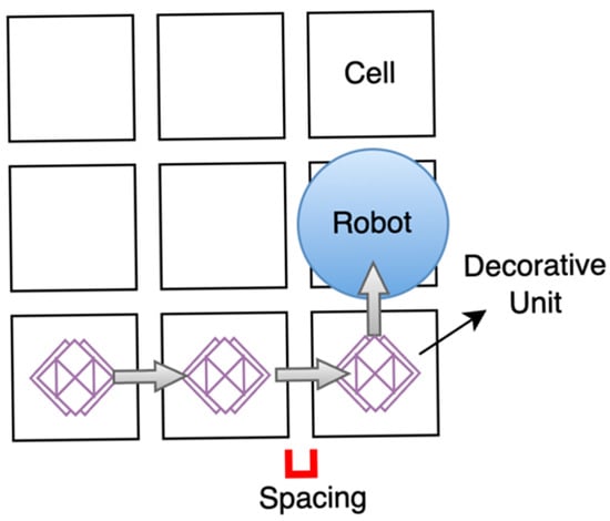 Figure 1. Illustration of the proposed robot’s working principle.
 - CAD-Independent Marking Workflow for Non-Experts: While existing industrial robots rely on pre-loaded CAD files for operation, this system features an intuitive user interface that eliminates technical barriers. This facilitates rapid, on-site creation of intricate designs, such as educational floor games and themed signage, ideal for dynamic environments like schools and offices.
- Targeted Accuracy within a Cost-Effective Framework: The robot is constructed entirely from commercially available, low-cost components. We demonstrate that for the specific application of decorative and functional floor marking, the achieved precision provides a viable, affordable alternative to high-cost industrial-grade systems.
The robot is constructed as a wheeled vehicle equipped with a pen plotter that can apply any desired pattern onto the floor. It is designed to navigate and avoid obstacles autonomously during operation, eliminating the need to clear the workspace of objects. A notable feature of this robot is its independence from CAD files, simplifying its operation for all users.
The robot navigates a grid to create either consistent decorative units or diverse shapes, resulting in a complete floor-marking design. Each cell corresponds to the plotter’s full size, with cell spacing adjustable according to user-specified criteria for the required design.
2. Materials and Methods
The proposed floor-marking system, as depicted in Figure 2, utilizes a decentralized, hierarchical control architecture designed to achieve precise floor-marking without the need for external beacons or pre-localized CAD files. At the primary tier, a Raspberry Pi (RPI) serves as the host computer, managing marking planning and user interface logic via the Kivy library [26]. Low-level actuation and time-critical sensor feedback are managed by a secondary tier of microcontrollers (Arduino UNO) and specialized motion controllers. This architecture ensures stable motion control through the RoboClaw library [27] while the GRBL firmware regulates the three-axis (x, y, and z) plotting system for precise pattern rendering [28].
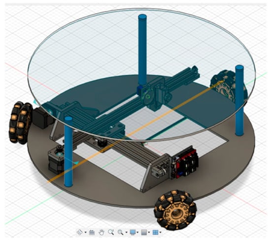
Figure 2.
Schematic of the robot design created using Fusion 360. The design of the omnidirectional wheels is sourced from Autodesk’s gallery.
2.1. Mechanical and Electrical Architecture
2.1.1. Mobile Platform and Plotter
The physical platform is engineered for high-mobility holonomic motion, utilizing a triple-double-omnidirectional wheel configuration, as shown in Figure 3. Each wheel is positioned at an angular offset of 120° from the central axis to facilitate precise multidirectional translation without the need for complex steering maneuvers. Compared to a differential-drive platform, the omnidirectional configuration enables lateral repositioning and in-place orientation adjustments without inducing arc trajectories, which is particularly beneficial for repeatedly aligning the robot within grid cells during precision floor marking. The wheels, with a diameter of 120 mm, were specifically selected to ensure the pen’s reach to the floor. To prevent slippage, the design incorporates double-omnidirectional wheels, and shaft couplers were employed to attach the shafts securely to the wheels.
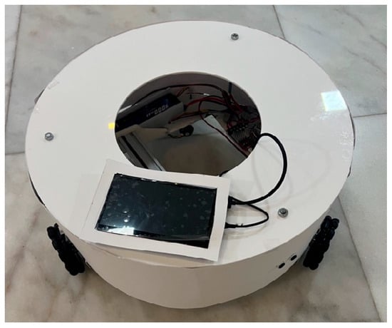
Figure 3.
Photograph of the implemented mobile floor-marking robot prototype used in the experimental evaluation.
The chassis consists of a 6 mm aluminum baseplate, which provides the necessary rigidity to host the plotter and other components. A two-dimensional pen plotter is mounted on the platform, as shown in Figure 4. The plotter provides a maximum drawing workspace of 200 mm × 100 mm, which defines the upper bound of a single grid cell used in the drawing process. Smaller grid cell sizes may be selected as needed to adjust drawing detail or accommodate layout constraints. The marking assembly is a customized three-axis Cartesian system; the x and y axes are belt-driven by NEMA-series stepper motors to ensure repeatable positioning, while the z-axis utilizes a servo-actuated linear lift to manage pen-to-floor contact pressure. The design of the plotter is adopted from [29].
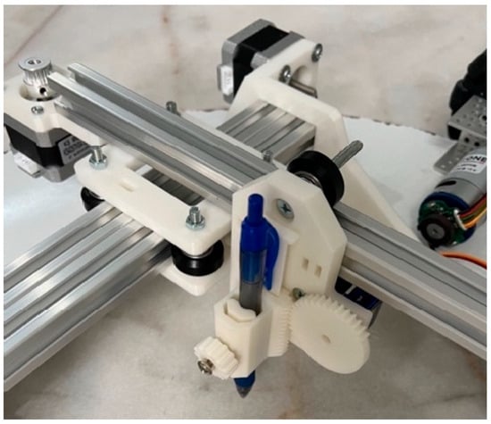
Figure 4.
The pen plotter. The system includes two perpendicular aluminum extrusion axes driven by stepper motors for x- and y- motion. The pen is mounted in a 3D-printed holder, which is vertically actuated by a servo motor.
2.1.2. Actuation and Sensing
Locomotion is achieved using DC motors equipped with incremental encoders, enabling closed-loop control of wheel velocities and distance estimation during navigation. Closed-loop velocity control was implemented for the motors using proportional–integral (PI) controllers embedded in the motor drivers. Controller gains were tuned to minimize velocity error and ensure stable tracking of commanded speeds during short-distance grid movements.
The plotter’s planar motion is driven by stepper motors to provide high repeatability over short travel distances, which is sufficient for grid-based decorative marking tasks. Stepper motors were selected due to their simplicity, cost-effectiveness, and widespread use in computer numerical control (CNC) drawing and plotting systems, where open-loop operation has been shown to provide adequate positioning performance for similar applications [30]. A servo motor is used to control pen lifting and lowering, enabling reliable regulation of pen contact during drawing.
For environment awareness, the robot employs ultrasonic sensors to detect obstacles during navigation. Given the low-speed, short-range motion and controlled operating conditions of decorative floor marking, ultrasonic sensing was considered sufficient for obstacle detection, despite its known limitations in densely cluttered environments. Encoder feedback is used to estimate traveled distances and support grid-based positioning, while ultrasonic measurements enable safe obstacle avoidance during autonomous operation.
2.1.3. Power System
The system is powered by a single 12 V lithium battery selected to support approximately one hour of continuous operation under typical marking conditions. This duration is sufficient to complete multiple grid-based drawing tasks while maintaining stable motor performance and plotting accuracy.
2.1.4. System Layout
A hierarchical electronic architecture was implemented in the design of the floor-marking robot, as illustrated in Figure 5. An RPI serves as the central processing unit, coordinating the motor controllers, plotter, and ultrasonic sensors. It processes feedback and dispatches commands to the various subsystems.
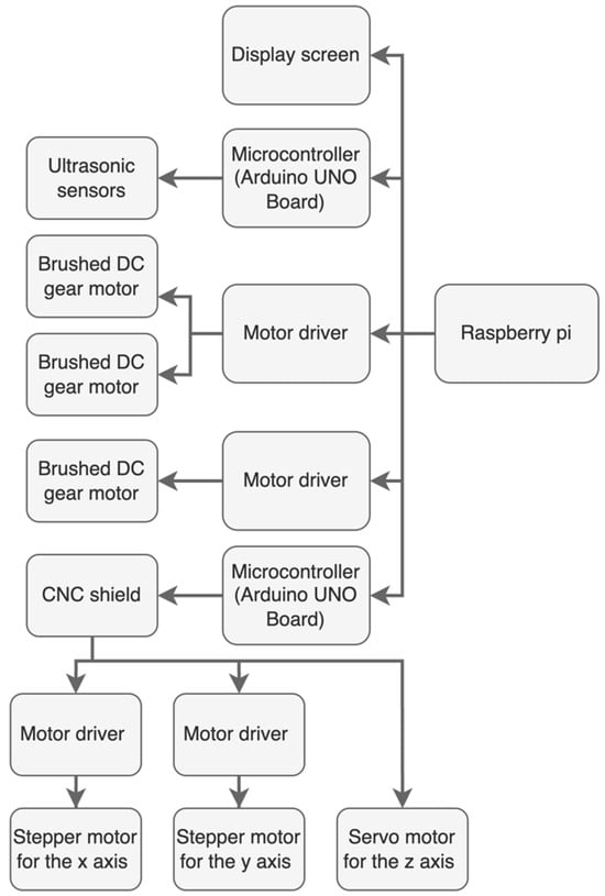
Figure 5.
Layout of the electronic boards.
2.2. Control and Navigation Framework
2.2.1. Omnidirectional Kinematic Model
Robot motion is governed by the kinematic model of a three-wheel omnidirectional platform, as depicted in Figure 6. Let denote the linear velocities of the three wheels, and represent the translational velocities of the robot, and denote the angular velocity. The wheels are positioned at orientations of 0°, 120°, and 240°, each located at a constant radial distance 275 mm from the center of the robot.
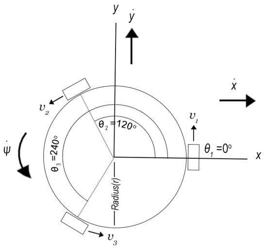
Figure 6.
Layout of the omnidirectional robot. The radius from the center of the robot to each wheel is 275 mm. The wheels are positioned at orientations of 0°, 120°, and 240°.
According to [31], the inverse kinematic relationship between the robot’s translational and angular velocities, expressed in the global frame, and the wheel velocities is given by:
where , , correspond to the fixed wheel orientation angles and denotes the robot heading. The forward kinematic model, expressed in the robot frame, is used in this work to estimate the robot’s translational velocities from encoder-derived wheel speeds, enabling closed-loop navigation control during grid traversal. The kinematic model of the robot with respect to the plotter axis is shown in Figure 7.
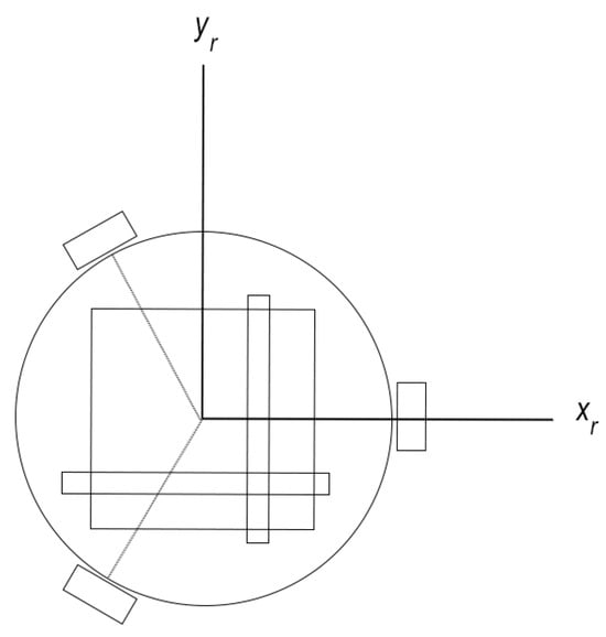
Figure 7.
Orientation of the plotter in relation to the robot, with the forward direction aligned with the positive x-axis.
2.2.2. Grid-Based Drawing Strategy
The core methodology is a grid-based drawing strategy that enables large-scale pattern reproduction without external referencing systems. From the robot’s perspective, the drawing area is discretized into rectangular grid cells, each corresponding to the plotter workspace of 200 mm × 100 mm. The robot begins operation in the first cell, executes the complete drawing associated with that cell, and then navigates to adjacent cells to continue the pattern, as illustrated in Figure 1.
This approach allows complex drawings to be decomposed into manageable units, ensuring consistent drawing quality while simplifying motion planning. Unlike existing floor-marking robots that rely on preloaded CAD files or absolute positioning systems, the proposed method enables flexible pattern generation using image-to-G-code conversion and incremental cell-to-cell navigation. Figure 8 provides an example of this concept, with each block representing one grid cell. Thus, the user should position the robot in a clear environment corresponding to the first cell of the grid, as defined by the drawing’s orientation.
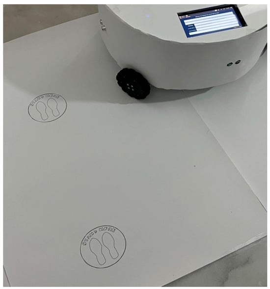
Figure 8.
Application of the robot printing a social distancing logo on the ground. Users can define the number of units and their spacing.
2.2.3. Autonomous Navigation and Obstacle Avoidance
Navigation between grid cells is achieved through encoder-based motion execution, with wheel velocities commanded according to the omnidirectional kinematic model. Distance traveled is estimated from encoder feedback, allowing the robot to move predefined distances corresponding to grid spacing.
Obstacle avoidance is performed using ultrasonic sensors that continuously monitor the robot’s surroundings. If an obstacle is detected within a target grid cell, the robot skips the affected cell, executes a local bypass maneuver, and resumes operation along the original grid path once the obstacle is cleared, as shown in Figure 9. This behavior enables uninterrupted marking without requiring the workspace to be fully cleared prior to operation.
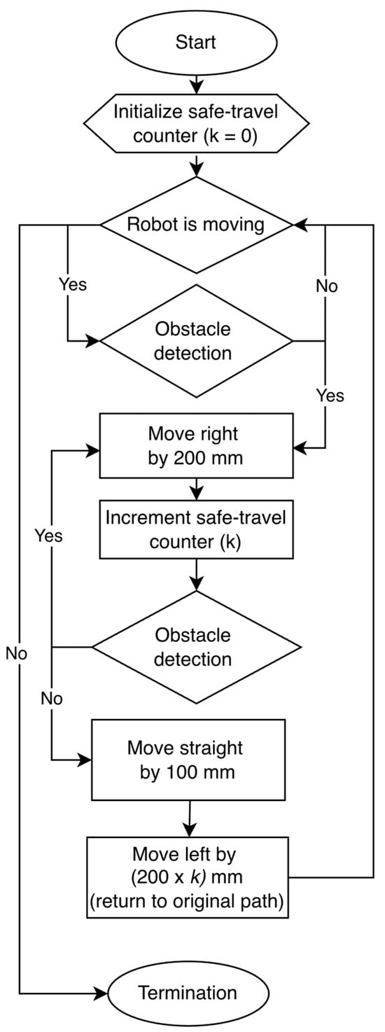
Figure 9.
Flowchart of the obstacle avoidance algorithm.
2.3. Software Pipeline
2.3.1. Pattern Processing and Execution
Design patterns are converted into G-code instructions that define the plotter’s planar and vertical movements using LightBurn (v1.2.00). The generated G-code is transmitted to the plotter controller, where it is interpreted and executed by GRBL firmware to drive the stepper motors and control pen motion [28]. When a pattern exceeds the plotter workspace, it is automatically segmented according to the grid-based drawing strategy. The resulting G-code is transmitted to the plotter controller, which executes the commands sequentially to generate the desired markings.
Key plotter parameters, including steps per millimeter and maximum travel distances, are calibrated to ensure accurate execution and prevent mechanical overrun. These parameters are determined based on the mechanical characteristics of the plotter and are kept constant during operation.
2.3.2. User Interface
A graphical user interface was developed to facilitate intuitive interaction with the robot, as shown in Figure 10. The interface allows users to select drawing patterns, specify grid dimensions, and initiate autonomous operation without requiring prior robotics or programming expertise. This design choice supports the intended use of the system in exhibitions and decorative environments.
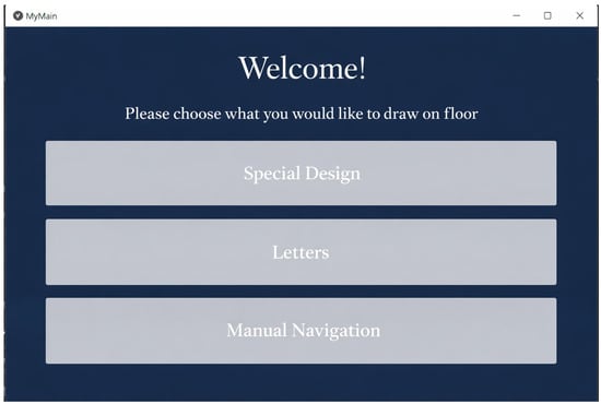
Figure 10.
Welcome screen of the robot’s graphical user interface. The interface is designed to be intuitive for non-expert users, providing simple choices for operation.
3. Results and Discussion
In the following experiments, two performance aspects are evaluated: accuracy and precision. Accuracy refers to the deviation between the commanded travel distance and the physically measured displacement on the floor. Precision refers to the repeatability of motion and drawing outcomes across repeated trials under identical conditions, quantified using overshoot and standard deviation metrics. Due to the absence of an external absolute positioning reference, accuracy is evaluated for straight and lateral motions only, consistent with the grid-based traversal strategy.
3.1. Plotter Performance
The performance of the plotter was evaluated at various stages of the assembly process, focusing on the repeatability and overall quality of the outputs. Proper levelling of the plotter was found to be essential, as misalignment led to incomplete or uneven portions of the drawings.
Repeatability was assessed by producing the same design five times while the robot remained stationary, as illustrated in Figure 11. The results showed only minor variations between iterations, indicating stable and repeatable plotter motion.
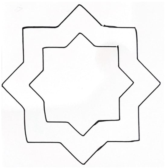
Figure 11.
Evaluation of the plotter’s movement repeatability.
Despite these results, vibrations induced by the pen’s vertical (z-axis) motion were observed, particularly during the drawing of detailed lines. These vibrations occasionally resulted in slight line meandering, as shown in Figure 12. While mechanical refinements reduced these effects, they were not entirely eliminated.

Figure 12.
Outcome of writing a name over several centimeters. Although the design is clear, further enhancements could be achieved through adjustments to the pen holder.
Another example is illustrated in Figure 13, where the robot generated a solid decorative pattern by sequentially filling it line-by-line, using a pen tip approximately one millimeter in width. Despite the extended duration required for this process, it maintained consistent line spacing.
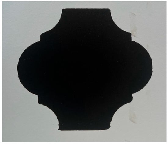
Figure 13.
Detailed view of a solid decorative unit created by the robot.
Overall, the plotter produced satisfactory markings over several centimeters. However, certain limitations were identified. First, fine details within areas smaller than approximately 100 mm2 were not consistently rendered. This limitation is attributed to the effective pen resolution, where very small commanded movements do not translate into observable pen displacement. Second, friction between the pen and the surface introduced resistance that reduced responsiveness during short movements (below approximately 10 mm).
Despite these constraints, the plotter reliably produced circles, lines, letters, and decorative shapes at the intended scale, provided that features were not excessively small. Potential improvements include the use of non-contact marking tools to reduce friction and enable multicolor drawing, as well as more advanced pen modeling approaches similar to those reported in [32,33] for artistic rendering.
3.2. Navigation Performance
Navigation performance was evaluated through a set of experiments designed to assess motion accuracy and repeatability during grid-based traversal. In the first two experiments, the robot was commanded to move a distance of 500 mm, and the actual traveled distance was measured. These tests were repeated from identical starting positions for 15 trials, allowing statistical evaluation of performance under consistent conditions using configurations with either two or three active wheels.
When moving forward with two active wheels and one idle, the average measured traveled distance was 514.1 mm. For lateral movements (either right or left) using all three wheels, the average measured distance was 553.5 mm, as shown in Figure 14. The 95% confidence interval for forward movement ranged from 503.4 to 524.9 mm, indicating more variability compared to lateral movements, which exhibited a tighter confidence interval of 550.7 to 556.4 mm. Both motion directions demonstrated systematic overshoot relative to the commanded distance.
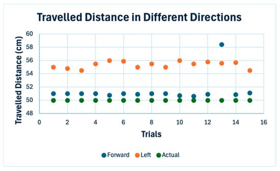
Figure 14.
Measured travel distances for the robot’s lateral and forward movements.
Deviation in the robot’s forward and backward movements was minor, but a significant deviation was observed when moving to the right and left, increasing with distance. After multiple tests, wheel slippage was identified as the source of this deviation. Despite the use of double wheels, slippage could not be entirely prevented. A primary challenge is that slippage is difficult to accurately model within the system. However, the robot achieved straight movements with acceptable small deviations at moderate speeds.
The observed systematic overshoot, particularly in lateral motion, highlights the limitation of encoder-only odometry for holonomic platforms operating without other sensors.
The obstacle avoidance algorithm functioned effectively, detecting objects and preventing collisions.
3.3. Complete Scenario Performance
The overall performance of the robot is depicted in Figure 15, Figure 16, Figure 17 and Figure 18. The robot sequentially wrote each letter and then moved a predefined distance to write the next, with variations in ink density attributed to changes in floor level. The total size of the completed drawing measured approximately 410 mm × 150 mm, as shown in Figure 15.
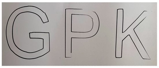
Figure 15.
Three distinct letters scripted by the robot.
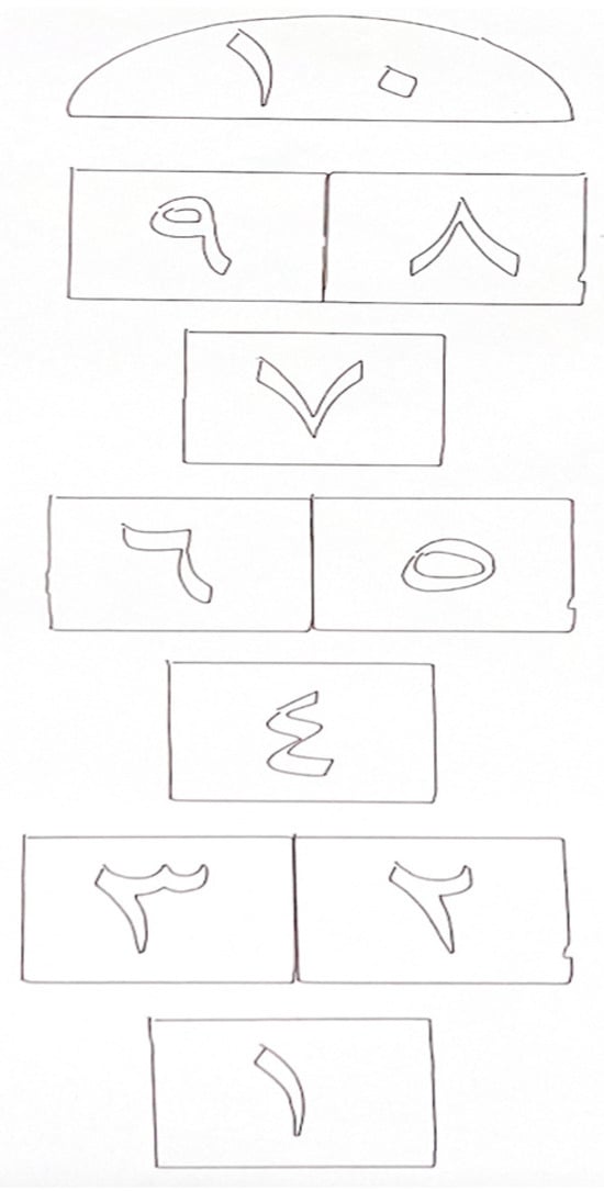
Figure 16.
Floor-based game marked by the robot.
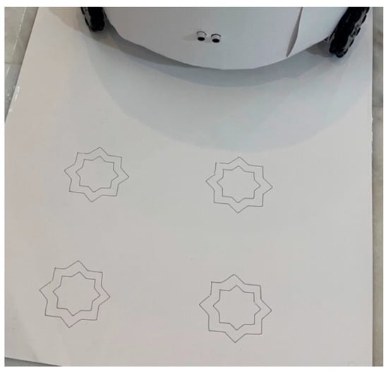
Figure 17.
Decorative drawings on the floor showing user-defined unit arrangements and spacing.
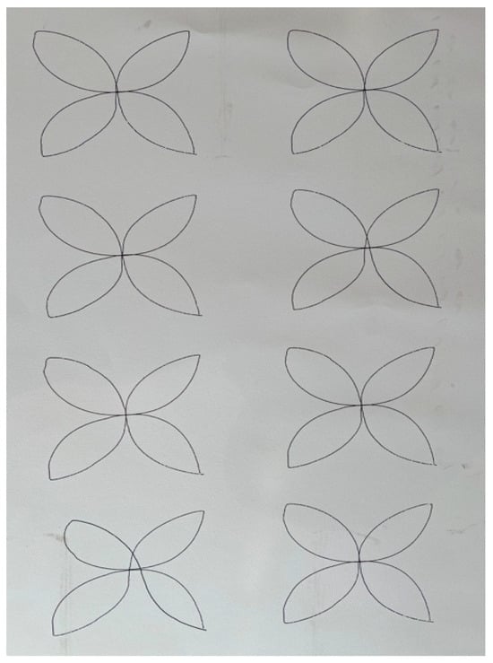
Figure 18.
Examples of decorative drawings on the floor with user-specified arrangements and spacing of the units.
The robot was also employed to print markings for a floor-based game, illustrated in Figure 16. Here, the robot’s movements were confined to forward or backward, maintaining consistent distances with an error margin of approximately +5 mm per step. The final length of the drawing was approximately 1 m.
Furthermore, the robot was tasked with drawing decorative patterns, as shown in Figure 17 and Figure 18, following user specifications for unit quantity and spacing. The pattern in Figure 17 was reproduced six times to assess the uniformity of spacing between units. The chosen spacing for these tests was 100 mm. The resulting average spacing in the forward and backward directions was 127.1 mm with a systematic overshoot of +27.1 mm, and in lateral movements, it was 167.3 mm producing larger overshoot, aligning with previous findings. The standard deviation is 1.6 mm and 3 mm for forward and lateral motion, respectively. These measurements reflect the repeatability and consistency of the robot’s navigation and plotting capabilities across the system. In summary, the performance metrics are illustrated in Table 1.

Table 1.
Summary of performance metrics.
In contrast, commercial solutions such as the HP SitePrint system report a print accuracy tolerance of ±3 mm. This difference highlights the impact of using external referencing systems like total stations to continuously correct positional drift, compared to our encoder-only approach. While our robot demonstrated an average systematic overshoot of several centimeters, particularly in lateral directions, the SitePrint achieves substantially higher absolute positioning accuracy. This comparison underscores that the lower accuracy observed in our system is largely attributable to the absence of such external correction mechanisms, rather than the inherent limitations of the robotic platform itself.
Rather than competing with infrastructure-assisted layout robots in terms of absolute accuracy, the present work targets a different operating regime: infrastructure-independent decorative and informational floor-marking in controlled environments. Within this scope, the achieved repeatability and consistency demonstrate that encoder-only navigation is sufficient for the intended applications, while highlighting clear trade-offs between system complexity and positional accuracy.
According to [34], assessment of construction robots should extend beyond accuracy-based measures and incorporate other metrics such as cost–benefit and safety indicators. Within the context of decorative and informational floor-marking, absolute millimeter-level accuracy is not critical; instead, affordability, repeatability, and safe operation are of greater importance.
From this perspective, the proposed system represents a balanced trade-off between performance and cost. The use of low-cost, commercially available components, such as ultrasonic sensors and encoder-based odometry, significantly reduces system complexity and overall cost while still providing consistent and practically usable marking results.
In terms of safety, the robot mitigates the need for manual floor-marking using paint or tape, which typically requires workers to bend repeatedly and operate close to the ground, posing occupational risks. Additionally, the integration of obstacle detection allows the robot to operate safely in cluttered indoor environments, such as schools or exhibition spaces, where decorative or educational floor markings may be required.
The current evaluation focuses on validating the core navigation and drawing functions under controlled conditions; broader testing across varied floor materials, larger marking areas, and more complex environments will be addressed in future work.
4. Conclusions
A wheeled floor-marking robot was developed, featuring a cylindrical design with an aluminum sheet to house the electronics and an acrylic cover for protection. The robot incorporated a hierarchical electronic structure, with an RPI serving as the host computer. It was equipped with three double-omnidirectional wheels, powered by DC motors enhanced with encoders and controlled through PI schemes. Ultrasonic sensors were employed for obstacle avoidance. The plotter mechanism was operated by stepper motors, aligned along two horizontal channels, and its vertical movement was facilitated by a servomotor. The robot’s development solely utilized commercially available components. Despite these elements, the robot succeeded in producing clear markings while maintaining acceptable error margins. However, testing uncovered several challenges, including difficulties in marking very small areas, overcoming pen–floor friction, and handling marking discontinuities on uneven surfaces. These limitations should be addressed in future studies. Future work will focus on improving localization robustness by integrating additional sensors (e.g., an inertial measurement unit (IMU)) to mitigate slip-induced drift and enable closed-loop correction during long trajectories. Beyond mechanical and localization improvements, future development should also focus on streamlining human–robot interaction, particularly for navigating the workspace, by enabling audio-based commands through the integration of large language models (LLMs) [35]. This approach would reduce the learning curve for non-expert users and support more intuitive robot control. In summary, this work contributes to the field of automation in construction by introducing a versatile and cost-effective solution for floor-marking. The robot’s ability to autonomously create detailed and precise markings enhances efficiency and accuracy in decorative tasks, reducing reliance on manual labor and CAD-based inputs. This work demonstrates a proof-of-concept autonomous floor-marking robot that explores grid-based drawing and CAD-independent control strategies, which may inform future developments in larger-scale or industrial systems.
Author Contributions
Conceptualization, F.A., M.H. and U.B.; methodology, F.A., M.H. and U.B.; software, F.A.; validation, F.A., M.H. and U.B.; formal analysis, F.A., M.H. and U.B.; investigation, F.A., M.H. and U.B.; resources, F.A. and U.B.; writing—original draft preparation, F.A., M.H. and U.B.; writing—review and editing, F.A., M.H. and U.B.; visualization, F.A.; supervision, M.H. and U.B.; project administration, F.A.; funding acquisition, F.A. and U.B. All authors have read and agreed to the published version of the manuscript.
Funding
This research was funded by King Fahd University of petroleum & Minerals (KFUPM), and Saudi Basic Industries Corporation (SABIC).
Data Availability Statement
Data is contained within the article.
Acknowledgments
The authors thank Prince Sultan University for its support in paying the Article Processing Charge (APC). The authors would like to thank KFUPM for using its labs and facilities. During the preparation of this manuscript, the authors used ChatGPT 5.2 for the purposes of improving the writing. The authors have reviewed and edited the output and take full responsibility for the content of this publication.
Conflicts of Interest
The authors declare no conflicts of interest.
Abbreviations
The following abbreviations are used in this manuscript:
| CAD | computer-aided design |
| CNC | computer numerical control |
| GPS | global positioning system |
| IMU | inertial measurement unit |
| LLM | large language model |
| PI | proportional–integral |
| RPI | Raspberry Pi |
References
- National Institute for Occupational Safety and Health (NIOSH); Occupational Safety and Health Administration (OSHA); U.S. Coast Guard (USCG); Environmental Protection Agency (EPA). Occupational Safety and Health Guidance Manual for Hazardous Waste Site Activities. Training 1985, 4, 1. [Google Scholar]
- O’Neill, M.J. Effects of signage and floor plan configuration on wayfinding accuracy. Environ. Behav. 1991, 23, 553–574. [Google Scholar] [CrossRef]
- Jensfelt, P.; Forell, E.; Ljunggren, P. Field and service applications—Automating the marking process for exhibitions and fairs—The Making of Harry Platter. IEEE Robot. Autom. Mag. 2007, 14, 35–42. [Google Scholar] [CrossRef]
- Kitahara, T.; Satou, K.; Onodera, J. Marking Robot in Cooperation with Three-Dimensional Measuring Instruments. In Proceedings of the 35th International Symposium on Automation and Robotics in Construction (ISARC), Taipei, Taiwan, 28 June–1 July 2018; pp. 292–299. Available online: https://www.iaarc.org/publications/2018_proceedings_of_the_35th_isarc/marking_robot_in_cooperation_with_three_dimensional_measuring_instruments.html (accessed on 24 December 2025).
- Tsuruta, T.; Miura, K.; Miyaguchi, M. Mobile robot for marking free access floors at construction sites. Autom. Constr. 2019, 107, 102912. [Google Scholar] [CrossRef]
- Tanaka, K.; Kajitani, M.; Kanamori, C.; Itoh, H.; Abe, Y.; Tanaka, Y. Development of Marking Robot Working at Building Sites. In Proceedings of the 12th International Symposium on Automation and Robotics in Construction (ISARC), Warsaw, Poland, 30 May–1 June 1995; pp. 235–242. [Google Scholar] [CrossRef]
- Robotics, D. BIM-Driven Layout for Construction. Available online: https://www.dustyrobotics.com/ (accessed on 9 April 2025).
- HP SitePrint. Available online: https://www.hp.com/us-en/printers/site-print/layout-robot.html (accessed on 24 December 2025).
- Ali, M.; Mailah, M.; Moiduddin, K.; Ameen, W. Development of an autonomous robotics platform for road marks painting using laser simulator and sensor fusion technique. Robotica 2021, 39, 535–556. [Google Scholar] [CrossRef]
- Wahyuni, S.; Budiarto, H.; Jamilah, N. Mobile robot painted dashed lines as road markings. IOP Conf. Ser. Mater. Sci. Eng. 2021, 1125, 012080. [Google Scholar] [CrossRef]
- Robotic Line Marker for All Sports Pitches. Turf Tank. Available online: https://turftank.com/us/ (accessed on 24 December 2025).
- TinyMobileRobots. TinyMobileRobot Pro-X. Available online: https://tinymobilerobots.com/tinymobilerobot-pro-x/ (accessed on 24 December 2025).
- TinyMobileRobots. TinySurveyor Road-Marking Robot. Available online: https://tinymobilerobots.com/road-marking-robot/tinysurveyor/ (accessed on 24 December 2025).
- Floor Marking Robot. intmach.com. Available online: https://www.intmach.com/floor-marking-robot (accessed on 22 June 2025).
- Lionel. August Robotics. Available online: https://augustrobotics.com/lionel (accessed on 24 December 2025).
- Scalera, L.; Gasparetto, A.; Seriani, S.; Gallina, P. History of drawing robots. In Explorations in the History and Heritage of Machines and Mechanisms; Ceccarelli, M., Aslan Seyhan, I., Eds.; Springer Nature: Cham, Switzerland, 2024; pp. 3–17. [Google Scholar]
- Karimov, A.; Kopets, E.; Leonov, S.; Scalera, L.; Butusov, D. A robot for artistic painting in authentic colors. J. Intell. Robot. Syst. 2023, 107, 34. [Google Scholar] [CrossRef]
- Moura, L. Robot art: An interview with Leonel Moura. Arts 2018, 7, 28. [Google Scholar] [CrossRef]
- Santos, M.; Notomista, G.; Mayya, S.; Egerstedt, M. Interactive multi-robot painting through colored motion trails. Front. Robot. AI 2020, 7, 580415. [Google Scholar] [CrossRef] [PubMed]
- Song, D.; Park, J.; Kim, Y.J. SSK: Robotic Pen-Art System for Large, Nonplanar Canvas. IEEE Trans. Robot. 2023, 39, 3106–3119. [Google Scholar] [CrossRef]
- Liu, Y.; Alias, A.H.; Haron, N.A.; Bakar, N.A.; Wang, H. Robotics in the construction sector: Trends, advances, and challenges. J. Intell. Robot. Syst. 2024, 110, 72. [Google Scholar] [CrossRef]
- Mazzetto, S.; Hosamo, H.H.; Al-Atroush, M.E. How Programmable Construction Can Shape the Future of Sustainable Building in Italy. Sustainability 2025, 17, 1839. [Google Scholar] [CrossRef]
- Rafindadi, A.D.; Kado, B.; Gora, A.M.; Dalha, I.B.; Haruna, S.I.; Ibrahim, Y.E.; Shabbir, O.A. Caught-in/between accidents in the construction industry: A systematic review. Safety 2025, 11, 12. [Google Scholar] [CrossRef]
- Xu, X.; de Soto, B.G. On-site autonomous construction robots: A review of research areas, technologies, and suggestions for advancement. In Proceedings of the 37th International Symposium on Automation and Robotics in Construction (ISARC), Kitakyushu, Japan, 27–28 October 2020; pp. 385–392. [Google Scholar] [CrossRef]
- Zeng, L.; Guo, S.; Wu, J.; Markert, B. Autonomous mobile construction robots in built environment: A comprehensive review. Develop. Built Environ. 2024, 19, 100484. [Google Scholar] [CrossRef]
- Org, K. Kivy: Cross-platform Python Framework for NUI. 2010. Available online: https://kivy.org/#home (accessed on 20 August 2022).
- Roboclaw_Python_Library: The Official RoboClaw Python Library. Basicmicro. Available online: https://github.com/basicmicro/roboclaw_python_library (accessed on 20 August 2022).
- Prezzi, C. Grbl-Servo: Special Grbl Version for Use with Servo Instead of Spindle or Laser. GitHub, 22 February 2018. Available online: https://github.com/cprezzi/grbl-servo (accessed on 4 June 2022).
- Cluts. 2D Pen Plotter—Arduino Writing Machine. 28 December 2021. Available online: https://cults3d.com/en/3d-model/tool/2d-pen-plotter-arduino-writing-machine (accessed on 19 March 2022).
- Das, U.C.; Shaik, N.B.; Suanpang, P.; Nath, R.C.; Mantrala, K.M.; Benjapolakul, W.; Gupta, M.; Somthawinpongsai, C.; Nanthaamorn-phong, A. Development of automatic CNC machine with versatile applications in art, design, and engineering. Array 2024, 24, 100369. [Google Scholar] [CrossRef]
- Klančar, G.; Zdešar, A.; Blažič, S.; Škrjanc, I. Motion modeling for mobile robots. In Wheeled Mobile Robotics: From Fundamentals Towards Autonomous Systems; Butterworth-Heinemann: Oxford, UK, 2017; pp. 13–59. [Google Scholar]
- Karimov, A.; Strelnikov, M.; Mazin, S.; Goryunov, D.; Leonov, S.; Butusov, D. Physically Motivated Model of a Painting Brush for Robotic Painting and Calligraphy. Robotics 2024, 13, 94. [Google Scholar] [CrossRef]
- Zingrebe, D.S.; Gülzow, J.M.; Deussen, O. Robotic Writing of Arbitrary Unicode Characters Using Paintbrushes. Robotics 2023, 12, 72. [Google Scholar] [CrossRef]
- Caputo, C.; Ammar, A.; Johnson, A. Assessment of Traditional and Robotic Approaches to Interior Construction Layout: A Framework and Comparative Study. In ISARC, Proceedings of the International Symposium on Automation and Robotics in Construction, Lille, France, 3–5 June 2024; IAARC Publications: Oulu, Finland, 2024; Volume 41, pp. 113–120. [Google Scholar]
- Koubaa, A.; Ammar, A.; Boulila, W. Next-generation human-robot interaction with ChatGPT and robot operating system. Softw. Pract. Exp. 2025, 55, 355–382. [Google Scholar] [CrossRef]
Disclaimer/Publisher’s Note: The statements, opinions and data contained in all publications are solely those of the individual author(s) and contributor(s) and not of MDPI and/or the editor(s). MDPI and/or the editor(s) disclaim responsibility for any injury to people or property resulting from any ideas, methods, instructions or products referred to in the content. |
© 2025 by the authors. Licensee MDPI, Basel, Switzerland. This article is an open access article distributed under the terms and conditions of the Creative Commons Attribution (CC BY) license.