Abstract
Oscillating fins are devices designed to produce thrust through periodic undulating movements. However, these structures lack flexibility and often provide thrust in only one fixed direction. Observation and biological references suggest that the dorsal fin rays of seahorses can tilt longitudinally in the spine direction, changing the thrust direction. This study aims to analyze the dynamic effects of seahorse dorsal fin inclining and design a flexible bionic thruster based on this principle. Computational fluid dynamics analysis hypothesizes that fin inclination controls the net force direction in the vertical plane. A force sensor and pulley system test platform were constructed to examine the influences of wave features and the inclination angle on thrust in both vertical and horizontal directions, with discrete fin surfaces used to eliminate force interference. Force testing and snapshots indicate that wave velocity positively impacts net force magnitude, while fin inclination allows for control over force orientation. This tiltable oscillating fin thruster possesses more degrees of freedom, leading to better flexibility and providing controllable thrust orientation.
1. Introduction
Research on biomimetic marine propulsors has grown in popularity since 2004 [1]. Biomimetic marine thrusters are more highly efficient, quiet, maneuverable, and even attractable to fish compared with traditional rotary propellers [2,3,4,5,6]. There are two main types of biomimetic fins: median-paired fins and body caudal fins. Median-paired fins are often more feasible to produce and provide more stable movement [7,8]. Within this category, oscillating fins are a prominent example.
Past scholars have proposed eccentric shaft and multi-servo-driven structures to create biomimetic oscillating fins.
The eccentric wheel architecture is distinguished by its heightened integrative capacity, low manufacturing complexity, and user-friendly operability, making it a good choice for real-world applications. In 2021, scholars from China examined the fluid dynamics associated with seahorse dorsal fins and modeled a feasible eccentric shaft structure [9].
Due to their inherent versatility when used in exploring diverse waveform dynamics, multi-servo control mechanisms have attracted substantial scholarly attention. For instance, in 2006, researchers attempted to replicate the locomotive prowess of the Black Ghost Fish ray by designing a contrivance wherein each servo autonomously propelled a fin ray, enabling the meticulous examination of the influence of amplitude, wavelength, and frequency on resultant thrust dynamics [10]. Studies in 2008 postulated sinusoidal patterns of divergence and convergence [11]. Among Chinese NUDT scholars in 2009, there was a particular focus on properties such as oscillation angle and fin material hardness, culminating in meticulously executed experimental analyses [12]. In 2018, scholars designed, stimulated, and tested an oscillating fin thruster and proposed a horizontal moving and hovering mode [13].
To sum up, oscillating fin thruster research focuses on wave features, materials, and dynamic effects through fluid-dynamic simulations and experiments.
The movement patterns of aquatic organisms can be broadly categorized into the categories of linear drive, flexural drive, and torsional drive [14]. The dorsal fin is unique within different fish fin structures, possessing both balancing and propelling functions. A seahorse is a small marine species relying mainly on its dorsal fin for movement. A seahorse’s movement mechanism includes the dorsal fin extending along the back, pectoral fins on both sides of the head, and the tail [15,16]. When the seahorse moves, it maintains a vertical body position, and its forward propulsion comes from the dorsal fin on its back, which generates horizontal thrust through undulating motion. A seahorse’s dorsal fin can provide both vertical and horizontal forces to help it maintain a vertical body position [17,18].
The structure of the seahorse’s dorsal fin is similar to that of ordinary fish, supported by fin rays. The number of fin rays in a seahorse typically ranges from 16 to 20, and the length of fin rays ranges from about 8 to 25 mm.
Our observations revealed that seahorses’ dorsal fins can move up and down in the spine direction (Figure 1).
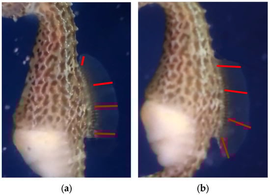
Figure 1.
Seahorse dorsal fins inclining (red lines represent dorsal fin rays) (specimen in Shanghai Ocean Aquarium). (a) Seahorse dorsal fin (inclining upward). (b) Seahorse dorsal fin (inclining downward).
Specifically, each fin ray of the dorsal fin is joined to the spine and controlled by muscle groups. Two pairs of muscles control each fin ray: one pair of muscles (Muscle 2 in Figure 2) is responsible for the left–right oscillation, and a pair of thinner depressor muscles (Muscle 1 in Figure 2) control the pitch of the fin ray [19,20]. In other words, each fin ray has two degrees of freedom for rotation in two directions (Figure 2).
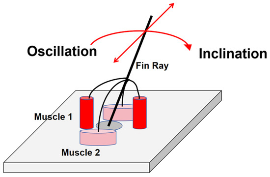
Figure 2.
The muscle structure of the seahorse fin ray (Muscle 2 for oscillation and conventional movement; Muscle 1 for inclination and innovative functions).
Current studies in this field are all based on fin rays’ oscillation, leading to a fixed force orientation or utilizing complicated wave features to provide more flexibility (Figure 3a). Therefore, using conventional oscillating fins, robots should equip at least two fins to achieve more maneuverability and flexibility [21,22].
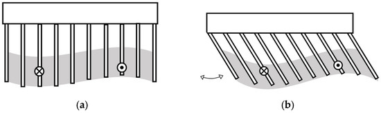
Figure 3.
Conventional oscillating fin and novel tiltable oscillating fin. (a) Conventional oscillating fin side view (each fin ray fluctuates in and out but is perpendicular to the spine). (b) Tiltable oscillating fin side view (each fin ray fluctuates in and out, and all fin rays all fin rays can incline as shown by the arrow).
Based on the seahorse dorsal fin structure, this study aims to determine the fins’ inclination in the spine direction to develop a controllable net force orientation to provide more flexibility from a structural perspective (Figure 3b).
This study aims to design a biomimetics propulsion device based on a detailed imitation of the seahorse dorsal fin structure. Our goal is to provide the fin rays with an additional degree of freedom, allowing them to tilt in the normal direction relative to the fin surface and extend in the direction of the fin surface. This study also intends to investigate the impact of this tilt on the overall thrust of the fin surface. Additionally, this study aims to implement an underwater propulsion system utilizing fins capable of tilting oscillations.
2. Material
2.1. Overall Structure
The mechanical structure of the tiltable oscillating fin thruster consists of three components: the framework, 10 fin rays and drive units, and the fin tilt linkage control system (Figure 4a). The overall length is about 600 mm, and the fin ray length is about 160 mm (Figure 4b).
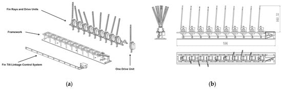
Figure 4.
Overall structure from an exploded view. (a) Exploded view. (b) Dimensions (mm).
2.1.1. Framework
The framework components consist of an upper, perforated carbon fiber plate, which holds the ten drive units, and a larger carbon fiber plate at the bottom that provides support. These two structures are connected by numerous hexagonal standoffs on both sides. At the right end, there is a bracket for mounting the servo that controls the fin tilt system. On top of the upper plate are twenty bearing brackets for supporting the ten fin drive units. The framework actual photo (Figure 5a) and 3D model (Figure 5b) are shown below.
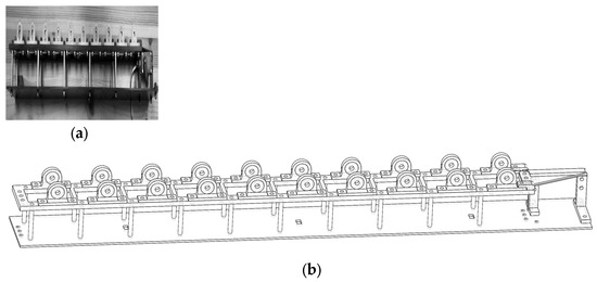
Figure 5.
The framework. (a) Framework (actual photo). (b) Framework (3D model).
2.1.2. Fin Rays and Drive Units
The thruster includes ten identical fin drive units (Figure 6a), with each unit’s fin ray being directly connected to a servo, allowing it to oscillate from side to side (Figure 6b). Additionally, it features a servo bracket, bearings, and bearing brackets.
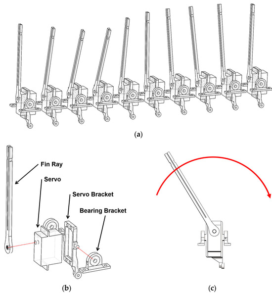
Figure 6.
The fin rays and drive units. (a) Ten fin rays and drive units. (b) Exploded view of one fin unit. (c) Fin oscillation left and right (oscillate by the red arrow, driven by servo).
2.1.3. Fin Tilt Linkage Control System
The fin tilt linkage control system consists of a horizontally positioned servo that drives a set of linkage-slider mechanisms, which move along a connecting rod back and forth, causing all ten fin drive units to tilt in parallel (Figure 7a). The tilt angle can range from vertical, i.e., 90 degrees, to approximately 40 degrees.
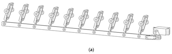
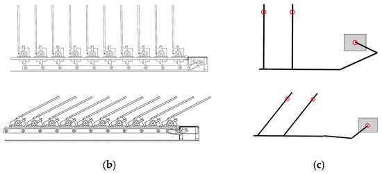
Figure 7.
The inclining mechanism. (a) Fin tilt linkage control system. (b) Inclining mechanism (CAD side view). (c) Inclining system demonstration (red circles mean joints).
2.1.4. Fin Surface
The fin surface is made of 1 mm thick rubber fabric and installed in an arc shape to accommodate the different strokes of the fin’s proximal and distal ends (Figure 8a).
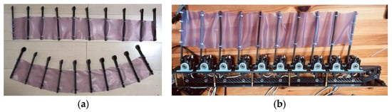
Figure 8.
Fin surface. (a) Fin surface (rubber fabric; the one below is the final arc shape of the fin). (b) Fin surface (installed on robot).
2.2. Control Program
The core of the program driving the fin oscillation is a function that samples points from a sine wave. The input variables for the program are amplitude A, angular velocity ω, and phase difference Φ. A segment containing ten corresponding points moves along the sine wave, with each point representing the angle of a corresponding servo (Figure 9).

Figure 9.
The visualized program logic. (There are 10 servo output points in an interval. The interval moves along a sine wave, and each servo output value varies during interval movement. The variables are sine wave features.).
The angle of the fin tilting system is adjusted directly using a PWM controller.
2.3. Kinematic Equation
2.3.1. Generation and Transformation of Waveforms
2.3.2. Calculation of the Servo Motor’s Motion
The rotation angle of the servo motor on the Y-axis is calculated as follows:
where y represents the servo motor’s position on the Y-axis, and L represents the length of the fin rod.
2.3.3. Servo Motor Speed Control
The rotation velocity of the servo motor on the Y-axis is as follows:
Considering that embedded systems typically use lookup tables for trigonometric functions to improve computational speed, the speed can be rewritten as follows:
3. Methods
3.1. Experimental Objective
The objective of this mechanical testing experiment was to measure the effects of different sine wave parameters and the overall fin tilt on the forces along the x- and y-axes (Figure 10).
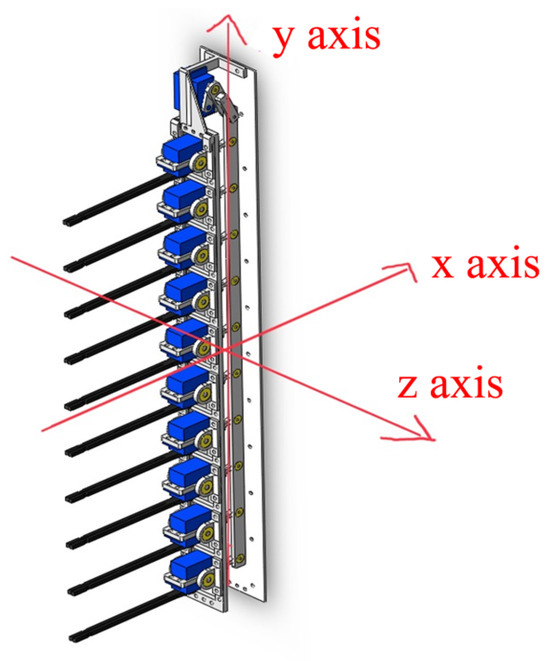
Figure 10.
The coordinate axis diagram (the x-axis is perpendicular to the spine (basement plate), and the y-axis is parallel to the spine).
3.2. Experimental Platform
The experimental platform consisted of a water tank, a propulsion device, a pulley system, and a dynamometer.
3.2.1. Experimental Platform Structure
The propulsion device floated in the water, and the rope was horizontally connected to the device’s center of gravity, passing through a pulley on the right side of the tank and connecting to a high-precision force sensor on top of the tank (Figure 11).
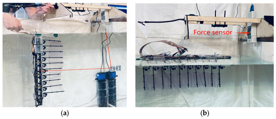
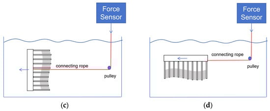
Figure 11.
The experimental platform (the forces moving in two perpendicular directions are measured separately in two modes, and blue arrows means thrust and tension direction). (a) Vertical mode (actual photo). (b) Horizontal mode (actual photo). (c) Vertical mode (diagram). (d) Horizontal mode (diagram).
3.2.2. Device
The force gauge used was HP-20 from Handpi (Figure 12), which is capable of measuring pulling forces up to 20 N with a resolution of 0.01 N and an accuracy of ±0.5%.
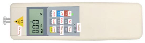
Figure 12.
The HP-20 sensor.
3.3. Experimental Process
The experiment tested how the sine wave feature and fin ray inclination influenced the thrust in both the vertical (y-axis) and horizontal (x-axis) directions.
During this experiment, the variables were each changed individually. For each variable, the thrust was tested in two directions independently.
First, the thruster was set vertically (Figure 13a), balancing the vertical thrust, weight, and buoyancy and only measuring the force perpendicular to the spine (x-axis). After that, it was set horizontally (Figure 13b), balancing the vertical thrust, weight, and buoyancy and only measuring the force parallel to the spine (y-axis).
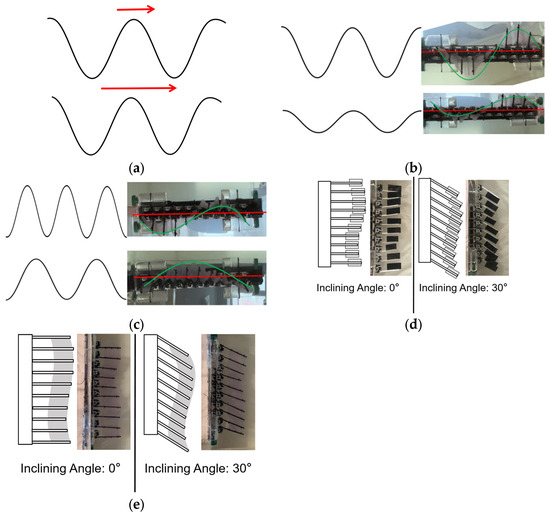
Figure 13.
A demonstration of the variables. (a) Traveling wave velocity. (b) Amplitude. (c) Phase gap. (d) Inclining angle (discrete fin). (e) Inclining angle (continuous fin).
The variables were as follows (Table 1):

Table 1.
Variables for stage one of the variable experiment.
- (a)
- Traveling wave velocity: the speed of the sine wave moving along the fin surface (Figure 13a).
- (b)
- Amplitude: the maximum laterally tilting angle of each fin ray (Figure 13b).
- (c)
- Phase gap: The phase gap of the sine wave. When the phase gap was 18°, the ten fin rays presented half a sine wave cycle, and when the phase gap was 36°, the ten fin rays presented a whole cycle of sine waves (Figure 13c).
- (d)
After independently analyzing the effects of sine wave characteristics and fin ray tilt on the thrust, this study conducted a bivariate experiment by combining the sine wave parameters with fin ray tilt. The following are the combinations of variables (Table 2):
Table 2.
Variables for second stage bivariate experiment.
4. Results
4.1. Traveling Wave Velocity
The traveling wave velocity is the speed of the wave moving on the fin’s surface (Figure 14a).
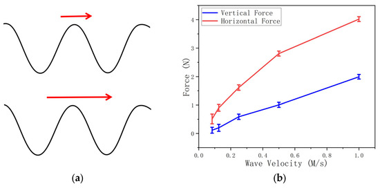
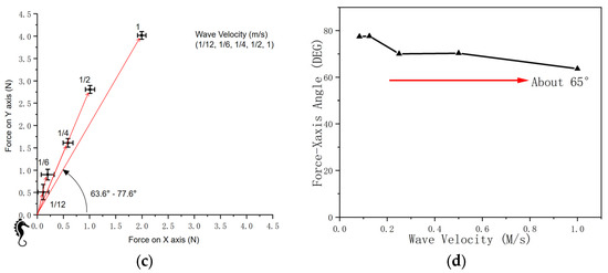
Figure 14.
A comparison of wave velocities. (a) Demonstration of traveling wave velocity. (b) Magnitude of force on vertical and horizontal axes. (c) Force and wave velocity (coordinate system). (d) Force-X-axis angle.
When the wave velocity increases from 1/12 m/s to 1 m/s, the force magnitude in both the vertical and horizontal directions increases (Figure 14b).
The red arrows in Figure 14c demonstrate the net force on the vertical (X-Y) plane. The traveling wave velocity positively influences the net force magnitude while maintaining a relatively stable net force direction.
The angle between the net force direction and the x-axis (Figure 14d) ranges from 63.6 to 77.6 degrees, showing a relatively stable orientation.
Thus, we concluded that the traveling wave velocity positively influences the net force magnitude, but it does not significantly influence the net force direction.
4.2. Amplitude
The amplitude is the maximum laterally fluctuating angle between each fin ray and the perpendicular position (Figure 15a).
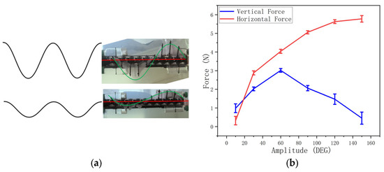
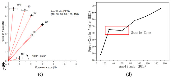
Figure 15.
A comparison of amplitudes. (a) Demonstration of amplitude. (b) Magnitude of force on vertical and horizontal axes. (c) Force and amplitude (coordinate system). (d) Force-X-axis angle.
Amplitudes smaller than 10° or larger than 150° cause unstable force magnitudes.
From 30° to 60°, the amplitude positively influences both vertical and horizontal force magnitudes (Figure 15b). From 60° to 120°, the amplitude positively influences the vertical force while negatively influencing the horizontal force (Figure 15b).
Figure 15c shows the net force magnitudes, orientations, and standard deviations on the vertical and horizontal (X-Y) planes. It demonstrates that from 30° to 60°, the amplitude positively influences the net force.
4.3. Phase Gap
The phase gap is the phase difference between two nearby output points on the control program sine wave. It influences the density of the wave (Figure 16a).
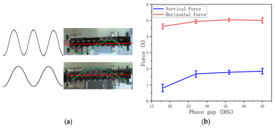
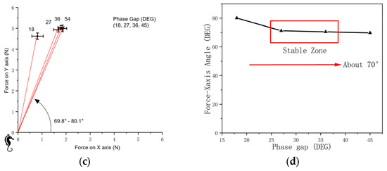
Figure 16.
A comparison of phase gaps. (a) Demonstration of phase gap. (b) Magnitude of force on vertical and horizontal axes. (c) Force and phase gap (coordinate system). (d) Force-X-axis angle.
With a phase gap from 18° to 45°, the force magnitude in both vertical and horizontal directions is almost stable (Figure 16b). The standard deviation shows a minimum value when the phase gap is 36°.
The red arrows in Figure 16c demonstrate the net force magnitudes and orientations on the vertical and horizontal (X-Y) planes. However, a small phase gap (a large wave period) leads to unstable thrust, and the unstable oscillation of the robot can be observed.
For the phase gap from 18° to 45°, the angle between the net force direction and the x-axis (Figure 16d) ranges from 69.8 to 80.1 degrees, showing a relatively stable orientation.
Thus, we can conclude that the phase gap does not have a significant influence on the net force magnitude and orientation.
4.4. Inclining Angle (Discrete Fin)
The inclining angle is the angle between the fin ray and the perpendicular position from the side view (Figure 17a). Notably, fin rays are disconnected blades.
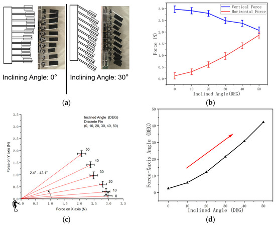
Figure 17.
A comparison of inclining angles (discrete fin). (a) Demonstration of inclining angle (discrete fin surface). (b) Magnitude of force on vertical and horizontal axes. (c) Force and inclining angle (coordinate system). (d) Force-X-axis angle.
On the discrete fin surface, the fin ray inclining angle positively influences the horizontal force magnitude while negatively influencing the vertical force (Figure 17b).
The red arrows in Figure 17c demonstrate the net force magnitudes and orientations on the vertical and horizontal (X-Y) planes.
The angle between the net force direction and x-axis (Figure 17d) increases from 2.4° to 42.1°, being positively influenced by the fin inclining angle.
Thus, we conclude that the fin inclining controls the net force direction.
4.5. Inclining Angle (Continuous Fin)
The inclining angle is the angle between the fin ray and the perpendicular position on the side view (Figure 18a). Notably, fin rays are connected by continuous rubber cloth.
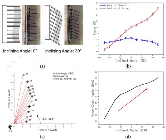
Figure 18.
A comparison of inclining angles (continuous fin). (a) Demonstration of inclining angle (continuous fin surface). (b) Magnitude of force on vertical and horizontal axes. (c) Force and inclining angle (coordinate system). (d) Force-X-axis angle.
On the continuous fin surface, the fin rays’ inclining angle, from −50° to 50°, positively influences the horizontal force magnitude (Figure 18b).
The red arrows in Figure 18c demonstrate the net force magnitudes and orientations on the vertical and horizontal (X-Y) planes. It is concluded that the fin inclination increases the net force angle.
As the inclining angle increases from −50° to 50°, the angle between the net force direction and the x-axis also increases (Figure 18d) from 13.5° to 81°.
4.6. Bivariate Experiment: Wave Velocity and Inclining
In this experiment, both the traveling wave velocity and the inclining angle of the fin rays are changed. The net force magnitude and net force orientation (the angle with the horizontal axis) are measured.
For force magnitude, the result demonstrates that whatever the inclining angle, the wave velocity positively influences the net force magnitude (Figure 19a).
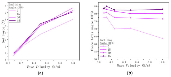
Figure 19.
Bivariate experiment: wave velocity and fin inclination. (a) Influence of wave velocity and fin inclining angle on net force magnitude. (b) Influence of wave velocity and fin inclining angle on net force orientation.
For force orientation, the inclining angle positively influences the angle between the net force and the horizontal axis, and wave velocity does not significantly influence the force direction (Figure 19b).
4.7. Bivariate Experiment: Amplitude and Inclining
In this experiment, both amplitude and fin ray inclining angles are changed. The net force magnitude and net force orientation (angle with horizontal axis) are measured.
For force magnitude, the result demonstrates that whatever the inclining angle, the amplitude positively influences the net force magnitude from 10° to 60° and negatively influences the net force magnitude from 120° to 150°, and the net force magnitude is maintained from 60° to 120° (Figure 20a).
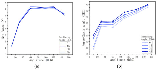
Figure 20.
Bivariate experiment: amplitude and fin inclining. (a) Influence of amplitude and fin inclining angle on net force magnitude. (b) Influence of amplitude and fin inclining angle on net force orientation.
For force orientation, the inclining angle positively influences the angle between the net force and the horizontal axis, and amplitude positively influences the net force orientation from 10° to 60° and from 120° to 150° (Figure 20b).
4.8. Bivariate Experiment: Phase Gap and Inclining
In this experiment, both the phase gap and the inclining angle of the fin rays are changed. The net force magnitude and net force orientation (the angle with the horizontal axis) are measured.
For force magnitude, the result demonstrates that whatever the inclining angle, the phase gap positively influences the net force magnitude (Figure 21a).
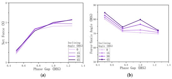
Figure 21.
Bivariate experiment: phase gap and fin inclining. (a) Influence of phase gap and fin inclining angle on net force magnitude. (b) Influence of phase gap and fin inclining angle on net force orientation.
For force orientation, the inclining angle positively influences the angle between the net force and the horizontal axis, and the phase gap does not significantly influence the force orientation. (Figure 21b).
4.9. Snapshots
The snapshots justify the fact that fin inclining influences the net force orientation in real moving situations.
The robot with a continuous fin, after balancing buoyancy and gravity, freely moves in the water. The traveling wave moves downward, and the fin inclining angle is set differently.
As shown in Figure 22a, the fin rays are pointing upward, and the robot is moving horizontally, with a speed of about 0.1 m/s.
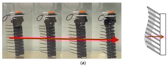
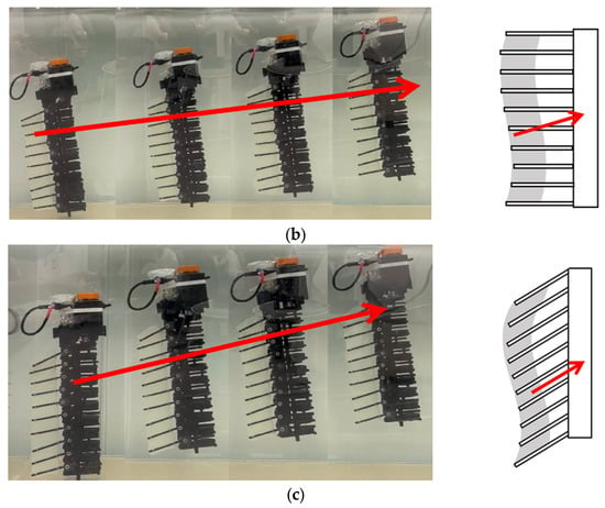
Figure 22.
Snapshots. (Continuous fin). (a) Horizontal movement (fin rays pointing upward). (b) Moving upward (fin rays perpendicular to the spine). (c) Moving upward (fins pointing downward).
As shown in Figure 22b, the fin rays are perpendicular to the spine, and the robot moves forward and upward, with an angle of about 10°.
As shown in Figure 22c, the fin rays are perpendicular to the spine, and the robot moves forward and upward, with an angle of about 20°.
This result demonstrates that fin inclining controls the net force orientation on a continuous fin.
The robot with a discrete fin, after balancing buoyancy and gravity, freely moves in water. The traveling wave moves downward, and the fin inclining angle is set differently.
As shown in Figure 23a, the fin rays are pointing downward, and the robot moves upward, with an angle of about 30°.
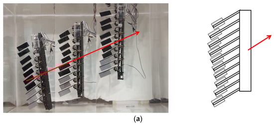
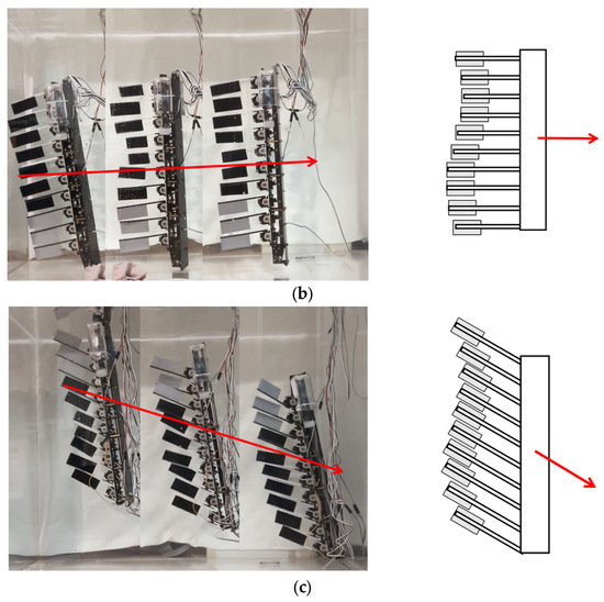
Figure 23.
Snapshots. (Discrete fin). (a) Moving upward (fin rays pointing downward). (b) Horizontal movement (fin rays horizontal). (c) Moving downward (fins pointing upward).
As shown in Figure 23b, the fin rays are perpendicular to the spine, and the robot moves horizontally.
As shown in Figure 23c, the fin rays are pointing upward, and the robot moves downward with an angle of about 30°.
The result demonstrates a strong relationship between the fin rays’ inclining angle and the robot’s moving direction. It is concluded that fin inclination controls the net force orientation on discrete fins.
4.10. Important Values
Based on all experimental data, the following key values are highlighted: maximum force, force orientation, maximum speed in water, and maximum movement angle in water. The discrepancies between the experimental results and the in-water conditions are discussed in detail in the error analysis section (Table 3).
Table 3.
Important values.
5. Discussion
5.1. Analysis of Sine Wave Parameters
Of those three variables, only the traveling wave velocity significantly positively influences the net force, but it does not influence net force directions.
Amplitude has varying influences on these factors. First, a too-small amplitude might lead to an insignificant force magnitude since the fin moving direction varies significantly before it generates a fast enough water flow. At the same time, a too-large amplitude might cause the thruster to turn around the spine axis, causing data to fluctuate.
The phase gap has less influence on the net force because when the wave force is fixed, the sequence of generating forces for each fin ray does not influence the net force. However, different phase gaps show different wave periods for those ten fin rays, leading to different balancing performances.
5.2. Analysis of Fin Inclining
Under both discrete and continuous fin conditions, and regardless of how other variables change, the fin ray inclining angle always positively influences the net force x-axis angle (Figure 24), meaning that the inclination of the fin rays enables researchers to control the net force orientation.
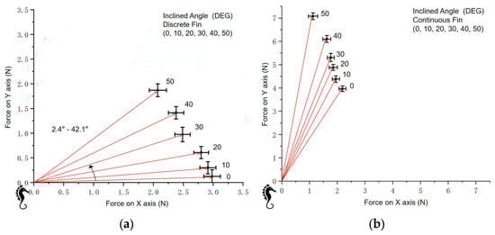
Figure 24.
The force and inclining angle (coordinate system). (a) Force and inclining angle (discrete fin). (b) Force and inclining angle (continuous fin).
Under the same conditions, the continuous fin generates a greater force in the vertical direction (y-axis) compared to the discrete fin. Additionally, the angle between the net force produced by the continuous fin (Figure 24b) and the x-axis is larger than that of the discrete fin (Figure 24a) under equivalent conditions.
This result indicates that the structure of the discrete fin surface eliminates the traveling wave force generated by the moving sine wave, which is present in the continuous fin. This finding led us to develop the model below.
5.3. Model
In the case of the discrete fin surface, the effects of the traveling wave disappear, and the remaining thrust is produced by the oscillation. Therefore, it is hypothesized that the horizontal component of the resultant force (perpendicular to the spine) is generated by the side-to-side oscillation of the fins. With the continuous fin surface, an additional vertical force (parallel to the spine) is clearly observed, indicating that this force is caused by the traveling wave. Based on this observation, a model is proposed.
The net force comprises two components: the oscillating force and the traveling wave force.
The oscillating force is a force component that moves toward the direction in which fin ray’s point, caused by each section of the fin pushing the water from left and right (Figure 24a). Thus, upon changing the fin inclining angle, the oscillating force orientation changes in turn.
The traveling wave force is a force component in the spine direction caused by the traveling wave pushing water in the direction opposite to the wave traveling direction (Figure 25b). Moreover, it relies on a continuous fin surface, which explains why a discrete fin generates a smaller vertical force. As shown in Figure 25d,e, the CFD simulation demonstrates the static pressure in the situation where a sine wave moves 1 m/s in water. The pressure difference on two sides of the sine wave generates a force perpendicular to the fin surface, leading to a net force along the spine direction. This CFD provides a theoretical expatiation of the traveling wave force.
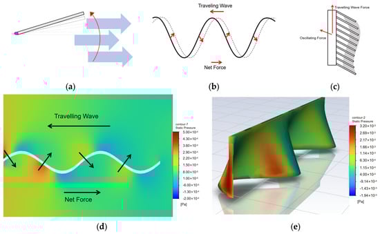
Figure 25.
The net force component model. (a) Oscillating force. (b) Traveling wave force. (c) Net force model. (d) CFD simulation of traveling wave (2D). (e) CFD simulation of traveling wave (3D).
Under real-world conditions (continuous fin), both force components act simultaneously (Figure 25c). Modifying the wave characteristics can influence the magnitude of the net force, while changing the fin tilt angle allows for control over the direction of the net force, driving the thruster forward and either upward or downward.
5.4. Error Analysis
The following results were identified during this analysis:
- The rotation of the thruster led to an unstable thrust orientation, resulting in periodic force fluctuations;
- Disturbances generated at the water surface and the pool’s wall during force measurements could impact accuracy;
- The force test was conducted under static conditions without a flow inlet, which differs from actual dynamic conditions, which might make the result different from actual swimming conditions;
- The rubber fin surface shows unevenness and drape during oscillation, which differs from the ideal situation, especially when the fin is inclined and the surface undergoes uneven tension;
- The free-moving experiment snapshot result does not match the forced experiment result well because of the error in balancing buoyancy and gravity;
- Seahorse dorsal fin locomotion described by the sine wave equation with a parabolically changing amplitude can become more accurate than just using the sine wave [23].
5.5. Feasibility and Innovation
The innovation and application value of this structure lies in the addition of a single servo to control the fin tilt, which introduces an additional degree of freedom to the oscillating fin thruster. Traditional oscillating fins can only generate thrust in a single direction, but with the added tilt functionality, the fin can alter the vertical movement in the forward direction. The theoretical moving direction angle is in the range of ±80 degrees, significantly enhancing the maneuverability and flexibility of conventional oscillating fins (Figure 26).
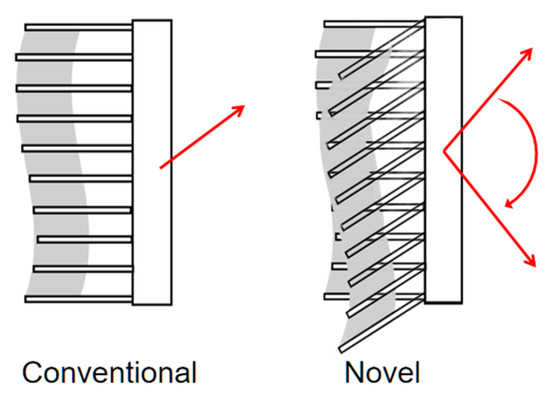
Figure 26.
Feasibility and innovation (Conventional oscillating fin thruster can only generate thrust in a single direction, by the red arrow. With the added tilt functionality, the fin can alter the vertical movement in the forward direction, by the red arrows).
6. Conclusions
The tiltable oscillating fin thruster is a bionic thruster in which each fin ray fluctuates laterally, generating a sine wave to provide thrust. In addition, all fin rays can incline along the spine to control the net force orientation.
Several sine wave features and inclinations are tested in this study. The traveling wave velocity positively influences the force magnitude in both the vertical and horizontal directions while maintaining a fixed net force direction. The amplitude and phase gap influence the stability of the oscillating thruster’s spine axis. The fin’s inclination enables control over the vertical and horizontal forces, leading to the control of force orientation on the vertical plane.
A model is proposed in this study. The net force comprises the vertical force from the traveling wave and the horizontal force from oscillation. Changing the fin inclining angle changes the oscillating force direction and controls the net force direction.
The novel tiltable oscillating fin thruster provides one more degree of freedom than convectional oscillating fins and is more flexible, making it suitable for missions in complex underwater situations.
Author Contributions
Conceptualization, D.L. and Z.L.; methodology, D.L. and Z.L.; software, Z.L.; validation, D.L. and Z.L.; formal analysis, D.L. and Z.L.; investigation, Z.L.; resources, D.L. and Z.L.; data curation, Z.L.; writing—original draft preparation, Z.L.; writing—review and editing, D.L.; visualization, Z.L.; supervision, D.L.; project administration, D.L. and Z.L.; funding acquisition, D.L. and Z.L. All authors have read and agreed to the published version of the manuscript.
Funding
This research was funded by the Key Laboratory of IoT Monitoring and Early Warning, Ministry of Emergency Management.
Data Availability Statement
Restrictions apply to these datasets. The datasets presented in this article are not readily available due to the technical and time limitations. Requests to access the datasets should be directed to the following email: henry666_liu@163.com.
Conflicts of Interest
The authors declare no conflicts of interest.
References
- Aguzzi, J.; Costa, C.; Calisti, M.; Funari, V.; Stefanni, S.; Danovaro, R.; Gomes, H.I.; Vecchi, F.; Dartnell, L.R.; Weiss, P.; et al. Research Trends and Future Perspectives in Marine Biomimicking Robotics. Sensors 2021, 21, 3778. [Google Scholar] [CrossRef] [PubMed]
- Lamas, M.I.; Rodriguez, C.G. Hydrodynamics of Biomimetic Marine Propulsion and Trends in Computational Simulations. J. Mar. Sci. Eng. 2020, 8, 479. [Google Scholar] [CrossRef]
- Wang, R.; Wang, S.; Wang, Y.; Cheng, L.; Tan, M. Development and Motion Control of Biomimetic Underwater Robots: A Survey. IEEE Trans. Syst. Man Cybern. Syst. 2020, 52, 833–844. [Google Scholar] [CrossRef]
- Marras, S.; Porfiri, M. Fish and Robots Swimming Together: Attraction towards the Robot Demands Biomimetic Locomotion. J. R. Soc. Interface 2012, 9, 1856–1868. [Google Scholar] [CrossRef] [PubMed]
- Li, G.; Liu, G.; Leng, D.; Fang, X.; Li, G.; Wang, W. Underwater Undulating Propulsion Biomimetic Robots: A Review. Biomimetics 2023, 8, 318. [Google Scholar] [CrossRef] [PubMed]
- Bu, K.; Gong, X.; Yu, C.; Xie, F. Biomimetic Aquatic Robots Based on Fluid-Driven Actuators: A Review. J. Mar. Sci. Eng. 2022, 10, 735. [Google Scholar] [CrossRef]
- Low, K.H. Current and Future Trends of Biologically Inspired Underwater Vehicles. In Proceedings of the Defense Science Research Conference and Expo (DSR), Singapore, 3–5 August 2011. [Google Scholar] [CrossRef]
- Kato, N. Median and Paired Fin Controllers for Biomimetic Marine Vehicles. Appl. Mech. Rev. 2005, 58, 238–252. [Google Scholar] [CrossRef]
- Quan, X.; Zhao, X.; Zhang, S.; Zhou, J.; Yu, N.; Hou, X. Research on the Undulatory Motion Mechanism of Seahorse Based on Dynamic Mesh. Appl. Bionics Biomech. 2021, 2021, e2807236. [Google Scholar] [CrossRef] [PubMed]
- Epstein, M.B.; Edward Colgate, J.; MacIver, M.A. Generating Thrust with a Biologically-Inspired Robotic Ribbon Fin. In Proceedings of the 2006 IEEE/RSJ International Conference on Intelligent Robots and Systems, Beijing, China, 9–15 October 2006. [Google Scholar] [CrossRef]
- Hu, T.; Shen, L.; Lin, L.; Xu, H. Biological Inspirations, Kinematics Modeling, Mechanism Design and Experiments on an Undulating Robotic Fin Inspired by Gymnarchus niloticus. Mech. Mach. Theory 2009, 44, 633–645. [Google Scholar] [CrossRef]
- Lin, L.; Xie, H.; Shen, L.; Zhou, R. Control System Design and Simulation for Bionic Undulating Fin. In Proceedings of the Chinese Control Conference, Kunming, China, 16–18 July 2008. [Google Scholar] [CrossRef]
- Liu, H.; Curet, O. Swimming Performance of a Bio-Inspired Robotic Vessel with Undulating Fin Propulsion. Bioinspir. Biomim. 2018, 13, 056006. [Google Scholar] [CrossRef] [PubMed]
- Lauder, G.V. Fish Locomotion: Recent Advances and New Directions. Annu. Rev. Mar. Sci. 2024, 7, 521–545. [Google Scholar] [CrossRef] [PubMed]
- Blake, R.W. On Seahorse Locomotion. J. Mar. Biol. Assoc. U. K. 1976, 56, 939–949. [Google Scholar] [CrossRef]
- Kumaravel, K.; Priya, E.R.; Ravichandran, S.; Balasubramanian, T. Morphological Perspectives of the Seahorse Hippocampus kuda (Bleeler) Vertebral System. Int. Sci. Res. J. 2010, 2, 63–69. [Google Scholar]
- Li, X.; Chen, G.; Tang, Y.; Zhong, J. Hydrodynamic Analysis of the Upright Swimming of Seahorse. Phys. Fluids 2024, 36, 021913. [Google Scholar] [CrossRef]
- Botello-Payro, E.; Diez-Robles, L.; Rauh, C.; Delgado, A. Analysis of the Flow Induce by the Undulatory Fin Motion of Seahorse. In Proceedings of the Fachtagung “Lasermethoden in der Strömungsmesstechnik”, Cottbus, Germany, 7–9 September 2010. [Google Scholar]
- Ashley-ross, M.A. Mechanical Properties of the Dorsal Fin Muscle of Seahorse (Hippocampus) and Pipefish (Syngnathus). J. Exp. Zool. 2002, 293, 561–577. [Google Scholar] [CrossRef] [PubMed]
- Consi, T.R.; Seifert, P.A.; Triantafyllou, M.S.; Edelman, E.R. The Dorsal Fin Engine of the Seahorse (Hippocampus sp.). J. Morphol. 2001, 248, 80–97. [Google Scholar] [CrossRef] [PubMed]
- Shang, L.; Wang, S.; Tan, M.; Cheng, L. Swimming Locomotion Modeling for Biomimetic Underwater Vehicle with Two Undulating Long-Fins. Robotica 2011, 30, 913–923. [Google Scholar] [CrossRef]
- Toda, Y.; Suzuki, T.; Uto, S.; Tanaka, N. Fundamental Study of a Fishlike Body with Two Undulating Side-Fins. In Bio-Mechanisms of Swimming and Flying; Springer: Tokyo, Japan, 2004. [Google Scholar] [CrossRef]
- Kulisiewicz, B.E.Z.; Payro, E.B.; Lienhart, H.; Rauh, C.; Delgado, A.; Krupczynski, P.; Schuster, S. Kinematics and Hydrodynamics of Undulatory Fin Motion of Seahorse. In Proceedings of the Fachtagung “Lasermethoden in der Strömungsmesstechnik”, Erlangen, Germany, 8–10 September 2009. [Google Scholar]
Disclaimer/Publisher’s Note: The statements, opinions and data contained in all publications are solely those of the individual author(s) and contributor(s) and not of MDPI and/or the editor(s). MDPI and/or the editor(s) disclaim responsibility for any injury to people or property resulting from any ideas, methods, instructions or products referred to in the content. |
© 2024 by the authors. Licensee MDPI, Basel, Switzerland. This article is an open access article distributed under the terms and conditions of the Creative Commons Attribution (CC BY) license (https://creativecommons.org/licenses/by/4.0/).