Abstract
In this work circularly polarized flat reflectarray antennas are designed to work at downlink frequencies in Ku- and Ka-band. The design approach for circular polarization radiation combines both the variable rotation technique (VRT) and the element size variation technique (ESVT). The reflectarray element employed consists of a rotable split ring operating at 12 GHz (Ku-band) that surrounds two orthogonal sets of parallel dipoles of variable size operating at 20 GHz (Ka-band). Rotations of split rings and different sizes of dipoles are exploited as degrees of freedom by VRT and ESVT for designing focused beams dual band dual circular polarized reflectarrays. The split ring can be used to achieve single focused beams for circular polarization by VRT at 12 GHz, and the set of orthogonal dipoles can be used to achieve two focused beams for dual circular polarization by ESVT at 20 GHz. In this way, the reflectarray element has been used to design two flat dual band circularly polarized reflectarrays that generate three pencil beams either in the same direction or in different directions: one pencil beam with right-hand circular polarization (RHCP) at 12 GHz and two pencil beams with both RHCP and left-hand circular polarization (LHCP) at 20 GHz. The designed reflectarrays are carried out under local periodicity assumption by means of in-house electromagnetic software that applies the Method of Moments in the Spectral Domain. Validations of the in-house electromagnetic software show significant CPU time savings with respect to CPU time consumption provided by commercial software of general purpose as CST electromagnetics software. Numerical results of radiation patterns produced by the designed reflectarrays show efficiencies around 65% and a bandwidth of 6% for a main beam cross-polarization discrimination of 25 dB. The numerical results are satisfactorily validated by CST software and a tolerance errors study has been numerically carried out with acceptable results.
1. Introduction
For satcom-on-the-move (SOTM) applications, there is an increasing interest in developing Ku- and Ka-band antennas that share a single aperture. Conventional solutions use bulky parabolic reflector antennas with very complex feeding systems [1,2,3]. Reflectarrays are an interesting alternative to reflector antennas owing to their low profile, light weight, radiation performance versatility, ease of manufacture, etc. [4]. Single aperture reflectarray antennas have been designed that are capable to provide coverage in Ku- and Ka-band with polarization agility [5,6,7]. In particular, a two-layered reflectarray antenna was presented in [7], which provides dual linear polarization in Ku- and Ka-band for a satellite downlink. Two stacked reflectarrays separated by a double screen frequency selective surface are used in [8] to implement an antenna that provides dual linear polarization at Ku-band for transmit (TX) and receive (RX), and single circular polarization at Ka-band for TX and RX. The impressive performance of this latter antenna is achieved at the expense of a complex multilayered structure with four metallization levels [8].
In this work we focus on the design of a circular polarization reflectarray antenna operating at Ku- and Ka-bands for a satellite downlink. By comparison with the antennas presented in [7,8] that mainly operate in linear polarization, circular polarization is chosen since it is more robust to antenna orientation changes. Two different techniques are combined to achieve the correct phasing in circular polarization in each frequency band. The variable rotation technique (VRT), introduced by Huang and Pogorzelski [9], is employed at Ku-band to achieve singular circular polarization. This technique has been used in the past for the design of single band [10], and dual band circular polarization reflectarray antennas at Ka-band [11,12]. In [13] a circularly polarized tri-band and three pencil beam reflectarray is shown. This reflectarray operates at 1.6, 20.0 and 29.8 GHz with right-hand circular polarization (RHCP), left-hand circular polarization (LHCP) and RHCP respectively. However, although the results are satisfactory, the proposed antenna is bulky and difficult to manufacture. The element size variation technique (ESVT) [14,15], is the phasing technique employed at Ka-band, and this technique makes it possible to operate the antenna in dual circular polarization. A dual circular polarization reflectarray based on the ESVT was designed in Section III.B of [16], and the VRT was subsequently used to separate the beams of the orthogonal circular polarizations (see section III.C of [16]). However, the designed antenna only works at single frequency band. The reflectarray element employed in our work consists of a split ring surrounding two orthogonal sets of dipoles on a two-layered substrate. The split ring is used to achieve single focused beam for circular polarization by VRT at 12 GHz as in [11], and the set of orthogonal dipoles is used to achieve two focused beams for dual circular polarization by ESVT at 20 GHz as in section III.B of [16]. The reflectarray element used in this paper was already introduced in [17] as a potential element to achieve dual band dual circular polarization at Ka-band for TX and RX. However, reflectarray antenna designs were not provided in [17]. In [18] this element was used to show the feasibility of a reflectarray design for the separation of two unfocused beams in dual-band for orthogonal circular polarizations by means of VRT using a single feeder. Although successful experimental results were shown in [18] to validate the proof of the concept, VRT was only used for the separation of two unfocused beams. Therefore, variation size and rotations capabilities of the reflectarray element were not exploited as degrees of freedom to focus the reflected beams by means of ESVT and VRT. The mean novelty of this work shows that both the rotations of split rings and the different sizes of dipoles are exploited as degrees of freedom by VRT and ESVT for designing focused beams dual band dual circular polarized reflectarrays for Ku- and Ka-band satellite downlink applications. We provide two different antenna designs that show the feasibility of the element in Ku- and Ka-band satellite downlink applications for circular polarization. Each designed antenna provides single circular polarization radiation at 12 GHz by variable rotation capability of the element, and dual circular polarization radiation at 20 GHz by variable size capability of the element, either in the same beam direction at both frequencies or in different beam directions. Since successful experimental validations was shown in [17,18] using the same reflectarray element for different applications, numerical results will be only shown in this work. Promising results for Ku- and Ka-band satellite downlink applications for circular polarization are obtained. Such promising results suggest that proposed architecture could be applied for 5G and beyond applications [19].
2. Reflectarray Element
The reflectarray element used in this work is based on a two-layered substrate which hosts two levels of metallization, as shown in Figure 1a,b.
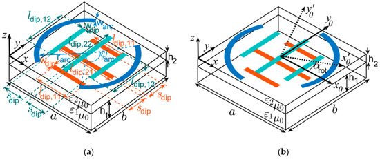
Figure 1.
(a) Reflectarray element based on two orthogonal sets of parallel dipoles surrounded by a non-rotated split ring. (b) Reflectarray element with rotated split ring and definition of rotation angle αrot.
The element consists of a split ring that surrounds two orthogonal sets of parallel dipoles. The split ring is printed on the upper side of the upper dielectric layer, and the sets of dipoles are printed on both opposite sides of this dielectric layer. The split ring is aimed at the design of the antenna at 12 GHz, and the parallel dipoles are used for the design at 20 GHz. A bottom dielectric layer is introduced as a separator between the upper layer and the ground plane. The material used for the upper layer and the separator is a commercial material with low RF losses, Rogers Duroid 5880, which means that the multilayered substrate supporting the reflectarray element is composed of two dielectric layers with thickness hi and complex permittivity εi = ε0εri(1 − jtanδi) −i = 1,2- (see Figure 1), where εr1 = εr2 = 2.2, tanδ1 = tanδ2 = 0.0009, h1 = 1.524 mm, h2 = 0.787 mm and ε0 the vacuum permittivity. The relative permittivity and loss tangent values are provided by [20] at 10 GHz. A period a = b = 8 mm (which is roughly 0.533λ at 20 GHz) has been selected for the unit cell of the reflectarray to provide both enough room for the dipoles and the split ring and, at the same time, to avoid the appearance of grating lobes. The center of central dipoles on each side of the upper dielectric layer are located at the center of each side of the dielectric layer of cell and the lateral dipoles are symmetrically separated from the central dipole (see Figure 1a). In similar way, the center of the circular arcs are located at the center of the cell and these arcs are symmetrical with respect to the mirror symmetry axis y’0 (see Figure 1b). The geometrical parameters of layout have been adjusted to provide a smooth and linear behavior of the phase-shift for variations of both the arc lengths of the split ring at 12 GHz, and the dipoles lengths at 20 GHz. The fixed final dimensions chosen are relation of lengths between the dipoles ldip,11 = 0.6 ldip,21, ldip,12 = 0.73 ldip,22, the widths of dipoles and arcs wdip = warc = 0.2 mm, separation between dipoles sdip = 1.8 mm, and radius of arcs rarc = 3.575 mm. The lengths ldip,21 and ldip,22 of central dipoles printed on each side of the upper dielectric layer will be the geometrical design parameters for reflectarray design process at 20 GHz. The rotation angle αrot of the mirror symmetry axis of the split-ring (see Figure 1b) and the subtended angle ψarc by extremes of the arcs of the split rings (see Figure 1a) will be the geometrical design parameters for reflectarray design process at 12 GHz.
An in-house electromagnetic software that applies the Method of Moments in the Spectral Domain (MoM-SD) is used for the analysis of the reflectarray cell with rotated split ring and two orthogonal sets of parallel dipoles of Figure 1b in a periodic environment [21,22] (i.e., periodic boundary conditions are considered) illuminated with linearly or circular polarized plane wave (i.e., TEz, TMz polarization or combination). The incidence direction of the plane wave is given by the spherical angular coordinates θi and ϕi. According with [21,22], in the method of moment in spectral domain approach [23], the multilayer medium is modelled by means of bidimensional spectral multilayer dyadic Green functions [24] which takes into account permittivity, losses tangent and thickness of each dielectric layer of the multilayer medium and the ground plane as perfect electric conductors of negligible thickness. The layout is also modelled as perfect electric conductors of negligible thickness. Entire domain basis functions accounting for edge singularities are used in the approximation of the surface current density on split ring and dipoles as shown in [21,22] respectively. According with the results shown in [21,22], a house code based on MoM-SD with proposed edge singularities entire domain basis functions which lead CPU time consumptions of electromagnetics analysis of the element which are roughly 30-times faster than those obtained using CST frequency domain solver. Since a reflectarray has thousands of elements, the analysis tool of reflectarray element should be called tens of thousands of times in a reflectarray design. In this way, the house-code is more suitable than CST software for reflectarray designs.
The MoM-SD makes it possible to characterize the reflectarray cell of Figure 1b by means of a reflection matrix R0 relating the complex x0 and y0 components (the x0 and y0 axes of Figure 1b are parallel to the dipoles) of the reflected electric field and the incident electric field for a plane wave impinging on the cell in a direction given by the angular spherical coordinates θi and ϕi. The components of R0 are defined in Equation [16]:
The components of the matrix R0 are complex numbers. The phase of the complex numbers of diagonal components of matrix R0 are key in reflectarray designs. In the same way, a matrix R0’ can be defined relating the complex x’0 and y’0 components of the reflected and incident field, where the axes x’0 and y’0 of Figure 1b are obtained by rotating the axes x0 and y0 an angle αrot around the z axis (αrot is the rotation angle of the split ring between Figure 1a,b). R0’ can be obtained in terms of R0 as shown below [16]:
Since the components of matrix R0 are complex numbers, the components of matrix R0’ are also complex numbers. A third matrix Rc can be defined which relates the LHCP and RHCP complex components of the reflected and incident field for the impinging wave as shown below [16]:
It turns out that Rc can be also easily obtained in terms of R0 by means of the transformations shown in [25]. Since the components of matrix R0 are complex numbers, the components of matrix Rc are also complex number.
Huang and Pogorzelski demonstrated that the phases of the coefficients RRHCP,RHCP and RLHCP,LHCP defined in (3) have a linear dependence on the rotation angle αrot defined in Figure 1b provided R’0,xx = −R’0,yy (i.e., the gap between the phases of the complex numbers R’0,xx and R’0,yy is 180°). This linear dependence can be written as:
Moreover, under this condition, the cross-polar coefficients RRHCP,LHCP and RLHCP,RHCP are negligible. Equation (4) shows the dependence with respect to the rotation angle αrot of phase-shift produced by the reflectarray cell in the phase of the circularly polarized electric field of the reflected wave. According with Equation (4) this dependence is linear with respect to the rotation angle αrot. Moreover, if the rotation angle αrot is varied from −90° to +90°, the phase-shift range is a cycle of 360 deg. So, any required phase shifts for the elements of a circularly polarized reflectarray antenna can be adjusted by simply rotating the elements of the antenna an adequate amount [9]. This is called the VRT. In this way, the subtended angle of ψarc will be adjust to preserve the condition R’0,xx = −R’0,yy while that the rotation angle αrot will be adjust to match the phase shifts to the required phase shift for right-hand circular polarization in each reflectarray element at 12 GHz. On the other hand, the condition R0,xx = −R0,yy is preserved at 20 GHz by adjustment of the lengths ldip,21 and ldip,22 of central dipoles of each orthogonal set without rotations. Under this condition, Equation (4) is satisfied but with αrot = 0 since the dipoles are not rotated (i.e., equation is satisfied for the dipoles at 20 GHz). So, as the length of dipole with direction parallel to x0 axis, ldip,21 is varied, the value of is changed. According with [26,27], 360 deg of phase shift range of can be achieved by variation of lengths of three parallel dipoles using an appropriated relation between lengths of lateral dipoles and the length of central dipole (in our case we have fixed the relations ldip,11 = 0.6 ldip,21, ldip,12 = 0.73 ldip,22). In this way, the lengths of dipoles lengths ldip,21 and ldip,22 will be adjusted for both, to preserve the condition R0,xx = −R0,yy and to match the phase shifts to the required phase shift in each reflectarray element at 20 GHz.
Figure 2b shows how ψarc must be modified as αrot is varied to keep R’0,xx = −R’0,yy. And Figure 2c shows how the phases of RRHCP,RHCP and RLHCP,LHCP linearly vary with αrot in accordance with Equation (4) when the conditions of Figure 2b are fulfilled. Our MoM-SD results of Figure 2c have been compared with the results provided by the commercial software CST [28], and good agreement has been found between both sets of results. We would like to point out that the average CPU time consumption produced by in-house code is 0.77 s for each analysis of the phase curves shown in Figure 2c while that, the average CPU time consumption produced by CST frequency domain solver under unit cell boundary conditions and Floquet port is roughly 540 s for each analysis using adaptive mesh option. These CPU time consumptions are obtained in a laptop computer with processor Intel Core i7-6700HQ at 2.6 GHz with 32 GB of RAM memory.

Figure 2.
(a) 3D CST model picture. (b) Numerical adjusted values of ψarc which preserve the condition R’0,xx = −R’0,yy as a function of the rotation angle αrot. (c) Simulated phase of the reflection coefficients RRHCP,RHCP and RLHCP,LHCP provided by the pairs (ψarc, αrot) shown in (a) as a function of the rotation angle αrot. The numerical results are shown at 12 GHz under incidence angles θi = 19°, ϕi = 0° and fixed lengths of dipoles ldip,21 = ldip,22 = 5 mm.
The results of Figure 2b,c have been obtained for fixed lengths of the longest dipoles in Figure 1a,b, ldip,21 = ldip,22 = 5 mm. However, these lengths have to be varied in order to make the element work for a circularly polarized reflectarray at 20 GHz, which will unavoidably affect the element performance at 12 GHz. Figure 3a shows to which extent the condition R’0,xx = −R’0,yy is lost when ldip,21 = ldip,22 departs from 5 mm, and Figure 3b shows how this departure affects the magnitude of the non-diagonal cross-polar coefficients of the matrix Rc in (3). Please note that the larger the departure of the phase difference from −180° in Figure 3a, the larger the cross-polarization in Figure 3b, which reaches a maximum of −14 dB when ldip,21 = ldip,22 = 6 mm and αrot = 0°.
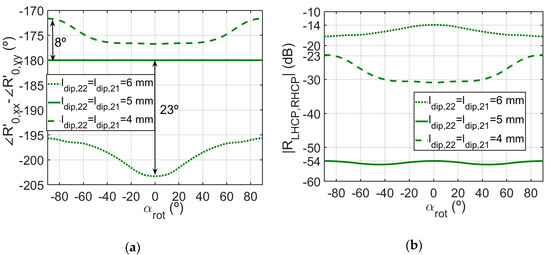
Figure 3.
(a) Simulated difference between the phases of R’0,xx and R’0,yy provided by the pairs (ψarc, αrot) shown in Figure 2a for different values of ldip,21 = ldip,22. (b) Simulated magnitude of the cross-polar coefficient RLHCP,RHCP (provided by the pairs (ψarc, αrot) shown in Figure 2a) as a function of the rotation angle αrot. The numerical results are shown at 12 GHz under incidence angles θi = 19°, ϕi = 0°.
If we use the element of Figure 1a,b for the design of a circularly polarized antenna by ESVT at 20 GHz, the lengths of the dipoles ldip,21 and ldip,22 have to be adjusted to preserve the condition R0,xx = −R0,yy, which is necessary to keep the sense of circular polarization after reflection on the reflectarray antenna. Figure 4a shows a color-map of the subtraction as a function of the dipole lengths ldip,21 and ldip,22. These results have been obtained for fixed values of ψarc as αrot (we have chosen ψarc = 118.9° and αrot = 0° in accordance with Figure 2a). Black solid lines in Figure 4a indicate the locus of pairs of dipole lengths that lead to the condition R0,xx = −R0,yy. Figure 4b shows the phases of R0,xx and R0,yy obtained while using the pairs of dipole lengths defined by the black solid lines of Figure 4a. These phase curves show a smooth behavior within a phase range of 388° (larger than a cycle of 360°) where condition R0,xx = −R0,yy is satisfied. The phase curves of RRHCP,RHCP and RLHCP,LHCP for circular polarization applications are also shown, which coincide with those of R0,xx since αrot = 0° (see Equation (4) and Figure 1b). Since the phase curves for RRHCP,RHCP and RLHCP,LHCP coincide, this can be used to design a circular polarization reflectarray by means of ESVT that works for both RHCP and LHCP conditions as will be shown in the next Section. The phases curves obtained in Figure 4b with our MoM-SD software have been compared with CST, and good agreement has been found. The average CPU time consumptions for analysis are similar to those obtained in the analysis shown in Figure 2. The CPU time consumptions are obtained in a laptop computer with processor Intel Core i7-6700HQ at 2.6 GHz with 32 GB of RAM memory.
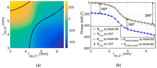
Figure 4.
(a) Color-map showing the simulated difference between the phases of R0,xx and R0,yy as a function of the dipole lengths ldip,21 and ldip,22. Black solid lines indicate the pairs of dipole lengths leading to the condition R0,xx = −R0,yy. (b) Simulated phases of R0,xx and R0,yy provided by the pairs of dipole lengths defined by the black solid lines of (a). The phases of RRHCP,RHCP and RLHCP,LHCP are also shown. These results are obtained at 20 GHz under incidence angles θi = 19°, ϕi = 0° when ψarc = 119° and αrot = 0°.
As in the case shown in Figure 3, the conditions for circular polarization design at 20 GHz shown in Figure 4 may change when ψarc and αrot are modified to adjust the phase shift of the element for circular polarization applications by VRT at 12 GHz. Figure 5a shows the difference between the phases of the R0,xx and R0,yy when the values of ψarc and αrot used in Figure 4 are varied. Additionally, Figure 5b shows how this affects the cross-polar coefficient RLHCP,RHCP. Please note that the increase in the magnitude of RLHCP,RHCP is much larger in Figure 5b than in Figure 3b. In fact, |RLHCP,RHCP| reaches −5 dB in Figure 5b when ψarc = 109.8°, αrot = 45° and ldip,21 = 5.9 mm, which is due to the fact that the difference between the phases of R0,xx and R0,yy departs 78° from −180° in Figure 5a (a maximum departure of 23° is observed in Figure 3a). This means that the cross-polarization performance of a dual-band circular polarization reflectarray antenna based on the element of Figure 1 will be better if we first adjust the dimensions of the split ring by VRT at 12 GHz and then fix the dipoles lengths by ESVT at 20 GHz, instead of first fixing the dipoles lengths at 20 GHz, and then adjusting the split rings at 12 GHz.
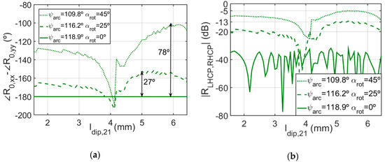
Figure 5.
(a) Simulated difference between the phases of R0,xx and R0,yy for different values of ψarc and αrot (b) Simulated magnitude of the cross-polar coefficients RLHCP,RHCP for different values of ψarc and αrot. The results are obtained for the pairs of lengths of dipoles ldip,21 and ldip,22 indicated by the black solid lines of Figure 4a at 20 GHz under incidence angles θi = 19°, ϕi = 0°.
3. Reflectarray Design and Results
A circular flat reflectarray which consists of 489 elements arranged in a 25 × 25 square grid with cell size of 8 × 8 mm has been designed (the diameter of the antenna is 20 cm). The elements are of the type shown in Figure 1b. The reflectarray is intended to radiate a RHCP focused beam in the direction ϕbeam = 0° and θbeam = 19° (see Figure 6) at 12 GHz, and two RHCP and LHCP focused beams in the same direction at 20 GHz. It is illuminated by a feed horn whose radiated pattern is modeled as cosq(θ) model for circular polarization [29]. In particular, the models are cos10(θ) at 12GHz and cos13(θ) at 20 GHz (see [7] for details). The feed illuminates the edges of the reflectarray with a taper of −12 dB at both frequencies, 12 and 20 GHz. Its face center is located at the coordinates (xf, yf, zf) = (−0.0639, 0.0, 0.185) (m) with respect to the coordinate system with origin at the center of the reflectarray that is shown in Figure 6.
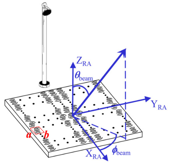
Figure 6.
Reflectarray antenna picture. Coordinate system with origin at the reflectarray center and beam direction.
The reflectarray design is carried out in two stages. In the first stage we make use of Equation (4) to obtain the desired phase shift in each element according to Equation (3.3) of [4] at 12 GHz. The rotation angle αrot and the arc angle ψarc are adjusted so that R’0,xx = −R’0,yy and (4) are fulfilled while ldip,21 = ldip,22 = 5 mm. Once the split ring parameters αrot and ψarc have been fixed for each reflectarray element, in the second stage the required phase shifts are determined at 20 GHz by means of Equation (3.3) of [4]. For each pair values of αrot and ψarc, curves similar to those of Figure 4 are generated in each element, and the dipoles lengths ldip,21 and ldip,22 are adjusted so that condition R0,xx = −R0,yy is fulfilled. As commented in Section 2, the procedure based on first adjusting the split rings at 12 GHz, and subsequently adjusting the dipole lengths at 20 GHz, leads to lower cross-polarization values. Figure 7a,b show the layouts printed on bottom and upper sides of the upper dielectric layer respectively.
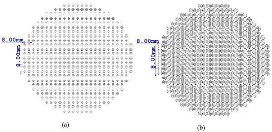
Figure 7.
(a) Reflectarray layout printed on the bottom side of the upper dielectric layer. (b) Reflectarray layout printed on the upper side of the upper dielectric layer.
The designed reflectarray has been analyzed with both our MoM-SD code and CST under the local periodicity assumption (LPA) [4]. The radiation patterns have been computed in terms of the electric and magnetic currents on the reflectarray surface as shown in [30]. The numerical results obtained for cuts of the radiation patterns with elevation plane (y = 0 plane in coordinate system defined in Figure 6) and azimuth plane (constant plane which includes the direction of maximum of radiation and the YRA-axis defined in Figure 6) are shown in Figure 8a,b. Good agreement is found between our MoM-SD results and those provided by CST for the copolar components of the radiated field.
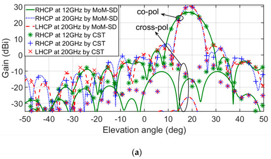
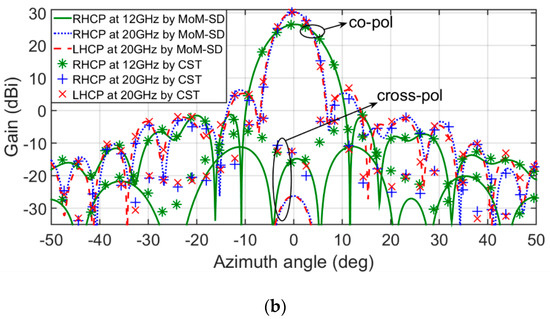
Figure 8.
Main cuts of the simulated radiation patterns at 12 GHz for right-hand circular polarization (RHCP) and 20 GHz for both RHCP and left-hand circular polarization (LHCP). MoM-SD and CST results are shown. (a) Elevation cuts. (b) Azimuth cuts.
The overall performance of the antenna is summarized in Table 1, where cross-polar discrimination (XPD) is defined as the difference in dB between the copolar level and the cross-polar level at the pointing direction of the main beam. Note the cross-polar levels at 20 GHz are much smaller than those at 12 GHz. This is logical since the design at 12 GHz (first stage) did not use the exact final values of the dipole’s lengths, but the design at 20 GHz (second stage) used the exact final values of both the arc lengths/rotations and the dipole lengths. Figure 9a,b show the maximum gain for co-polar and cross-polar radiated components versus frequency in each frequency band. We can check that the gain remains stable (variations less than 1 dB) within the frequency bands where XPD >25 dB. In fact, the main bandwidth limitation of the antenna stems from the cross-polarization, not from the gain.

Table 1.
Overall numerical performance of the designed circular polarization reflectarray that generates RHCP at 12 GHz, and RHCP and LHCP at 20 GHz.
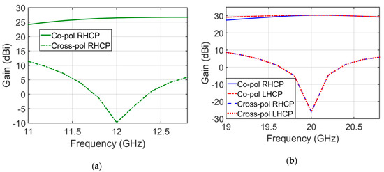
Figure 9.
(a) Maximum of simulated gain versus frequency for frequencies closer 12 GHz. (b) Maximum gains versus frequency for frequencies closer 20 GHz.
The procedure used to design a reflectarray that radiates three circular polarization focused beams (one RCHP beam at 12 GHz, and two RHCP and LHCP beams at 20 GHz) in the same direction is extended to design a second reflectarray that radiates one RCHP beam at 12 GHz in one direction, and two RHCP and LHCP beams at 20 GHz in a different direction. In this latter case, we have used a circular reflectarray consisting of 716 elements arranged in a 30 × 30 square grid with a cell size of 8 × 8 mm, which is illuminated by two circular polarized feed-horns. One feed horn works at 12 GHz for RHCP with its phase-center located at (xf, yf, zf) = (−0.0113, 0.0, 0.223) (m), while the other feed horn works at 20 GHz for RHCP and LHCP with its phase-center located at (xf, yf, zf) = (−0.0616, 0.0, 0.247) (m). A similar configuration is used in [7]. Again, the radiation patterns of the feed horns are modeled as cos10(θ) at 12 GHz and cos13(θ) at 20 GHz [7]. In this case, the required phase shifts are computed in each element to produce a focused beam in the direction (ϕbeam = 0°, θbeam = 27°) for RHCP at 12 GHz and two focused beams in the direction (ϕbeam = 0°, θbeam = 14°) for RHCP and LHCP at 20 GHz.
The results for the elevation cuts of the radiation patterns are shown in Figure 10. The reflectarray exhibits maximum gains of 27.62 and 32.29 dBi at 12 and 20 GHz respectively (with antenna efficiencies of 64% at 12 GHz and 67% at 20 GHz). The cross-polar levels are roughly −10 dBi at 12 GHz and −26.1 dBi at 20 GHz.
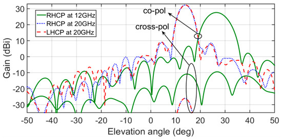
Figure 10.
Simulated radiation patterns in elevation plane at 12 GHz for RHCP and 20 GHz for both RHCP and LHCP provided by designed reflectarray that radiates three circular polarization focused beams.
We have analyzed this last design reflectarray by taking into account tolerance errors of 5% variation of permittivity (i.e., εr1 = εr2 = 2.31) and +/−0.05 mm variations of the lengths of dipoles and arcs. These tolerance errors are higher than typical for dielectric layers material [20] and tolerance errors of mechanical PCB milling [31] in order to include the worst-case manufacturing scenario. These variations of length have been randomly added in each element of reflectarray. In Figure 11, a comparison of the resultant radiation patterns taking into account the tolerance errors and radiation patterns obtained in the elevation plane of Figure 10 is shown:
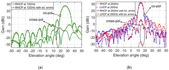
Figure 11.
Comparison between the simulated radiation patterns in the elevation plane shown in Figure 10 and the simulated radiation patterns that take into account the tolerance errors of permittivity and length variations of the dipoles and arcs. (a) At 12 GHz for RHCP. (b) At 20 GHz for both RHCP and LHCP.
According with the results shown in Figure 11a, the tolerance errors produce insignificant variation of the copolar radiation pattern at 12 GHz but a significant increment of cross-polar level is produced (from −10 dBi to −0.9 dBi of cross-polar gain). However, in Figure 11b the side lobe levels of copolar radiation patterns change at 20 GHz from 23.5 dB to 18 dB for RHCP and insignificant variation is produced for LHCP. The most significant variation is produced for cross-polar radiation patterns at 20GHz in both circular polarization when the cross-polar levels reach 5.7 dBi of cross-polar gain due to tolerance errors. In order to avoid these significant variations of cross-polar level we recommend that the permittivity of dielectric layers was measured previous design reflectarray design and manufacturing the designed reflectarray with high accuracy machines, such as protolaser machines [31]. Furthermore, in [17,18] measurements using similar reflectarray elements are provided (from 15 at 22 GHz in [17] and from 19.2 at 29.75 GHz in [18]) with acceptable results.
4. Conclusions
A two-layered reflectarray element is proposed consisting of a split ring surrounding two orthogonal sets of three parallel dipoles. This element makes it possible to design dual-band circular polarization reflectarrays radiating one circular polarization beam at Ku-band by means of VRT and two orthogonal circular polarization beams at Ka-band by ESVT for a satellite downlink. Rotations of split rings and different sizes of dipoles have been exploited as degrees of freedom by VRT and ESVT for designing focused beams dual band dual circular polarized reflectarrays. Until this work, these capabilities of the reflectarray element have been never exploited to focus the reflected beams in both circular polarizations for dual band applications. The split rings have been used to achieve single focused beam for circular polarization by VRT at 12 GHz, and the set of orthogonal dipoles have been used to achieve two focused beams for dual circular polarization by ESVT at 20 GHz.
The designed reflectarrays have been carried out under local periodicity assumption by means of in-house electromagnetic software that applies the Method of Moments in the Spectral Domain. Validations of the in-house electromagnetic software show significant CPU time savings with respect to CPU time consumption provided by commercial software of general purpose as CST electromagnetics software.
Parametric studies have shown when the dimensions of the split ring are adjusted by VRT at 12 GHz and then fix the dipoles lengths by ESVT at 20 GHz, the resultant cross-polar levels are lower than when first fixing the dipoles lengths at 20 GHz, and then adjusting the split rings at 12 GHz. In this way, the design procedure is based on two stages: First VRT is applied based on rotations of the split ring with arc lengths adjustment. Second, the design procedure at Ka-band uses the ESVT, and is based on adjustment of the dipole’s lengths for fixed values of the arc lengths/rotations obtained in the previous stage. Two different reflectarrays have been designed radiating RHCP at 12 GHz, and both RHCP and LHCP at 20 GHz, one of them with the same pointing direction at the two frequencies, and the other one with two different pointing directions. The simulated radiation patterns produced by reflectarrays show an efficiency around 65%, and a bandwidth of 6% for a main beam cross-polarization discrimination of 25 dB. The numerical results have been satisfactorily validated by CST software and tolerance errors study has been numerically carried out with acceptable results.
Author Contributions
Conceptualization, R.F., J.A.E.; methodology, R.F.; software, R.F., D.M.-d.-R., E.M.-d.-R. and R.R.B.; validation, R.F.; formal analysis, R.F. and R.R.B.; writing—original draft preparation, R.F.; writing—review and editing, R.F., J.A.E. and R.R.B.; visualization, R.F., D.M.-d.-R., E.M.-d.-R., J.A.E., R.R.B. and V.L.; supervision, J.A.E. and R.R.B.; project administration, J.A.E.; funding acquisition, J.A.E. All authors have read and agreed to the published version of the manuscript.
Funding
This work has been supported by the Spanish Ministry of Economy and Competitiveness under Project CICYT TEC2016-75103-C2-1-R, by the European Regional Development Fund (ERDF), by European Space Agency under ESTEC Contract No. 4000117113/16/NL/AF, and by “Junta de Andalucía” under Project P12-TIC-1435.
Conflicts of Interest
The authors declare no conflict of interest.
References
- Yun, S.H.; Yom, I.B. Four band feed system with electrical traking capability for Ku/Ka band bi directional antenna. In Proceedings of the 2008 IEEE Antennas and Propagation Society International Symposium, San Diego, CA, USA, 5–11 July 2008; pp. 1–4. [Google Scholar]
- Chang, Y.-C.; Hanlin, J. Commercial Ka and Ku bands reflector antennas. In Proceedings of the 2007 IEEE Antennas and Propagation Society International Symposium 2007, Honolulu, HI, USA, 9–15 June 2007; pp. 5175–5178. [Google Scholar] [CrossRef]
- Bhutani, A.; Schaefer, J.; Pauli, M.; Scherr, S.; Goettel, B.; Nierlich, M.; Zwick, T. 3D metal printed Ku/Ka Band modified turn-stile junction orthomode transducer. In Proceedings of the 2016 Asia-Pacific Microwave Conference, New Delhi, India, 5–9 December 2016; pp. 1–4. [Google Scholar]
- Huang, J.; Encinar, J.A. Reflectarray Antennas; Wiley: Piscataway, NJ, USA, 2008. [Google Scholar]
- Martinez-De-Rioja, E.; Encinar, J.A.; Florencio, R.; Boix, R.R. Dual polarized reflectarray antenna to generate independent beams in Ku and Ka bands. In Proceedings of the 2016 10th European Conference on Antennas and Propagation (EuCAP), Davos, Switzerland, 10–15 April 2016; pp. 1–5. [Google Scholar]
- Martinez-De-Rioja, E.; Encinar, J.A.; Florencio, R.; Boix, R.R. Reflectarray in K and Ka bands with independent beams in each polarization. In Proceedings of the 2016 IEEE International Symposium on Antennas and Propagation (APSURSI), Fajardo, Puerto Rico, 26 June–1 July 2016. [Google Scholar] [CrossRef]
- Martinez-De-Rioja, E.; Encinar, J.; Barba, M.; Florencio, R.; Boix, R.R.; Losada-Torres, V. Dual Polarized Reflectarray Transmit Antenna for Operation in Ku- and Ka-Bands With Independent Feeds. IEEE Trans. Antennas Propag. 2017, 65, 3241–3246. [Google Scholar] [CrossRef]
- Deng, R.; Xu, S.; Yang, F.; Li, M. An FSS-Backed Ku/Ka Quad-Band Reflectarray Antenna for Satellite Communications. IEEE Trans. Antennas Propag. 2018, 66, 4353–4358. [Google Scholar] [CrossRef]
- Huang, J.; Pogorzelski, R. A Ka-band microstrip reflectarray with elements having variable rotation angles. IEEE Trans. Antennas Propag. 1998, 46, 650–656. [Google Scholar] [CrossRef]
- Zhou, M.; Sørensen, S.B. Multi-spot beam reflectarrays for satellite telecommunication applications in Ka-band. In Proceedings of the 2016 10th European Conference on Antennas and Propagation (EuCAP), Davos, Switzerland, 10–15 April 2016; pp. 1–5. [Google Scholar]
- Smith, T.; Gothelf, U.V.; Kim, O.S.; Breinbjerg, O. Design, manufacturing, and testing of a 20/30 GHz dual-band circularly polarized reflectarray antenna in submission. IEEE Antennas Wireless Propag. Lett. 2013, 12, 1480–1483. [Google Scholar] [CrossRef]
- Deng, R.; Mao, Y.; Xu, S.; Yang, F. A Single-Layer Dual-Band Circularly Polarized Reflectarray With High Aperture Efficiency. IEEE Trans. Antennas Propag. 2015, 63, 1. [Google Scholar] [CrossRef]
- Smith, T.; Gothelf, U.V.; Kim, O.S.; Breinbjerg, O. An FSS-Backed 20/30 GHz circularly polarized reflectarray for a shared aperture L- and Ka-band satellite communication antenna. IEEE Trans. Antennas Propagat. 2014, 62, 661–668. [Google Scholar] [CrossRef]
- Pozar, D.M.; Metzler, T.A. Analysis of a reflectarray antenna using microstrip patches of different size. Electron. Lett. 1993, 29, 657–658. [Google Scholar] [CrossRef]
- Encinar, J. Design of two-layer printed reflectarrays using patches of variable size. IEEE Trans. Antennas Propag. 2001, 49, 1403–1410. [Google Scholar] [CrossRef]
- Florencio, R.; Encinar, J.A.; Boix, R.R.; Barba, M.; Toso, G. Flat Reflectarray That Generates Adjacent Beams by Discriminating in Dual Circular Polarization. IEEE Trans. Antennas Propag. 2019, 67, 3733–3742. [Google Scholar] [CrossRef]
- Martinez-de-Rioja, D.; Florencio, R.; Encinar, J.A.; Carrasco, E.; Boix, R.R. Dual frequency reflectarray cell to provide opposite phase-shift in dual circular polarization with application multibeam satellite antennas. IEEE Antennas Wireless Propag. Lett. 2019, 18, 1591–1595. [Google Scholar] [CrossRef]
- Martinez-de-Rioja, D.; Florencio, R.; Martinez-de-Rioja, E.; Arrebola, M.; Encinar, J.A.; Boix, R.R. Dual band reflectarray to generate to spaced beams in orthogonal circular polarization by variable rotation technique. IEEE Trans. Antennas Propag. 2020, 1–10, early access article. [Google Scholar] [CrossRef]
- Huo, Y.; Dong, X.; Xu, W.; Yuen, M. Enabling Multi-Functional 5G and Beyond User Equipment: A Survey and Tutorial. IEEE Access 2019, 7, 116975–117008. [Google Scholar] [CrossRef]
- Rogers Corporation. Available online: https://rogerscorp.com (accessed on 8 June 2020).
- Florencio, R.; Boix, R.R.; Carrasco, E.; Encinar, J.A.; Losada, V.; Losada-Torres, V. Efficient numerical tool for the analysis and design of reflectarrays based on cells with three parallel dipoles. Microw. Opt. Technol. Lett. 2013, 55, 1212–1216. [Google Scholar] [CrossRef]
- Florencio, R.; Boix, R.R.; Encinar, J.A. Efficient Spectral Domain MoM for the Design of Circularly Polarized Reflectarray Antennas Made of Split Rings. IEEE Trans. Antennas Propag. 2018, 67, 1760–1771. [Google Scholar] [CrossRef]
- Mittra, R.; Chan, C.H.; Cwik, T. Techniques for analyzing frequency selective surfaces-a review. Proc. IEEE 1988, 76, 1593–1615. [Google Scholar] [CrossRef]
- Mesa, F.; Marqués, R.; Horno, M. A general algorithm for computing the bidimensional spectral Green’s dyads in multilayered complex bianisotropic media: The equivalent boundary method. IEEE Trans. Microwave Theory Tech. 1991, 39, 1640–1649. [Google Scholar] [CrossRef]
- Rahmat-Samii, Y. Useful coordinate transformations for antenna applications. IRE Trans. Antennas Propag. 1979, 27, 571–574. [Google Scholar] [CrossRef]
- Florencio, R.; Boix, R.R.; Carrasco, E.; Encinar, J.A.; Barba, M.; Pérez-Palomino, G. Broadband reflectarrays made of cells with three coplanar parallel dipoles. Microw. Opt. Technol. Lett. 2014, 56, 748–753. [Google Scholar] [CrossRef]
- Florencio, R.; Encinar, J.; Boix, R.R.; Perez-Palomino, G. Dual-polarisation reflectarray made of cells with two orthogonal sets of parallel dipoles for bandwidth and cross-polarisation improvement. IET Microw. Antennas Propag. 2014, 8, 1389–1397. [Google Scholar] [CrossRef]
- CST Microwave Studio. Available online: www.cst.com (accessed on 8 June 2020).
- Thomas, F.E.; John, L.V. Antenna Engineering Handbook; McGraw-Hill: Piscataway, NY, USA, 2007. [Google Scholar]
- Zhou, M.; Sorensen, S.B.; Jorgensen, E.; Meincke, P.; Kim, O.S.; Breinbjerg, O. An Accurate Technique for Calculation of Radiation From Printed Reflectarrays. IEEE Antennas Wirel. Propag. Lett. 2011, 10, 1081–1084. [Google Scholar] [CrossRef]
- LPKF Laser and Electronics. Available online: https://www.lpkf.com (accessed on 8 June 2020).


© 2020 by the authors. Licensee MDPI, Basel, Switzerland. This article is an open access article distributed under the terms and conditions of the Creative Commons Attribution (CC BY) license (http://creativecommons.org/licenses/by/4.0/).