Abstract
With the increasing penetration of distributed generators, various operational problems, especially severe voltage violation, threaten the secure operation of active distribution networks. To effectively cope with the voltage fluctuations, novel controllable power electronic equipment represented by soft open points has been used in active distribution networks. Meanwhile, the communication has dramatically increased due to the rise of the variety and number of devices within the network. This paper proposes a decentralized voltage control method of soft open points based on voltage-to-power sensitivity. The method reduces the burden of communication, storage, and calculation effectively in a decentralized manner and fulfills the rapid requirements of large-scale active distribution networks. First, the network is divided into several sub-areas; each is under the control of one soft open point at most. The initial strategies of soft open points are adjusted by local voltage-to-power sensitivity and the voltage information within the sub-areas. If some nodal voltages still exceed the expected range after the sub-area autonomy, the operation strategies of soft open points are further improved by inter-area coordination with the alternating direction method of multipliers algorithm. The effectiveness of the proposed decentralized control method is verified on the IEEE 33-node system.
1. Introduction
The growing penetration of distributed generators (DGs), such as wind turbines (WTs) and photovoltaics (PVs), brings a series of operational problems to active distribution networks (ADNs), especially severe voltage violation [1,2]. Novel power electronic equipment represented by soft open points (SOPs) can effectively cope with the problems through accurate active and reactive power flow controls. SOPs are usually installed to replace a normally open point (NOP) for a flexible connection between feeders in ADNs. Compared to conventional regulation devices, such as shunt capacitors, on-load tap changers (OLTCs) and static var compensator (SVCs), SOPs can conduct a fast and precise active and reactive power flow adjustment. Therefore, it is of great significance to integrate SOPs in ADNs to realize a rapid and flexible operation control [3,4,5,6].
Previous studies mainly focused on the central control or local control manners [7,8,9]. However, for centralized control, the central controller needs to collect the information of the whole physical system and the external environments of ADNs. With the remarkable rise in the number and variety of devices in ADNs, the amount of data required for centralized control has dramatically increased, which causes a much heavier burden on communication, storage, and computation. Moreover, in terms of privacy and security, the centralized manner can be influenced by potential data unavailability [10]. Besides, since there is only one control center in this manner, the system is susceptible to faults at the central controller, which does not fulfill the operation reliability requirements of ADNs. On the other hand, the local control manner is simply based on local information [9], which reduces communication traffic effectively. However, it is hard to obtain a global optimized result because of the incomplete information.
In contrast, decentralized control is well-known for its excellent scalability, high robustness, low bandwidth communication, and efficient computation [10,11]. It decomposes the optimization problem into smaller sub-problems by partitioning the system into several sub-areas, each of which is under the control of a local controller. Meanwhile, it introduces a coordination scheme to realize a more approximate global optimization than the local manner. Therefore, decentralized control can well satisfy the rapid and reliable control requirements of large-scale ADN operation optimization and will become the focus of SOP operation control in the future.
In previous studies, decentralized control was widely adopted in various operation scenarios of power and energy systems. Ref. [12] proposed a real-time decentralized control algorithm in multi-area ADN relying only on dispersed battery energy storage systems (BESSs). Ref. [13] designed a decentralized economic operation control scheme for a hybrid alternating current (AC)/direct current (DC) microgrid. It consisted of economic power sharing and economic power interaction between sub-grids to realize economic power sharing among all DGs and economic power interaction between sub-grids. In [14], a bi-level decentralized control for a large-scale wind farm cluster (WFC) was developed. By distributing the computation and monitoring tasks to several wind farm controllers, the model effectively reduces the communication cost and computation burden. In terms of SOP, our previous work [15] proposed a combined decentralized and local voltage control strategy of SOPs, where the active power and reactive power of SOPs are adjusted separately. A fully decentralized framework is expected to further lighten the communication burdens, and to realize the plug-and-play of SOPs in the future.
Former studies realized SOP-based voltage control mainly with non-linear power flow constraints, which require a relatively long calculation time to solve. By introducing the concept of voltage-to-power sensitivity, conducting a numerical linearization around the operating point, a linear relationship between node power injection and voltage is established to improve the calculation efficiency. Voltage-to-power sensitivity has a clear physical concept that shows the relation of active or reactive power fluctuation in voltage amplitude, which currently has been widely applied in stability analysis [16,17], voltage regulation [18,19], DG hosting capacity [20], optimal allocation [21], and so on. Furthermore, with the development of advanced measurement equipment in distribution networks, such as the micro phasor measurement unit (μPMU), sensitivities can be obtained based on limited measurements [17,22]. Thus, when the ADN is divided into several sub-areas, each sub-area can obtain the voltage-to-power sensitivity simply based on the information inside the sub-area to realize decentralized control.
Therefore, to reduce data traffic and fulfill the rapid requirements of large-scale ADNs, this paper proposes a decentralized voltage control method of SOPs based on voltage-to-power sensitivity. The main contributions of the paper are summarized as follows:
(1) An ADN partitioning method centered on SOPs is proposed. Traditional partitioning strategies consider DGs as the partition centers or SOPs as the boundary. In comparison, taking SOP as the center of the sub-area could utilize its powerful control ability on the nodes and branches in the sub-area as deeply as possible, as well as reduce the computational burden more reasonably.
(2) An intra-area voltage control model is established based on voltage-to-power sensitivity. To reduce communication and calculation burden, this paper proposes a decentralized voltage control model for SOPs in ADNs. Voltage-to-power sensitivity is introduced to each sub-area in the decentralized control model to further linearize the model and improve the efficiency of the optimization calculation.
(3) Both the boundary information and the selected important non-boundary information in each sub-area interact with adjacent sub-areas under inter-area coordinated control. Namely, the operation information of SOPs integrated into non-boundary nodes is considered to be reflected at the boundary, based on sensitivity analysis, to approach the global optimization performance as close as possible.
The remainder of this paper is organized as follows. Section 2 presents the framework of decentralized voltage control strategies of SOPs. Section 3 builds an intra-area autonomous voltage control model of SOPs, and the inter-area voltage coordinated control model is established in Section 4. Section 5 presents the results and discussion of the IEEE 33-node system to verify the effectiveness of the proposed method. Finally, Section 6 concludes the paper.
2. Framework of Sensitivity-Based Decentralized Voltage Control of SOPs
First, the ADN is decomposed into several sub-areas based on electricity distance, and each area is under the control of one SOP at most. Taking each control period as a unit, the SOP operation strategies of each sub-area in the current period are initially adjusted using intra-area measurements and corresponding voltage-to-power sensitivity of the nodes inside the sub-area. The mutual influences among sub-areas are ignored in the first autonomous control stage. If some nodal voltages are still beyond the expected range after the sub-area autonomy, the operation strategies of SOPs can be improved by further inter-area coordination through boundary information interaction. The inter-area coordination control mode is based on the alternating direction method of multipliers (ADMM) algorithm, in which the influence of the SOP in each sub-area is transferred to the boundary nodes by voltage-to-power sensitivities and interacts with the adjacent sub-areas as boundary information. In summary, the proposed decentralized control framework of SOPs is shown in Figure 1.
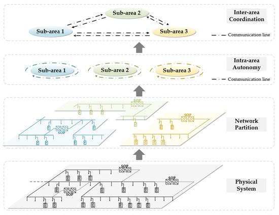
Figure 1.
Decentralized control framework of SOPs.
3. Intra-area Autonomous Voltage Control of SOPs
This section proposes a sensitivity-based intra-area autonomous voltage control method to reduce communication and calculation burden and improve the system operation performance. The operation strategies of SOPs in each sub-area are obtained only by intra-area measurements and corresponding voltage-to-power sensitivity of the nodes inside the sub-area.
3.1. Network Partition
The partition of the ADN can be described as a clustering problem. The central nodes of each sub-area are regarded as the clustering centers, and the electrical distance between the nodes is considered as clustering basis. Since this paper focuses on the optimization control of SOPs for ADNs, partitioning the network centered on SOP can fully utilize its ability of voltage and power flow regulation while reducing the computational complexity. Thus, under this partition principle, there is one SOP at most in each sub-area.
In this paper, the clustering method in [23] is used to divide the ADN with SOPs. Considering that the optimal number of sub-areas of the ADN may be inconsistent with the number of SOPs in the system, to ensure that each sub-area contains one SOP at most, the number of divided sub-areas is defined as:
where is given by the distribution system operator (DSO) or refers to the empirical value [24]. indicates that the elements of “” round to the nearest integer less than or equal to “”. is the total number of the nodes in the ADN, and represents the total number of SOPs integrated in the system. This paper considers an SOP with two terminals. Therefore, during the clustering calculation, two terminals of one SOP are selected separately as two clustering centers. After the clustering result is obtained, two sub-areas of the terminal nodes are merged into one sub-area under the control of the related SOP. Then, the number of cluster centers is determined by (2).
For each node , the local density and its distance from nodes of higher density are defined by the electrical distance as [23]:
where represents the threshold value of the electricity distance. if , and otherwise. is the set of all nodes in the ADN, and is the set of all integration nodes of SOPs. denotes the set of all nodes whose local density is larger than node . The electricity distance between nodes and is defined as follows [25].
where and are the electrical distance between nodes and defined in terms of the relation between nodal voltage and active/reactive power injection, respectively. The weight coefficients and describe the different influence of active and reactive power to nodal voltage. and represent the overall line resistance and reactance of the overlapped part of the unique path from the source node to node and the unique path from the source node to node [26]. and can also be regarded as the approximate voltage-to-active-power sensitivity and voltage-to-reactive-power sensitivity, respectively, which depend only on the physical topology of the network.
Since the cluster centers are assumed to be a relatively long distance from other points with a higher local density and to be surrounded by neighbor nodes with lower local density, nodes with high and long should be selected as the center nodes. Thus, in order to guarantee that the terminal nodes of SOPs are selected, their local density and distance are set to:
where 100 is an empirical value that ensures the value stands out but is not too far from the database. In this case, must be a subset of the set of all cluster centers . A comprehensive index for identifying central nodes is proposed as follows; nodes with a large index value are selected as cluster centers.
In summary, the steps of partitioning include: a) determine and according to (1) and (2); b) select the central nodes based on (3)–(10) and assign each remaining node to the cluster of its nearest neighbor with a higher density; and c) combine the two sub-areas centered at the two terminal nodes of SOPs.
3.2. Model of Intra-area Voltage Control
In the stage of initial autonomous voltage control, the minimum voltage deviation in each sub-area is taken as the objective function:
where is the set of nodes in sub-area , represents the nodal voltage magnitude at node in time period . is the desired voltage range.
In time period , the assumption is made that there is no variation in active or reactive power at all nodes, except power injections of SOPs. Then, the voltage magnitude at node can be calculated according to its original value before the intra-area autonomy and corresponding voltage-to-power sensitivity.
where is the set of terminal nodes of the SOP integrated in sub-area . and are active and reactive power injection variations of the SOP at node in time period . denotes voltage-to-active-power sensitivity between and . denotes voltage-to-reactive-power sensitivity between and . and represent active and reactive power injection at node in time period . Specifically, and are calculated for every time period using real-time local measurements of the deviation of nodal voltage magnitude to unit changes in nodal active or reactive power output [27]. Alternatively, if there are μPMUs in the system, the sensitivities can also be estimated via network equivalents with μPMU measurements [17]. The nodal voltages should satisfy their operation constraints as below:
where denotes the operation range of nodal voltage.
In addition, SOP operation constraints should be included. The control variables of SOPs under intra-area autonomous control are and , the variation of active and reactive power of the SOP at node in time period .
where and represent active and reactive power injection of the SOP at node in time period . and denote active and reactive power injection of the SOP before intra-area autonomy at node in time period . The loss constraint of SOPs is as follows:
where represents the active power loss of the SOP at node in time period . The active power transition constraints and capacity constraints of the SOP integrated between node and are given in Equations (18)–(25) [5]:
where is the loss coefficient of the SOP at node . represents the capacity of the SOP at node . and denote the absolute value of maximum active and reactive power injection of the SOP at node .
In summary, the autonomous control model of SOPs can be concluded as (26). denotes the equality constraints in sub-area , including Equations (13), (15)–(17) of local variables in time period . denotes the inequality constraints in sub-area including Equations (14), (18)–(25). The proposed model is a second-order cone programing model that can be solved by commercial optimization software such as CPLEX and MOSEK.
4. Inter-area Coordinated Voltage Control of SOPs
In the stage of autonomous voltage control, operation strategies of SOPs are conducted based simply on the measurements inside the sub-areas to reduce data traffic and the calculation scale. However, it may be hard to fulfill the requirement of global optimization since the operation state of SOPs located in other sub-areas is not accounted for, especially in the neighboring ones. Therefore, this section proposes a coordinated control model based on the ADMM algorithm. The operation condition of the SOP in the current sub-area can be transferred to the boundary nodes by voltage-to-power sensitivities and interacts with the adjacent sub-areas as boundary information.
4.1. Boundary Information for Interaction
This section conducts the information interaction for inter-area coordination at boundary nodes using nodal voltage-to-power sensitivities obtained from local measurements. By exchanging the information through boundary nodes, the inter-area optimization of each sub-area can be well linked to the global one.
However, based on the partition method in Section 3.1, the boundary between two sub-areas is a branch. Thus, we choose the end node of the boundary branch as the boundary node of the two neighboring sub-areas in the inter-area coordination. For the boundary node between sub-area and , the local information of the SOP in sub-area for interacting to sub-area through boundary node is calculated according to (27) and (28):
where is the set of boundary nodes of sub-area . The nodal voltage magnitude in sub-area can be calculated as:
where is the voltage magnitude before inter-area coordination at node in period . is the set of neighboring sub-areas of sub-area . Not only the SOP located in the certain sub-area but also SOPs in its adjacent sub-areas are taken into account to obtain an approximate global optimization in a decentralized way. For sub-area , the variations of active and reactive power at boundary node between sub-area and for interaction are:
4.2. Model of Inter-area Voltage Control
Based on the autonomous control model of SOPs, this section establishes a coordinated control model of SOPs based on a fully decentralized form of the ADMM algorithm [15,28] aiming at a globally optimal solution. Each sub-area collects the local nodal voltage information and corresponding voltage-to-power sensitivities and then forms an interaction of operation variables with the adjacent sub-area through boundary nodes.
where represents the objective function of each sub-area. and denote the inequality and equality constraints in sub-area proposed in Section 3.2 and Section 4.1. is the iteration index. can be expressed as . The iterations consist of the following two steps:
where denotes the feasible region of state vector in area . denotes the set of all sub-areas include node . is an auxiliary variable that represents in the standard form of ADMM in which is the global variable of node in time period and is the local Lagrangian multiplier corresponding to node in sub-area in the th iteration. The penalty factor is refreshed by:
where and are the preset parameters. is defined as the original residual of the feasibility of the original problem, and is defined as the dual residual of the feasibility of the dual problem. The criterion for iterative convergence can be determined by (36) [28]:
where is the border residual in the th iteration. is the given tolerance. The flowchart of the proposed decentralized voltage control strategy of SOPs is shown in Figure 2.
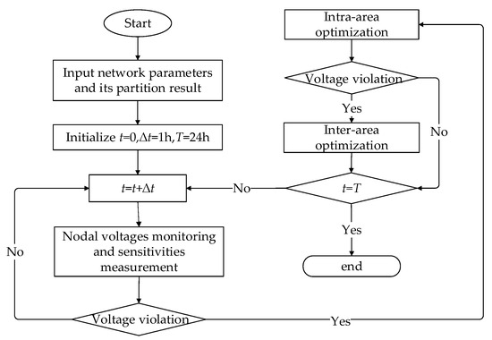
Figure 2.
Flowchart of the proposed decentralized control strategy of SOPs.
5. Results and Discussion
In this section, the effectiveness of the proposed control strategy of SOPs is verified on the IEEE 33-node system. The model is implemented in the YALMIP optimization toolbox [29] using MATLAB R2014a and is solved by IBM ILOG CPLEX 12.60. The numerical experiments were carried out on a Windows 10 computer equipped with an Intel(R) Xeon(R) CPU E5-1620 processor running at 3.70 GHz, 8 GB of RAM.
5.1. Result of the Partition
Figure 3 exhibits the modified IEEE 33-node system [30], of which the rated voltage level is 12.66 kV. The total active and reactive power loads of the system are 3715 kW and 2300 kVar, respectively. One PV and two WTs are integrated into the system. Table 1 presents the detailed installation parameters of DGs.
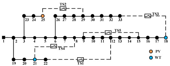
Figure 3.
Diagram of the modified IEEE 33-node system.

Table 1.
Detailed installation parameters of DGs.
Given the remarkable development in power electronics technologies, SOPs are gradually being widely used in ADNs. Therefore, this section replaces tie switches TS 1 to TS 4 by SOPs, each with a capacity of 500 kVA. The loss coefficient of each inverter for the SOP is set to 0.02.
According to Equation (1), the number of sub-areas is set to 4, and the number of cluster centers is 8 according to Equation (2), which means every sub-area contains a single SOP. Nodes 8, 12, 18, 21, 22, 25, 29, and 33 are selected as cluster centers by Equations (3)–(10), colored in blue, as shown in Figure 4. Table 2 presents the distribution result of nodes. Then, nodes in each line in Table 2 are gathered into one cluster since this paper considers two sub-areas centered at two terminal nodes of a certain SOP as one.
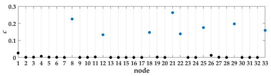
Figure 4.
Decision graph with four SOPs integrated in the system.
Table 2.
Detailed distribution result of nodes.
Overall, the partitioning result of the system with four SOPs is shown in Figure 5. Nodes 10, 17, 22, 25, 28, and 31 are selected as boundary nodes in inter-area coordination. The total numbers of nodes and branches are relatively small, and the calculation scale is reduced effectively.
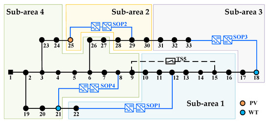
Figure 5.
Partitioning result of the modified IEEE 33-node system.
5.2. Analysis of Optimization Results
Four scenarios are adopted to verify the effectiveness of the proposed decentralized control method of SOPs.
Scenario 1: There is no control strategy conducted on SOPs, and the initial operation state of ADNs is obtained.
Scenario 2: The proposed intra-area autonomous control of SOPs is conducted.
Scenario 3: The proposed autonomous and coordinated control of SOPs is conducted.
Scenario 4: SOPs are centralized controlled to realize the global operation optimization of ADNs based on the method in ref. [5].
Taking an hourly time step over a day, the daily DG and load operation curves are obtained by forecasting, as shown in Figure 6. It is assumed that the range of statutory voltage is [0.90,1.10]. The desired voltage range is set from 0.98 p.u. to 1.02 p.u., which is also the margin of threshold in the coordinated control stage. The penalty factor is initially set to 104 in the ADMM algorithm, and and are set to 1.0 and 0.1, respectively. The predetermined tolerance ε is set as 0.001 to ensure convergence and to speed up the calculation.
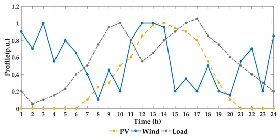
Figure 6.
Daily operation curve of DGs and loads.
5.2.1. Optimization Results
To consider the severe voltage violation as a result of high penetration of DGs in ADNs, we set the power factors of the DGs to 1.0, and every DG operates at its full capacity. The total active power penetration of DGs reaches 100%.
Figure 7 displays the values of nodal voltages, and Figure 8 shows the operation strategies of four SOPs. Table 3 presents the optimization results of the four scenarios. In scenario 1, there is severe voltage violation in the system without the control of SOPs. From Figure 7a, voltage magnitudes at node 18 exceed both the upper and lower desired level initially in scenario 1. Then, after the intra-area autonomous control in scenario 2, voltage violation is significantly mitigated. The operation strategies of SOPs are modified further by inter-area coordination through boundary information interaction in scenario 3 when voltage violations still occur, namely, in time periods 6, 10–14, 17, and 22, as shown in Figure 8. After the coordination in scenario 3, voltage profiles perform much better and more closely approximate the global optimization in scenario 4, as established in Figure 7c. Therefore, given that the proposed method in scenario 3 is based on less measurement information, the proposed decentralized control strategy of SOPs can effectively mitigate voltage violations without a huge communication and calculation burden.
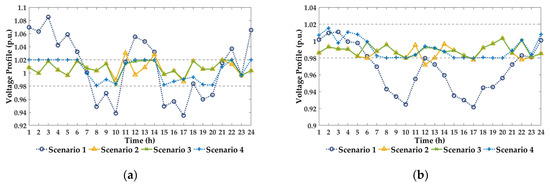
Figure 7.
(a) Voltage profile of node 18. (b) Voltage profile of node 31. (c) Voltage profile of the system with four SOPs at 5 pm.
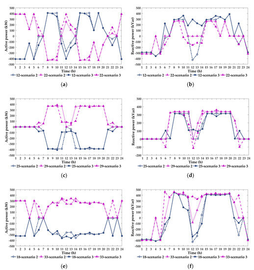
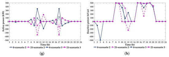
Figure 8.
(a) Operation strategy of the active power of SOP integrated at nodes 12 and 22. (b) Operation strategy of the reactive power of SOP integrated at nodes 12 and 22. (c) Operation strategy of the active power of SOP integrated at nodes 25 and 29. (d) Operation strategy of the reactive power of SOP integrated at nodes 25 and 29. (e) Operation strategy of the active power of SOP integrated at nodes 18 and 33. (f) Operation strategy of the reactive power of SOP integrated at nodes 18 and 33. (g) Operation strategy of the active power of SOP integrated at nodes 8 and 21. (h) Operation strategy of the reactive power of SOP integrated at nodes 8 and 21.
Table 3.
Performance comparison of the four scenarios.
5.2.2. Discussion on the Impact of the DG Penetration
In this section, the DG penetration was varied from 0 to 140% to show the role and performance of inter-area coordination in decentralized control. The power factors of the DGs were all set to 1.0. Scenarios 1, 2, and 3 designed above were adopted in this section.
Figure 9 displays the variation in the number of inter-area coordination control times in scenario 3 with different penetration levels. Since DGs were integrated to the end of the branch where nodal voltages decreased sharply in the initial condition, they are helpful to compensate the imbalance between the power supply and load demand to increase the voltage magnitude. Therefore, along with the rise of the penetration from zero, the frequency of coordination decreased initially. However, when the penetration continuously increased, some magnitudes of nodal voltage were no longer lower than the desired range but exceeded the upper limit. SOPs in these sub-areas could not adequately distribute the surplus power in the stage of intra-area autonomous control. Hence, inter-area coordination became more frequent to further regulate the power flow with adjacent sub-areas through information interaction. Figure 10 shows the maximum and minimum values of nodal voltages with various penetrations of DGs. The inter-area autonomous control eliminated voltage violations effectively, while the inter-area coordination became more important with increasing DG penetration.
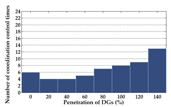
Figure 9.
Number of coordination control times in scenario 3 with different DG penetrations.
Figure 10.
Voltage ranges with different DG penetrations.
6. Conclusions
This paper proposes a decentralized voltage control method of SOPs based on voltage-to-power sensitivity to reduce data traffic and fulfill the rapid and reliable control requirements of large-scale ADNs. First, the network is divided into several sub-areas, each of which is under the control of one SOP at most. The initial strategies of SOPs are adjusted by using local voltage-to-power sensitivity and voltage information within the sub-areas. If nodal voltages still exceed the expected range after the intra-area autonomy, the operation strategies of SOPs are further improved by inter-area coordination with the ADMM algorithm. The effectiveness of the proposed decentralized control method is verified on the case studies of the IEEE 33-node system.
With the rapid development of power electronic technology, it is foreseeable that the applications of SOPs will become more and more extensive. The proposed method shows great potential in applications with different integration conditions of DGs, the plug-and-play of SOPs, and the multi-time scale control scheme in ADNs. Additionally, based on limited measurements, sensitivities will be easier to be obtained and will be more precise with the promotion of advanced measurement equipment and technology in the future. The operation strategy based on sensitivities will be more efficient, and the relative error between the solutions of central and decentralized control manners will be further reduced.
Author Contributions
All authors have read and agree to the published version of the manuscript. Conceptualization, J.Z. and P.L.; methodology, J.Z. and M.Y.; software and formal analysis, H.J., M.Y., H.Y., and G.S.; writing—original draft preparation, M.Y.; review and editing, H.Y., G.S., and H.J.; supervision, J.Z. and P.L.; funding acquisition, J.Z. and P.L.
Funding
This research was funded by the National Natural Science Foundation of China under grant numbers U1866207 and 51977139.
Conflicts of Interest
The authors declare no conflict of interest.
Nomenclature
| Sets | |
| Set of all nodes | |
| Set of all nodes whose density is larger than node | |
| Set of all integration nodes of SOPs | |
| Set of all cluster centers | |
| Set of nodes in sub-area | |
| Set of integration nodes of the SOP in sub-area | |
| Set of boundary nodes of sub-area | |
| Set of neighboring sub-areas of sub-area | |
| Set of local variables in sub-area under intra-area control in time period | |
| Set of local variables under inter-area control in the th iteration in time period | |
| Set of all sub-areas that include node | |
| Indices | |
| Indices of nodes, from 1 to | |
| t | Index of time period |
| , | Indices of sub-areas |
| k | Index of iteration |
| Variables | |
| Number of divided sub-areas | |
| Number of cluster centers | |
| Electrical distance from node to node | |
| Electrical distance threshold | |
| Electrical distance from node to node defined in terms of the relation between active power injection and nodal voltage | |
| Electrical distance from node to node defined in terms of the relation between reactive power injection and nodal voltage | |
| Local density of node | |
| Distance of nodes with a higher density than node | |
| Comprehensive index for identifying center nodes | |
| Voltage magnitude at node in time period | |
| Original voltage magnitude at node in period | |
| Voltage-to-active-power sensitivity between and | |
| Voltage-to-reactive-power sensitivity between and | |
| Active and reactive power injection variation of the SOP at node in time period | |
| , | Active and reactive power injection at node in time period |
| Active and reactive power injection of the SOP at node | |
| , | Original value of active and reactive power injection of the SOP at node in time period |
| Active power loss of the SOP at node in time period | |
| Loss coefficients of the SOP integrated at node | |
| , | Variation of active and reactive power at boundary node of sub-area in time period |
| Local information of the SOP in sub-area at boundary node in time period | |
| Voltage magnitude at node in the th iteration in time period | |
| Active and reactive power injection variation of the SOP at node in the th iteration in time period | |
| Variation of active and reactive power for interaction at boundary node of sub-area in the th iteration in time period | |
| Local auxiliary vector for node in the th iteration in sub-area in time period | |
| Global variable of node in the th iteration in time period | |
| Local Lagrangian multiplier corresponding to node in sub-area in the kth iteration in time period | |
| Penalty factor in the th iteration | |
| Original residual vector of the feasibility of the original problem in the th iteration | |
| Dual residual vector of the feasibility of the dual problem in the th iteration | |
| Parameters | |
| Total number of nodes | |
| Theoretical maximum number of sub-areas | |
| Total number of SOPs integrated | |
| Overall line resistance of the overlapped part of the unique path from the source node to node and the unique path from the source node to node | |
| Overall line reactance of the overlapped part of the unique path from the source node to node and the unique path from the source node to node | |
| Weight coefficient | |
| Upper/lower limit of desired voltage range | |
| , | Upper/lower limit of system voltage |
| , | The absolute value of the maximum variation of active and reactive power of SOPs |
| Capacity of the SOP at node | |
| , | The absolute value of maximum active and reactive power injection of the SOP at node |
| Feasible region of state vector in sub-area | |
| Preset parameters in the ADMM algorithm | |
| Border residual in the th iteration | |
| Given tolerance for convergence |
References
- Barr, J.; Majumder, R. Integration of distributed generation in the Volt/VAR management system for active distribution networks. IEEE Trans. Smart Grid 2015, 6, 576–586. [Google Scholar] [CrossRef]
- Al-Jaafreh, M.A.A.; Mokryani, G. Planning and operation of LV distribution networks: A comprehensive review. IET Energy Syst. Integr. 2019, 1, 133–146. [Google Scholar] [CrossRef]
- Bloemink, M.; Green, T.C. Benefits of distribution-level power electronics for supporting distributed generation growth. IEEE Trans. Power Del. 2013, 28, 911–919. [Google Scholar] [CrossRef]
- Cao, W.; Wu, J.; Jenkins, N. Operating principle of soft open points for electrical distribution network operation. Appl. Energy 2016, 164, 245–257. [Google Scholar] [CrossRef]
- Li, P.; Ji, H.; Wang, C.; Zhao, J.; Song, G.; Ding, F.; Wu, J. Coordinated control method of voltage and reactive power for active distribution networks based on soft open point. IEEE Trans. Sustain. Energy 2017, 8, 1430–1442. [Google Scholar] [CrossRef]
- Qi, Q.; Wu, J.; Long, C. Multi-objective operation optimization of an electrical distribution network with soft open point. Appl. Energy 2017, 208, 734–744. [Google Scholar] [CrossRef]
- Long, C.; Wu, J.; Thomas, L. Optimal operation of soft open points in medium voltage electrical distribution networks with distributed generation. Appl. Energy 2016, 184, 427–437. [Google Scholar] [CrossRef]
- Ji, H.; Wang, C.; Li, P.; Zhao, J.; Song, G.; Ding, F.; Wu, J. A centralized-based method to determine the local voltage control strategies of distributed generator operation in active distribution networks. Appl. Energy 2018, 228, 2024–2036. [Google Scholar] [CrossRef]
- Li, P.; Ji, H.; Song, G.; Yao, M.; Wang, C.; Wu, J. A combined central and local voltage control strategy of soft open points in active distribution networks. Energy Proc. 2019, 158, 2524–2529. [Google Scholar] [CrossRef]
- Antoniadou-Plytaria, K.E.; Kouveliotis-Lysikatos, I.N.; Georgilakis, P.S.; Hatziargyriou, N.D. Distributed and decentralized voltage control of smart distribution networks: Models, methods, and future research. IEEE Trans. Smart Grid 2017, 8, 2999–3008. [Google Scholar] [CrossRef]
- Abedalsalam, B.A.; Mohammad, R.; Adel, N.; Hosseini, H. Reliability analysis of a decentralized microgrid control architecture. IEEE Trans. Smart Grid 2019, 10, 3910–3918. [Google Scholar]
- Bahramipanah, M.; Torregrossa, D.; Cherkaoui, R. A decentralized adaptive model-based real-time control for active distribution networks using battery energy storage systems. IEEE Trans. Smart Grid 2018, 9, 3406–3418. [Google Scholar] [CrossRef]
- Yang, P.; Yu, M.; Wu, Q.; Hatziargyriou, N.; Xia, Y.; Wei, W. Decentralized bidirectional voltage supporting control for multi-mode hybrid AC/DC microgrid. IEEE Trans. Smart Grid 2019. [Google Scholar] [CrossRef]
- Huang, S.; Wu, Q.; Guo, Y. Bi-level decentralised active power control for large-scale wind farm cluster. IET Renew. Power Gen. 2018, 12, 1486–1492. [Google Scholar] [CrossRef]
- Li, P.; Ji, H.; Yu, H.; Zhao, J.; Wang, C.; Song, G.; Wu, J. Combined decentralized and local voltage control strategy of soft open points in active distribution networks. Appl. Energy 2019, 241, 613–624. [Google Scholar] [CrossRef]
- Urquidez, A.O.; Xie, L. Singular value sensitivity based optimal control of embedded VSC-HVDC for steady-state voltage stability enhancement. IEEE Trans. Power Syst. 2016, 31, 216–225. [Google Scholar] [CrossRef]
- Yang, Y.; Zhao, J.; Liu, H.; Qin, Z.; Deng, J.; Qi, J. A matrix-perturbation-theory-based optimal strategy for small-signal stability analysis of large-scale power grid. Prot. Control Mod. Power Syst. 2018, 3, 34. [Google Scholar] [CrossRef]
- Su, H.; Li, P.; Li, P.; Fu, X.; Yu, L.; Wang, C. Augmented sensitivity estimation-based voltage control strategy of active distribution networks with PMU measurement. IEEE Access 2019, 7, 44987–44997. [Google Scholar] [CrossRef]
- Sami, S.S.; Cheng, M.; Wu, Z.; Jenkins, N. A virtual energy storage system for voltage control of distribution networks. CSEE J. Power Energy Syst. 2018, 4, 146–154. [Google Scholar] [CrossRef]
- Xu, Z.; Zhao, B.; Ding, M.; Zhou, J.; Wei, L. Photovoltaic hosting capacity evaluation of distribution networks and inverter parameters optimization based on node voltage sensitivity. Proc. CSEE 2016, 36, 1578–1587. [Google Scholar]
- Li, Z.; Chen, S.; Fu, Y.; Dong, C.; Zhang, J. Optimal allocation of ESS in distribution network containing DG base on timing-voltage sensitivity analysis. Proc. CSEE 2017, 37, 4630–4640. [Google Scholar]
- Hakerighadi, B.; Aminifar, F.; Afsharnia, S. Power systems wide-area voltage stability assessment considering dissimilar load variations and credible contingencies. J. Mod. Power Syst. Clean Energy 2019, 7, 78–87. [Google Scholar] [CrossRef]
- Rodriguez, A.; Laio, A. Clustering by fast search and find of density peaks. Science 2014, 344, 1492–1496. [Google Scholar] [CrossRef]
- Ma, J.; Tang, W.; Xu, S. State estimation of active distribution network based on multi-criteria partition and WLS-PDIPM algorithm. Autom. Electr. Power Syst. 2016, 12, 28–36. [Google Scholar]
- Chai, Y.; Guo, L.; Wang, C. Network partition and voltage coordination control for distribution networks with high penetration of distributed PV units. IEEE Trans. Power Syst. 2018, 33, 3396–3407. [Google Scholar] [CrossRef]
- Zhou, X.; Chen, L.; Farivar, M. Reverse and forward engineering of local voltage control in distribution networks. arXiv 2018, arXiv:1801.02015. [Google Scholar]
- Zhang, Z.; Ochoa, L.F.; Valverde, G. A novel voltage sensitivity approach for the decentralized control of DG plants. IEEE Trans. Power Syst. 2018, 33, 1566–1576. [Google Scholar] [CrossRef]
- Zheng, W.; Wu, W.; Zhang, B. A Fully distributed reactive power optimization and control method for active distribution networks. IEEE Trans. Smart Grid 2016, 7, 1021–1033. [Google Scholar] [CrossRef]
- Lofberg, J. Yalmip: A toolbox for modeling and optimization in MATLAB. In Proceedings of the 2004 IEEE International Conference on Robotics and Automation (IEEE Cat. No.04CH37508), New Orleans, LA, USA, 2–4 September 2004. [Google Scholar]
- Baran, M.E.; Wu, F. Optimal capacitor placement on radial distribution systems. IEEE Trans. Power Del. 1989, 4, 725–734. [Google Scholar] [CrossRef]
© 2020 by the authors. Licensee MDPI, Basel, Switzerland. This article is an open access article distributed under the terms and conditions of the Creative Commons Attribution (CC BY) license (http://creativecommons.org/licenses/by/4.0/).