Abstract
Asymmetric Cascaded H-bridge (ACHB) level inverters can output more voltage waveforms with fewer cascaded units while ensuring the quality of output voltage waveforms, so they have attracted more and more attention. Taking the topology of Type-III asymmetric CHB multilevel inverters as the research object, a Modified Hybrid Frequency Pulse Width Modulation (MHF-PWM) strategy is proposed in this paper. This modulation strategy overcomes the local overshoot of low-voltage unit in the presence of traditional Hybrid Frequency Pulse Width Modulation (HF-PWM), thus completely eliminating the low frequency harmonics in the output voltage waveform of Type-III ACHB nine-level inverters, and the Total Harmonic Distortion (THD) of output line voltage of the modulation strategy is lower than that of PS-PWM strategy in the whole modulation degree, which effectively improves the quality waveform of the output line voltage. At the same time, the strategy can also improve the problems of current backflow and energy feedback caused by the high-voltage unit pouring current to the low-voltage unit, thereby reducing the imbalance of the output power of the high-voltage and low-voltage units. Finally, the Matlab/Simulink simulation model and experimental platform are established to verify the validity and practicality of the modulation strategy.
1. Introduction
The Cascaded H-bridge (CHB) multilevel inverter is one of the most common multilevel inverter topologies, and has been widely used in medium voltage high-power inverters and Asymmetric Cascaded (AC) drive industry. CHB multilevel inverters are characterized by many output voltage levels, excellent harmonic performance, high transmission power, and easy modular design and manufacture [1,2,3,4,5]. With the development of multilevel technology, hybrid cascaded multilevel inverters have been widely used. Based on the traditional symmetric CHB topology, a new Asymmetric Cascaded H-bridge (ACHB) multilevel inverter topology is proposed by Manjreka et al. [6]. According to the difference of the DC source amplitude ratio of the cascading unit, the topology can be divided into two types: Type-II and Type-III ACHB multilevel inverters [7]. The topology can output more levels in the same cascade unit, so it can reduce the number of power switch devices and DC power supply in the same voltage level, and at the same time, it can allow a variety of different voltage levels of power switches to work together, which increases the flexibility of control. Therefore, the concept of ACHB provides a new idea for the development of multilevel inverters, and has good application value and broad development prospects in the field of high-voltage high-power converter and photovoltaic grid-connected inverters [8,9].
Y.-S. Lai and other experts proposed a new ACHB multilevel inverter [10], its DC power supply voltage is E, 2E, 6E, …. The authors called this topology a quasi-linear multilevel inverter. When the DC source voltage ratio is 1:2:6, the number of output levels is 19, and continuous Pulse Width Modulation (PWM) modulation can be realized. A three-phase asymmetric cascaded bridge multilevel inverter with a ratio of asymmetry of 16:4:1 was investigated by Sumit K. Chattopadhyay et al. [11]. This investigation brought out the merits and limitations of the topology for a wide range of modulation index. When the modulation index is 1.1, the number of output levels can reach 85. P. Jamuna and other experts also gave a topology of an ACHB inverter with a DC source voltage ratio of 1:2:2:2:2:4:4, which can output 31 different levels [12].
Modulation technique is very important for an H-bridge hybrid cascaded inverter to obtain better output power quality. According to the switching frequency, the modulation technology of the multilevel inverter can be divided into three types: low frequency modulation, high frequency modulation, and hybrid modulation. The low frequency modulations, such as Selective Harmonic Elimination PWM (SHE-PWM) [13], have the advantage of less switching loss. However, it is often necessary to calculate a set of complex nonlinear equations, resulting in a slow dynamic response. High-frequency modulation technology mainly includes Carrier Phase Shift PWM (CPS-PWM) [14] and carrier Phase Disposition PWM (PD-PWM) [15,16], and voltage Space Vector PWM (SVPWM) [17]; these high frequency modulation methods are generally only adapted to the control of a symmetrical multilevel inverter. The development of ACHB cascade topology puts forward new requirements for the research and improvement of modulation strategy. It is necessary to improve the traditional modulation method so as to promote the development and practicality of ACHB multilevel topology.
The general strategy is the hybrid frequency PWM (HF-PWM) strategy, which can make power devices with higher voltage rating operate at low frequency, and power devices with lower voltage rating operate at high frequency, hence, the quality of output voltage is improved [18]. However, when this modulation strategy is applied to the 1:2 topology, it can be observed that the output power distribution of high- and low-voltage units is extremely uneven, the high-voltage unit has no output voltage between the modulation ratio from 0 to 0.3. The high-voltage unit synthesises more voltage than necessary and the low-voltage unit synthesises negative voltage between the modulation ratio from 0.37 to 0.78. Therefore, the phenomenon of the high-voltage unit pouring energy back to the low-voltage unit is more serious [19]. B. T. Abraham and other experts proposed a hybrid multilevel inverter topology [20], the proposed topology is a hybrid of a cascaded H-bridge multilevel inverter (CHBMLI) and a neutral point clamped multilevel inverter (NPCMLI), so as to obtain seven level output in each phase. In this paper, the third harmonic injection method is used to increase the output line voltage amplitude, and the asymmetric DC bus voltage ratio is used to increase the number of levels. This method can also improve the utilization rate of the DC side voltage, making the line voltage increase by 15.5%. But this method introduces low-order harmonics for each phase voltage, so the output waveform quality of the inverter is poor. X. Sun and other expert presented a new hybrid multilevel inverter topology based on an H-bridge cascaded inverter [21]; the new hybrid multilevel inverter can output 11 voltage waveforms at most. A hybrid multilevel modulation strategy was proposed for the 11-level hybrid multilevel inverter mentioned above, using stepped waveform synthesis in higher power cells in conjunction with high-frequency pulse width modulation (PWM) in the lowest power unit. Although this strategy uses a novel logic combination method to increase the number of output levels, the phenomenon of back-filling energy will occur during the modulation process, which will lead to poor output voltage waveform quality. A unipolar carrier disposition PWM strategy was proposed in literature [22], the opposite polarities are avoided by adjusting the voltage level polarity in the interval [+E, +2E] and [−E, −2E], which enables the output voltages of both units to have the same polarity in the whole period, thus avoiding the problem of current backflow. In literature [23], an improved modulation strategy for single-pole frequency doubling was proposed for H-bridge hybrid cascade inverters. Compared with the traditional modulation strategy, it can halve the maximum switching frequency under the premise of outputting the same energy. However, when the strategy is applied to the 1:3 type topology, the current backflow is more serious, the low-frequency harmonic content is large, and the output waveform quality is poor.
Based on the above research contents, a modified hybrid frequency modulation strategy is proposed for the characteristics of the Type-III ACHB inverter topology. This strategy can not only solve the problem of local overshoot of the low-voltage unit in traditional hybrid frequency modulation, but also reduce the degree of inverter current backflow under hybrid frequency modulation, thereby reducing the low harmonic content and improving the output power quality of the inverter. The correctness and effectiveness of the proposed method are verified by simulation and experiment.
2. Type-III ACHB Inverter Topology
The phase A structure of the Type-III ACHB inverter is shown in Figure 1. The topology is formed by cascading two H-bridge units having a DC-side voltage ratio of 3:1, and S11, S21, S31, S41, S12, S22, S32, and S42 represent the respective switching devices. The DC side voltages of the two H-bridge units H1 and H2 are 3E and E, respectively. The output voltages of the two units are defined as uH1 and uH2, the output phase voltage is uAN, the output phase voltage fundamental amplitude is uAN(1), and the output phase current is io.
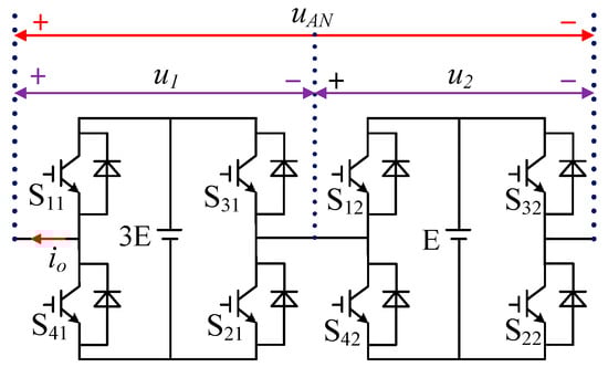
Figure 1.
Topology of Type-III Asymmetric Cascaded H-bridge (ACHB) Inverter.
The Type-III ACHB inverter topology can output more levels than the Type-II topology without adding cascading units. The output of the high-voltage unit is three levels of −3E, 0, and 3E, and the output of the low-voltage unit is three levels of −E, 0, and E. Through the cascade of two units, the inverter can realize phase voltage output of nine levels of −4E, −3E, −2E, −E, 0, E, 2E, 3E, 4E.
Suppose the switching function of unit i (i = 1, 2) is:
Then the output level of each unit can be expressed as:
In the formula, Si represents the switching function of the i-th unit; uHi represents the output level of the i-th unit.
Therefore the total output level of the cascade inverter is:
The state of the cascade inverter and the output level of each unit is represented by (S1, S2). The output level of each unit is as shown in Equation (2), and the total output level of the cascade inverter is as shown in Equation (3). Table 1 shows the operating status of the ACHB inverter. As it can be seen from the synthesis method of PWM levels in each interval in Figure 2, that when different PWM synthesis methods are selected, the output waveforms of different PWM levels will be corresponding, so that the output voltage waveforms of all levels of each cascade units are different. In the following, the positive half cycle is taken as an example to elaborate the synthesis method of the PWM level in each interval.

Table 1.
Inverter output voltage and switching function.
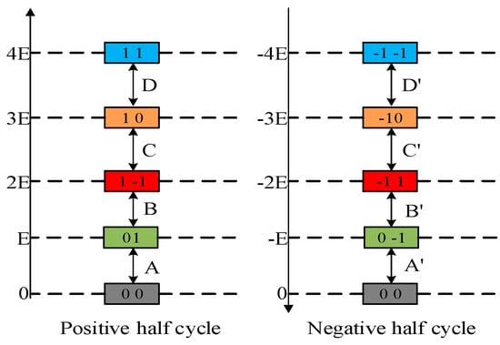
Figure 2.
Synthesis of pulse width modulation (PWM) level in different intervals.
Combined with Table 1 and Figure 2, it can be concluded that: When the inverter outputs 0, ±E, and ±3E, there are redundant switching states. There are 16 switching states in total for the combination of the two units. When the PWM level is synthesized by the hybrid modulation method of A + B + C + D, it can be seen that in the switching states 2E and −2E, the opposite polarity of the output voltage of the high-voltage and low-voltage units must occur, which is determined by the inherent disadvantages of the topology of the Type-III ACHB inverter.
3. Hybrid Frequency Modulation Strategy
The hybrid frequency modulation strategy of Type-III ACHB combines step wave modulation and PWM modulation. The high-voltage unit adopts low frequency step wave modulation, and the switching loss is small; the low-voltage unit adopts high frequency PWM modulation, and the harmonic performance of the output voltage is good.
Figure 3 shows the principle of the HF-PWM modulation strategy. First, a square wave signal va is defined that is obtained by mutually modulating the modulated wave vm of the high-voltage unit and ±1. The drive pulse signal of each switch of the H1 unit can be obtained by using va. Then, by using the modulation wave vm of the high-voltage unit minus va, the modulation signal vref of the low-voltage unit is obtained. Finally, the vref and the triangular carriers vcr1 and vcr1- are modulated, and the driving pulse signals of the respective switching tubes of the low-voltage unit H2 can be obtained.
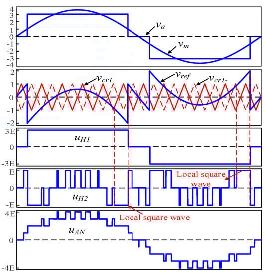
Figure 3.
The principle diagram of hybrid frequency strategy.
The drive logic signals of the high-voltage unit are shown in Equations (4) and (5):
The drive logic signals of the low-voltage unit are shown in Equations (6) and (7):
It can be concluded from Figure 3 that when the traditional HF-PWM strategy is used, an overshoot phenomenon in which the amplitude of the modulation wave vref exceeds the amplitude of the triangular carrier wave occurs in some intervals. This overshoot phenomenon causes a problem of a local square wave in the output voltage, which causes a large increase in the low-frequency harmonics of the output voltage waveform of the Type-III ACHB inverter. Table 2 shows the change of the voltage status of each output phase. The HF-PWM strategy of the Type-III ACHB inverter can only achieve partial PWM modulation. When the phase voltage output is −E~−2E and E~2E, PWM modulation cannot be realized.
Table 2.
Synthesis method of voltage with Hybrid Frequency Pulse Width Modulation (HF-PWM).
4. Modified Hybrid Frequency Modulation Strategy
Against the problems of the above hybrid frequency modulation strategy, a modified hybrid frequency modulation (MHF-PWM) strategy is proposed in this paper. The modulation principle is shown in Figure 4. The high-voltage unit performs sinusoidal pulse width modulation (SPWM) by using a sine wave vm and a pair of positive and negative inversion carriers vcr2 and vcr2−, thereby obtaining driving logic signals of the switching tubes of the high-voltage unit. The low-voltage unit adopts a single-pole frequency-doubled SPWM modulation method, and performs a logic operation on the modulated wave vref and the carriers vcr1 and vcr1 to obtain driving pulse signals of the switching tubes of the low-voltage unit. Among them, the amplitude of carrier vcr1 and vcr1− is E, the frequency is 1/2 of vcr2, and the phase difference is 180°. Since vcr1 and vcr1− have the characteristics of carrier phase shifting, H2 can output high frequency PWM waveforms at a lower switching frequency.
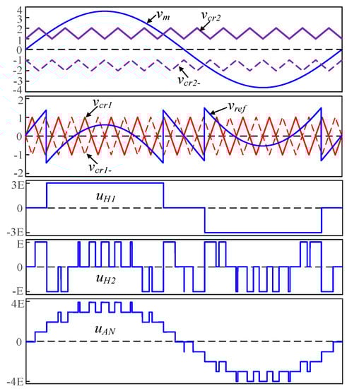
Figure 4.
The principle diagram of modified hybrid frequency modulation (MHF-PWM).
Compared with the HF-PWM strategy, the MHF-PWM strategy reduces the degree of over-modulation of the modulated wave and the triangular carrier, so that the output voltage does not have a local square wave. Therefore, the problem of the HF-PWM strategy in the Type-III ACHB inverter only achieving partial PWM modulation is effectively solved, and the quality of the output voltage waveform of the inverter is improved. And through the logical relationship operation, the equivalent switching frequency of the low-voltage unit is doubled, thereby avoiding the problem of relatively poor output voltage harmonic characteristics due to the low frequency of the high-voltage unit under hybrid frequency modulation.
Assume that the output voltage of the high-voltage unit of the inverter is u1. As can be seen from Figure 4, the fundamental voltage of the output voltage of the inverter is:
where m (0 < m ≤ 1) is the modulation ratio.
The generation of the high-voltage and low-voltage unit drive logic signals is given below. Among them, the modulation wave vref of the low-voltage H2 unit can be expressed as:
The drive logic signals for the high-voltage H1 unit are shown in Equations (10) and (11):
The drive logic signals for the low-voltage H2 unit are shown in Equations (12) and (13):
Table 3 shows the change state of each output voltage under the MHF-PWM strategy. As can be further seen from Table 3, When the phase voltage output of the Type-III ACHB inverter is −E~−2E and E~2E, the low-voltage unit realizes PWM completely, so that there is no local square wave in the output voltage, which effectively improves the quality of the output voltage waveform of the Type-III ACHB multilevel inverter.
Table 3.
The principle of MHF-PWM.
5. Simulation
In order to verify the effect of MHF-PWM strategy in the Type-III ACHB Inverter, the simulation model was built in the Matlab simulation environment for the HF-PWM strategy and the MHF-PWM strategy proposed in this paper, and the simulation was verified. The relevant parameters in the simulation model are shown in Table 4.
Table 4.
Simulation model parameters.
The simulation waveform of output voltage and current under the control of traditional HF-PWM and MHF-PWM is shown in Figure 5. As can be seen from Figure 5a, when the traditional HF-PWM strategy was used, an overshoot phenomenon in which the amplitude of the modulation wave vref exceeded the amplitude of the triangular carrier wave occurred in some intervals. Therefore, it was clearly seen that the output voltage uH2 of the low-voltage unit corresponding to the over-modulated region output was not a PWM wave, but a local square wave. The area corresponding to the output phase voltage uAN of the inverter can only be a square wave waveform; this results in a substantial increase in the low frequency sub-harmonic content in the phase voltage waveform. It can be seen from Figure 5b, that under the MHF-PWM control, there was no area for outputting a square wave waveform in the whole cycle, which solved the problem of the local square wave of the output voltage. Therefore, the low-frequency sub-harmonic content of the phase voltage was much smaller than that of the HF-PWM control and the waveform quality was better. As can be seen in Figure 5a,b, both the low-voltage H2 unit and the high-voltage H1 unit had the phenomenon of opposite polarity of output voltage, so the two modulation strategies had the problem of current backflow, which was determined by the inherent disadvantages of the topology of the Type-III ACHB inverter.
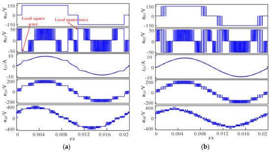
Figure 5.
Simulation voltage waveforms. (a) HF-PWM strategy simulation waveform, (b) MHF-PWM.
The spectrum of output phase voltage, phase current and line voltage of the HF-PWM and MHF-PWM strategies proposed in this paper are shown in Figure 6. It can be seen from Figure 6a,b,e, that under HF-PWM strategy, the harmonic components of phase voltage uAN and phase current iAN were mainly concentrated near 2mf, such as 2mf ± 3, 2mf ± 7, etc., among which the amplitude of the 3rd, 5th, and 7th harmonics was higher. The Total Harmonic Distortion (THD) of uAN was 17.32%, the THD of iAN was 8.16%. Because of the three-phase symmetrical load, the waveform of uAB had no 3th harmonic, but its 5th and 7th harmonic amplitude was still large, the THD of uAB was 13.78%. It can be seen from Figure 6c,d,f, that under the MHF-PWM strategy, the spectrum of the uAN and uAB voltage waveforms was also mainly distributed around 2mf, but the low-frequency sub-harmonics such as the 3rd, 5th, and 7th harmonics were basically eliminated. The THD contents of uAN and uAB were 16.63% and 13.53%, respectively, and the THD of iAN was 2.34%. Therefore, the MHF-PWM strategy proposed in this paper can eliminate the low-frequency sub-harmonics in the output voltage waveform of the Type-III ACHB nine-level inverter, which greatly improves the quality of the inverter output voltage waveform.
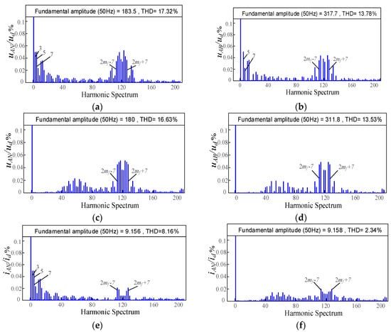
Figure 6.
Spectra of voltage. (a) Spectrum of uAN under HF-PWM strategy. (b) Spectrum of uAB under HF-PWM strategy. (c) Spectrum of uAN under MHF-PWM strategy. (d) Spectrum of uAB under MHF-PWM strategy. (e) Spectrum of uAN under HF-PWM strategy. (f) Spectrum of uAN under HF-PWM strategy.
Figure 7a,b are the corresponding curves of THD and modulation degree m of output phase voltage uAN and output line voltage uAB under three modulation strategies, respectively. When the three control strategies simultaneously output the voltage waveform of the nine-level inverter, the THD value of the output voltage under the HF-PWM strategy and the PS-PWM strategy was almost identical throughout the modulation period, and was higher than the THD value of the output voltage under the MHF-PWM strategy. Therefore, as shown in Figure 7, the MHF-PWM strategy proposed in this paper can eliminate the low-frequency sub-harmonics in the output voltage waveform of the Type-III ACHB nine-level inverter, thereby improving the spectral characteristics of the inverter output voltage waveform and reducing the amplitude of THD.
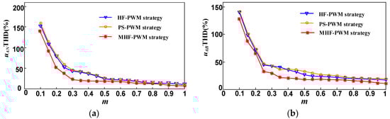
Figure 7.
The corresponding curves of Total Harmonic Distortion (THD) and modulation of uAN and uAB under three modulation strategies. (a) Corresponding curve between the THD value of uAN and the modulation degree. (b) Corresponding curve between the THD value of uAB and the modulation degree.
Figure 8 shows the DC-side current waveform of the low-voltage H2 unit under HF-PWM and MHF-PWM strategy control, respectively. It can be seen that due to the inherent disadvantages of the topology of the Type-III ACHB inverter, inevitably, the phenomenon of high-pressure H1 energy pouring into the low-pressure H2 unit occurred, although both of these modulation strategies had problems in which high-voltage units injected energy into the low-voltage unit and generated current backflow and power backflow. However, it can be clearly seen from the figure that the average current under MHF-PWM control was much larger than that of HF-PWM. This shows that, compared with the HF-PWM strategy control, the high-voltage H1 unit under the MHF-PWM strategy had less energy to inject into the low-voltage H2 unit. Therefore, it can be proved that the MHF-PWM strategy can reduce the degree of current backflow, thereby reducing the imbalance of the output power of the high-voltage H1 unit and the low-voltage H2 unit.
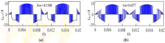
Figure 8.
DC current waveform of a low-voltage unit. (a) HF-PWM modulation. (b) MHF-PWM modulation.
Figure 9 shows the waveforms of the instantaneous power output of each cascade unit under HF-PWM and MHF-PWM strategy control. It can be seen from the figure that in order to obtain the nine-level phase voltage output waveform of the Type-III ACHB inverter, the low-voltage unit needed to bear the energy from many high-voltage units in a specific area. Compared with the average power of the low-voltage unit under the HF-PWM strategy, under the control of MHF-PWM strategy, the energy accumulation of the low-voltage unit was small, which effectively inhibited the energy accumulation of the high-voltage unit to the low-voltage unit, and greatly reduced the degree of current backflow.
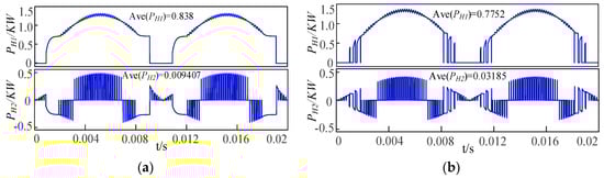
Figure 9.
Instantaneous power output of units at all levels. (a) HF-PWM modulation. (b) MHF-PWM modulation.
Table 5 shows the comparison of different strategies when applied to the Cascaded H-bridge (CHB) nine-level inverter. It can be seen that the MHF-PWM strategy proposed in this paper had the following advantages compared with the HF-PWM strategy and the modulation strategy proposed in literature [20,21,22,23]: The problem of local square wave of output voltage was solved; the accumulation of energy transmitted by the high-voltage H1 unit to the low-voltage H2 unit was effectively suppressed; the degree of current backflow was reduced; the THD value of output line voltage was the lowest, which effectively improved the quality waveform of output line voltage.
Table 5.
Comparison of different strategies.
6. Experiment
In order to further verify the actual control effect of the proposed MHF-PWM control method in this paper, the circuit block diagram of MHF-PWM driving logic signal was established, as shown in Figure 10.
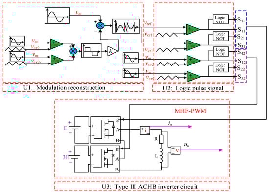
Figure 10.
Driving logic signal generating circuit of MHF-PWM.
The main parameters were as follows: The input voltage of DC side was 75 V and 25 V respectively, output voltage frequency 50 Hz, carrier frequency 5 kHz, filter inductance L = 4 mH, load resistance R = 20 Ω, carrier ratio mf = 100, modulation degree m = 0.85.
Figure 11 shows the experimental results of the ACHB nine-level inverter under the traditional hybrid modulation strategy. Figure 11a shows the output waveforms of the two-unit output voltages uH1 and uH2 and the phase voltage uAN, uH1 is a staircase wave and uH2 is a high-frequency PWM wave. When uAN is in [25V, 50V] and [−50 V, −25V], continuous PWM wave output cannot be achieved due to overshoot problem; Figure 11b,c are harmonic spectrum diagrams of the output phase voltage uAN and the phase current iAN, respectively. It can be seen from the figure that the harmonics of uAN and iAN were mainly 2mf ± 7th harmonics, and a large number of low-frequency harmonics such as 3th, 5th, and 7th, and the THD values of uAN and iAN were 17.59% and 8.23% respectively.
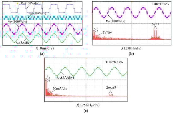
Figure 11.
Experimental waveform of HF-PWM. (a) Output voltage and current waveform. (b) uAN and harmonic spectrum. (c) iAN and harmonic spectrum.
Figure 12 shows the experimental results of the ACHB inverter under the MHF-PWM strategy. Figure 12a shows the output waveforms of the two-unit output voltages uH1 and uH2 and the phase voltage uAN, uH1 and uH2 are high frequency PWM waves. This strategy solved the problem of local square wave when phase voltage uAN was in [25 V, 50 V] and [−50 V, −25 V], and realized the continuous PWM wave output of output voltage. Figure 12b,c are harmonic spectrum diagrams of the output phase voltage uAN and the phase current iAN, respectively. It can be seen from the figure that although the harmonics of uAN and iAN mainly contained the 2mf ± 7th harmonic, however, their 3th, 5th, 7th, and other low frequency harmonics were substantially eliminated. The THD values of uAN and iAN were 16.85% and 2.45%, respectively. Compared with the results of the THD values of uAN and iAN of 17.59% and 8.23% under the HF-PWM strategy, the THD of uAN and iAN under the MHF-PWM strategy was lower than that of the traditional HF-PWM, thus improving the quality of the inverter output voltage waveform.
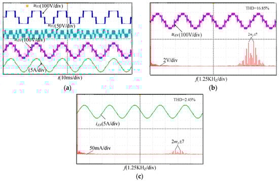
Figure 12.
Experimental waveform of HF-PWM. (a) Output voltage and current waveform. (b) uAN and harmonic spectrum. (c) iAN and harmonic spectrum.
It can be seen from the experimental waveforms that the MHF-PWM strategy proposed in this paper solved the problem of local square waves due to overshoot of the output voltage waveform of the low-voltage unit, and basically realized PWM modulation in the full range, thereby eliminating the 3rd, 5th, and 7th low-frequency harmonics in the output voltage waveform of Type-III ACHB nine-level inverter. The THD values of uAN and iAN were 16.85% and 2.45%, respectively. Compared with the results of the THD values of uAN and iAN of 17.59% and 8.23% under the HF-PWM strategy, the THD of uAN and iAN under the MHF-PWM strategy was lower than that of the traditional HF-PWM, thus improving the quality of the inverter output voltage waveform. And the experimental waveform of MHF-PWM was basically consistent with the simulated waveform, so the validity and authenticity of the modulation strategy was confirmed.
7. Conclusions
When the Type-III ACHB nine-level inverter adopted the traditional HF-PWM modulation strategy, this strategy had some problems such as only partial PWM modulation, large low-order harmonic content of output voltage waveform, and the high-voltage H1 unit pouring energy into the low-voltage H2 unit. In this paper, an MHF-PWM strategy is proposed, and the following conclusions are obtained through simulation and experimental results:
- (1)
- The MHF-PWM strategy solves the problem of local square wave caused by the overshoot of the output voltage waveform of the low-voltage unit by modifying the modulation wave of the low-voltage H2 unit, thereby eliminating the 3rd, 5th, and 7th low-frequency harmonics in the output voltage waveform of the Type-III ACHB nine-level inverter. At the same time, the THD of uAN and iAN under the MHF-PWM strategy is reduced compared to the traditional HF-PWM, which effectively improves the quality of the inverter output voltage waveform. This strategy retains the advantage that the spectrum content is mainly distributed on both sides of 2mf under the traditional HF-PWM strategy.
- (2)
- Compared with HF-PWM strategy control, the high-voltage H1 unit under the MHF-PWM strategy has less energy to inject into the low-voltage H2 unit, which effectively inhibits the accumulation of energy of the high-pressure H1 unit to the low-pressure H2 unit, and reduces the degree of current backflow. Therefore, the unbalanced degree of output power of high-voltage and low-voltage units is also reduced.
- (3)
- Compared with the traditional PS-PWM strategy, the MHF-PWM strategy requires fewer switching devices under the same output voltage and power level. Moreover, the THD value of the output voltage under MHF-PWM modulation is lower than that under PS-PWM control throughout the modulation period, especially when the modulation is 0.2 < m < 0.45.
Author Contributions
Conceptualization, W.R.; methodology, W.R.; validation, W.R., Q.W., G.S. and Z.M.; writing—original draft preparation, W.R.; writing—review and editing, M.Y. All authors have read and agreed to the published version of the manuscript.
Funding
This research was funded by National Natural Science Foundation of China, grant number 51767007; Jiangxi Provincial Industrial Science and Technology Support Project, grant number 20192BBEL50011; Jiangxi Natural Science Foundation Project, grant number 20192BAB206036; Jiangxi Provincial Youth Science Foundation of China, grant number GJJ190312.
Conflicts of Interest
There are no conflicts of interest regarding the publication of this paper.
References
- Azeem, H.; Yellasiri, S.; Jammala, V. A Fuzzy Logic Based Switching Methodology for a Cascaded H-Bridge Multi-Level Inverter. IEEE Trans. Power Electron. 2019, 34, 9360–9364. [Google Scholar] [CrossRef]
- Liang, X.; He, J. Load model for medium voltage cascaded H-Bridge Multi-Level Inverter Drive Systems. IEEE Power Energy Technol. Syst. J. 2016, 3, 12–23. [Google Scholar] [CrossRef]
- Khoucha, F.; Lagoun, S.M.; Marouani, K. Hybrid Cascaded H-Bridge multilevel-inverter Induction-Motor-Drive direct torque control for automotive applications. IEEE Trans. Ind. Electron. 2010, 57, 892–899. [Google Scholar] [CrossRef]
- Saroj, K.; Sahoo, T.B. Phase-Shifted Carrier-Based Synchronized Sinusoidal PWM Techniques for a Cascaded H-Bridge Multilevel Inverter. IEEE Trans. Power Electron. 2018, 33, 513–524. [Google Scholar]
- Jahan, H.K.; Abapour, M.; Zare, K. Switched-capacitor-based single-source cascaded H-bridge multilevel inverter featuring boosting ability. IEEE Trans. Power Electron. 2018, 34, 1113–1124. [Google Scholar] [CrossRef]
- Manjrekar, M.D.; Lipo, T.A. A Hybrid Multilevel Inverter Topology for Drive Applications. Appl. Power Electron. Conf. Expo. 1998, 3, 523–529. [Google Scholar]
- Zhang, Y.G.; Long, L.Z.; Chen, C.L.; Kuang, G.J. Study of leakage current suppression method based on NPC photovoltaic grid-connected inverter. Electr. Mach. Control 2013, 17, 15–21. [Google Scholar]
- Gao, Z.; Lu, Q. A Hybrid Cascaded Multilevel Converter Based on Three-Level Cells for Battery Energy Management Applied in Electric Vehicles. IEEE Trans. Power Electron. 2018, 34, 7326–7349. [Google Scholar] [CrossRef]
- Zeng, X.; Gong, D.; Wei, M. Research on novel hybrid multilevel inverter with cascaded H-bridges at alternating current side for high-voltage direct current transmission. IET Power Electron. 2018, 11, 1914–1925. [Google Scholar] [CrossRef]
- Lai, Y.-S.; Shyu, F.-S. Topology for hybrid multilevel inverter. Electr. Power Appl. IEEE Proc. 2002, 149, 449–458. [Google Scholar] [CrossRef]
- Chattopadhyay, S.K.; Chakraborty, C. Performance of Three-Phase Asymmetric Cascaded Bridge (16:4:1) Multilevel Inverter. IEEE Trans. Ind. Electron. 2015, 62, 5983–5992. [Google Scholar] [CrossRef]
- Jamuna, P.; Rajan, C.C.A.; Gowri, K.; Vijayasanthi, V. Analysis of new H-bridge based cascaded multilevel inverter. In Proceedings of the 2016 10th International Conference on Intelligent Systems and Control (ISCO), Coimbatore, India, 7–8 January 2016. [Google Scholar]
- Sharifzadeh, M.; Vahedi, H.; Portillo, R. Selective harmonic mitigation based self-elimination of triplen harmonics for single-phase five-level inverters. IEEE Trans. Power Electron. 2018, 34, 86–96. [Google Scholar] [CrossRef]
- Marquez, A.; Leon, J.I.; Vazquez, S. Variable-angle phase-shifted PWM for multilevel three-cell cascaded H-bridge converters. IEEE Trans. Ind. Electron. 2017, 64, 3619–3628. [Google Scholar] [CrossRef]
- Quan, Z.; Li, Y.W. Phase-Disposition PWM Based 2DoF-Interleaving Scheme for Minimizing High Frequency ZSCC in Modular Parallel Three-Level Converters. IEEE Trans. Power Electron. 2019, 34, 10590–10599. [Google Scholar] [CrossRef]
- Ye, M.; Ren, W.; Chen, L.; Wei, Q.; Song, G.; Li, S. Research on Power-Balance Control Strategy of CHB Multilevel Inverter Based on TPWM. IEEE Access 2019, 7, 157226–157240. [Google Scholar] [CrossRef]
- Bu, F.; Pu, T.; Huang, W.; Zhu, L. Performance and Evaluation of Five-Phase Dual Random SVPWM Strategy with Optimized Probability Density Function. IEEE Trans. Ind. Electron. 2019, 66, 3323–3332. [Google Scholar] [CrossRef]
- Manjrekar, M.; Steimer, P.; Lipo, T. Hybrid multilevel power conversion system: A competitive solution for high-power applications. IEEE Trans. Ind. Appl. 2000, 36, 834–841. [Google Scholar] [CrossRef]
- Ye, M.; Kang, L.; Xiao, Y.; Song, P.; Li, S. Modified hybrid modulation strategy with power balance control for H-bridge hybrid cascaded seven-level inverter. IET Power Electron. 2018, 11, 1046–1054. [Google Scholar] [CrossRef]
- Abraham, B.T.; Benny, A. Asymmetric multilevel hybrid inverter with reduced number of switches. In Proceedings of the 2014 Annual International Conference on Emerging Research Areas: Magnetics, Machines and Drives (AICERA/iCMMD), Kottayam, India, 24–26 July 2014. [Google Scholar]
- Sun, X.; Yun, Z. Hybrid Control Strategy for a Novel Asymmetrical Multilevel Inverter. In Proceedings of the 2010 International Conference on Intelligent System Design and Engineering Application, Changsha, China, 13–14 October 2010. [Google Scholar]
- Chen, Z.; Wang, Z.; Liu, Y. A unipolar PWM strategy for hybrid cascaded multilevel converters. In Proceedings of the IECON 2014-40th Annual Conference of the IEEE Industrial Electronics Society, Dallas, TX, USA, 29 October–1 November 2014; pp. 1154–1160. [Google Scholar]
- Ren, L.; Gong, C.; He, K.; Zhao, Y. Modified hybrid modulation scheme with even switch thermal distribution for H-bridge hybrid cascaded inverters. IET Power Electron. 2017, 10, 261–268. [Google Scholar] [CrossRef]
© 2020 by the authors. Licensee MDPI, Basel, Switzerland. This article is an open access article distributed under the terms and conditions of the Creative Commons Attribution (CC BY) license (http://creativecommons.org/licenses/by/4.0/).