Abstract
Radio Frequency Identification (RFID) is gaining significant thrust in many application fields such as identification and real-time localization systems. Consequently, nowadays, the demand for integrated RFID-Sensors networks is increasing. Usually, numerous RFID-Sensors are deployed to form such types of networks. Then, an RFID tag can be located in the reading field of more than one reader that generates duplicated data reception at the base station. The data redundancy transmission causes unnecessary energy consumption and network overloading that contributes to the augmentation of transmission delays. In this paper, we tackle the data duplication reception problem. We propose an efficient and proactive filtering scheme for redundant data based on a preliminary broadcast. Our scheme allows us to prevent and significantly reduce the redundant data and improve the performances of the integrated RFID-sensor network.
1. Introduction
Today, we attest to the great emergence of Wireless Sensor Networks (WSNs). These networks are self-organizing and consist in general of a large amount of autonomous sensor nodes, with low resources, that transmit sensed data to the base stations [1,2]. However, these sensor networks are facing enormous challenges and issues that concern energy consumption and delays due to network congestion [3]. New solutions are emerging to considerably reduce the impact of energy issues. Recently, these techniques have consisted of combining the sensor networks with other technologies to prolong a network’s lifetime [4,5]. Also, many applications for WSNs tend to use the Radio Frequency Identification (RFID) technology [6]. This solution is revolutionizing the WSNs because of its low energy consumption and ability to identify and exchange data. Recently, some researches and applications have focused on taking advantage of RFID technology to build energy-efficient WSNs [7].
Integrated Sensor-RFID networks are usually targeted for industrial applications (they can be used, for example, in production line management) [8]. In these networks, tags should be writable, active and integrated with special sensors to meet the needs of feedback status (temperature, pressure, humidity, etc.) of the tagged object. In our work, we focus on one architecture type for RFID-sensor networks: The Tag as sensor [9]. In this architecture, the Sensor concept is extended to consider the RFID transponder/tag devices as a sensor. The sensor-tag is supposed to be semi-active. It goes into the wake-up mode only when it starts the task of sensing data. The tag automatically attaches a tag to the message and stores it in its flash memory. The reader latter collects the combined - and sends it wirelessly towards the sink. However, in most of the RFID-WSN networks, the readers-tags are deployed randomly. This can easily generate a situation where many tags are in the reading range of several readers. This situation causes collisions during reading [10] and the transmission of duplicated data [11]. These two main problems may cause a high level of network congestion that increases delays and decreases packet delivery ratio (PDR). Figure 1 shows an example of a deployed RFID sensor network that includes RFID sensor tags and readers. In this figure, for example, tag data are read by readers and . Without data filtering, the data will be received twice in the server computer.
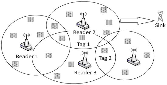
Figure 1.
RFID Sensor Network.
In this paper, we consider the problem of data redundancy. We propose a proactive scheme in order to avoid the transmission of duplicated data through the network. The remainder of this paper is organized as follows. In the next Section, we give some background about RFID technology. Section 3 presents a survey on the existing methods that deal with redundant data filtering. Section 4 gives the problem formulation of redundant reader’s data. In Section 5, we propose a solution based on a proactive scheme in order to reduce redundancy. Then, in Section 6, we present the implementation of our algorithm under NS-2 simulator and discuss the results. Finally, Section 7 concludes the paper and presents some perspectives.
2. Background
An RFID system is generally based on tags and readers. This type of system was developed to be used in applications where it is necessary to obtain identity and data of targeted objects through RF signals. In an RFID system, the number of tags is larger than the number of readers. The reader transmits a signal to one or more radio tags located into its reading field, and the tag transmits back an . A dialogue is then set according to a predefined communication protocol, and data are exchanged. In addition to the wireless data transfer, the communication via the antenna also allows transfers without sight between the reader and the tag through substances or opaque material to light. RFID tags are provided in the form of labels that can be attached to or incorporated in products or as microscopic capsules which can be implanted in living organisms, e.g, animals and humans bodies.
Most RFID tags operate passively without battery, pending the radio frequencies sent by transceivers and using the energy of the received radio signal to answer. The radio signal is transmitted within a radius from a few centimeters to a few meters, depending on the power and the used frequency. For low frequencies: 100–500 kHz, a reading distance of a few centimeters. For Medium frequency: 10–15 MHz, there is a reading distance of 50–80 cm. For high frequencies of 850–950 MHz to 2.4–5.8 GHz, there is a reading distance of one to several meters. There are three types of RFID tags: Passive, active and semi-active.
Passive tags are the most economical RFID tags and more generally used in most of applications. These tags are not equipped with internal batteries, and expect energy from readers. The RFID readers send electromagnetic waves to the antenna of the tag to wake up and send a signal to the reader using the energy of the waves.
Active tags use their own energy to emit the waves. This energy is stored in an internal battery. Thus, they may have a very long distance reading. They are more expensive than passive tags and are therefore generally used to track valuable items.
Semi-active tags are intermediate between active tags and passive ones. They typically use a battery as a power source, but can also transmit data using the energy generated by waves of RFID readers. Usually, semi-active tags are used in RFID sensor networks. One of most common semi-active sensor tags used for RFID sensor network is the the Wireless identification sensor platform (WISP) [12].
In this work, we consider readers as nodes in a wireless semi-active tag-sensor network, where readers are equipped by RF transceivers to perform communications using IEEE 802.15.4/Zigbee standard. This standard is useful for RFID-sensor networks because of its low cost and low power consumption [13].
3. Related Work
Redundant data problem in an RFID sensor network has gained more and more interest in the last few years. Several methods have been proposed to optimize the transmission mechanisms in RFID networks in order to reduce redundant data and improve network’s overhead and energy consumption. Let us first present some previous works that treat coverage issues and data duplication elimination in typical wireless sensor networks. The data aggregation is a solution proposed to reduce data transmission and energy consumption in WSNs, since the major source of energy consumption is radio communication [14]. The data aggregation remains one of the most developed solutions to optimize the communication overhead. Its concept is simple: instead of sending data in the network toward the sink, the network ensures that only useful data are sent. Many researches presented data aggregation algorithms for WSNs that go from simple average computing to algorithms taking into consideration the security of the networks. However, it is very important to keep a balance between communication costs and data aggregation in order to reduce energy consumption as proposed in [15]. Their approach proposes an automated strategy for data filtering that attempts to strike a balance between computation and communication energy consumption.
Concerning RFID sensor networks, authors in [5] studied the coverage problem where each tag has to be in the reading area of at least one reader. The authors presented an analytic formulation for the problem by defining a related problem called point provisioning that consists of minimizing the number of readers while maintaining an optimal coverage of the network. The approach is interesting and tries to optimize the deployment of readers over an RFID network area. However, the absence of an exact solution for the presented problem makes the solution just an approximation. Also, this solution does not take into consideration the path loss or attenuation of the reader’s signal.
The coverage and data redundancy issues were first gathered in only one problem in [16], where the authors present the problem of redundant data in an RFID network and proved that this problem is NP-hard. In their work, they also proposed a solution for data redundancy that detects redundant readers, turning them off. The method is very simplistic, and may not be applied in real applications where readers are carrying sensors and cannot be turned off.
In [17], authors proposed an improvement of first adaptive cleaning methods for RFID data filtering called SMURF. Their method models the unreliability of RFID readings by viewing RFID streams as a statistical sample of tags and then exploits techniques in sampling theory to drive its cleaning processes. This method filters a considerable amount of data and also removes many other anomalies such as noise. However, this solution is proposed in order to run using a middle-ware at the base station, and it is very difficult to implement it into the network because of limited energy of reader nodes.
In [18], the authors proposed the concept on In-network data filtering for RFID networks. Their method called In-Network Parent Filtering Mechanism (INPFM), consists of filtering data gradually on its route to the sink. They also proposed a phased filtering mechanism that filters data while routed to sink according to a tree topology. Their approach consists of filtering data at every hop from a child to a parent. This method showed good results in terms of the network’s overhead but only in small-size RFID sensor networks. However, such a method for large scale networks will generate high computational costs.
Later, Kashif et al. [19] proposed an improvement for the In-network data filtering proposed by [18]. In fact, they first proposed a topology for the RFID-sensors network based on clusters without specifying if the clustering algorithm takes into consideration the deployment of tags. In this work, we are interested in the proposed filtering scheme called Energy Efficient In-network RFID Data Filtering Scheme (EEIN). In this scheme, the authors defined two types of redundancy for data; the “intra-cluster” and the “inter-cluster”. The solution proposed for the intra-cluster problem consists of filtering data at the cluster-head. In fact, if two or more data packets come from the same sensor-tag, data are filtered and the cluster sends only one data per tag toward the base station. The solution proposed for inter-cluster is a little complex. In fact this redundancy happens when there are tags located in two or more clusters of the network, and this may cause unnecessary routed data through the network, which results in important delays and additive energy consumption for the reader nodes. The solution proposes to include a feedback message, including the of each tag, sent to all cluster heads. Then, when a cluster head receives data from inter-cluster nodes, it checks its tag list. If there is any feedback coming from the same tag, the coordinator of the network modifies the route of these tags. In [20], the authors improved the previous scheme to take into consideration the network’s delay. They called this new method: In-network RFID Duplicate Data Filtering (IRDF). However, these two methods do not include a data aggregation algorithm while the main goal was the minimization of the number of packets sent over the network. Also, their method can only be applied if the network is in cluster topology, and it does not take the routing into consideration.
Finally, in 2016, the authors of [21] proposed an approach for filtering RFID duplicated data from RFID data based on a modified Bloom Filter that uses only a single hash function. The proposed approach is interesting but considers only passive tags and is not comparable with our approach to the RFID sensor system.
In summary, the methods we have presented above are based on algorithms that filter data while being sent into the network. Filtering all this data obviously has a negative impact on the computational cost, at nodes, the energy consumption, and the network overhead. None of the previous work in the literature has proposed to develop an algorithm that can filter such data at the nodes before being sent in the network. That is the motivation of our current work, where we present a proactive solution that permits us to detect duplication and delete it at the reader nodes. The next section present the problem formulation and gives details of our solution.
4. Presentation of Problem
In a dense network, it happens that some tags are located into the reading area of two or more readers (as depicted in Figure 1). This situation causes redundant data that may be sent in the network and causes network congestion, delays, decreases the packet delivery ratio, and finally decreases network’s lifetime. The packets containing duplicated data and traveling over the network can be divided into two categories:
Intra-path redundant data: is the situation when the tag that generates redundancy is located between two readers in the same path as shown in Figure 2a. It can be easily detected, and the data can be filtered in the next hop.
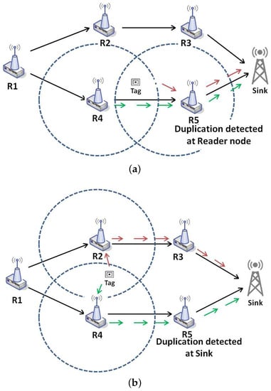
Figure 2.
Data Duplication Problem (a) intra-path data duplication between Reader 4 and Reader 5; (b) extra-path data duplication between Reader 2 and Reader 4.
Extra-path redundant data: is the situation when the tag is located on the reading range of two readers that in topology belongs to two different routes as shown in Figure 2b.
In this paper, the main effort is focused on resolving the problem of data duplication and the sensor tag mobility is not considered. We propose a hybrid solution to reduce both intra or extra path duplication. This solution is based on a discovery phase where extra-path redundancy is detected before readers start sending data. We call our solution: Proactive Data Filtering Scheme (PDFS). Our proposed solution leads to avoiding the transmission of this kind of redundant data in the network. Next, we present the details of our solution.
5. Proactive Data-Filtering Scheme
We first assume that the used tags are semi-active. They are equipped with small batteries that provide energy only for local tasks, especially for the sensor. The energy provided by batteries is not used to perform communications with other readers. We also assume the use of a mesh topology as in [22]. In this topology all nodes (readers) carry enough energy and memory to process data and act as routers to relay data packets to the other nodes. At the moment of reading and during transmission to the sink, the sensor-tags are considered to be passive and are not considered as part of the network. Our approach for a proactive data filtering is based on three principal phases called: Preliminary phase (PP) Network Discovery phase (NDP) and Network Reading phase (NRP).
5.1. Network Discovery Phase (NDP)
Before starts, the network has to decide which nodes will be considered as end-nodes. Those end-nodes are readers located at the extremities of the network. They will have the task to start the by broadcasting a message to all reader nodes. In order to select the readers to be considered as end-nodes, the sink broadcasts a message called Preliminary Message (PM). The goal is to identify the nodes with maximum number of hops. This message includes two main information sources: A sequence number field and a number of hops field. Each node that receives the checks its sequence number to verify if the message has already crossed the node, increments the number of hops, and broadcasts it. After a timeout, corresponding to the entire network propogation delay, each node decides to be an end-node if it has the maximum hops number to reach the sink than. Figure 3 shows an illustrative example where readers 2 and 10 are decided to be end-nodes.
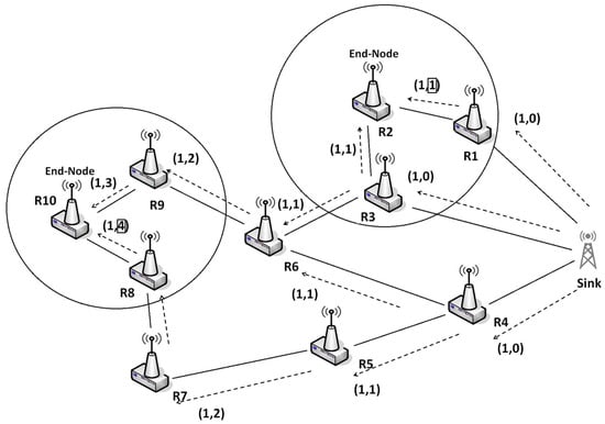
Figure 3.
Preliminary message broadcast over the network.
Thereafter, each end-node initiates a message called Discovery Message (DM) that broadcasts to neighbor readers. has the structure given in Figure 4. It is composed of a sequence of tag lists associated with reader-sources. The first sent by an end-node contains the list of the of tags located in its reading range. We present below the operations performed during NDP by the readers and the sink independently.
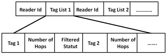
Figure 4.
Discovery Message Structure.
5.1.1. NDP in Reader Nodes
Each reader has a tag list containing the tags located in it reading range. This list is created and updated based on the received from tags.
Once a node receives a Discovery Message (DM) from it neighbor, it first checks if there is an intra-path data duplication by comparing the tag on the received DM with tag from . If similarity is detected, the reader filters the duplicated data, adds its list of tag to the discovery message, and sends it to the next reader. The steps involved in this algorithm are further illustrated in the pseudo-code at Figure 5.
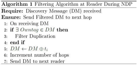
Figure 5.
Filtering Algorithm 1.
Figure 6 illustrates this mechanism. We consider a network composed of four readers. Tags 1–4 are in the reading area of readers 1 and 2. However, tag 3 is in the reading range of both readers, which will generate duplicated data. The first DM is sent by reader 1 toward the sink. The duplication (intra-path) of tag 3 will then be detected and deleted at reader 2.
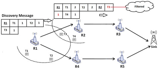
Figure 6.
Discovery Phase sample during Network Discovery Phase: Duplication of tag 3 detected at reader 2.
5.1.2. NDP in the Sink
The sink waits to receive all Discovery Messages. The tag from these messages are stored in a table called sink list S. When receiving all DMs, the sink checks if there is any duplication of tag . If similarity is detected, that means that the same tag arrived from different routes (extra-path duplication), since intra-path duplications are detected and deleted in-network. The Algorithm 2 in Figure 7 eliminates all duplicated tag from the list S. The elimination process is simple; let us suppose that a tag is duplicated and arrived from two readers, the algorithm has to eliminate associated reader with the maximum number of hops. In other words, the algorithm keeps in the list S the Tag- coming from the nearest reader.
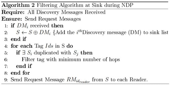
Figure 7.
Filtering Algorithm 2.
Once extra-path duplication of all tags is filtered, the sink decides to request data from readers by sending a Request Messages. These messages will be based on the remained tag (associated to readers) in the sink list S after filtering. Thus, the sink sends a Request Message, whose structure is shown in Figure 8 to all readers. The payload of the Request Message includes a sequence of tag requested by the sink from readers. Each reader will only send data requested by the sink and will locally drop the rest.
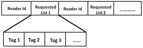
Figure 8.
Request Message Structure.
To summarize the mechanism of NDP, Figure 9 represents the main steps involved in this phase. (i) R1 sends a discovery message to the sink through all routes. All readers filter and aggregate data once the discovery message is received; (ii) The sink receives all discovery messages and decides what tag have to be sent by each reader, to which it sends a request message.
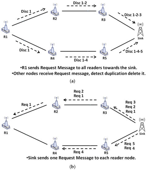
Figure 9.
Example of Network Discovery Phase: (a) discovery messages; (b) request messages.
5.2. Reading Phase (RP)
After the Network Discovery phase is completed, the network starts running. During this phase, called the Reading Phase (RP), readers collect data from sensor-tags and send it through the network. The readers also perform the task of routing data and filtering duplication. When a reader node receives data from another reader, it checks if intra-path data redundancy will be generated. To do that, it activates the reading mechanism to recover new data from the tags. Since all tags are passive during the reading, the reader will receive data from all tags located in its reading range. However, it has to locally delete the extra-path redundant data, and only keep in it the data table data coming from tags requested by the sink in the Request Message. Once done, the reader checks the tag in the received data and compares it with based on the last reading. If duplication is detected, the node removes the data attached to the tag from the message and send it toward the sink. To summarize, the mechanism of filtering during reading phase includes three main steps:
- The reader node receives data, and checks for intra-path duplication to delete it.
- It reads data from tags and only keeps data requested by the sink.
- Finally, the reader adds local data to Data Message and sends it to the sink.
The algorithm for Reading Phase at the readers is also illustrated in the pseudo-code at Figure 10.
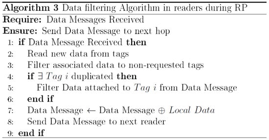
Figure 10.
Filtering Algorithm 3.
6. Simulations and Results
In this section, we evaluate the performances of the RFID system presented in the previous section. The main goal of this work was to develop a proactive data filtering scheme in order to reduce the transmission of redundant data over the network. We compare our scheme with two other methods presented in the related work; IRFD [20], a filtering based on Clustering topology (at cluster head node), and INPFM [18], filtering based on tree topology (at parent node). INPFM is the first method of filtering redundant data into the network, while IRFD is a relatively new method. Since it was difficult to deploy real large-scale network in lab-conditions (150 to 40 sensor tags), only simulations were performed using the Network Simulator 2 (NS2) to study the performances networks.
6.1. Simulation Parameters
In our simulations, we deploy randomly over a 200 × 200 (m) geographical region an RFID-sensor that includes sensor tags and RFID readers. Tags are considered semi passives, and their energy is only used to perform the task of sensing and not for sending data wirelessly. Only the RFID readers form the network. The simulation parameters are presented in Table 1.

Table 1.
Simulation parameters.
We conducted many simulations in order to evaluate the performances of our system. The given results are therefore the average values for 20 different simulations. We evaluate our filtering mechanism in two network conditions: High duplication rate where the amount of tags located in the reading range of two or more readers can reach , and low duplication rate where the amount of tags located in the reading range of two or more readers is up to 10%. As we will see in next results, when duplication increases, the performance of our proactive scheme are more obvious. Since tags are semi-active, each node uses its battery energy for sensing, and storing data in its flash memory. These data will be recovered later by one or many readers. We do not consider the energy problem in this paper. The readers are supposed to carry enough energy to perform the reading and transmission tasks. Also, small batteries carried by the sensor tags are charged enough to provide energy for the sensing tasks.
In order to evaluate the performances and the efficiency of our filtering scheme, we use the following quantitative measurements:
- Amount of sent packets that evaluates the total number of transmissions in the network during all network lifetime.
- Amount of in-network filtered data that represents in theory only the intra-path filtered duplication.
- Average network delay is the first performance result that represents the average end-to-end delay transmission.
- Average Packet Delivery Ratio is the second performance result. We present for this metric, the average Packet loss ratio.
- Average overhead is the last result that shows performances of our scheme. It represents the ratio between the total number of generated packets and the number of received data packets at the sink.
6.2. Main Results
Our first result concerns the number of transmitted packets during both phases of network’s lifetime. In Figure 11a,b, we compared the results of this metric for our proposed scheme with INPFM and IRFD methods. We also present results when the network runs without any filtering scheme. The Sub-Figure 11a shows the number of transmitted packets to the sink versus the number of tags when the duplication ratio is around 40%. We can see how the climbing cadence of generated data sent in the network decreases when our proposed filtering scheme is used. The Sub-Figure 11b also shows the number transmitted packets to the sink versus the number of tags when the duplication ratio is low and around 10%. We can deduce from these figures that when the duplication ratio increases, the performances of our scheme becomes more obvious.
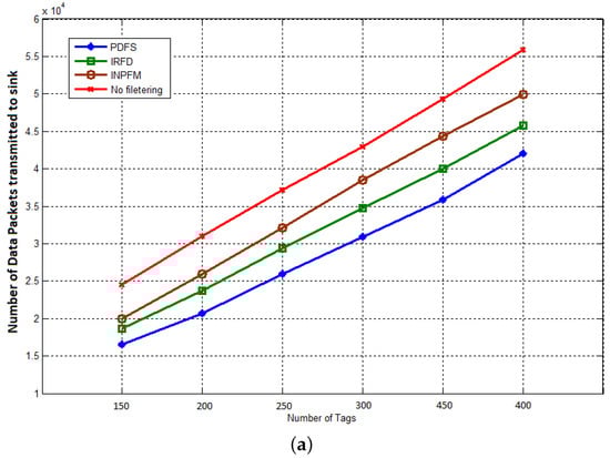
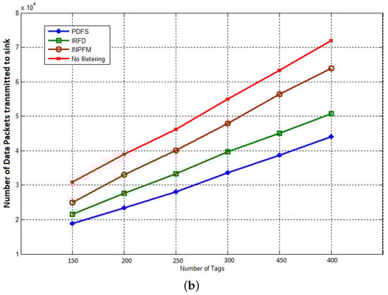
Figure 11.
Transmitted packets to the sink: (a) duplication ratio ; (b) duplication ratio .
We also conducted simulations to compute the amount of filtered data after being sent into the the network. As explained before, our method classifies the duplication problem into two sub-problems: intra and extra path duplication. We explained in the previous section how in our scheme, packets that generate an extra-path situation are removed by readers before being sent into the network. That explains our results where we see that our method filters less data packets than other methods. Figure 12 shows a comparison between IRFD, INPFM and PDFS concerning the number of data messages that have been filtered in the network versus number of tags when duplication ratio is 40% (high duplication ratio) and 10% (low duplication ratio).
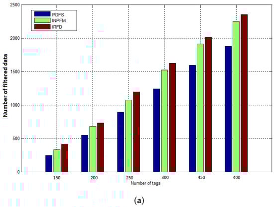
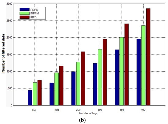
Figure 12.
Amount of data filtered after being sent in the network: (a) duplication ratio ; (b) duplication ratio .
The results given in Figure 13, show how network’s delay is reduced with our filtering scheme. This result can be explained for two reasons: Our scheme considerably reduced the number of transmitted data by eliminating it before being sent into the network, so the network’s congestion is obviously decreased. The second reason is that we reduced the amount of filtered data in the network, and so clearly reduced the time of computation and filtering at the reader nodes.
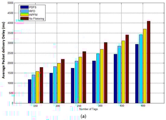
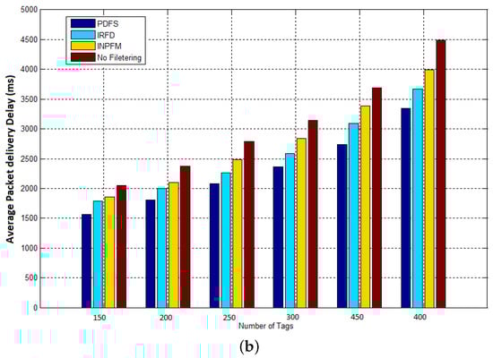
Figure 13.
Average packet delivery delay: (a) duplication ratio ; (b) duplication ratio .
The next result concerns the packet delivery ratio. We present the average Packet loss ratio for this metric. By reducing the number of transmissions, the transmission delays, and the computational time, the performances of the network with our proposed scheme are improved. These previous results have a positive impact on network robustness as shown in Figure 14a,b, that represent respectively the ratio of packets dropped during transmission to sink when the duplication rate is respectively and . It can be deduced from these figures that our scheme considerably reduced the packet loss ratio, and so improved the packet delivery. This is due to the fact that our filtering scheme significantly reduces the number of transmitted data and the average delay into the network.
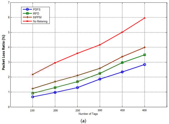
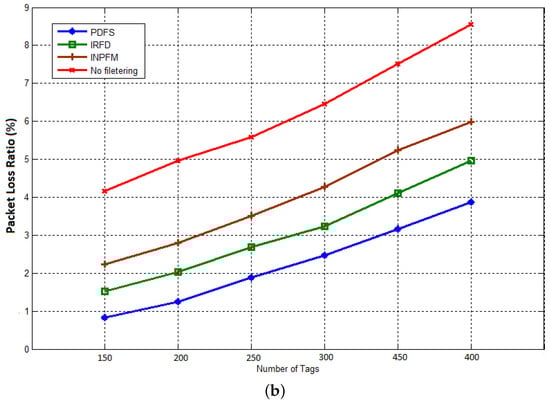
Figure 14.
Packet loss ratio: (a) duplication rate ; (b) duplication rate .
The final result concerns the network overhead. We consider this metric as a ratio between the total number of generated packets and the number of received data packets at the sink. Figure 15a,b show the average network overhead during reading phase for duplication rates 10% and 40%. During this phase, all nodes (readers) send collected data from tags to the sink. We can see how our filtering scheme significantly reduces the network overhead compared with the other methods. We can also notice that, contrary to the previous results, INPFM outperforms IRFD in terms of overhead due to the great number of control packets transmitted in IRFD, especially to detect inter-cluster duplication.
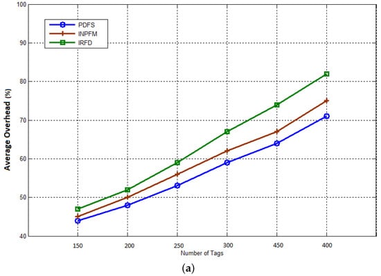
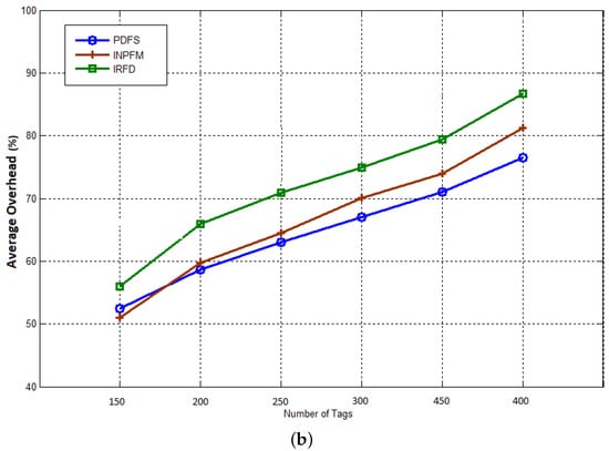
Figure 15.
Average network overhead during Reading Phase: (a) duplication rate ; (b) duplication rate .
7. Conclusions and Future Work
Wireless sensor networks integrated with RFID systems provide an excellent infrastructure for data acquisition, and present a lot of advantages in terms of network’s lifetime and energy consumption. In this paper, we have dealt with one of the key challenges of these networks; the problem of data duplication due to multiple-readings in an area of random tag deployment. We proposed in this work an efficient proactive data elimination scheme that improved significantly the performances of the RFID sensor network, and reduced the computational cost by decreasing the amount of filtered data during transmissions phase. Our scheme proposes a Network Discovery phase at the beginning of network’s lifetime where redundancy is detected and removed before being sent through the network. We compared our scheme with some existing methods in the literature such as IRFD and INPFM, and showed satisfactory results in terms of the network’s performances.
As perspectives for this work, we are implementing our filtering scheme in a medium-scale physical RFID Sensor Network offered by Wireless Identification Sensor Platform (WISP) in order to test its performances in real conditions. Future work will take into consideration the problem of energy and try to propose a balance for the filtering scheme to take into consideration the computational cost and the energy constraint for readers and sensor tags.
Author Contributions
Mourad Ouadou develloped the proposed idea, implemented it, and obtained the results. Ouadoudi Zytoune proposed the scheme, and validated the results
Conflicts of Interest
The authors declare no conflict of interest.
References
- Rawat, P.; Singh, K.D.; Chaouchi, H.; Bonnin, J.M. Wireless sensor networks: A survey on recent developments and potential synergies. J. Supercomput. 2014, 68, 1–48. [Google Scholar] [CrossRef]
- Akyildiz, I.F.; Su, W.; Sankarasubramaniam, Y.; Cayirci, E. Wireless sensor networks: A survey. Comput. Netw. 2002, 38, 393–422. [Google Scholar] [CrossRef]
- Kafi, M.A.; Djenouri, D.; Ben-Othman, J.; Badache, N. Congestion control protocols in wireless sensor networks: A survey. IEEE Commun. Surv. Tutor. 2014, 16, 1369–1390. [Google Scholar] [CrossRef]
- Zhang, D.; Chen, Z.; Zhou, H.; Chen, L.; Shen, X.S. Energy-balanced cooperative transmission based on relay selection and power control in energy harvesting wireless sensor network. Comput. Netw. 2016, 104, 189–197. [Google Scholar] [CrossRef]
- He, S.; Chen, J.; Jiang, F.; Yau, D.K.; Xing, G.; Sun, Y. Energy provisioning in wireless rechargeable sensor networks. IEEE Trans. Mob. Comput. 2013, 12, 1931–1942. [Google Scholar] [CrossRef]
- Srinivasan, S.; Ranganathan, H. RFID sensor network-based automation system for monitoring and tracking of sandalwood trees. Int. J. Comput. Sci. Eng. 2013, 8, 154–161. [Google Scholar] [CrossRef]
- Farris, I.; Militano, L.; Iera, A.; Molinaro, A.; Spinella, S.C. Tag-based cooperative data gathering and energy recharging in wide area RFID sensor networks. Ad Hoc Netw. 2016, 36, 214–228. [Google Scholar] [CrossRef]
- Wang, L.; Da Xu, L.; Bi, Z.; Xu, Y. Data cleaning for RFID and WSN integration. IEEE Trans. Ind. Inform. 2014, 10, 408–418. [Google Scholar] [CrossRef]
- Yang, H.; Yang, S.H. RFID sensor network network architectures to integrate RFID, sensor and WSN. Meas. Control 2007, 40, 56–59. [Google Scholar] [CrossRef]
- Amadou, I.; Mitton, N. High Adaptive MAC Protocol for Dense RFID reader-to-reader Networks. In Proceedings of the International Conference on Ad Hoc Networks, San Remo, Italy, 1–2 September 2015; Springer: Cham, Switzerland; pp. 82–93. [Google Scholar]
- Zhang, S.; McCullagh, P.; Zhou, H.; Wen, Z.; Xu, Z. RFID network deployment approaches for indoor localisation. In Proceedings of the 2015 IEEE 12th International Conference on Wearable and Implantable Body Sensor Networks (BSN), Cambridge, MA, USA, 9–12 June 2015; pp. 1–6. [Google Scholar]
- Sample, A.P.; Yeager, D.J.; Powledge, P.S.; Mamishev, A.V.; Smith, J.R. Design of an RFID-based battery-free programmable sensing platform. IEEE Trans. Instrum. Meas. 2008, 57, 2608–2615. [Google Scholar] [CrossRef]
- Bougard, B.; Catthoor, F.; Daly, D.C.; Chandrakasan, A.; Dehaene, W. Energy efficiency of the IEEE 802.15. 4 standard in dense wireless microsensor networks: Modeling and improvement perspectives. In Proceedings of the conference on Design, Automation and Test in Europe, Munich, Germany, 7–11 March 2005; Volume 1, pp. 196–201. [Google Scholar]
- Rault, T.; Bouabdallah, A.; Challal, Y. Energy efficiency in wireless sensor networks: A top-down survey. Comput. Netw. 2014, 67, 104–122. [Google Scholar] [CrossRef]
- Chao, C.M.; Hsiao, T.Y. Design of structure-free and energy-balanced data aggregation in wireless sensor networks. J. Netw. Comput. Appl. 2014, 37, 229–239. [Google Scholar] [CrossRef]
- Hsu, C.H.; Chen, Y.M.; Yang, C.T. A layered optimization approach for redundant reader elimination in wireless rfid networks. In Proceedings of the 2nd IEEE Asia-Pacific Service Computing Conference, Tsukuba, Japan, 11–14 December 2007; pp. 138–145. [Google Scholar]
- Jeffery, S.R.; Garofalakis, M.; Franklin, M.J. Adaptive cleaning for RFID data streams. In Proceedings of the 32nd International Conference on Very Large Data Bases (VLDB Endowment), Seoul, Korea, 12–15 September 2006; pp. 163–174. [Google Scholar]
- Choi, W.; Park, M.S. In-network phased filtering mechanism for a large-scale RFID inventory application. In Proceedings of the 4th International Conference on IT & Applications (ICITA), Harbin, China, January 2007; pp. 401–405. [Google Scholar]
- Bashir, A.K.; Lim, S.J.; Hussain, C.S.; Park, M.S. Energy efficient in-network RFID data filtering scheme in wireless sensor networks. Sensors 2011, 11, 7004–7021. [Google Scholar] [CrossRef] [PubMed]
- Bashir, A.K.; Park, M.S.; Lee, S.I.; Park, J.; Lee, W.; Shah, S.C. In-network RFID data filtering scheme in RFID-WSN for RFID applications. In Proceedings of the International Conference on Intelligent Robotics and Applications, Busan, South Korea, 25–28 September 2013; Springer: Busan, South Korea; pp. 454–465. [Google Scholar]
- Kamaludin, H.; Mahdin, H.; Abawajy, J.H. Filtering redundant data from RFID data streams. J. Sens. 2015, 2016. [Google Scholar] [CrossRef]
- Kashyap, A.; Lee, K.; Kalantari, M.; Khuller, S.; Shayman, M. Integrated topology control and routing in wireless optical mesh networks. Comput. Netw. 2007, 51, 4237–4251. [Google Scholar] [CrossRef]
© 2017 by the authors. Licensee MDPI, Basel, Switzerland. This article is an open access article distributed under the terms and conditions of the Creative Commons Attribution (CC BY) license (http://creativecommons.org/licenses/by/4.0/).