Abstract
To further satisfy the extreme operating conditions of electric tractors, a pole-changing double-sided excitation permanent magnet vernier motor (PC-DPMVM) is proposed evolving from the existing PC-SPMVM in this paper. Half of the rotor PMs are transferred to the stator small slots, while a consequent-pole rotor structure and stator PM structure can be obtained. Firstly, the simulation and experiments of the existing PC-SPMVM are introduced, which shows the deficiency of the maximum torque output. Then, the evolution process of the proposed PC-DPMVM is illustrated. The rotor modulation and stator modulation behaviors of the PC-DPMVM are introduced based on airgap field modulation theory. The main working PM flux density harmonics are deduced further. Next, electromagnetic performance comparisons are made between two PC-PMVMs by using finite element method, and the results reveal that the proposed PC-DPMVM has superior torque output compared with the PC-SPMVM, while the speed regulation abilities of the two motors are similar. It can be concluded that two extra operation regions can be obtained for the PC-DPMVM according to the comparison of torque-speed curve of the two motors.
1. Introduction
As a rising and core equipment in agricultural machinery, the operating conditions of electric tractor (ET) are influenced by the working scenarios, mainly including the field operation and road transportation [1,2,3]. During the field operation scenario, high torque output is required for ploughing, rotary tillage and other field working conditions, while the typical travel speed is from 2-15 km/h. However, the typical speed requirement during road transportation is quite different, which is from 20-40 km/h, while the torque demand is relatively low. Hence, the ETs face an extreme operation condition, which lead to a more stringent requirement for the driving motors of ETs [4,5].
Permanent magnet (PM) vernier motors (PMVMs) have obtained extensive attention due to the merits of high torque density and low torque ripple, which make them potential candidates for the driving motors for ETs [6,7,8]. The existing literature mainly focuses on further improving the torque density of PMVMs in a single operation region [9,10,11]. However, the requirements for multi-mode operation of motors are rarely considered especially for variable-speed applications. To solve the problem, some speed range regulation methods for PM motors have been proposed, such as the hybrid-excited machine [12,13], PM memory machine [14], and flux leakage controllable PM machine [15]. However, hybrid-excited machines are accompanied by increased copper loss, sacrificed torque density, and degraded efficiency [16,17], PM memory machine suffer from design complexity and a high risk of LCF PMs demagnetization of due to repeated magnetization [18], while flux leakage controllable PM machines suffer from limited field regulation capability and a high risk of PM demagnetization.
As an effective method to widen the speed regulation range, the pole-changing (PC) operation has been utilized on induction motors for many decades to obtain both relatively high torque output and good speed regulation capability [19,20], in which different pole-pair numbers of armature and induced rotor field harmonics are obtained by using the connection and reconnection of the PC winding [21]. In recent years, airgap field modulation theory (AFMT) has attracted much attention due to the merits of high torque output due to the modulation behavior [22,23]. According to AFMT, there are abundant harmonics with different pole-pair numbers in the PM airgap field due to the modulation function of the modulators. When adopting the PC winding used for induction motors, different armature field harmonics can couple with different PM field harmonics due to the modulation effect. It provides the possibility for PM field modulation motors to realize the PC operation. Therefore, PC flux switching PM and PC-PMVM motors are proposed in [24,25], and a conclusion was drawn that when the phasor diagrams of these field harmonics are different, PM motors can realize PC operation by reconnecting the armature windings.
PMVMs also work based on AFMT. A PC design based on AFMT has been utilized on a PMVM to simultaneously obtain a high torque density and a good speed-widening capability. In [25], the proposed PC-PMVM adopts the single-sided PMs on the rotor as the PC-SPMVM. By adopting double-sided excitation design methods, a higher torque density can be obtained through the double-sided modulation effects. Therefore, when adopting stator PMs and rotor consequent-pole (CP) structures for PC-PMVMs, a PC double-sided PMVM (PC-DPMVM) can be obtained, while the torque density can be further improved for ETs. This motor can also be used in battery or hybrid tractors and is an important measure to promote the electrification of tractors [26].
The studies for double-sided excitation field modulation motors mainly focus on the improvement in torque output ability, while the speed regulation ability is ignored. However, for ETs, the speed regulation ability and the torque density are both important design objectives. Though the torque density of PC-DPMVM can be improved, the prerequisite CP structure will lead to a change in speed regulation ability compared with that of PC-SPMVM. Therefore, the comparison of speed regulation abilities of PC-SPMVM and PC-DPMVM is necessary, which is discussed in this paper. More importantly, a comprehensive design method for PC-SPMVM and PC-DPMVM is proposed. The characteristic current is selected as the index for speed regulation ability. For PC-DPMVM, the characteristic current should be analyzed by separately considering the PM excitation on the stator side and the rotor side. The compatibility between these two types of motors and tractors was also compared in detail.
The organization of the paper is shown as follows: Firstly, the topologies of the existing PC-SPMVM and the proposed PC-DPMVM are presented, along with their operating principle. Meanwhile, the finite element analysis (FEA) results are verified by the experiments on the existing PC-SPMVM. Then, the electromagnetic performances of the proposed PC-DPMVM are calculated and analyzed, after which a comparative study is carried out between two PC-PMVMs. Finally, some conclusions are drawn.
2. Motor Structures and Operating Principles
2.1. Motor Structures
The prototype of the existing three-phase 12/34-pole PC-SPMVM is shown in Figure 1a. PMs alternately magnetized in the radial direction are surface-mounted on the smooth rotor. By employing an unevenly split modulation tooth (USMT) module on the stator, two groups of PM flux density harmonics with different slot pitch angles can be generated and can couple with the PC winding. Thus, two operating modes before and after PC, called M1 and M2, are obtained by reconnecting the windings using the PC winding connections in Figure 1a. Then, different output performances can be obtained to achieve high torque in M1 and good speed-widening capability in M2, as shown in Figure 1b.
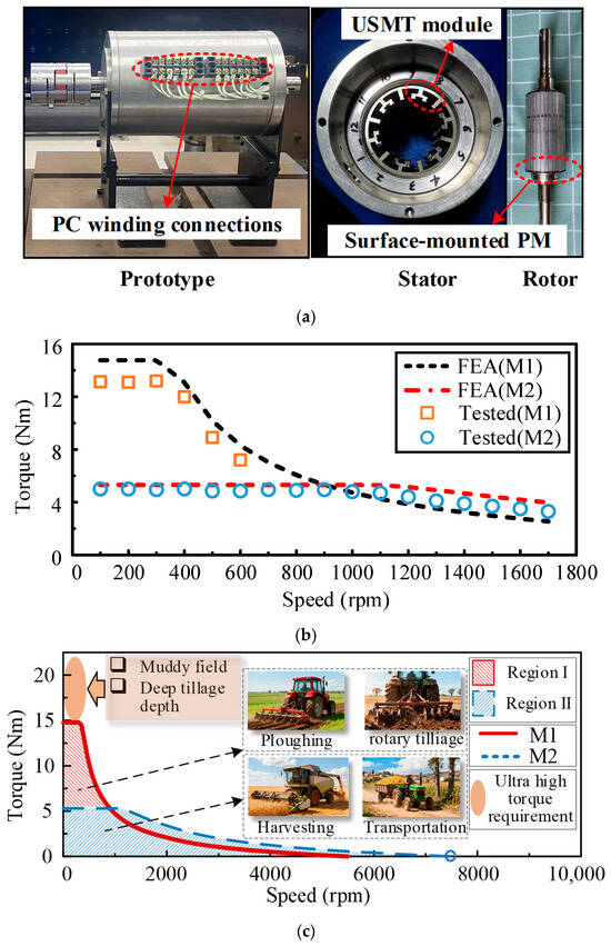
Figure 1.
Prototype and the corresponding experiments of the existing PC-SPMVM: (a) Prototype. (b) Torque–speed curves by FEA and test. (c) Typical operation regions of the motor and ETs.
The typical operation regions of the PC-SPMVM and the ETs are shown in Figure 1c, in which Region I is used for high torque conditions like plowing and rotary tillage, while Region II is used for wide speed operations such as harvesting and transportation. However, muddy field conditions and deep tillage depth both cause a sharp increase in resistance, and ultra-high torque output of the driving motor is required during these extreme, harsh working operations, as shown in Figure 1c. The torque output in M1 of the PC-SPMVM is still limited because of structural limitations.
To further improve the torque density of PC-SPMVM, a PC-DPMVM is proposed and evolved from the PC-SPMVM in this paper. As shown in Figure 2b, the radially inward magnetized surface-mounted PMs on the rotor are replaced by iron teeth so that a consequent-pole structure is obtained. Because of the adoption of iron teeth, the equivalent air-gap length can be decreased to enhance the PM and armature flux density harmonics. Furthermore, PMs with the same magnetized direction as those of the remaining rotor PMs are installed between each two split modulation teeth on the stator, which forms a set of stator PMs. By the modulation effect of the rotor teeth on the stator PMs, the main working PM flux density harmonic in M1 can be enhanced, which further increases the torque output in M1. It should also be mentioned that the PM usage in the proposed PC-DPMVM is similar to that of the existing PC-SPMVM. In other words, half of the rotor surface-mounted PMs are transferred to the stator side during the evolution process as an optimization of PM distribution. Meanwhile, the dimensions of the two motors are marked in Figure 2.
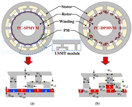
Figure 2.
Motor structures (The magnetization direction of the PMs is indicated by a white arrow) (a) Existing PC-SPMVM. (b) Proposed PC-DPMVM.
To obtain a reasonable comparison, the general design parameters of the two PC-PMVMs are consistent, including slot-pole combination, stator outer diameter, stack length, airgap length, and rated current. It is worth noting that both PC-PMVM motors have been optimized. The optimization objectives are divided into two layers, which can be summarized as follows: for M1, aiming for maximum torque and minimum torque ripple; for M2, aiming for the characteristic current to approach the armature current. The main design parameters of the two motors after optimization are shown in Table 1. It should be noted that material consumption of the PC-DPMVM is larger than that of the PC-SPMVM after optimization.

Table 1.
Main design parameters.
The dimensional parameters of the two motors after optimization are summarized in Table 2.
Table 2.
Main dimensional parameters.
The material and corresponding properties are listed in Table 3. The mesh setting has been made, and the mesh of the two motors is shown in Figure 3. Meanwhile, the boundary conditions, including motion, torque nodal force, FEM coil, iron loss calculation unit, FEM conductor (for PM eddy current loss calculation), and symmetry boundary, are made in the FEA software JMAG 2023.
Table 3.
Material properties.
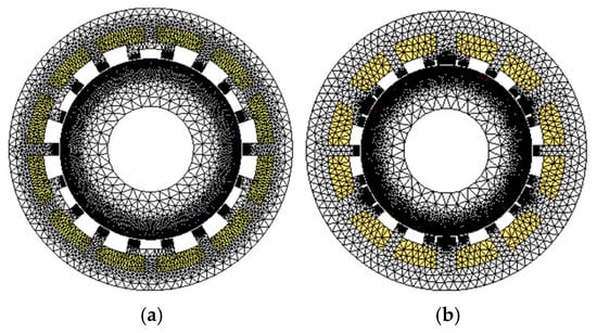
Figure 3.
Partitioned mesh of two motors: (a) PC-SPMVM. (b) PC-DPMVM.
2.2. PM Airgap Field Analysis
As shown in Figure 2b, the PMs serving as the excitation source are distributed on both sides of the rotor and the stator simultaneously in the proposed PC-DPMVM. Therefore, according to the AFMT, both the PM fields produced by the stator-side and rotor-side PMs are modulated by the salient stator and rotor teeth. Moreover, the PM flux density is qualitatively analyzed based on the MMF and permeance models. To simplify the analysis, some assumptions are made as follows: (1) The permeance of the iron core is infinite, and the permeance of PMs is consistent with that of the air. (2) The saturation, flux leakage, and end effect are ignored.
The proposed motor can be regarded as the superposition of two independent single PM excitation motors. Hence, the flux density of the proposed motor can be considered as the flux density of the superposition of a stator PM motor and a rotor PM motor. Subsequently, the proposed motor is disassembled into two independent PM excited motors for flux density analysis.
Firstly, from the perspective of a stator PM motor, considering the modulation of the stator USMT module in the proposed PC-PMVM, the PM magnetomotive force (MMF) with only stator PM excitation is shown in Figure 4a, and the corresponding PM MMF Fs(θ) can be expressed in a Fourier series as
where a0s is the direct current (dc) component of PM MMF, j is a positive integer, and Fmj is the amplitude of the jth PM MMF. PPMs is the pole-pair number of stator PMs; PPMs = 6 in this paper.
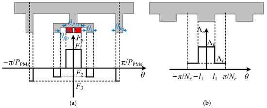
Figure 4.
PM MMF and permeance models of a stator PM motor: (a) Stator PM MMF. (b) Rotor permeance.
In addition, permeance on the rotor side is shown in Figure 4b, according to which the permeance Λr(θ, t) can be expressed as
where k is a positive integer, and Ʌ0r and Ʌmk are the dc component and the kth amplitude of rotor permeance, respectively. Nr is the number of rotor salient teeth, and in this paper, Nr = 17, and θ and ωr are the rotor position angle and mechanical speed, respectively.
Secondly, from the perspective of a rotor PM motor, the PM MMF with only rotor PM excitation Fr(θ, t) can be depicted as Figure 5a and can be derived as
where a0r is the dc component of PM MMF on the rotor side, ν is a positive integer, and Fmν is the amplitude of the νth PM MMF. PPMr is the pole-pair number of rotor PMs; in this paper, PPMr = 17.
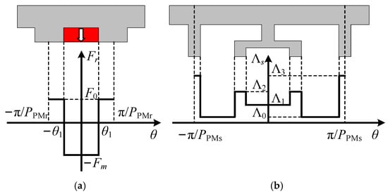
Figure 5.
PM MMF and permeance models of a rotor PM motor: (a) Rotor PM MMF. (b) Stator permeance.
As shown in Figure 5b, the stator-side permeance Ʌs(θ) can be expressed in the Fourier series as
where n is a positive integer, and Ʌ0s and Ʌmn are the dc component and the nth amplitude of stator permeance, respectively.
Therefore, the PM flux density Bg(θ, t) in the airgap field consists of two parts, one of which comes from Fs(θ) modulated by Ʌr(θ, t) to produce stator PM flux density Bs(θ, t), and the other from Fr(θ, t) modulated by Ʌs(θ) to produce rotor PM flux density Br(θ, t). According to the above analysis, Bs(θ, t) and Br(θ, t) can be deduced as
where
Then, by (5) and (6), Bg(θ, t) can be obtained as
For the existing PC-SPMVM, the PM MMF model is shown in Figure 6, and the corresponding stator permeance model is the same as that in Figure 5b. Hence, PM flux density Bc(θ, t) in the airgap field of the existing PC-SPMVM can be written as
where p and q are positive integers, and Ʌ0c and Ʌmq are the dc component and the qth amplitude of stator permeance, respectively. Fmp is the pth amplitude of PM MMF on the rotor side. PPMc and Nmt are the pole-pair number of PMs and the number of stator modulation teeth, respectively.
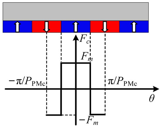
Figure 6.
PM MMF models of the existing PC-SPMVM.
Moreover, Ʌ0r, Ʌmk, Ʌ0s, Ʌmn, Ʌ0c, and Ʌmq can be represented, respectively, as
where α is the ratio of slot opening width bo to slot pitch td, β is a function of bo, as
FCJ is a function of α and represents the magnitude of the J-order harmonic, which can be described as
According to (5)–(8), the field harmonics in the proposed PC-DPMVM can be classified into two categories. As listed in Table 4, there are stationary harmonics with pole-pair number of jPPMs and nPPMs and rotating harmonics with pole-pair number of kNr, |jPPMs ± kNr|, νPPMr, and |νPPMr ± nPPMs|. Since PPMs = 6, PPMr = Nr = 17, the pole-pair number of the stationary harmonics can be summarized as 6j, while the pole-pair number of the rotating harmonics can be summarized as 17k and |6j ± 17k|. It should be noted that the stationary harmonics in the PM field are not involved in generating alternating flux linkage, back electromotive force (EMF), and torque.
Table 4.
Harmonic distribution of PM field.
Meanwhile, according to (9), the field harmonics in the existing PC-SPMVM are all rotating and the pole-pair number of harmonics are pPPMc and |pPPMc ± qNmt|. The harmonics in the existing PC-SPMVM can be concluded as 17p and |17p ± 18q| since PPMc = 17, Nmt = 18.
To simplify the analysis, only the rotating field harmonics with relatively high amplitudes are considered as dominant harmonics for further analysis. Moreover, higher-order components of PM field harmonics are ignored. By using the FEA method, the PM flux density of the two motors is shown in Figure 7. It is obvious that harmonics with pole-pair numbers of 1 (j = 3, k = 1), 17 (ν = 1, n = 0, or p = 1, q = 0), and 35 (j = 3, k = 1) in both motors are the dominant harmonics and are also selected for the following PC design. In addition, 6-, 12-, and 18-pole-pair harmonics emerge in the proposed PC-DPMVM, which is consistent with the theoretical analysis. The proposed motor can provide 40% larger 1-pole-pair harmonic amplitude than the existing PC-SPMVM due to the double-sided PM excitation effect.
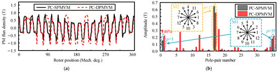
Figure 7.
PM flux density of two motors. (a) Waveform. (b) Spectra.
According to the slot pitch angles, harmonics with pole-pair numbers of 1, 17, and 35 can be divided into two groups: harmonics with pole-pair numbers of 1 and 35 are classified into one group, corresponding to a slot pitch angle of 30°; harmonics with pole-pair number of 17 form a separate group, corresponding to a slot pitch angle of 150°. Then, the slot phasor diagrams of the two groups can be drawn in Figure 7b.
To distinguish the operating modes of these harmonics, their torque output capabilities should be analyzed. Since the output torque is positively correlated with the PM flux linkage, it is necessary to investigate the relationship between the PM flux linkage and harmonics. The PM flux linkage in one coil generated by each PM flux density harmonic ψh(t) can be expressed as
where Bh is the amplitude of h-pole-pair flux density harmonic, Rsi is the stator inner radius, la is the motor axial length, nc is the turn number per coil, θc1 and θc2 are the angles of two coil sides of each coil.
According to (13), the phase PM flux linkage ψph(t) generated by each PM flux density harmonic can be further obtained as
where Nc is the coil number per phase, and kdh, kph, and kwh are the winding distribution, pitch factors, and winding factors of h-pole-pair harmonic. λh is the defined flux linkage weighting factor of h-pole-pair harmonic, which determines the contribution degree of each harmonic, and sgn(h) is the sign function and is related to the initial position and rotating direction of h-pole-pair harmonic.
Whether the slot angle is 30° or 150°, they have the same kwh. Therefore, by (14), ψph(t) is only related to Bh/h. Meanwhile, it can be observed from Figure 7b that the amplitudes of PM flux density with rotating harmonics are close. Therefore, the smaller the value of h, the larger the phase flux linkage and output torque it generates. In other words, the slot pitch angle of 30° for h = 1 and h = 35 corresponds to the high-torque mode (M1), while the slot pitch angle of 150° for h = 17 corresponds to the wide-speed mode (M2). Then, the windings are wound with h = 1 in M1, while the windings are wound with h = 17 in M2.
Similarly, the analysis result of the PC-SPMVM is the same as that of PC-DPMVM.
2.3. Winding Connection
In summary, in both PC-PMVMs, the 1- and 35-pole-pair harmonics belong to M1, and the 17-pole-pair harmonic belongs to M2. The slot pitch angles of M1 and M2 are 30° and 150°, respectively.
According to different phasor diagrams, different coil connections can be obtained in Table 5, in which “+” and “−” represent that the coils are connected in the same and opposite directions, respectively.
Table 5.
Coil connection according to different phasor diagrams.
Then, the PC winding connections of two modes for both motors are shown in Figure 8, where the numbers 1 to 12 correspond to the slot numbers of the stators. When the motor works in M1, the 1- and 35-pole-pair harmonics are selected, while the 17-pole-pair harmonic is filtered out by windings. Conversely, when the motor works in M2, the 17-pole-pair harmonic is selected, and the other harmonics are filtered out. Hence, the two motors can easily achieve PC operation by changing the winding connections for high torque output or wide speed range operation.
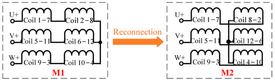
Figure 8.
Winding connections of two modes.
3. Electromagnetic Performance Comparison
In this section, the electromagnetic performances of the two motors are calculated and compared by using the FEA method in terms of the flux linkage, back EMF, inductance, output torque, and speed-widening capability to verify the merits of double-sided PM design.
3.1. PM Flux Linkage and Back EMF
The PM flux linkage waveforms and corresponding spectra of the two motors are shown in Figure 9, in which the amplitudes of the fundamental component of the proposed motor are increased by 38% in M1 and 33% in M2, respectively, than those of the existing one. Moreover, the amplitude of the fundamental component of flux linkage changes markedly before and after PC for both motors, which indicates that the torque and speed regulation range of these two motors may change after PC.
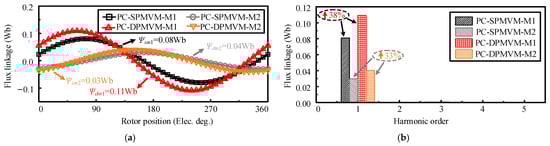
Figure 9.
PM flux linkage of two motors: (a) Waveforms. (b) Spectra.
The back EMF waveforms of the two motors are shown in Figure 10, where the THD values of the no-load back EMF waveforms of PC-SPMVM and PC-DPMVM under M1/M2 are 17.9%/10.0% and 16.4%/8.6%, respectively. It can be observed that the amplitude of fundamental components of the proposed motor is increased by 35% and 36% in M1 and M2, respectively, due to the double-sided PM design, which also implies that the proposed motor will produce higher torque than its counterpart.
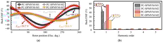
Figure 10.
Back EMF of two motors: (a) Waveforms. (b) Spectra.
3.2. Characteristic Current
The d- and q-axis inductances waveforms of two motors are depicted in Figure 11, where the Ld1/Ld2 and Lq1/Lq2 of PC-SPMVM are 18.7 mH/4.3 mH and 18.7 mH/4.2 mH, respectively. Meanwhile, Ld1/Ld2 and Lq1/Lq2 of PC-DPMVM are 26.5 mH/5.6 mH and 26.5 mH/5.6 mH, respectively. It can be observed that the d- and q-axis inductances of both motors are approximately equal in the same mode, which means that there is little saliency effect in the motor and the id = 0 control strategy is used in the constant torque region. Moreover, from M1 to M2, the d- and q-axis inductances decrease dramatically, which influences the speed range extension capability. The d- and q-axis inductances of the PC-DPMVM are higher than those of the PC-SPMVM because the rotor consequent-pole structure leads to a shorter air-gap length, which increases the inductance. According to the d-axis inductance and the PM flux linkage of M1 and M2 in Figure 9, the characteristic currents in M1 and M2 can be obtained as
where Ic, ψPM1, and Ld are the characteristic current, fundamental amplitude of PM flux linkage, and d-axis inductance, respectively. The subscripts S and D denote PC-SPMVM and PC-DPMVM, respectively, while 1 and 2 correspond to Mode 1 and Mode 2, respectively.
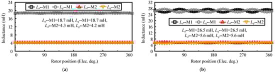
Figure 11.
Inductance of two motors: (a) PC-SPMVM. (b) PC-DPMVM.
Therefore, the characteristic currents of Mode 1 and Mode 2 are 4.3 A and 7.1 A respectively for the PC-SPMVM, while 4.2 A and 7.2 A respectively for the PC-DPMVM. The rated current is determined by linear current density as
where Irms is the RMS value of the current, r is the wire radius, r = 0.58 mm. by (16), Irms ≤ 7.5 A, hence, to achieve a larger output torque, Irms = 7.5 A in this paper.
The inductance and characteristic current of two motors are summarized in Table 6. When the characteristic current is closer to the rated current (7.5 A), the speed regulation ability will be better. Therefore, the speed regulation range of the PC-DPMVM will be wider than that of the PC-SPMVM in M2.
Table 6.
Characteristic current analysis of two motors.
3.3. On-Load Condition
The on-load torques of the two motors under different modes are shown in Figure 12, due to an increase in the fundamental component of back EMF, the average torque of the proposed PC-DPMVM in M1 and M2 are 17.35 Nm and 7.28 Nm, which is 19% and 29% higher than those of the existing PC-SPMVM, respectively. Meanwhile, the torque ripple of the proposed motor is higher than its counterpart in two modes, which is mainly attributed to the increased magnetic saturation due to the use of double-sided PM excitation.
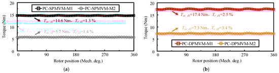
Figure 12.
On-load torque of two motors: (a) PC-SPMVM. (b) PC-DPMVM.
The torque-current curves of the two motors are shown in Figure 13. It can be seen that in M1, the torque output of the PC-DPMVM at 5 A/mm2 is higher than that of the PC-SPMVM, while the torque superiority is decreasing with the increase of current density because of a higher saturation effect. In M2, the torque advantage of the PC-DPMVM is obvious with different current densities. Moreover, the results indicate that compared to PC-SPMVM, the proposed PC-DPMVM maintains effective torque enhancement under higher loads in two modes, thereby demonstrating superior overload capability. The magnetic flux density contour is also shown in Figure 13. It can be seen that the flux density on the stator teeth of the PC-DPMVM is 1.55 T and 1.32 T in M1 and M2, respectively, which are a little higher than those of the PC-SPMVM.
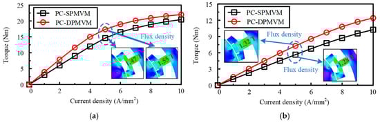
Figure 13.
Torque-current curves: (a) M1. (b) M2.
The temperature distribution of two PMVM motors under two modes are given in Figure 14, Figure 15, Figure 16 and Figure 17. The temperature rises of PMs and windings of PC SPMVM are shown in Figure 18. It can be observed that the temperatures of windings and PMs of PC SPMVM motor under M1 tend to be 34.4 °C and 41.7 °C, respectively, and the temperatures of windings and PMs under M2 tend to be 36.4 °C and 40.0 °C, respectively.
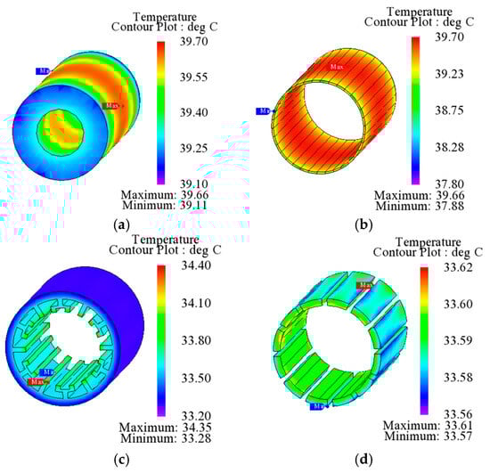
Figure 14.
Temperature analysis results of PC-SPMVM under M1: (a) Rotor. (b) PMs. (c) Stator. (d) Windings.
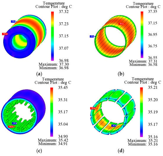
Figure 15.
Temperature analysis results of PC-SPMVM under M2: (a) Rotor. (b) PMs. (c) Stator. (d) Windings.
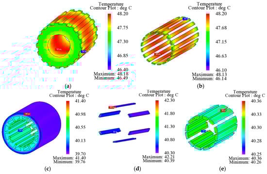
Figure 16.
Temperature analysis results of PC-DPMVM under M1: (a) Rotor. (b) PMs on the rotor side. (c) Stator. (d) Windings. (e) PMs on the stator side.
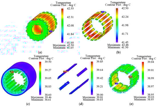
Figure 17.
Temperature analysis results of PC-DPMVM under M2: (a) Rotor. (b) PMs on the rotor side. (c) Stator. (d) Windings. (e) PMs on the stator side.
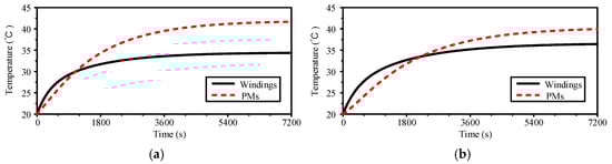
Figure 18.
Temperature rise in PMs and windings of PC-SPMVM: (a) M1. (b) M2.
The temperature rises of PMs and windings of PC DPMVM are shown in Figure 19. It can be observed that the temperatures of windings, rotor-side PMs, and stator-side PMs of PC DPMVM motor under M1 tend to be 41.2 °C, 49.9 °C, and 41.4 °C, respectively, and the temperatures of windings, rotor-side PMs, and stator-side PMs under M2 tend to be 40.6 °C, 45.2 °C, and 40.7 °C, respectively.
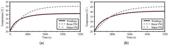
Figure 19.
Temperature rise in PMs and windings of PC-DPMVM: (a) M1. (b) M2.
3.4. Speed Range Regulation Capability
The torque–speed curves are shown in Figure 20, in which the base speeds of the PC-DPMVM in two modes are lower than those of the PC-SPMVM. However, the maximum torques of PC-DPMVM in both modes are improved greatly. Meanwhile, the maximum speed of the proposed PC-DPMVM in M2 is 8350 rpm, which is 12% higher than the PC-SPMVM. The speed ranges of the proposed motor and its counterpart can be expanded by 88% and 35% after PC, respectively. Generally, the proposed PC-DPMVM shows better speed range expansion capability than that of the existing PC-SPMVM. Thus, the proposed PC-DPMVM can be demonstrated to have superior torque and speed range expansion capability.
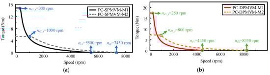
Figure 20.
Torque–speed curves: (a) PC-SPMVM. (b) PC-DPMVM.
Moreover, take the PC-SPMVM motor as an example, a conventional Field-Oriented Control (FOC) strategy is adopted for the motor, which enables high-precision torque and speed regulation even at ultra-low speeds. The minimum stable operating speed of the motor is 30 rpm according to the experimental test. Meanwhile, the FOC strategy is also used for PC-DPMVM, which can fully meet the requirements of low-speed heavy-load operations for electric tractors. Under a DC bus voltage of 150 V, the maximum safe operating speed of the PC-DPMVM motor can reach 8350 r/min, which is constrained only by the DC bus voltage of the supporting inverter (limited by the maximum back-EMF that the inverter can tolerate). In the experimental test, the maximum measurable speed of the test bench is limited to 2000 r/min for safety due to the limitation of the experiment platform.
The comparison of the torque–speed curves of the two motors is shown in Figure 21. It can be seen that the high torque region of the PC-DPMVM is extended due to the double-sided PM excitation effect, as the extra region 1. Moreover, it can be seen from the enlarged figure that there is an extra region 2, which is formed due to the torque improvement in M2. Therefore, not only the maximum torque output in M1, but also the operation region in M2 is extended, which can lead to a more comprehensive operation range.
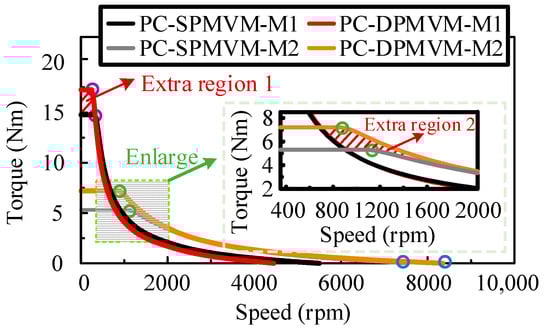
Figure 21.
Torque–speed curves.
The performance comparison of the two motors is shown in Table 7. The maximum torque density of the proposed PC-DPMVM can reach 23.7 kNm/m3 in M1, while the torque density per PM volume is 678.3 kNm/m3. The copper loss in both motors is the same, while the PM eddy loss in the proposed motor is smaller than that of the PC-SPMVM motor. Meanwhile, the iron core loss of the proposed motor in the same mode is larger than that of the PC-SPMVM motor due to the enhanced flux density. Moreover, the proposed motor achieves higher efficiency than the PC-SPMVM motor at rated speed, which is attributed to the enhanced output torque. The maximum speed of the proposed motor is also higher, while the speed regulation ability (the ratio of the maximum speed in M2 to the base speed in M1) can reach 33.4.
Table 7.
Performance comparison of the two motors.
Since the maximum speeds of the two motors under M2 are relatively high, it is necessary to verify the mechanical stress of the two motors at maximum speed. The mechanical stresses at the maximum speeds of 7450 rpm (PC-SPMVM) and 8350 rpm (PC-DPMVM) of the operation regions are simulated using FEA. As shown in Figure 22, the maximum Mises stresses of the PC-SPMVM and the PC-DPMVM are 1.7 MPa and 1.8 MPa, respectively, which are much smaller than that of the yield strength of the iron core (typically 400–410 MPa).
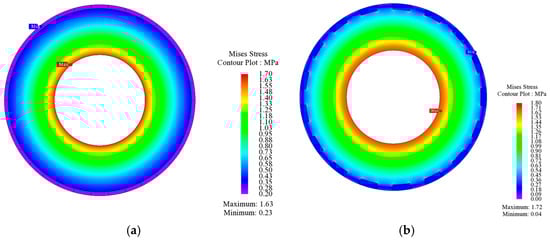
Figure 22.
Mechanical stress at the maximum speed: (a) PC-SPMVM (7450 rpm). (b) PC-DPMVM (8350 rpm).
The efficiency maps with the dc bus voltage Udc = 150 V are shown in Figure 23, where the envelope curves of the two modes are similar to Figure 20. The maximum efficiency of the proposed motor in the same mode is higher than that of the PC-SPMVM motor.
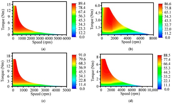
Figure 23.
Efficiency maps with Udc = 150 V: (a) PC-SPMVM (M1). (b) PC-SPMVM (M2). (c) PC-DPMVM (M1). (d) PC-DPMVM (M2).
In summary, compared to the PC-SPMVM motor, the proposed PC-DPMVM motor can not only deliver a higher output torque in M1, but also offer a wider speed range adjustment capability.
4. Conclusions
In this paper, a PC-DPMVM with double-sided PM excitation developed from an existing PC-SPMVM is proposed. Half of the rotor PMs are transferred to the stator small slots, so a consequent-pole rotor structure and stator PM structure can be obtained. Due to the double-sided PM excitation effect, the magnetic field is strengthened, which leads to improvements in the flux density amplitudes of the working harmonics with low pole-pairs, and back EMF amplitude and average torque. The torque density can reach 23.7 kNm/m3, while the speed regulation ability is 33.4, which is 34.7% higher than that of the PC-SPMVM. In addition, two extra operation regions can be obtained by using the double-sided PM excitation effect. That is to say, the proposed PC-DPMVM is superior to the PC-SPMVM in enhancing the output torque of the two modes and achieving a better speed regulation ability. Therefore, it can be verified that the proposed PC-DPMVM is more suitable for the harsh operation conditions of ETs compared with the PC-SPMVM.
The PC-DPMVM serves as the core drive component for medium-sized agricultural tractors, and its main applications include conventional farm operations such as plowing, harrowing, seeding, and medium-load field transportation. Its operating speed range is specifically designed to match the torque–speed characteristics of general tillage operations and transportation operations in agricultural production. Moreover, this design scheme is also applicable to application scenarios requiring the simultaneous achievement of high torque output and a wide speed regulation range, with typical examples including electric vehicle drive systems, elevator traction systems, and marine electric propulsion systems.
Author Contributions
Conceptualization, H.C. and Y.D.; funding acquisition, Y.D.; methodology, H.C., Y.D., and Z.H.; resources, F.X.; software, H.C. and Z.H.; supervision, Y.D. and F.X.; writing—original draft, H.C.; writing—review and editing, Y.D., F.X., and Z.H. All authors have read and agreed to the published version of the manuscript.
Funding
This research was funded by the National Natural Science Foundation of China, grant numbers 52577055 and 52177045.
Data Availability Statement
The original contributions presented in this study are included in the article. Further inquiries can be directed to the corresponding author.
Conflicts of Interest
The authors declare no conflicts of interest.
References
- Lombardi, G.V.; Berni, R. Renewable energy in agriculture: Farmers willingness-to-pay for a photovoltaic electric farm tractor. J. Clean. Prod. 2021, 313, 127520. [Google Scholar] [CrossRef]
- Wang, Y.; Zhu, X.; Yang, D.; Xu, L.; Guo, P.; Chen, W. High efficient cooperation control of distributed motor drive electric tractor considering complex farmland operation conditions. IEEE Trans. Transp. Electrific. 2025, 11, 12719–12732. [Google Scholar] [CrossRef]
- He, Z.; Du, Y.; Xiao, F.; Zhu, X.; Chen, H.; Zhang, C.; Quan, L. Comprehensive performance improvement of permanent magnet vernier motor for electric tractors. IEEE Trans. Transp. Electrific. 2024, 10, 4821–4832. [Google Scholar] [CrossRef]
- Xie, B.; Wang, S.; Wu, X.; Wen, C.; Zhang, S.; Zhao, X. Design and hardware-in-the-loop test of a coupled drive system for electric tractor. Biosyst. Eng. 2022, 216, 165–185. [Google Scholar] [CrossRef]
- Wang, S.; Wu, X.; Zhao, X.; Wang, S.; Xie, B.; Song, Z.; Wang, D. Co-optimization energy management strategy for a novel dual-motor drive system of electric tractor considering efficiency and stability. Energy 2023, 281, 128074. [Google Scholar] [CrossRef]
- Zhao, Y.; Li, D.; Liang, Z.; Qu, R. A high power factor PM vernier machine with segmented stator. IEEE Trans. Transp. Electrific. 2024, 10, 9294–9303. [Google Scholar] [CrossRef]
- Yu, Y.; Pei, Y.; Chai, F.; Doppelbauer, M. Analysis of back EMF harmonics influenced by slot-pole combinations in permanent magnet vernier in-wheel motors. IEEE Trans. Ind. Electron. 2023, 70, 4461–4471. [Google Scholar] [CrossRef]
- Xiang, Z.; Wei, J.; Zhu, X. Torque ripple supression of a PM vernier machine from perspective of time and space harmonic magnetic field. IEEE Trans. Ind. Electron. 2024, 71, 10150–10161. [Google Scholar] [CrossRef]
- Fang, L.; Li, D.; Ren, X.; Qu, R. A novel permanent magnet vernier machine with coding-shaped tooth. IEEE Trans. Ind. Electron. 2022, 69, 6058–6068. [Google Scholar] [CrossRef]
- Jiang, J.; Niu, S.; Li, Z.; Dai, L.; Wu, W.; Chan, W. Design of a novel dual-PM vernier machine for high-torque direct-drive application. IEEE Trans. Transp. Electrific. 2025, 11, 6107–6118. [Google Scholar] [CrossRef]
- Jiang, J.; Niu, S.; Zhang, X. Torque improvement of a hybrid-excited vernier reluctance machine with high-order-harmonic winding design for electric vehicle application. IEEE Trans. Transp. Electrific. 2024, 10, 2397–2407. [Google Scholar] [CrossRef]
- Meng, Y.; Fang, S.; Pan, Z.; Liu, W.; Qin, L. Design and analysis of a new partitioned stator hybrid-excited flux reversal machine with dual-PM. IEEE Trans. Magn. 2022, 58, 8100806. [Google Scholar] [CrossRef]
- Cai, S.; Zhu, Z.; Mipo, J.; Personnaz, S. Investigation of novel doubly salient hybrid excited machine with non-overlapped field winding. IEEE Trans. Energy Convers. 2021, 34, 2261–2275. [Google Scholar] [CrossRef]
- Yang, H.; Zhu, Z.; Lin, H.; Lyu, S. Comparative study of hybrid PM memory machines having single- and dual-stator configurations. IEEE Trans. Ind. Electron. 2018, 65, 9168–9178. [Google Scholar] [CrossRef]
- Xu, L.; Zhu, X.; Wu, W.; Fan, W.; Zhou, X.; Cai, X.; Quan, L. Flux-leakage design principle and multiple-operating conditions modeling of flux leakage controllable PM machine considering driving cycles. IEEE Trans. Ind. Electron. 2022, 69, 8862–8874. [Google Scholar] [CrossRef]
- Yan, Y.; Fan, Y.; Shen, F.; Chen, H.; Cai, S.; Yuan, X.; Lee, C.H. Hybrid-magnet variable flux memory machine with improved field regulation capability for electric vehicle applications. IEEE Trans. Transp. Electrific. 2023, 9, 586–597. [Google Scholar] [CrossRef]
- Fan, W.; Zhu, X.; Quan, L.; Wu, W.; Xu, L.; Liu, Y. Flux-weakening capability enhancement design and optimization of a controllable leakage flux multilayer barrier PM motor. IEEE Trans. Ind. Electron. 2021, 68, 7814–7825. [Google Scholar] [CrossRef]
- Tu, R.; Yang, H.; Lin, H.; Zhan, H.; Wu, D.; Yu, M. Design and optimization of a novel delta-type consequent-pole hybrid magnet memory machine. IEEE Trans. Energy Convers. 2024, 39, 1265–1277. [Google Scholar] [CrossRef]
- Osama, M.; Lipo, T.A. Experimental and finite-element analysis of an electronic pole-changing drive. IEEE Trans. Ind. Appl. 2000, 36, 1637–1644. [Google Scholar]
- Fuchs, E.F.; Schraud, J.; Fuchs, F.S. Analysis of critical-speed increase of induction machines via winding reconfiguration with solid-state switches. IEEE Trans. Energy Convers. 2008, 23, 774–780. [Google Scholar] [CrossRef]
- Mallampalli, S.; Zhu, Z.Q.; Mipo, J.C.; Personnaz, S. Six-phase pole-changing winding induction machines with improved performance. IEEE Trans. Energy Convers. 2021, 36, 534–546. [Google Scholar] [CrossRef]
- Cheng, M.; Han, P.; Hua, W. General airgap field modulation theory for electrical machines. IEEE Trans. Ind. Electron. 2017, 64, 6063–6074. [Google Scholar] [CrossRef]
- Ma, Z.; Cheng, M.; Wen, H. Analysis and optimization of rotor salient pole reluctance considering multi-modulation orders. IEEE Trans. Ind. Electron. 2023, 70, 10871–10880. [Google Scholar] [CrossRef]
- Mao, Y.; Du, Y.; Xiao, F.; Zhu, X.; Quan, L.; Zhou, D. Design and optimization of a pole changing flux switching permanent magnet motor. IEEE Trans. Ind. Electron. 2023, 70, 12636–12647. [Google Scholar] [CrossRef]
- Du, Y.; He, Z.; Zhu, X.; Xiao, F.; Zhang, C.; Xu, L.; Zuo, Y.; Quan, L. A novel pole-changing permanent magnet vernier motor. IEEE Trans. Ind. Electron. 2023, 70, 6110–6120. [Google Scholar] [CrossRef]
- Zhang, C.; Li, J.; Li, C.; Lin, P.; Shi, L.; Xiao, B. Electrification and smartification for modern tractors: A review of algorithms and techniques. Agriculture 2025, 15, 1943. [Google Scholar] [CrossRef]
Disclaimer/Publisher’s Note: The statements, opinions and data contained in all publications are solely those of the individual author(s) and contributor(s) and not of MDPI and/or the editor(s). MDPI and/or the editor(s) disclaim responsibility for any injury to people or property resulting from any ideas, methods, instructions or products referred to in the content. |
© 2026 by the authors. Licensee MDPI, Basel, Switzerland. This article is an open access article distributed under the terms and conditions of the Creative Commons Attribution (CC BY) license.