Article

Kinematics and Stiffness Analysis of a Novel 5-DOF Parallel Mechanism

College of Mechanical and Electrical Engineering, Hebei Normal University of Science & Technology, Qinhuangdao 066000, China
*
Author to whom correspondence should be addressed.
Electronics 2025, 14(17), 3400; https://doi.org/10.3390/electronics14173400
Submission received: 30 July 2025 / Revised: 25 August 2025 / Accepted: 25 August 2025 / Published: 26 August 2025

Abstract

A novel five-degrees-of-freedom (DOF) P(2PRPU)/PRPS double-driven parallel mechanism (PM) is proposed in this study, and its kinematics and stiffness are studied systematically. First, the structural configuration is described, and the degrees of freedom of the parallel mechanism are analyzed based on constraint conditions. Next, the position model, velocity model, and Jacobian matrix are derived, and the workspace and kinematic performance of the mechanism are studied. Third, based on the principle of virtual work, a static model and a deformation decomposition method are employed to construct the stiffness model, resulting in the corresponding stiffness and compliance matrices. Finally, the stiffness performance of the mechanism is analyzed using the derived compliance matrix. This study is expected to provide new insights for the design of machining tools.

1. Introduction

In the aerospace, transportation, and shipbuilding industries, core structural components are typically complex parts characterized by freeform surfaces. The efficient and high-quality machining of such components has emerged as a global technical challenge in the field of intelligent manufacturing. Owing to their geometric complexity, these freeform surface components generally require five-axis machining. Consequently, the development of high-performance five-axis machining equipment for complex surface parts has become a primary research focus and strategic priority in these key industries [1].
Parallel mechanisms, as a class of mechanical systems composed of multiple independent kinematic chains, connect the moving platform (end-effector) to the fixed base through at least two closed-loop kinematic chains. Compared to traditional serial mechanisms, parallel mechanisms exhibit significant advantages, including high structural stiffness, rapid dynamic response, superior positioning accuracy, and strong reconfigurability, making them highly promising for precision machining applications [2,3]. Currently, parallel mechanism-based machining robots are primarily categorized into three types based on their degrees of freedom (DoF): 3-DoF [4,5,6], 4-DoF [7,8], 5-DoF [9,10], and 6-DoF [11] configurations. Among these, 3-DoF parallel mechanisms require an additional 2-DoF serial module to achieve five-axis machining capabilities. However, such hybrid configurations cannot fully overcome the inherent drawbacks of serial mechanisms, such as low stiffness and error accumulation. On the other hand, while 6-DoF parallel mechanisms offer full functionality, they suffer from structural complexity, high manufacturing costs, and increased control challenges. In contrast, 5-DoF parallel mechanisms, with their fully parallel topology, not only meet the essential DoF requirements for five-axis machining but also retain the high stiffness and precision characteristics of parallel mechanisms, demonstrating unique advantages in the high-efficiency and high-precision machining of complex curved components. Therefore, research on 5-DoF parallel robots holds significant value for advancing high-performance machining equipment [12,13].
In traditional parallel mechanisms, the number of degrees of freedom (DOFs) is typically equal to the number of branches with actuated joints. In other words, the number of actuated limbs directly corresponds to the dimensionality of the mechanism’s motion. As a result, a 5-DOF parallel mechanism generally requires the deployment of five limbs. However, such a large number of limbs not only increases the complexity of the mechanism’s topology but also raises the risk of interference among the branches. To address these issues, dual-actuated parallel mechanisms have emerged as a novel configuration that has attracted growing interest in the academic community. Li et al. [14] proposed a composite CRR limb capable of both translation and rotation, which was then combined with a UUR limb to construct a 3-DOF single-loop CRRUUR PM. Subsequently, they employed this CRRUUR PM as a robotic leg to develop a novel quadruped robot. Li et al. [15] introduced a cylindrical drive (c-drive) based on an RHHR kinematic chain, enabling cylindrical motion. Utilizing this C-drive, they designed a 6-DOF parallel robot with a 3-CPS topology, named SDelta, in which all actuators are mounted on the base to eliminate limb interference while minimizing inertial loading. Wang et al. [16] developed a redundantly actuated PM and established its dynamic model using the closed-loop vector method and Lagrangian formulation. The validity of the model was confirmed through comparative simulations in MATLAB and Adams. Lu et al. [17] presented a novel 5-DOF hybrid rotational/linear 2UPS-SPR PM, deriving its velocity, static force, and acceleration equations while systematically analyzing its workspace, kinematics, and statics. Rong et al. [18] proposed a 5-DOF PM with three limbs, featuring a semi-symmetric architecture where some actuated limbs are mounted on the base to reduce inertial effects significantly. As an emerging research field, dual-drive parallel mechanisms are still in the exploratory stage, with their configuration design and theoretical analysis posing open challenges that require further investigation.
In summary, research on dual-driven parallel mechanisms is still in its early stages and holds broad application prospects. Based on the concept of dual actuation, a new type of P(2PRPU)/PRPS PM is proposed in this paper. The innovation lies in the use of only three dual-actuated branches, which significantly reduces branch interference. Furthermore, the first-stage actuated joints of the dual-driven branches are arranged on the base, greatly minimizing the impact of inertial loads on the structure. Compared with existing five-degree-of-freedom parallel mechanisms, the proposed mechanism has only three branches and 17 single-degree-of-freedom kinematic pairs in total, offering a simpler structure. Combined with the visual system, this new PM can be applied to the sorting of electronic components on engineering assembly lines in the future.
Stiffness, defined as the ability of a structure to resist elastic deformation, is a critical factor in PM research as it directly influences dynamic performance and positioning accuracy. Consequently, this field has attracted significant attention from researchers. Li et al. [19] proposed a novel 3-DOF RPU + UPU + SPU PM and conducted a systematic investigation of its complete kinematics and stiffness characteristics. Ma et al. [20] introduced bending stiffness and torsional stiffness as key metrics for evaluating the stiffness of 2R1T PMs. Based on the stiffness evaluation indices and methods, the stiffness performance of five 2R1T PMs is compared and analyzed. Hu et al. [21] examined the relationship between wrenches and corresponding deformations using a deformation and force decomposition method, establishing a unified stiffness model for three types of 4-DOF over-constrained PMs. Xue et al. [22] developed a theoretical stiffness model for a novel spatially redundant 3-PRPS PM with three relative DOFs, incorporating both internal forces and external loads, and further visualized stiffness variations across the workspace. Raoofian et al. [23] formulated a stiffness model for the Delta PM, extracting four key indices from the stiffness matrix to evaluate both translational and rotational deformations. However, research on the stiffness of dual-drive parallel mechanisms remains scarce, providing strong motivation for the present study.
For these reasons, this study proposes a novel dual-drive PM. The complete kinematics and stiffness analysis of this novel PM are carried out, and the results could provide new ideas for the design of PM machine tools. This paper is organized as follows. In Section 2, the proposed PM is introduced, and its constraint conditions and DOFs are analyzed. In Section 3, a 5 × 5 Jacobian matrix is derived to analyze its workspace and kinematic performance. In Section 4, a stiffness model of the mechanism is established, and based on this model, the stiffness performance of the mechanism is analyzed. The conclusions are presented in Section 5.

2. Description and Mobility Analysis

2.1. Configuration Description

The proposed PM includes a moving platform m, a base platform B, two identical PRPU (prismatic joint–revolute joint–prismatic joint–universal joint) chains, one PRPS (prismatic joint–revolute joint–prismatic joint–universal joint) chain, and a separate prismatic joint P, as shown in Figure 1. Here, m is an isosceles triangle with three vertices Ci (i = 1, 2, 3), Ai denote the rotation centers of the revolute joints, B is a rectangle with four vertices, three double-driven chains are arranged on three sides of the rectangle, and the first prismatic joint of the PRPU and PRPS double-driven chains is mounted on the base frame.
As depicted in Figure 1, let O-XYZ (denoted as {B}) denote the fixed frame established at the midpoint O of the short edge of B; here, the X-axis is aligned with the short edge of B, the Y-axis is parallel to the long edge, and the Z-axis is normal to B. Denote o-xyz (denoted as {m}) as the moving frame. o is the midpoint of C2C3. The y-axis is collinear with C2C3, the z-axis is perpendicular to m, and the x-axis is oriented according to the right-hand rule. The RPU within the PRPU chains is defined as chain ri (i = 2, 3). Since points A2 and A3 move synchronously along the X-direction, the prismatic joints arranged on B in the two PRPU chains can be driven by a single chain rX, which consists of prismatic joint P which has a motion direction collinear with the X-axis. Similarly, the prismatic joint arranged on the base in the PRPS chain is defined as chain rY, and the RPS is defined as r1.
Let ⊥ denote perpendicular constraint, | and ǁ denote collinear and parallel constraint, respectively. Let Rij (i = 1, 2, 3; j = 1, 2) denote the j-th R joint in the i-th ri. Based on the geometrical constraints, the following relationships can be written:
r Y | Y ,   R 11 | Y ,   r 1 Y ,   r X | X ,   A 2 A 3 Y r i R i 1 ,   R i 1 R i 2 ,   R i 2 R i 3 ,   R i 3 | y     R 22 R 32   i = 2 , 3

2.2. Mobility Analysis

For the lower mobility PMs, the constrained wrenches (forces/torques) exist in the legs. The following rules can determine the constrained wrenches: In each chain, the constrained forces should be perpendicular to all P joints and coplanar with all R joints; the constrained torques should be perpendicular to all R joints. Based on the geometric constraint relationship in Section 2.1, for the PRPU chain, there is one constrained torque, Tci, which is perpendicular to Ri2 and Ri3. To simplify the expression, denote that δi is the unit vector of ri, ei is the vector from o to Ci, Tci is the value of Tci, τci is the unit vector of Tci, τc2 = R22 × R23,τc3 = R32 × R33, and τc2 ǁ τc3 ǁ z. As a result, the 2PRPU/PRPS PM is constrained solely by a constrained torque along the z-axis, and the DOF of the P(2PRPU)/PRPS PM always remains 2R3T.

3. Kinematics Analysis

3.1. Kinematic Modeling

Let BRm be the rotational matrix of relative {B} to {m}, α and β are two Euler angles about corresponding axes, then BRm can be expressed explicitly as follows:
R m B = R X α R Y β =       c β             0               s β     s α s β         c α       s α c β c α s β           s α           c α c β
where sθ = sin(θ), cθ = cos(θ), with θ being α or β, let Ai and Ci (i = 1, 2, 3) be the vector of Ai and Ci in {O-XYZ}. Based on the mechanism architecture, Ai and Ci can be expressed as follows:
A 1 = 0 e 1 s α s β + y 0 , A 2 = x 0.5 L 0 , A 3 = x 0.5 L 0 , o = x y z C 1 = R B m h 0 0 + o ,     C 2 = R B m 0 0.5 e 0 + o ,     C 3 = R B m 0 0.5 e 0 + o L = A 2 A 3 , e = C 2 C 3 , h = o C 1
Let li represent the length of the ri. From Equation (4), li can be derived in the following manner:
l 1 2 = e 1 c β +     x 2 +   e 1 c α s β + z 2 , l 2 2 = e 2 c α + y L 2 + e 2 s α + z 2 l 3 2 = e 3 c α + y + L 2 + e 3 s α + z 2 , l x = x ,   l y = e 1 s α s β + y  
Denote the linear velocity v of point o relative to O, the angular velocity ω of {m} relative to {B}. The relations between V (V = [v ω]T) and V P = x ˙   y ˙   z ˙   α ˙   β ˙   T are expressed as follows:
v = J v V P ,   J v = 1 0 0 0 0 0 1 0 0 0 0 0 1 0 0 ,   V P = x ˙   y ˙   z ˙   α ˙ β ˙  
ω = R α α ˙ + R β β ˙ = J ω V P ,   J ω = 0 0 0 1 0 0 0 0 0 c α 0 0 0 0 s α
Define vi as the linear velocity of Ci, which can be expressed as follows:
v i = v + ω × e i , e i = C i o
Denote vri as the active velocities of ri, which can be expressed as follows:
v r i = v i δ i = v + ω × e i i = v δ i + ω × e i δ i         = δ i T   e i × δ i T   V ,   δ i = r i / l i ,   i = 1 , 2 , 3
For rX and rY, the closed-loop constraint equation associated with each branch chain can be written as follows:
l Y δ Y + l 1 δ 1 e 1 = o l X δ X + l i δ i e i = o ,   i = 2 , 3
Differentiating Equation (9) with respect to time leads to the following:
v r Y δ Y + v r 1 δ 1 + ω 1 × l 1 δ 1 ω × e 1 = v v r X δ X + v r i δ i + ω i × l i δ i ω × e i = v
where ωi (i = 1, 2, 3) is the angular velocity of branch ri. Dot multiply both sides of Equation (10) by δX and δY, respectively, to obtain the following:
v r Y + δ Y ω 1 × l 1 δ 1 δ Y ω × e 1 = δ Y T v v r X + δ X ω i × l i δ i δ X ω × e i = δ Y T v
The angular velocity of ri can be expressed as follows:
ω 1 = δ Y θ ˙ 1 ,   ω i = δ X θ ˙ i ,   i = 2 ,   3
here, θ ˙ i is the rotational velocity of the rotation around the axis of the revolute joint.
Substitute Equation (12) into Equation (11) to obtain the following:
v r Y δ Y × e 1 T ω = δ Y T v v r X δ X × e i T ω = δ X T v ,   i = 2 , 3
Then, combining Equations (8) and (13) leads to the following:
v r X v r Y v r 1 v r 2 v r 3 = J m v ω ,   J m = J X J Y J 1 J 2 J 3 = δ X T     e 2 × δ X T δ Y T     e 1 × δ Y T δ 1 T     e 1 × δ 1 T δ 2 T     e 2 × δ 2 T δ 3 T     e 3 × δ 3 i T
By substituting Equations (5) and (6) into Equation (14), the velocity model of can be obtained:
v r X v r Y v r 1 v r 2 v r 3 = J D x ˙ y ˙ z ˙ α ˙ β ˙ , J D = J m J B , J B = J v J ω
When x ˙ ,   y ˙ , z ˙ ,   α ˙ ,   β ˙ are obtained, the actuation velocity of ri can be obtained according to Equation (15).

3.2. Kinematic Performance Analysis

3.2.1. Workspace Analysis

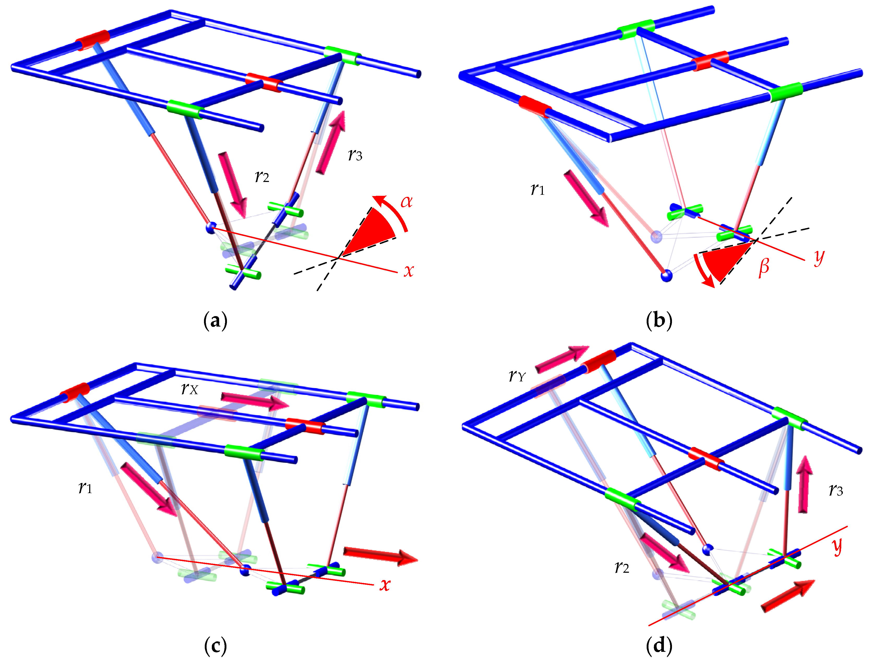
The workspace of a PM refers to the set of points that its moving platform is capable of reaching. The size and shape of this region directly influence the performance of the PMs. As a result, the analysis and determination of the workspace constitute a central aspect in evaluating the overall performance of PMs. For the proposed PM, when the m rotates around the X-axis, the driving branches are r2 and r3, as shown in Figure 2a; when the m rotates around the Y-axis, the driven branch is r1, as shown in Figure 2b. When the m is translated along the Z-axis, the driving branches are r1, r2, and r3. When the m is translated along the X-axis, the driving branches are rX and r1, as shown in Figure 2c. When the m is translated along the Y-axis, the driving branches are rY, r2 and r3, as shown in Figure 2d.
From the above analysis, it can be seen that when the mobile platform moves in different directions, the participation of the five side chains shows certain differences. Considering the constraint of the connecting rod length, it will lead to different movement ranges of the mechanism along different degrees of freedom, thereby affecting the distribution of the working space of the mechanism. In this paper, the Monte Carlo method is employed to determine the workspace of the PM. This approach involves substituting randomly generated pose parameters into the mathematical model to assess whether the predefined constraints are satisfied. When the constraints are met, the corresponding pose parameters are recorded, resulting in a collection of spatial positions of point o in three-dimensional space. The spatial position of the moving platform is represented by the coordinates of point o, which denotes the reference point on the platform. The relevant structural parameters are the following: L = 1200 mm, e = 400 mm, h = 240 mm. The constraints include setting the length limit of the drive branch chain and the rotation angle limit of the kinematic joint, among which the length limit is the following:
990   mm l i 1490   mm ,   i = 1 , 2 , 3 600   mm l x 1600   mm                           l y 700   mm
For the revolute joint Ri1 (i = 1, 2, 3), the angular constraint is defined as the angle θi between the vector δi and the Z-axis, and the angular constraint condition can be expressed as follows:
θ i 60 ,   θ i = arccos δ i Z δ i Z ,   Z = [ 0   0   1 ] T
For the spherical joint S, the angular constraint is defined as the angle Sθ between the vector δ1 and the z-axis, and the angular constraint condition of the S joint can be expressed as follows:
S θ 30 ° ,   S θ = arccos δ 1 z δ 1 z
For the universal joint Ui (i = 2, 3), the angular constraint is defined as the angle Uθi between the vector δi and the z-axis, and the angular constraint condition of the Ui joint can be expressed as follows:
U θ i 30 ° , U θ i = arccos δ i z δ i z
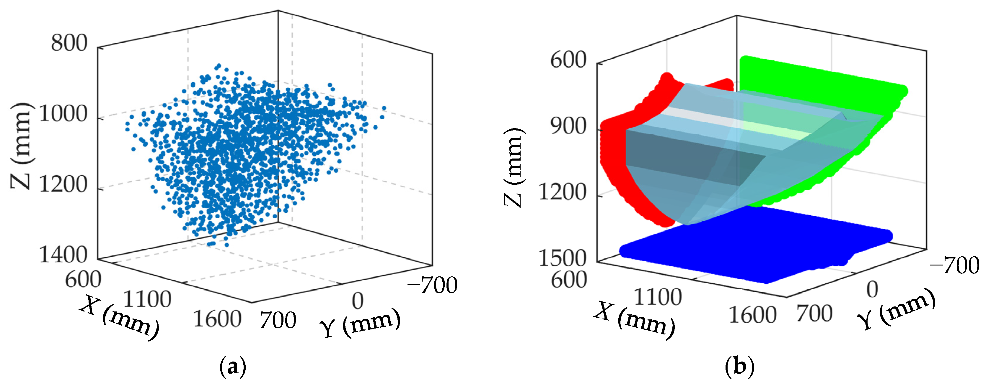
A theoretical kinematic model of the parallel mechanism was established using MATLAB (2018b). Based on the structural parameters of the mechanism and the constraint conditions defined in Equations (16)–(19), the Monte Carlo method was applied to generate pose parameters that satisfy the constraints. These discrete pose points form a three-dimensional point cloud representing the reachable positions of point o in space. Subsequently, boundary points were extracted from the point cloud and connected to form a series of closed curves. Finally, these curves were swept to generate an enveloping surface, resulting in a three-dimensional solid representation of the workspace. This solid volume defines the theoretical workspace of the P(2PRPU)/PRPS PM.
Figure 3 illustrates the workspace of the P(2PRPU)/PRPS PM. In Figure 3a, the point cloud is obtained under the imposed constraints using the Monte Carlo method. From its distribution in three-dimensional space, the overall outline of the workspace can be roughly observed, although the boundary is not well defined. By extracting the boundary points and generating the corresponding three-dimensional solid, as shown in Figure 3b, the external contour of the workspace is more clearly represented.
As shown in Figure 3b, the overall workspace is approximately a quarter sphere. Since the minimum length of r1 is 990 mm, the workspace along the X-axis does not start from X = 0 but is offset by a certain distance. In the Y-axis direction, the red projection of the workspace on the X = 600 mm plane in Figure 3b is symmetrical with respect to the Y = 0 axis, reflecting the semi-symmetrical structural characteristics of the P(2PRPU)/PRPS PM. From a global perspective, the workspace extends farther along the Y-axis, indicating that this is the main working direction of the mechanism.

3.2.2. The Analysis of Transmission Performance

The transmission performance of a PM is closely correlated with the pressure angle of its branched chains. The pressure angle is defined as the acute angle between the direction of the transmitted force and the velocity of the point of application on the driven member. From the standpoint of mechanical transmission efficiency, a smaller pressure angle indicates that a greater portion of the force contributes to motion along the velocity direction, thereby resulting in improved transmission performance and higher efficiency. Conversely, a larger pressure angle tends to degrade transmission performance and reduce efficiency accordingly.
Considering that the driving joints of the P(2PRPU)/PRPS PM are prismatic joints, each branched chain of the mechanism is actuated by an independent driving force. The direction of the driving force in each branched chain is always aligned with the axis of the prismatic joint. Therefore, at any given pose, there exists an angle α between the driving force direction at the end of the branch ri and the velocity direction of the end-points of the moving platform. This angle ζ is defined as the pressure angle of the corresponding branch ri.
Based on Equation (19), the cosine of the transmission pressure angle for each branched chain is defined as the transmission performance index of that branched chain i:
μ i = δ i δ C i = cos ζ i ,   δ C i = v i v i
When the transmission performance index of a branch approaches 1, it indicates that the mechanism exhibits higher transmission efficiency. Conversely, a lower value corresponds to reduced transmission efficiency. The transmission efficiency index ranges from 0 to 1. In order to ensure effective power transmission from each limb to the moving platform, the minimum value of cos should be as large as possible. Since, in the P(2PRPU)/PRPS PM, only branched chains r1, r2, and r3 are directly connected to the moving platform, the transmission performance index of the P(2PRPU)/PRPS PM is defined as follows:
μ = min cos ζ 1 , cos ζ 2 , cos ζ 3
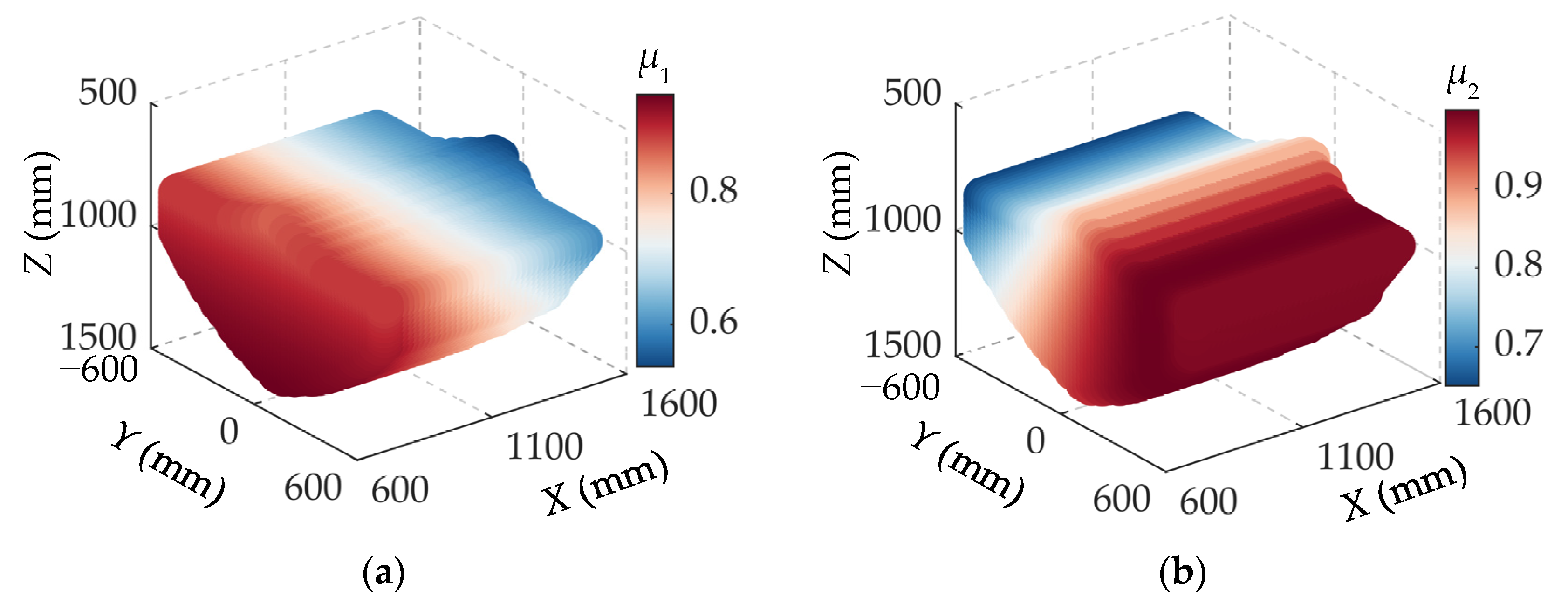
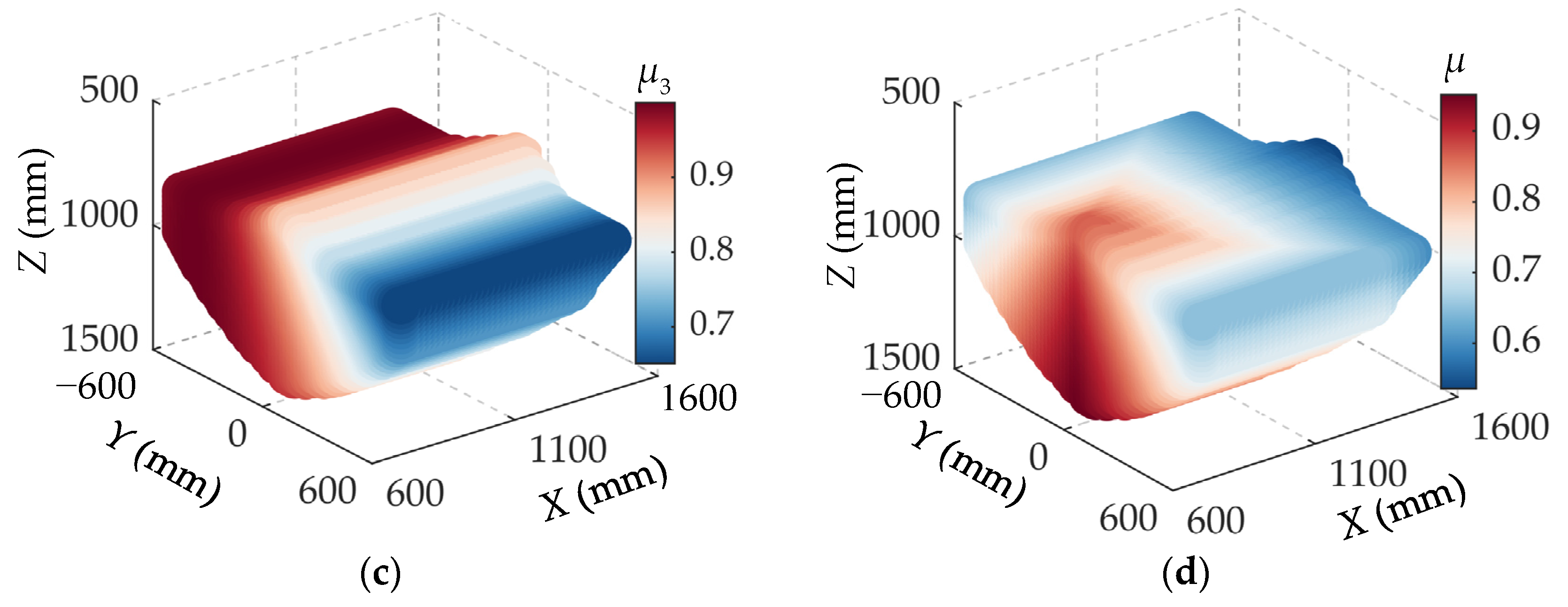
Figure 4 illustrates the distribution characteristics of the transmission performance indices for individual branches as well as for the overall PM within its workspace. As shown in Figure 4a, the transmission performance index μ1 of branch r1 exhibits a symmetrical distribution along the X-axis in the Y = 0 plane and gradually decreases with increasing X-coordinate. The transmission performance indices μ2 and μ3 of branches r2 and r3 display a mirror-symmetric variation. Specifically, when the moving platform is located in regions corresponding to shorter branch lengths, the transmission performance indices are relatively high; conversely, in regions corresponding to longer branch lengths, the indices decrease noticeably.
From Figure 4a–c, it can be observed that the transmission performance indices μi of individual branches are negatively correlated with their respective branch lengths: the farther the moving platform is from a given branch, the lower its transmission performance index. Furthermore, Figure 4d indicates that the optimal transmission performance region of the mechanism is concentrated near the initial position of the workspace. As the absolute values of the X- and Y-coordinates increase, the transmission performance indices gradually decline, indicating a reduction in overall transmission performance. Therefore, from the perspective of transmission performance, the primary operating range of the moving platform should be limited to the central initial region of the workspace.

4. Stiffness Analysis

4.1. Stiffness Modeling

In the P(2PRPU)/PRPS PM, the driving force from the independent actuated branch chain rX can be uniformly distributed to the passive branch chain s r2X and r3X of the two PRPU branches. Therefore, for stiffness modeling and analysis, this mechanism can be equivalently simplified as a 2PRPU/PRPS PM model.
Let m be elastically suspended by an elastic linear branch chain (r1 r2 r3 r2X r3X rY) while all joints are considered rigid bodies. The relations between the active forces (Fai) (i = 1, 2, 3, a2x, a3x, Y), the constrained torque (TCi) (i = 2, 3), and the loading force/torque (F/T) can be expressed as follows:
F T = G 6 × 8 F c , F c = F a T c , F a = F a 1   F a 2   F a 3   F a 2 x   F a 3 x   F ay T T c = T c 2   T c 3 T G 6 × 8 = δ 1 δ 2 δ 3 X X Y 0 3 × 1 0 3 × 1 e 1 × δ 1 e 2 × δ 2 e 3 × δ 3 e 2 × X e 3 × X e 1 × Y R 22 × R 23 R 32 × R 33
Here, X = [1 0 0]T, Y = [0 1 0]T. For the PRPU branch chain, the constrained torque Tci (i = 2, 3) can be decomposed into two component torques: Trni and Trwi. Here, Trni represents the component torque of Tci along the branch chain axis, while Trwi denotes the component torque of Tci perpendicular to the branch chain axis. Let τci, τrni, and τrwi be the unit direction vectors of Tci, Trni, and Trwi, respectively. From the geometrical constraints of the PRPU branch chain, this leads to the following:
τ rni = δ i , τ rwi δ i , τ ci R i 2 , τ rni R i 2 , i = 2 , 3
τci, τrni, and τrwi are in the same plane. The following geometrical constraints must be satisfied:
τ rwi R i 2 , τ rwi = δ i × R i 2
Let Tci, Trni, and Trwi denote the magnitudes of Tci, Trni, and Trwi, respectively. From Equation (23), Trni can be expressed as follows:
T rni = T ci τ rni = T ci τ ci δ i = T ci s in ,   s in = τ ci δ i ,   i = 2 , 3
From Equation (24), Trwi can be expressed as follows:
T rwi = T ci δ i × R i 2 = T ci τ ci δ i × R i 2 = T ci s iw ,   s iw = τ ci δ i × R i 2
From Equations (25) and (26), we obtain the following:
F s = W 10 × 8 F c , F c = F a 1   F a 2   F a 3   F a 2 x   F a 3 x   F a y   T c 2   T c 3 T F s = F a 1   F a 2   F a 3   F a 2 x   F a 3 x   F a y   T r n 2   T r w 2   T r n 3   T r w 3 T W 10 × 8 = E 6 × 6     0 6 × 2 0 2 × 6     G 2 0 2 × 6     G 3 G 2 = s 2 n     0 s 2 w     0 ,   G 3 = 0     s 3 n 0     s 3 w
Let δri (i = 1, 2, 3, 2X, 3X, Y) be the elastic deformation along ri due to the active Fai, leading to the following:
F ai = k ri δ r i ,   k ri = E s S i l i ,   δ r i = F ai l i E s S i
Here, Es is the modulus of elasticity and Si is the area of ri.
Let δθrni be the torsional deformation about ri due to Trni, δθrwi be the torsional deformation about ri due to Trwi (i = 2, 3). The relationship between Trni and δθrni in the i-th branch chain can be expressed as follows:
T rni = k rni δ θ rni ,   k rni = G I c l i ,   δ θ rni = T rni l i G I c
Here, G is the shear modulus and Ic is the polar moment of inertia. The relationship between Trwi and δθrwi in the i-th branch chain can be expressed as follows:
T rwi = k rwi δ θ rwi ,   k rwi = E s I l i ,   δ θ rwi = T rwi l i E s I
where I is the moment inertia.
From Equations (27)–(30), we obtain the following:
F s = K 10 × 10 r δ Ψ F s = F a 1   F a 2   F a 3   F a 2 x   F a 3 x   F a y   T r n 2   T r w 2   T r n 3   T r w 3 T δ Ψ = δ r 1   δ r 2   δ r 3 δ r 2 X   δ r 3 X   δ r Y   δ θ rn 2   δ θ rw 2   δ θ rn 3   δ θ rw 3 T K 10 × 10 r = diag k r 1     k r 2     k r 3     k r 2 x     k r 3 x     k Y     k rn 2     k rw 2     k rn 3     k rw 3
Let [δx δy δz δΦx δΦy δΦz] represent the microdeformation of m, leading to the following:
F s T δ Ψ = F T     T T δ p δ Φ
Substituting Equation (27) into (32), we obtain the following:
W 10 × 8 F c T δ Ψ = F c T W 10 × 8 T δ Ψ = F T     T T δ p δ Φ = F c T G 6 × 8 T δ p δ Φ
Substituting Equation (31) into (33) leads to the following:
W 10 × 8 T K 10 × 10 r 1 W 10 × 8 F c = G 6 × 8 T δ p δ Φ
Furthermore, from Equations (22) and (33), we obtain the following:
F T = K δ p δ Φ , K = G 6 × 8 W 10 × 8 T K 10 × 10 r 1 W 10 × 8 1 G 6 × 8 T
where K is the stiffness matrix.
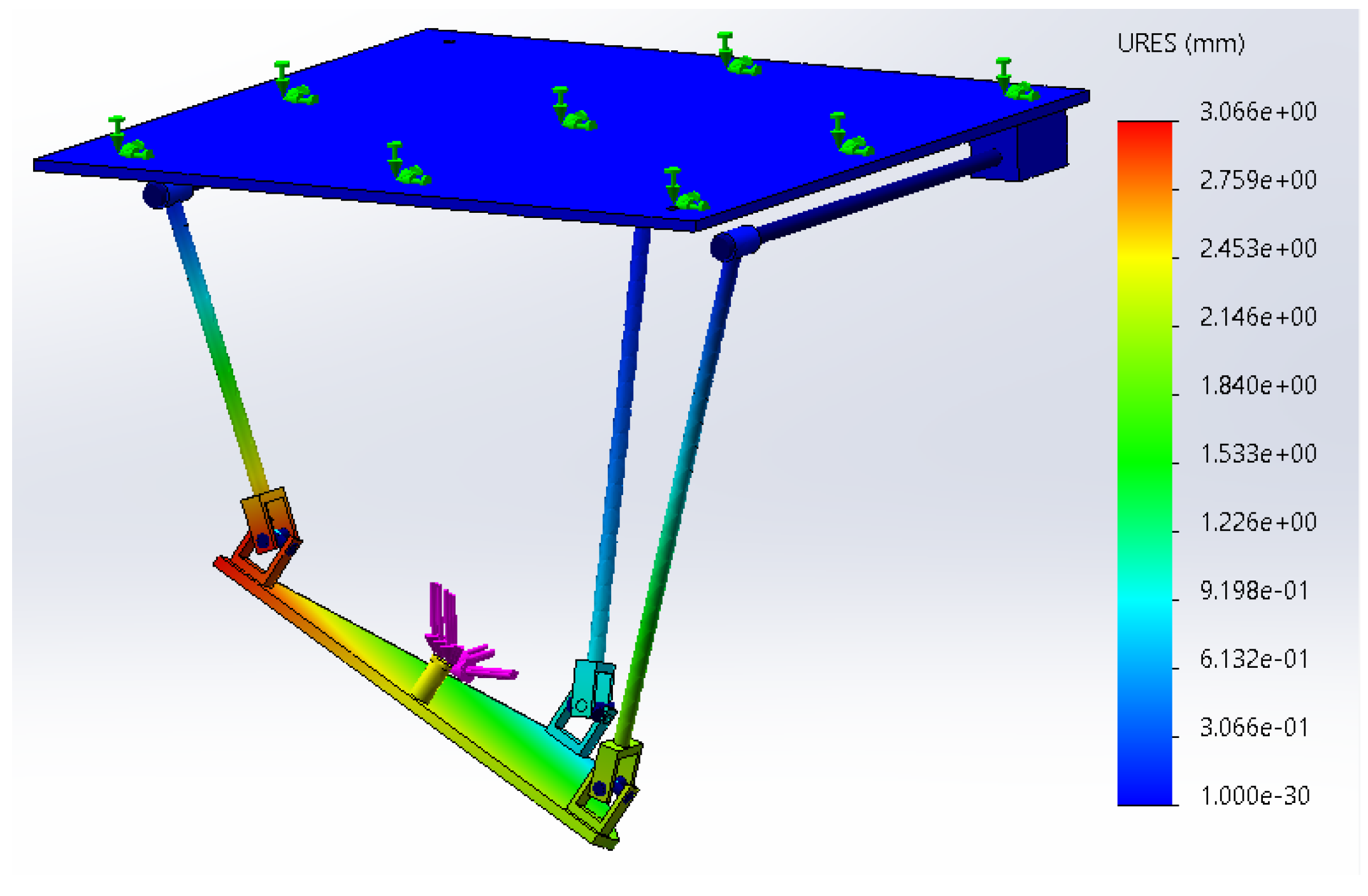
Set Es = 2.1 × 10¹¹ Pa, I = π × (0.03)4/64 m4, S = π × (0.015)2 m2, G = 8 × 10¹⁰ Pa, and Ic = π × (0.03)4/32 m4. Set the pose parameters of the m of the PM as α = 20°, β = −30°, x= 1 m, y= 0.3 m, and z= 0.8 m, and the applied wrenches are set to F = [30 15 20]T N and T = [0 0 0]T N·m. Combined with Equation (35), the stiffness matrix of the can be solved. In terms of simulation, a finite element model is established based on the specified geometric dimensions and material parameters. When the same external loads as those in the analytical model were applied to the finite element model, the resulting deformation is shown in Figure 5, and the parameters of the model are presented in Table 1. Detailed simulation results are presented in Table 2.
As is well known, the results obtained from a finite element model are influenced by various factors, including material properties, element size and type, appropriate boundary conditions, and connection constraints. Therefore, the solutions provided by the finite element model are inherently approximate. As shown in Table 2, the results obtained from theoretical calculations are generally consistent with those from the finite element model, verifying the correctness of the theoretical model.

4.2. Stiffness Characteristics Analysis

According to the studies in [24], when the employed matrices exhibit inhomogeneous characteristics in terms of dimensionality, inconsistencies arise in the performance indices at the level of physical units. The indices δp, δФ, F, and T possess different properties and dimensions, making it inappropriate to evaluate stiffness performance using a mixed form of F and T. To address the inconsistency in physical units of external loads, this paper separately considers the computation and evaluation of linear and angular stiffness performances based on force (F) and torque (T), respectively.
From Equation (35), it can be seen that the relationship between the external load and the corresponding deformation is the following:
δ p δ Φ = C F T , C = C p F C p T C Φ F C Φ T , C = K 1
where C is the compliance matrix. To evaluate the positional deformation caused by F, it is assumed that the load applied to m is a unit pure force FI. Let δpF and δФF denote the corresponding linear and angular deformations caused by the FI, respectively. From Equation (36), we obtain the following:
δ p F = C pF F I , δ Φ F = C Φ F F I
To evaluate the positional deformation caused by T, it is assumed that the load applied to the moving platform is a unit pure force TI. Let δpT and δФT denote the corresponding linear and angular deformations caused by TI, respectively. From Equation (36), we obtain the following:
δ p T = C pT T I , δ Φ T = C Φ T T I
By formulating Lagrange equations based on the equalities in Equations (37) and (38), the maximum and minimum deformations of m caused by the corresponding pure unit force or pure unit moment can be obtained. Then, the maximum and minimum δpF of this PM can be described as follows [5]:
δ p F max = λ p F max ,     δ p F min = λ p F min
where λpFmax and λpFmin are the maximum and minimum eigenvalues of C p F T C p F , respectively.
By using the same method, the maximum and minimum of δФF can be described as follows:
δ Φ F max = λ Φ F max ,     δ Φ F min = λ Φ F min
where λФFmax and λФFmin are the maximum and minimum eigenvalues of C Ф F T C Ф F , respectively.
The maximum and minimum of δpT can be derived as follows:
δ p T max = λ p T max ,     δ p T min = λ p T min
where λpTmax and λpTmin are the maximum and minimum eigenvalues of C p T T C p T , respectively.
The maximum and minimum of δФT can be derived as follows:
δ Φ T max = λ Φ T max ,     δ Φ T min = λ Φ T min
where λФTmax and λФTmin are the maximum and minimum eigenvalues of C Ф T T C Ф T , respectively.
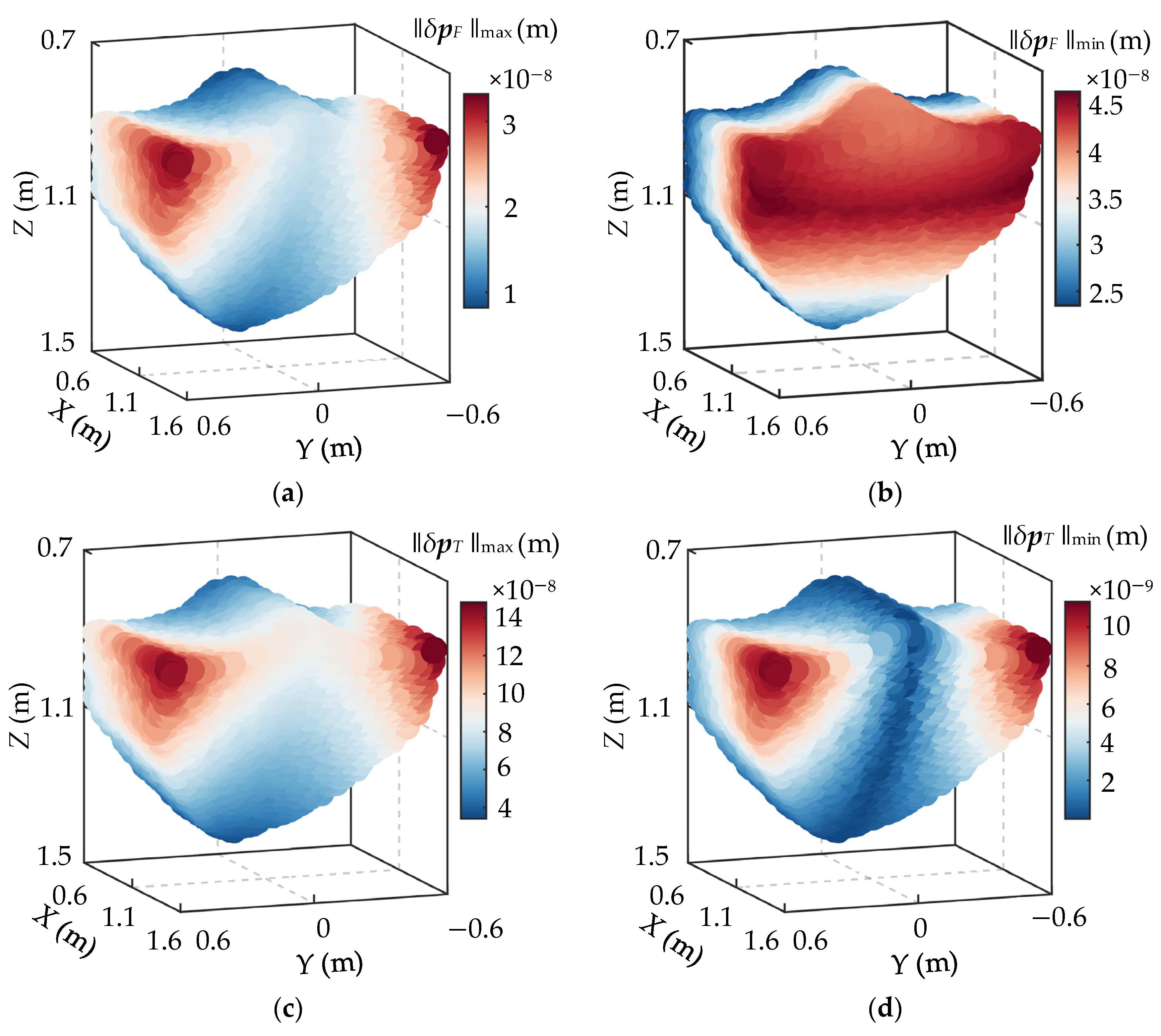
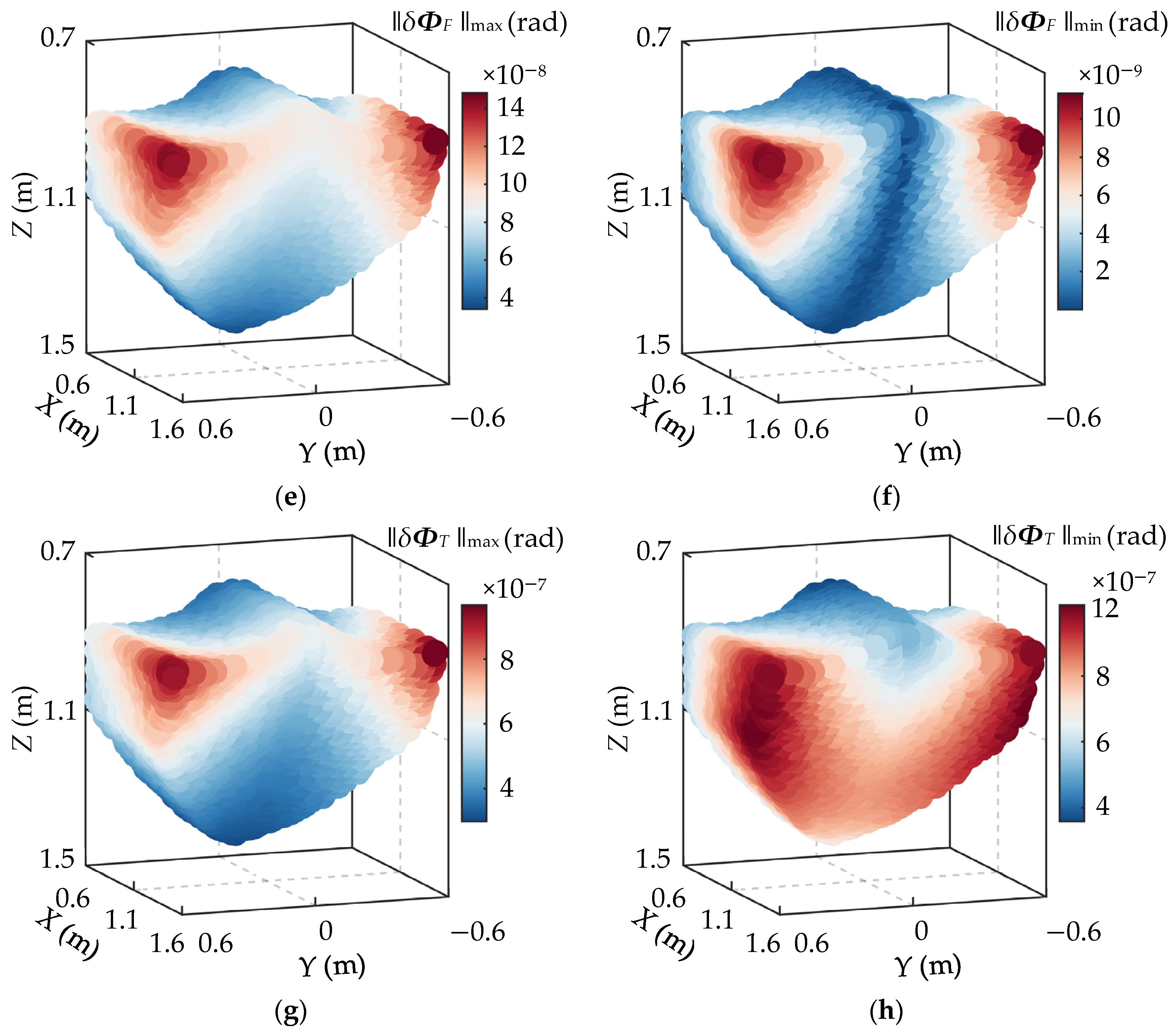
Based on kinematic models, ∥δpFmax, ∥δpFmin, ∥δpTmax, ∥δpTmin, ∥δΦFmax, ∥δΦFmin, ∥δΦTmax, and ∥δΦTmin at each uniformly distributed point in the workspace can be calculated. The distributions of the maximum and minimum deformations of this PM within the workspace are shown in Figure 6.
As shown in Figure 6, the stiffness performance indices of the mechanism are symmetrically distributed with respect to the Y = 0 plane. The distribution patterns of ∥δpFmax, ∥δpTmax, ∥δΦFmax, and ∥δΦTmax within the workspace are consistent: the values are relatively low across most regions, with the maximum occurring in the upper area along the positive X-axis direction. The minimum values of ∥δpTmin and ∥δΦFmin appear near the Y = 0 plane, while their maxima are also located in the upper region along the positive X-axis. ∥δpFmin and ∥δpTmin increase gradually with increasing X values, reaching their maxima at the far end of the positive X-axis.
As shown in Figure 6, the motion height of the moving platform and external loads have a significant influence on the stiffness distribution of the parallel mechanism. Therefore, the operational workspace of the mechanism should preferably be selected near the central region of the mechanism’s working envelope. For typical external loading scenarios, the operational range during machining should be carefully determined based on the stiffness performance distribution. In particular, low-stiffness regions should be avoided through the use of appropriate trajectory planning.
Based on the introduction of the structural topology, kinematic workspace, transmission performance and stiffness performance of the aforementioned new dual-drive parallel mechanism, its advantages and disadvantages are summarized in Table 3.

5. Conclusions

This paper presents a kinematic and stiffness study of a novel symmetric 5-DOF PM with P(2PRPU)/PRPS configuration.
A position model of the 5-DOF P(2PRPU)/PRPS PM was established, and the workspace was obtained through inverse kinematic analysis. A 5 × 5 Jacobian matrix was derived to describe the mapping between the independent motion parameters of the end-effector and the actuator velocities. Moreover, the pressure angle was adopted as an index to evaluate the transmission performance of the mechanism. The results show that the workspace of the mechanism approximates a quarter of a solid sphere, where the central initial region exhibits superior kinematic performance, while the performance degrades toward the boundaries along the X and Y directions.
A stiffness model of the mechanism considering the action of constraint torques was established, and the stiffness and flexibility matrices of the mechanism were derived. To validate the model, a comparative analysis was conducted using finite element simulation, yielding results that showed good agreement. Based on the stiffness model, performance evaluation indices were further proposed, and the stiffness distribution characteristics throughout the entire workspace were analyzed. The evaluation results indicate that the mechanism demonstrates excellent stiffness performance across most of the workspace.
Future research will focus on size optimization to further facilitate the practical application of the proposed 5-DOF PM in engineering.

Author Contributions

Conceptualization, X.Z.; methodology, X.Z.; validation, X.Z.; investigation, X.R.; resources, X.R.; writing—original draft preparation, X.Z.; writing—review and editing, X.Z.; visualization, X.R.; supervision, X.R. All authors have read and agreed to the published version of the manuscript.

Funding

This research was funded by the Scientific research project of colleges and universities in Hebei Province (No. QN2025199) and the Scientific research Fund of Hebei Normal University of Science and Technology (No. 2025YB039).

Data Availability Statement

Data are contained within the article.

Conflicts of Interest

The authors declare no conflicts of interest.

Abbreviations

The following abbreviations are used in this manuscript:
PMparallel mechanism
DOFdegree of freedom

References

  1. Wang, R.Y.; Niu, Z.L.; Chen, K.X.; Sun, T. Kinematic optimization design and performance simulation of novel 5-DOF parallel machining robots with spatial layout. Machines 2022, 10, 1187. [Google Scholar] [CrossRef]
  2. Dasgupta, B.; Mruthyunjaya, T.S. The Stewart platform manipulator: A review. Mech. Mach. Theory 2000, 35, 15–40. [Google Scholar] [CrossRef]
  3. Wu, J.; Wang, L.P.; Guan, L.W. A study on the effect of structure parameters on the dynamic characteristics of a PRRRP parallel manipulator. Nonlinear Dyn. 2013, 74, 227–235. [Google Scholar] [CrossRef]
  4. Dong, C.L.; Liu, H.T.; Huang, T.; Chetwynd, D.G. A screw theory-based semi-analytical approach for elastodynamics of the tricept robot. ASME. J. Mech. Robot. 2019, 11, 031005. [Google Scholar] [CrossRef]
  5. Hu, B. Kinematically identical manipulators for the Exechon parallel manipulator and their comparison study. Mech. Mach. Theory 2016, 103, 117–137. [Google Scholar] [CrossRef]
  6. Wang, Z.L.; Zhang, N.B.; Chai, X.X.; Li, Q.C. Kinematic/dynamic analysis and optimization of a 2-URR-RRU parallel manipulator. Nonlinear Dyn. 2017, 88, 503–519. [Google Scholar] [CrossRef]
  7. Ye, W.; Fang, Y.F.; Guo, S.; Qu, H.B. Type synthesis of 2R2T parallel mechanisms based on motion equivalent chain method. Proc. Inst. Mech. Eng. Part C 2014, 228, 3209–3217. [Google Scholar] [CrossRef]
  8. Ye, W.; He, L.Y.; Li, Q.C. A new family of symmetrical 2T2R parallel mechanisms without parasitic motion. ASME. J. Mech. Robot. 2018, 10, 011006. [Google Scholar] [CrossRef]
  9. Xie, F.G.; Liu, X.J.; Luo, X.; Wabner, M. Mobility, singularity, and kinematics analyses of a novel spatial parallel mechanism. ASME. J. Mech. Robot. 2016, 8, 061022. [Google Scholar] [CrossRef]
  10. Xie, Z.H.; Xie, F.G.; Liu, X.J.; Wang, J.S.; Mei, B. Tracking error prediction informed motion control of a parallel machine tool for high-performance machining. Int. J. Mach. Tools Manuf. 2021, 164, 103714. [Google Scholar] [CrossRef]
  11. Tunc, L.T.; Shaw, J. Experimental study on investigation of dynamics of hexapod robot for mobile machining. Int. J. Adv. Manuf. Technol. 2016, 84, 817–830. [Google Scholar] [CrossRef]
  12. Chen, K.X.; Wang, M.; Huo, X.M.; Wang, P.F.; Sun, T. Topology and dimension synchronous optimization design of 5-DoF parallel robots for in-situ machining of large-scale steel components. Mech. Mach. Theory 2023, 179, 105105. [Google Scholar] [CrossRef]
  13. Zhang, X.C.; Rong, Y.; Wang, H.B.; Zhang, S.J. Kinematics and Dynamics Analysis of a New 5-Degrees of Freedom Parallel Mechanism with Two Double-Driven Chains. Machines 2025, 13, 419. [Google Scholar] [CrossRef]
  14. Li, L.Q.; Fang, Y.F.; Guo, S.; Qu, H.B.; Wang, L. Type synthesis of a class of novel 3-DOF single-loop parallel leg mechanisms for walking robots. Mech. Mach. Theory 2020, 145, 103695. [Google Scholar] [CrossRef]
  15. Li, W.; Angeles, J. The design of a 3-CPS parallel robot for maximum dexterity. Mech. Mach. Theory 2018, 122, 279–291. [Google Scholar] [CrossRef]
  16. Wu, M.L.; Li, D.Z.; Cao, Y.R.; Wang, X.H.; Jia, L.D. Dynamic analysis and impedance control of a novel double-driven parallel mechanism. J. Intell. Robot. Syst. 2023, 108, 45. [Google Scholar] [CrossRef]
  17. Lu, Y.; Wang, P.; Zhao, S.H.; Hu, B.; Han, J.D.; Sui, C.P. Kinematics and statics analysis of a novel 5-DoF parallel manipulator with two composite rotational/linear active legs. Robot. Comput. Integr. Manuf. 2014, 30, 25–33. [Google Scholar] [CrossRef]
  18. Rong, Y.; Zhang, X.C.; Dou, T.C.; Wang, H. Type synthesis of non-overconstrained and overconstrained two rotation and three translation (2R3T) parallel mechanisms with three branched chains. Mech. Sci. 2023, 14, 567–577. [Google Scholar] [CrossRef]
  19. Ye, N.J.; Hu, B. Kinematic and Stiffness Modeling of a Novel 3-DOF RPU+UPU+SPU Parallel Manipulator. IEEE Access 2021, 10, 6304–6318. [Google Scholar] [CrossRef]
  20. Ma, X.J.; Xu, Z.H.; Xu, Y.D.; Wang, Y.; Yao, J.T.; Zhao, Y.S. Evaluation on configuration stiffness of overconstrained 2R1T parallel mechanisms. Chin. J. Mech. Eng. 2024, 37, 62. [Google Scholar] [CrossRef]
  21. Ye, N.J.; Hu, B. Stiffness modeling of some 4-DOF over-constrained parallel manipulators with various constrained wrench forms. Mech. Mach. Theory 2022, 172, 104821. [Google Scholar] [CrossRef]
  22. Xue, Y.; Qu, H.B.; Li, X.; Guo, S. Stiffness performance analysis of a 3-PRPS kinematically redundant parallel mechanism. Proc. Inst. Mech. Eng. Part C J. Mech. Eng. Sci. 2023, 237, 589–602. [Google Scholar] [CrossRef]
  23. Raoofian, A.; Taghvaeipour, A.; Kamali, A. On the stiffness analysis of robotic manipulators and calculation of stiffness indices. Mech. Mach. Theory 2018, 130, 382–402. [Google Scholar] [CrossRef]
  24. Li, Y.M.; Xu, Q.S. Stiffness analysis for a 3-PUU parallel kinematic machine. Mech. Mach. Theory 2008, 43, 186–200. [Google Scholar] [CrossRef]
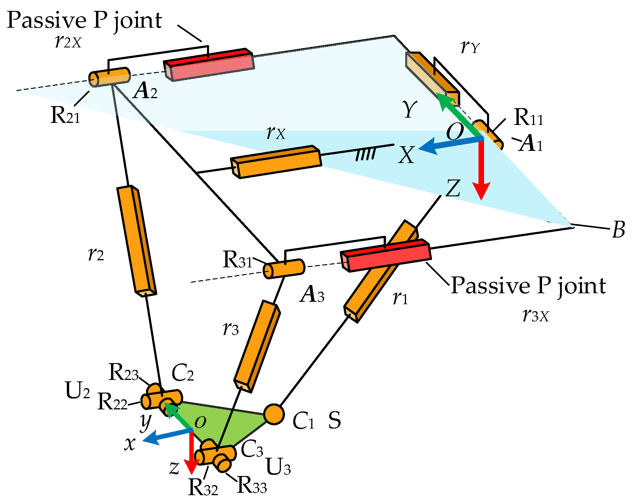
Figure 1. Sketch of P(2PRPU)/PRPS PM.
Electronics 14 03400 g001
Figure 2. Motion schematic of the P(2PRPU)/PRPS PM: (a) the moving platform rotates around the X-axis; (b) the moving platform rotates around the y-axis; (c) the moving platform moves along the X-axis (α = 0, β = 0); (d) the moving platform moves along the y-axis (α = 0, β = 0).
Electronics 14 03400 g002
Figure 3. Workspace of the P(2PRPU)/PRPS PM (α = 0, β = 0): (a) discrete point cloud; (b) solid.
Electronics 14 03400 g003
Figure 4. The distribution of transmission performance index in the workspace (α = 0, β = 0): (a) μ1; (b) μ2; (c) μ3; (d) μ.
Electronics 14 03400 g004aElectronics 14 03400 g004b
Figure 5. The elastic deformations of the FE model.
Electronics 14 03400 g005
Figure 6. The distribution of stiffness index in the workspace: (a) ∥δpFmax; (b) ∥δpFmin; (c) ∥δpTmax; (d) ∥δpTmin; (e) ∥δΦFmax; (f) ∥δΦFmin; (g) ∥δΦTmax; (h) ∥δΦTmin.
Electronics 14 03400 g006aElectronics 14 03400 g006b
Table 1. Material property table of the FE model.
Material PropertyNumeric Value
Elastic modulus211 GPa
Poisson’s ratio0.28
Density7800 kg/m3
Yield strength220 MPa
Ultimate tensile strength400 MPa
Table 2. The comparison of the elastic deformation of m derived from the analytical approach and FE model.
Elastic Deformation of mδx (m)δy (m)δz (m)
FE model results0.5989 × 10−32.3500 × 10−30.1673 × 10−3
Analytics results0.5920 × 10−32.4537 × 10−30.1568 × 10−3
Error1.2%4.4%6.3%
Table 3. Advantages and disadvantages of the P(2PRPU)/PRPS PM.
AdvantagesDisadvantages
The dual-drive configuration makes the structure compactThe theoretical analysis is complex
Good stiffness performanceThe workspace is not entirely symmetrical
Good transmission performanceComplex control
The inertia coupling is relatively smallHigh manufacturing cost
Disclaimer/Publisher’s Note: The statements, opinions and data contained in all publications are solely those of the individual author(s) and contributor(s) and not of MDPI and/or the editor(s). MDPI and/or the editor(s) disclaim responsibility for any injury to people or property resulting from any ideas, methods, instructions or products referred to in the content.