1. Introduction
Reliable partial discharge (PD) detection is crucial to maintaining the health of high-voltage equipment such as transformers, cables, and generators. According to IEC 60270, PD is localized discharge that partially bridges the insulation between conductors, often occurring near conductors [
1]. PD is a small discharge phenomenon occurring in insulating materials. With the development of PD, the discharge intensity will gradually increase. At the same time, it will lead to the further deterioration of the insulating material [
2,
3]. In severe cases, it will cause insulation breakdown [
4,
5]. PD measurement is a vital tool for monitoring the condition of high-voltage equipment, preventing damage, and ensuring system reliability [
6].
There are several methods to detect PD, such as direct voltage, Dissolved Gas Analysis (DGA), high frequency (HF), Transient Earth Voltage (TEV), ultra-high frequency (UHF), Rogowski coils, epoxy-mica capacitors, Radio Frequency (RF), and optical methods [
7,
8,
9,
10,
11,
12,
13]. Nowadays, high-frequency current transformers (HFCTs) are often recommended for measuring PD [
6,
14]. HFCTs’ sensitivity, wide frequency range, portability, and suitability for online monitoring are advantages of HFCTs compared with other sensors [
15,
16,
17,
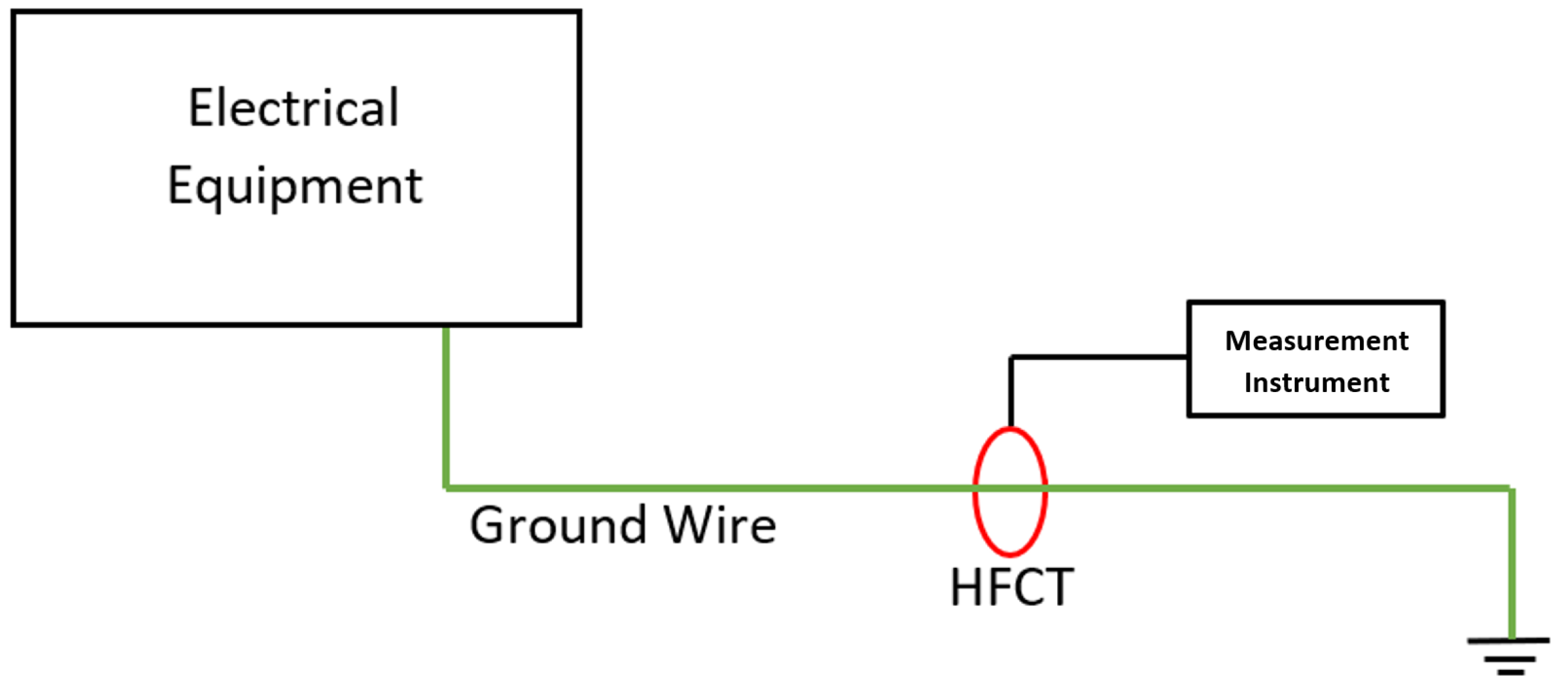
18]. Online PD measurements have become a common practice for assessing the insulation condition of installed HV equipment. For utilities, the most interesting advantage of online PD measurements is that once the sensors are installed in the power grid, the electrical service is not interrupted for the measurements. In general, when online PD measurements are performed on HV installations, HFCT sensors are clamped in the grounding conductors of the earthing network [
6,
19,
20,
21]. The installation of HFCTs is shown in
Figure 1.
HFCTs are specialized devices used to detect and measure high-frequency transient currents [
8]. HFCT sensors are widely used for PD detection, and their application for the location and identification of PD sources is very effective. Like current transformers in general, they work based on Ampere’s Law and Faraday’s Law [
22]. HFCTs are widely used inductive couplers as non-intrusive measurement devices converting time-varying current into a voltage signal scaled by the number of turns in the transformer [
23].
While various methods, such as DGA and TEV, are available for partial discharge (PD) detection, HFCTs are uniquely suited for non-intrusive, real-time monitoring [
14,
24]. Compared with other unconventional methods, HFCT sensors have some attractive advantages, such as galvanic isolation to test subjects, low price, reasonable sensitivity, and wide bandwidth, which make them suitable for PD detection. Also, they can measure PD in high-voltage equipment such as power transformers, high-voltage cables, and gas-insulated switchgear (GIS) [
25,
26]. However, during online PD measurements, HFCT cores are often exposed to magnetic fields generated by 50–60 Hz currents. These low-frequency currents induce additional magnetic fields, which can exacerbate core saturation in the HFCT.
Core saturation is a critical issue that significantly affects the performance of HFCTs [
27]. As the core saturates, its ability to accurately detect high-frequency signals becomes compromised. When the magnetic flux within the core reaches saturation, the core’s magnetic response becomes non-linear, leading to a distortion in the sensor’s output [
19]. This saturation effect limits the dynamic range of the HFCT, reducing its ability to detect high-frequency components, such as those generated by partial discharge (PD) activity. As a result, in the presence of large low-frequency components, the HFCT becomes unable to capture high-frequency PD signals, making accurate PD detection difficult.
To avoid core saturation in HFCTs due to low-frequency currents and ensure output linearity, several studies have been conducted. Researchers have introduced air gaps between the magnetic cores [
28,
29,
30,
31,
32]. Although air gaps are effective in preventing core saturation, they also significantly reduce HFCT sensitivity—a critical limitation for PD measurement applications [
33,
34]. Introducing an air gap increases magnetic circuit reluctance due to the low permeability of air. Nevertheless, the fringing effect at the gap boundaries expands the effective flux path area, partially mitigating this increase in reluctance. The fringing effect, which occurs at the boundaries of the air gap, can be considered approximately half-circular when the flux flows between two cores separated by the air gap [
35]. The analytical estimate of fringing flux permeance (
) can be written as follows:
where
is the fringing flux permeance (
H),
is the air gap permeance (
),
L is the stacking length (
m),
X is the outer diameter of the fringing flux (
m), and
g is the air gap length (
m). To address the issue of reduced sensitivity in HFCTs, other researchers proposed using frequency-dependent impedance connected to the HFCT output [
33,
34]. This approach reduces the magnetic field inside the ferrite core, thereby counteracting saturation. However, in 2022, Fritsch and Wolter conducted similar experiments and explained that frequency-dependent impedance acts like a high-pass filter rather than directly reducing the magnetic field within the ferrite core [
25]. While this method minimizes the effects of saturation to a tolerable level without impacting high-frequency sensitivity, it does not eliminate core saturation. Consequently, HFCT sensitivity is still compromised. Both methods thus lead to a loss of HFCT sensitivity. A new approach is needed to maintain HFCT sensitivity while preventing core saturation in high-current environments.
This study aims to enhance the sensitivity of HFCTs while simultaneously increasing their saturation capability. To achieve this, we thoroughly investigate the effects of HFCT saturation caused by 60 Hz currents ranging from 2 A to 2000 A when an air gap is applied to the core. Additionally, we propose a novel air gap design intended to improve the sensitivity of the HFCT without compromising its performance under high-current conditions. Further details of our methodology, including the design of the new air gap will be elaborated in the HFCTs and Simulations Design Section. This comprehensive approach ensures a robust evaluation of the proposed solutions and their potential impact on HFCT performance.
In practical terms, enhancing the sensitivity of HFCTs is crucial to improving the accuracy and reliability of partial discharge (PD) detection in high-voltage equipment. Higher sensitivity allows the HFCT to detect weaker PD signals that might otherwise go unnoticed, especially in environments with strong low-frequency interference, such as 50–60 Hz leakage currents. This increased capability supports earlier fault detection and predictive maintenance, which are essential to avoiding catastrophic insulation failures.
Although previous studies have introduced air gaps to mitigate core saturation, most have focused exclusively on symmetrical configurations. To the best of our knowledge, a detailed evaluation of asymmetrical air gap structures and their direct influence on flux behavior and HFCT sensitivity has not been thoroughly explored in the existing literature. This study addresses that gap by proposing and analyzing an asymmetrical design, demonstrating how geometric asymmetry can offer superior flux concentration and improved sensor performance compared with conventional methods.
Therefore, the proposed asymmetrical air gap design, which improves sensitivity by increasing magnetic flux density, has a direct and positive impact on the HFCT performance in real-world PD monitoring applications.
2. HFCTs and Simulation Design
The construction of an HFCT is simple and is essentially based on a magnetic core and a secondary copper winding with N turns wound around its core. HFCTs are usually achieved on a closed magnetic core where the single-turn primary winding is the cable through which the measuring current flows and the secondary winding is a distributed winding [
33].
An HFCT consists mainly of a toroidal core and a secondary winding around this core [
23,
28,
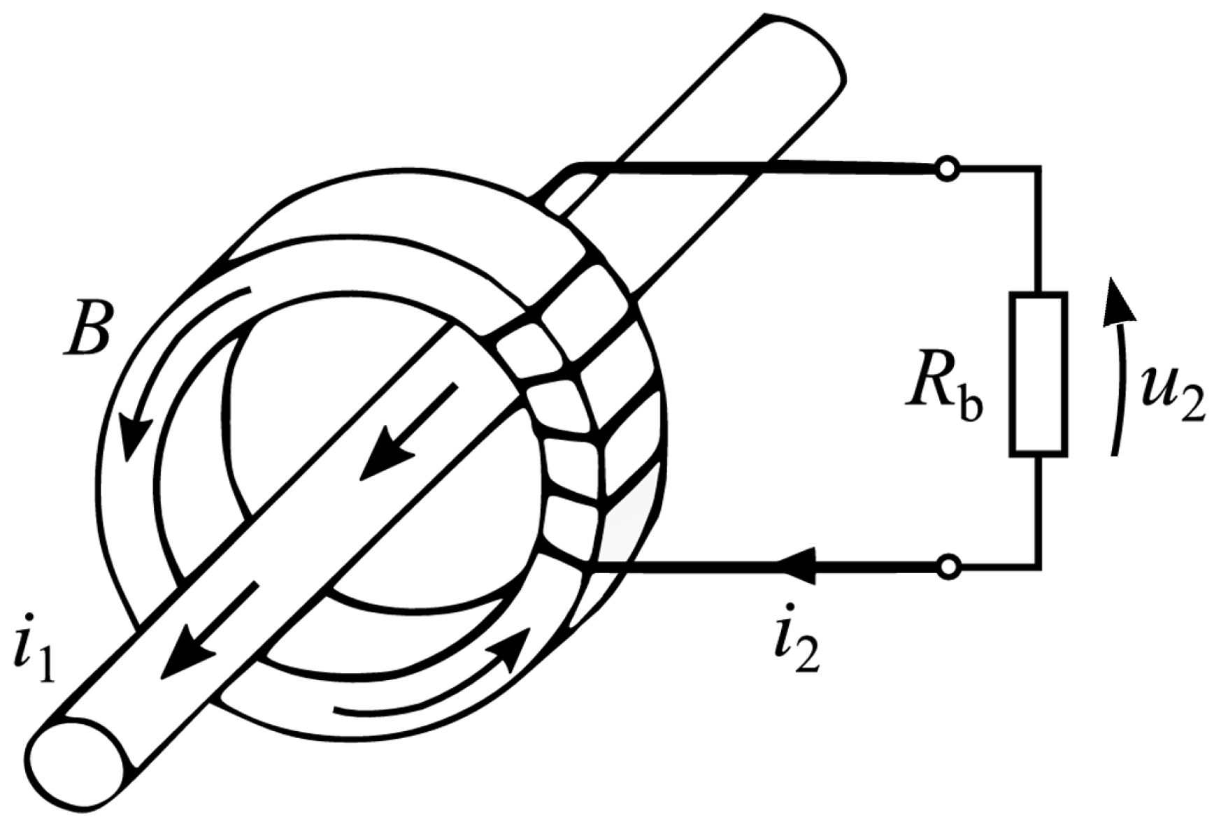
36]. Soft ferrite cores, such as manganese–zinc (MnZn) and nickel–zinc (NiZn), are effective couplers between electric current and magnetic flux. The structure and operating principle of such a sensor is shown schematically in
Figure 2.
Figure 2 illustrates the operating principle of an HFCT, used for detecting high-frequency components of current such as partial discharges. The current (
) flowing through the primary conductor generates a magnetic field (
B), which is concentrated in the toroidal magnetic core surrounding the conductor.
According to Faraday’s Law of Induction, a time-varying magnetic flux () through the core induces an electromotive force in the secondary winding. This results in an induced current (), which flows through the burden resistor (), creating a measurable output voltage ().
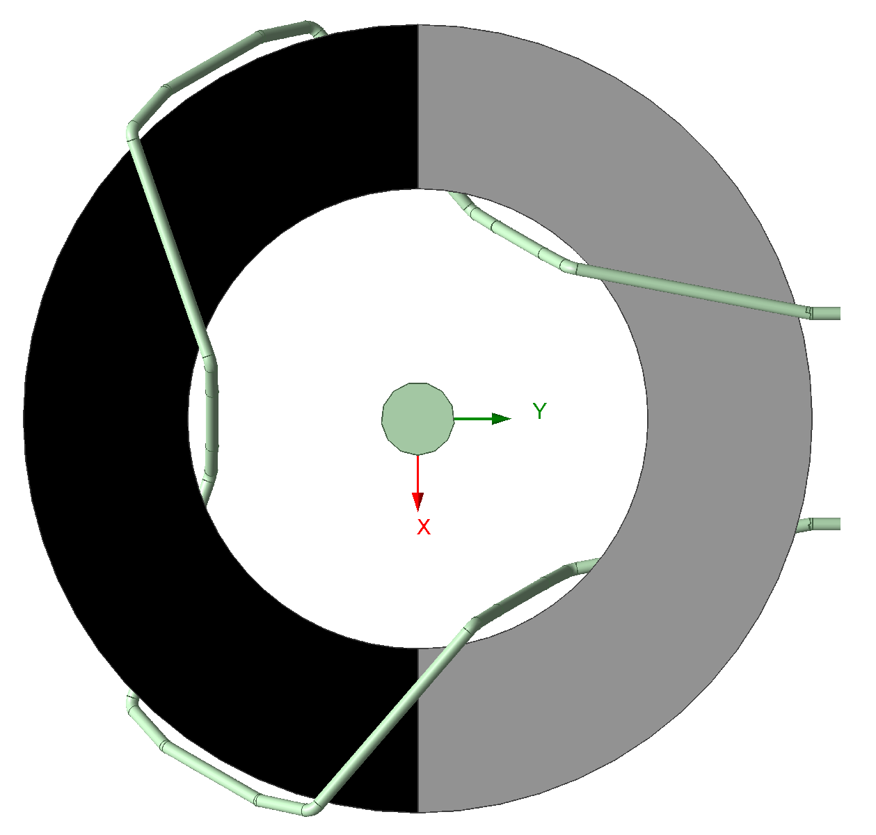
2.1. HFCT Design
In the design of the HFCT used in this study, a secondary winding with 3 turns was chosen to optimize signal sensitivity. A lower number of turns increases sensitivity, enhancing the HFCT’s ability to detect small changes in high-frequency currents [
3]. This 3-turn secondary winding further supports the goal of improving the HFCT’s overall sensitivity. The low-turn ratio reduces voltage drops across the winding, minimizing power losses and ensuring accurate signal capture. Consequently, this configuration enables the HFCT to reliably detect high-frequency partial discharge signals, which is critical to real-time, non-intrusive monitoring in high-voltage applications.
Figure 3 illustrates the HFCT design as modeled in the simulation, providing a clear view of the core structure and configuration.
To ensure that the HFCT operates in CT mode rather than VT mode, the secondary winding was modeled with a burden resistor of 50 to replicate typical load conditions in practical HFCT applications. This condition ensures that the current induced in the secondary winding produces a counteracting magnetomotive force (MMF) that stabilizes the core flux, thereby preventing premature saturation.
2.2. Simulation Design
The simulations were performed using Ansys Electronics Desktop 2023 R1, specifically employing the Maxwell 3D environment. To analyze the magnetic behavior of the HFCT cores under various air gap configurations, the Eddy Current solver was primarily used. This solver is particularly well-suited for frequency-domain simulations involving low-frequency excitation (e.g., 60 Hz), making it ideal for modeling magnetic flux behavior and evaluating the effects of core material properties, geometry, and air gap structures.
In addition, Maxwell 3D also supports Transient simulations, which are commonly used to examine time-varying electromagnetic fields. Although the present study focuses on steady-state performance, the solver’s capability to capture dynamic effects ensures a comprehensive understanding of saturation phenomena and flux distributions.
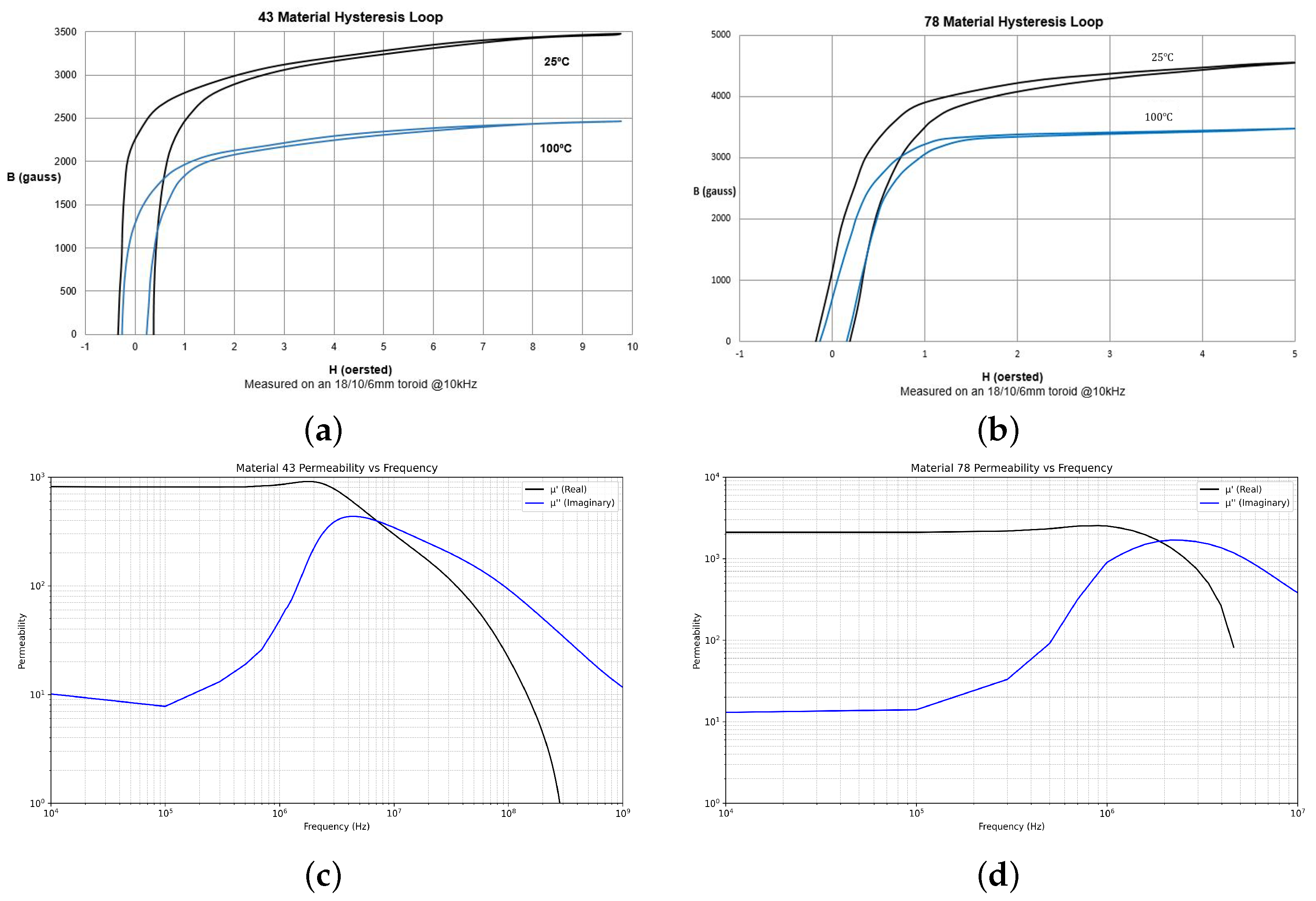
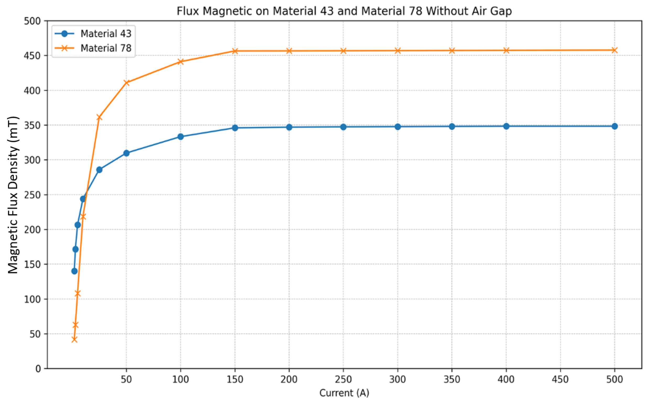
In this research study, two specific ferrite materials—Material 43 and Material 78 from Fair-Rite, Wallkill, NY, USA in toroidal form—were chosen for their unique magnetic properties, including initial relative permeability, frequency range, and saturation flux density. The material properties of both ferrites are illustrated in
Figure 4.
Material 43 has an initial relative permeability of 850, a frequency range of up to 10 MHz, and a saturation flux density of 0.35 Tesla [
37]. It is optimized for higher-frequency applications where lower saturation levels are acceptable. In contrast, Material 78 has a higher initial relative permeability of 2300, a frequency range of up to 200 kHz, and a saturation flux density of 0.45 Tesla [
38]. This makes it suitable for applications prioritizing stronger magnetic coupling but with increased susceptibility to saturation at lower frequencies. This susceptibility arises because the higher initial permeability (
) of Material 78 leads to a steeper slope in its B-H curve near the origin. As a result, even relatively small magnetizing field strength (
H) induces proportionally large magnetic flux density (
B). The dimensions of both ferrite cores are shown in
Table 1.
To assess the impact of air gap configurations on the performance of the HFCT, simulations were conducted using Ansys Electronics Desktop. The model was discretized using 276,200 tetrahedral mesh elements for Material 43 and 389,686 for Material 78, which provided sufficient resolution to capture the magnetic behavior within the core and surrounding air. The simulation domain was enclosed with a magnetic insulation boundary condition to prevent magnetic field leakage. The mesh quality and refinement were adjusted to ensure convergence and numerical stability. The simulations modeled three core configurations: (1) a core without an air gap, (2) a core with a symmetrical air gap, and (3) a core with an asymmetrical air gap. These configurations were chosen based on the goal of evaluating how different air gap geometries influence the HFCT’s ability to handle varying current loads without saturation. The simulations were carried out in a range of currents 2 A to 2000 A at 60 Hz, which are representative of typical operating conditions of high-voltage equipment. The simulations were designed to compare the magnetic flux distribution, saturation thresholds, and sensitivity of each configuration. For each scenario, the same core material properties, dimensions, and number of turns were used.
2.2.1. Without Air Gap
The initial simulation examines HFCT core performance without any air gap, serving as a control to establish baseline values for sensitivity and saturation resistance. This configuration allows us to observe the core’s natural magnetic response and behavior under varying current loads, ranging from 2 A to 2000 A at 60 Hz.
In this baseline setup, both Material 43 and Material 78 are analyzed independently to observe how their unique magnetic properties influence HFCT performance. These results serve as a benchmark for evaluating the potential improvements introduced by symmetric and asymmetric air gaps in subsequent simulations.
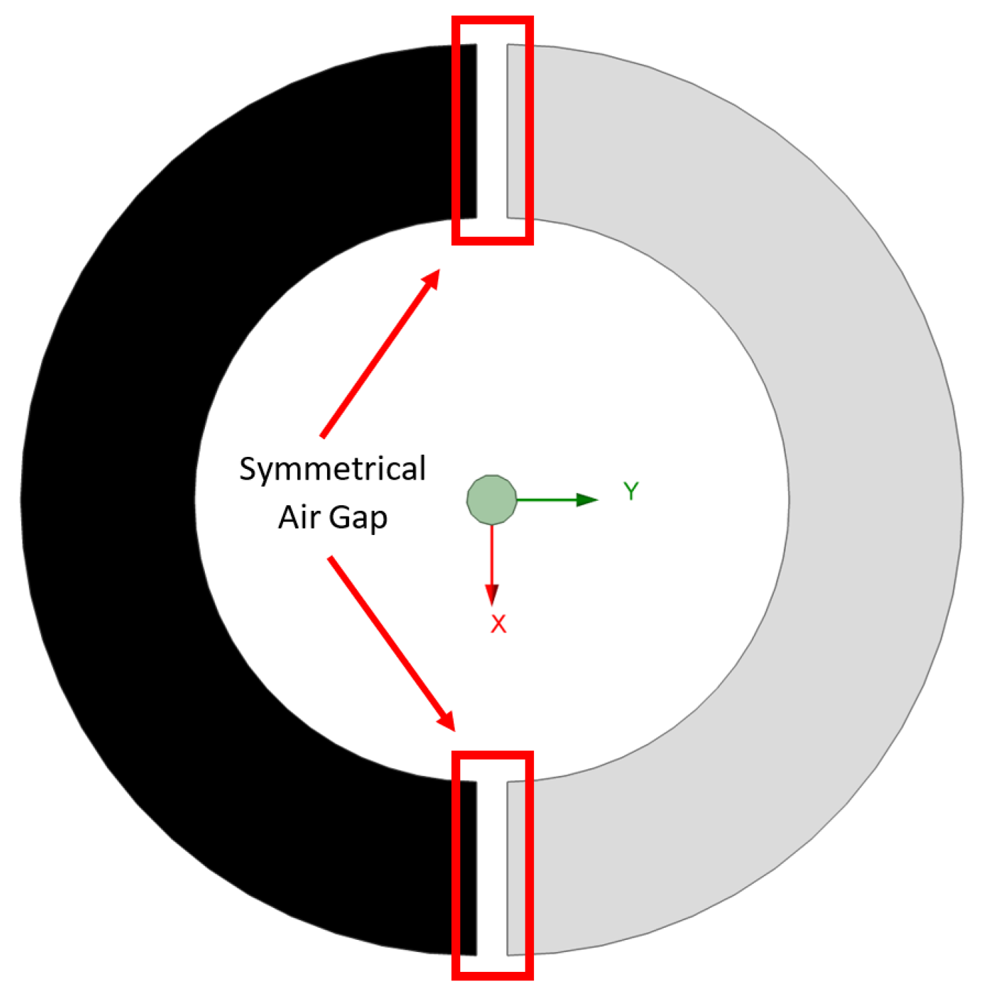
2.2.2. Symmetrical Air Gap
The second simulation introduces a symmetrical air gap into the HFCT core to evaluate its impact on sensitivity and saturation resistance. In this configuration, identical air gaps are placed on opposite sides of the core, creating a balanced magnetic path designed to mitigate core saturation.
Figure 5 illustrates the HFCT design with the symmetrical air gap, showing the placement and size of the gaps as modeled in the simulation.
This simulation was conducted across a range of seven different air gap variations, specifically 0.5 mm, 1 mm, 1.5 mm, 2 mm, 2.5 mm, 3 mm, and 3.5 mm, with current levels ranging from 2 A to 2000 A at 60 Hz. These configurations allow for a direct comparison with the no-air gap configuration and provide insights into the effects of varying air gap sizes on the performance of the HFCT. The symmetrical air gap introduces additional reluctance into the magnetic circuit, which is expected to reduce the likelihood of core saturation by limiting the magnetic flux density within the core. However, this increased reluctance may also reduce the HFCT’s sensitivity, a critical metric analyzed in this setup.
Both Material 43 and Material 78 were used independently in the simulation to observe how the symmetrical air gap affects each material’s performance. The results from this configuration provide valuable insights into whether a balanced air gap placement enhances the HFCT’s saturation resistance without significantly compromising its sensitivity. These findings will be compared with both the no-air gap and asymmetrical air gap configurations to identify the optimal air gap configuration for HFCT applications.
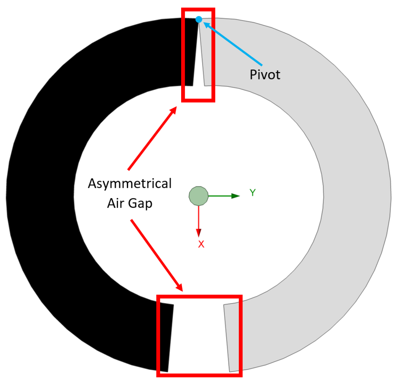
2.2.3. Asymmetrical Air Gap
The third simulation examines the effects of an asymmetrical air gap configuration achieved by angling the two cores, with the apex of the angle positioned at the top of the core. This configuration introduces an unbalanced magnetic path between the cores, leading to a non-uniform distribution of magnetic flux.
Figure 6 presents the HFCT design with this asymmetrical configuration, clearly showing the angular placement of the cores. The primary objective of this simulation is to assess how this angular setup, compared with a symmetrical air gap, influences core saturation and overall sensitivity.
In this simulation, we explore 10 variations in the angular configuration, with the angle between the cores ranging from 1 degree to 10 degrees. The current range for the simulation spans from 2 A to 2000 A at 60 Hz, consistent with the previous configurations, to allow for a direct comparison of the results. The asymmetrical angle increases the reluctance in certain parts of the magnetic circuit, which is expected to provide partial relief from core saturation while maintaining higher sensitivity than a fully symmetrical configuration.
Both Material 43 and Material 78 are independently analyzed to understand how each material responds to the altered magnetic path created by the angled core configuration. The results will be compared with those from the no-air gap and symmetrical air gap configurations to assess whether the angular design offers an optimal balance between sensitivity and saturation resistance. This analysis could present a viable design strategy for enhancing the performance of HFCTs in high-voltage applications.
3. Data Analysis
To thoroughly assess the effects of different air gap configurations on HFCT performance, several key metrics were analyzed from the simulation data. These include magnetic flux density, sensitivity, and core saturation threshold. Each metric provides insights into the effectiveness of the air gap design, allowing for a comprehensive evaluation of HFCT performance across the no-air gap, symmetrical air gap, and asymmetrical air gap configurations.
3.1. Sensitivity Analysis
Sensitivity plays a crucial role in the performance of HFCTs, especially for partial discharge (PD) detection. Sensitivity analysis was performed to evaluate how various air gap configurations affect the HFCT’s ability to detect high-frequency signals. Sensitivity is defined as the ratio of the output voltage (
) to the rate of change in the primary current (
) [
39]. Sensitivity can be calculated using Equation (2):
where
is the induced voltage, as explained by Faraday’s Law of Induction [
21,
40], as shown in Equation (3).
where
N is the number of turns in the secondary winding and
L is the inductance of the secondary winding. The expression for sensitivity
S becomes
The inductance
L can be determined based on the core and winding properties using Equation (5):
where
A is the cross-sectional area of the magnetic path in the core and
l is the mean magnetic path length. By substituting Equation (5) into Equation (4), the final expression for the sensitivity
S becomes
In this study, all HFCT designs are assumed to use the same core material, number of turns, physical dimensions, and are exposed to the same primary current. Consequently, the parameters
A,
N, and
l remain constant across all configurations. Although the material remains the same, the overall permeability (
) differs due to the fringing effect caused by the introduction of various air gap structures. As shown in Equation (6), when all other parameters are fixed, the sensitivity (
S) is ultimately governed by the overall permeability
. According to Equation (7), the magnetic flux density (
B) is directly proportional to the magnetic permeability (
), which is given by
Since the induced voltage in the HFCT is proportional to the rate of change in the flux, it follows that higher flux density leads to greater sensitivity. Therefore, air gap configurations that result in higher magnetic flux also enhance the sensitivity of the HFCT.
However, it is important to note that Equation (7) assumes that the core material is homogeneous, linear, and isotropic. In real-world applications, these ideal conditions are rarely met. Non-linear behavior near saturation, magnetic anisotropy, and the introduction of air gaps significantly affect the flux distribution. As a result, Equation (7) should be regarded as an approximation rather than an exact expression when modeling practical HFCT performance.
3.2. Magnetic Flux Density Analysis
Magnetic flux density was measured throughout the core to observe the distribution of the magnetic field under each air gap configuration. This metric is essential to understanding how the flux is distributed within the core, particularly under high-current conditions. A comparative analysis of flux density distributions across Material 43 and Material 78 cores allows for an assessment of material-specific responses to air gaps.
3.3. Saturation Threshold Determination
The saturation threshold refers to the peak magnetic flux density (B) in the core at which the material enters the non-linear region of its B-H curve, as shown in
Figure 3. This threshold, obtained from the simulation results, indicates each configuration’s susceptibility to magnetic saturation under high-current conditions. By comparing these thresholds, we determine the current levels that initiate saturation in the no-air gap and symmetrical and asymmetrical air gap designs, highlighting their relative performance for high-current applications.
3.4. Comparison Between Symmetrical and Asymmetrical Air Gap
The final analysis aims to compare the sensitivity of symmetrical and asymmetrical air gaps in HFCTs. This comparison will help determine which air gap configuration is more effective in achieving higher sensitivity by analyzing flux magnitude and flux distribution, providing insights into optimal design choices for improved performance. The findings from this evaluation will contribute to the development of improved configurations for high-sensitivity applications in high-voltage equipment monitoring.
4. Results
This section presents the findings from simulations conducted to evaluate the effects of different air gap configurations on the performance of HFCTs. The simulations analyzed three configurations—no air gap, symmetrical air gap, and asymmetrical air gap—across a range of current levels from 2 A to 2000 A at 60 Hz. Key performance metrics, including magnetic flux density, sensitivity, and saturation threshold, were measured to assess the effectiveness of each configuration in enhancing HFCT sensitivity while mitigating core saturation.
The results are organized by configuration type, beginning with the no-air gap baseline, followed by the symmetrical and asymmetrical air gap setups, in Material 43 and Material 78. Each configuration’s impact on HFCT performance is discussed, with comparative analysis highlighting the advantages and trade-offs associated with each design. Visual data representations, including graphs and tables, are included to provide a clear understanding of the trends and differences observed across the simulations.
4.1. No-Air Gap Simulation Result
Figure 7 shows that Material 43 reached magnetic saturation at approximately 350 mT, whereas Material 78 exhibited higher tolerance, saturating at around 450 mT. This difference in saturation flux density is likely attributed to the higher initial permeability and core material characteristics of Material 78. However, both materials converged to their respective saturation points when the input current reached 150 A, indicating a practical operational limit in no-air gap configurations.
These saturation values served as a baseline for evaluating the impact of air gap configurations on HFCT performance. In subsequent simulations, these results will be used as a benchmark to assess how the symmetrical and asymmetrical air gap designs influence saturation resistance and magnetic flux distribution. This comparison will provide insights into the effectiveness of each air gap design in improving HFCT performance while mitigating the saturation challenges observed in the no-air gap configuration.
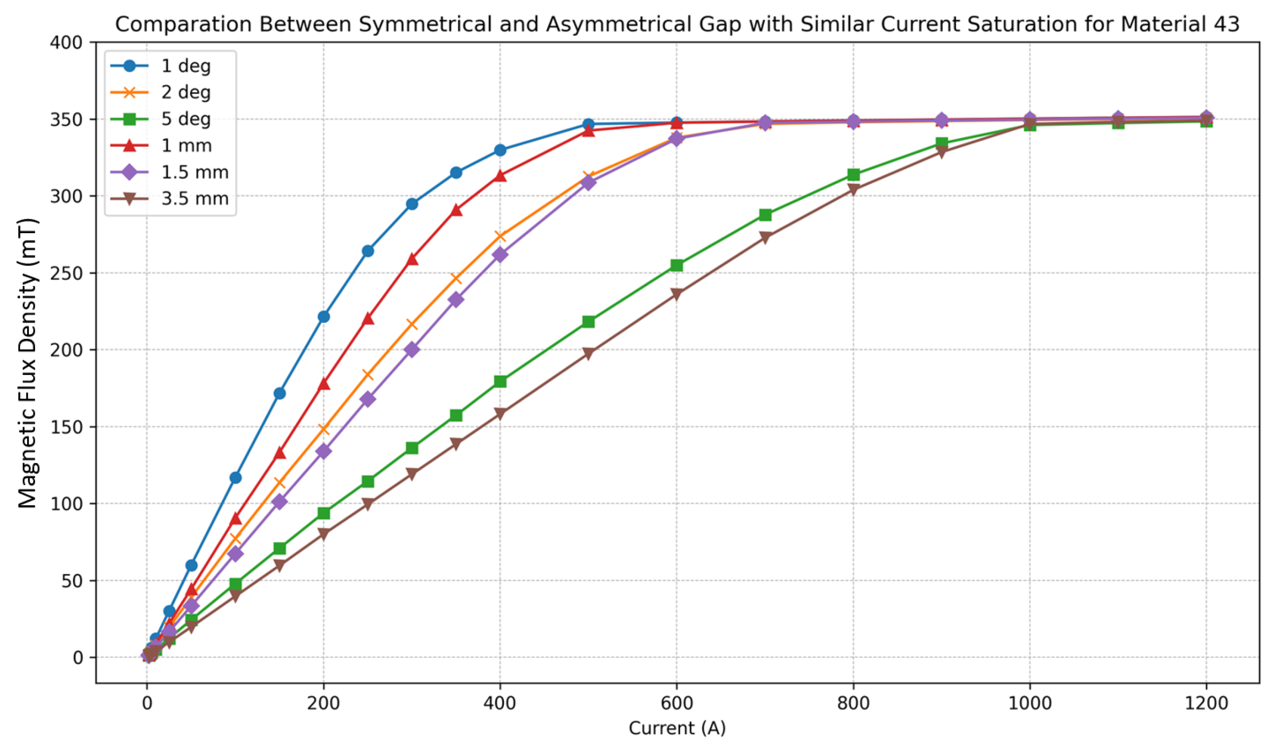
4.2. Material 43 Simulation Results
The simulation evaluated the performance of Material 43 under both symmetrical and asymmetrical air gap configurations. Three data point pairs were identified where the saturation current values were identical between the two configurations. These pairs were (1) a 1 mm symmetrical air gap and a
asymmetrical air gap (red and blue curves), (2) a 1.5 mm symmetrical air gap and a
asymmetrical air gap (purple and orange curves), and (3) a 3.5 mm symmetrical air gap and a
asymmetrical air gap (brown and green curves). The results of these simulations are presented in
Figure 8 and
Figure 9.
Based on the results shown in
Figure 8 and
Table 2, introducing an air gap to the HFCT core significantly increases the current saturation level compared with the configuration without an air gap. As shown in
Figure 7, Material 43 reached saturation when exposed to a 150 A current, but with the addition of an air gap, the core was able to handle a higher current. This improvement is attributed to the increased reluctance caused by the fringing effect introduced at the air gap, which leads to a reduction in the overall permeability of the magnetic path. These results demonstrate that air gaps effectively enhance the HFCT’s ability to operate at higher current levels before reaching saturation.
Figure 8 presents a comparison of the magnetic flux values within the core for both symmetrical and asymmetrical air gap configurations, each having the same current saturation value. The results indicate that the core with the asymmetrical air gap configuration (blue, orange, and green curves) generated higher magnetic flux compared with the core with the symmetrical air gap configuration (red, purple, and brown curves). The asymmetrical configuration consistently produced greater flux across all evaluated cases. The maximum percentage increase in flux was observed at low current levels, reaching approximately 39.77% at 2 A for the
vs. 1 mm configuration. Similarly, other configurations, such as
vs. 1.5 mm and
vs. 3.5 mm, exhibited maximum flux differences of 28.08% and 26.06%.
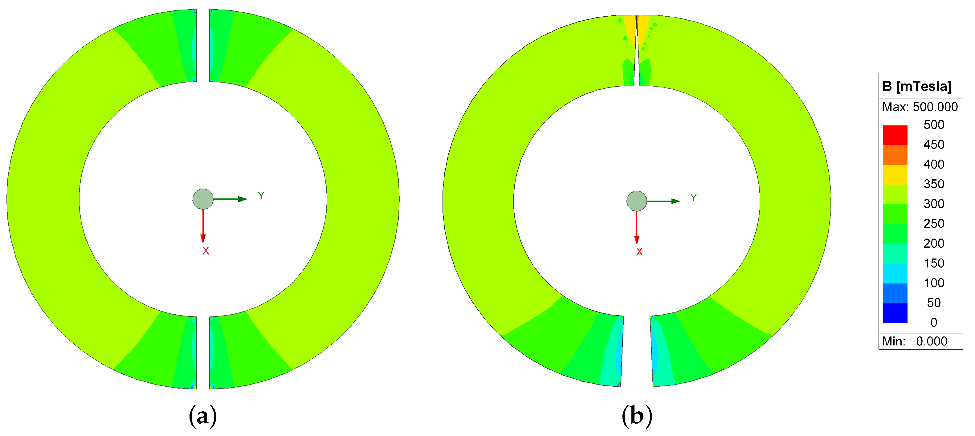
The reason why the HFCT with the asymmetrical air gap configuration had higher flux is illustrated in
Figure 9. The HFCT with an asymmetrical air gap displayed a concentrated flux magnitude at the connection between the cores. This concentration occurred because no fringing effect took place at that point, resulting in lower reluctance compared with the region where the cores were separated by the air gap. As indicated in Equation (
1), an increase in the air gap length leads to a higher reluctance value, thereby impeding the flow of magnetic flux.
As previously discussed, the sensor’s sensitivity is directly proportional to the magnetic flux. Consequently, the HFCT with the asymmetrical air gap configuration exhibited higher sensitivity than those with the symmetrical configuration, due to the concentrated flux path. This characteristic makes the asymmetrical design more suitable for high-voltage equipment monitoring applications.
4.3. Material 78 Simulation Results
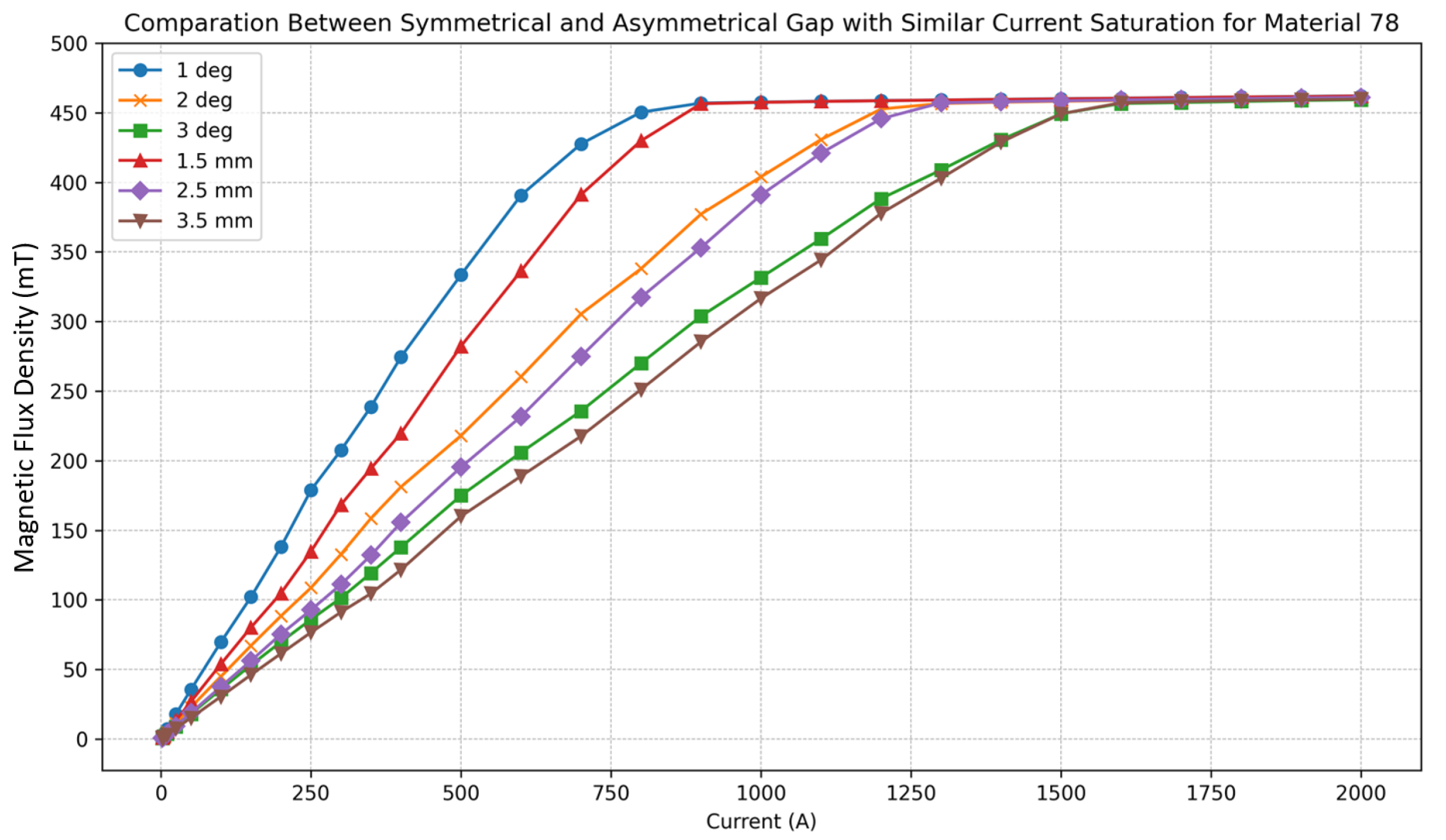
The last simulation evaluated the symmetrical and asymmetrical air gap configurations for Material 78. In this simulation, there were three pairs of data points where the saturation current values were identical. These pairs are as follows: a symmetrical air gap of 1.5 mm (red curve) and an asymmetrical air gap of
(blue curve); 2.5 mm (purple curve) and
(orange curve); and 3.5 mm (brown curve) and
(green curve). The results of this simulation are presented in
Figure 10 and
Figure 11.
The simulation results for Material 78, as shown in
Figure 10 and
Table 3, indicate that its performance was similar to that of Material 43. As presented in
Table 3, an increase in the core’s ability to handle current was observed. Based on the results in
Figure 7, Material 78 saturated at 150 A. However, with the addition of an air gap, saturation occurred at a higher current level. This improvement was attributed to the increased magnetic reluctance introduced by the air gap.
Figure 10 compares the magnetic flux within the core for both symmetrical and asymmetrical air gap configurations, each with the same current saturation level. The results showed that the asymmetrical configurations (blue, orange, and green curves) consistently generated higher flux than their symmetrical counterparts (red, purple, and brown curves). The maximum flux increase occurred at low current levels, reaching approximately 40.78% at 5 A for the
vs. 1.5 mm configuration. Similarly, the
vs. 2.5 mm and
vs. 3.5 mm configurations exhibited flux differences of 32.02% and 30.79%, respectively.
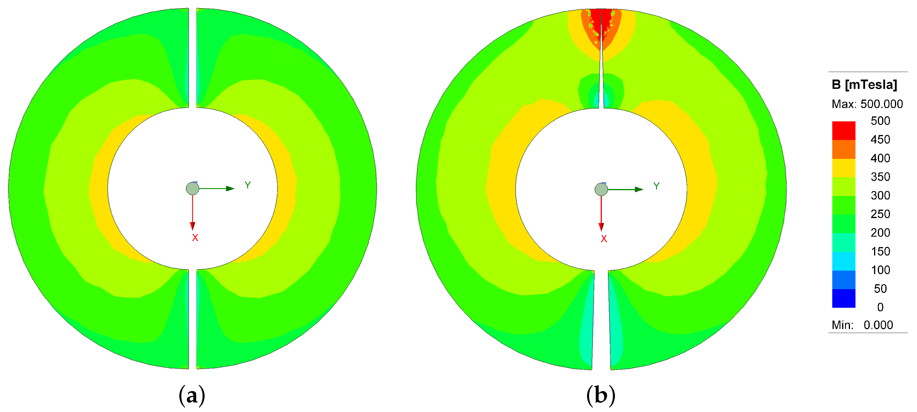
The reason why the HFCT with the asymmetrical air gap configuration exhibited higher flux is demonstrated in
Figure 11. In this configuration, the HFCT showed a concentration of magnetic flux at the connection between the two cores. This occurred because no fringing effect was present at that point, resulting in lower reluctance compared with the region separated by the air gap. As indicated in Equation (
1), reluctance increases with air gap length, making it more difficult for the flux to pass through.
These findings highlight a consistent trend: the asymmetrical air gap configuration increased flux density across all current levels compared with the symmetrical design. While both configurations benefited from the inclusion of an air gap, the asymmetrical design offered a distinct advantage in sensitivity due to its ability to sustain higher flux densities.
However, this benefit comes with a potential drawback. In asymmetrical air gap configurations, the non-uniform magnetic path can lead to localized flux concentration, particularly at the point of closest contact between the core halves. This localized intensification may cause early saturation in specific regions, forming what is referred to as a virtual air gap [
41]. This phenomenon dynamically alters the effective permeability of the core as operating conditions change, potentially resulting in less predictable behavior under varying load currents. In contrast, the symmetrical air gap design distributes magnetic flux more uniformly and consistently, thereby avoiding the formation of a virtual air gap and maintaining stable effective permeability over a wider range of operating conditions.
Therefore, while the asymmetrical air gap design offers improved sensitivity, it may also introduce variability in magnetic performance and saturation behavior that must be carefully considered in high-reliability applications.
5. Discussion
This study provides a detailed evaluation of how different air gap configurations, symmetrical and asymmetrical, affect the performance of HFCTs—particularly in relation to saturation behavior and magnetic flux density. The simulation results showed that introducing an air gap into the HFCT core significantly increased the current saturation threshold, enabling the HFCT to operate under higher currents without reaching saturation. This improvement was primarily due to the increased reluctance caused by the air gap, which regulates magnetic flux density within the core and delays the onset of saturation.
As demonstrated by the results, the asymmetrical air gap configuration consistently produced higher flux densities than the symmetrical configuration. For Material 43, the maximum flux density difference reached approximately 39.77%, while for Material 78, it reached 40.78%. This enhancement is attributed to the concentration of magnetic flux at the core junction in the asymmetrical design, where reluctance is lower due to the absence of fringing effects. The resulting concentrated flux increases the induced voltage in the secondary winding, thereby enhancing the HFCT’s sensitivity and making it more suitable for high-voltage equipment monitoring.
Nonetheless, core saturation remains a critical challenge that limits HFCTs’ ability to accurately detect high-frequency signals. Once the core saturates, the sensor response becomes non-linear, and its dynamic range is reduced. This is particularly problematic in partial discharge (PD) detection, as the sensor may fail to capture weak high-frequency PD signals in the presence of larger low-frequency components. The addition of an air gap helps mitigate this issue by increasing magnetic reluctance, reducing the likelihood of saturation. Despite this, the asymmetrical air gap design offered the best balance between sensitivity and saturation resistance, enabling the HFCT to detect both high currents and weak PD signals effectively.
The findings of this study align with previous research highlighting the role of air gaps in improving saturation resistance [
13,
15,
19,
20,
21,
23]. Unlike symmetrical air gaps, which distribute reluctance uniformly, the asymmetrical configuration provides a more concentrated flux path that significantly enhances sensitivity. This design also reduces fringing effects and offers a more efficient solution for high-frequency current transformers in high-voltage applications.
However, this advantage is not without trade-offs. The asymmetrical air gap induces a non-uniform magnetic path, resulting in localized flux concentration at the narrowest point of the gap. This condition increases the risk of localized saturation and may lead to the formation of a virtual air gap—a dynamic and unpredictable change in the effective magnetic path length. As a result, the core’s overall effective permeability may vary under different operating conditions, especially at high currents or low frequencies.
6. Conclusions
The simulations conducted for both Material 43 and Material 78 provided valuable insights into the performance of HFCT cores with different air gap configurations. The results showed that introducing an air gap significantly increased the current saturation threshold, allowing the HFCT to operate at higher current levels without saturating. This improvement is especially important for high-current applications, as it ensures the functionality of HFCTs under demanding operational conditions.
Among the configurations tested, the asymmetrical air gap consistently outperformed the symmetrical design, exhibiting higher magnetic flux densities. For Material 43, the maximum flux density difference reached approximately 39.77%, while for Material 78, it was 40.78%. This increase directly correlated with enhanced HFCT sensitivity, improving its effectiveness for high-voltage equipment monitoring and partial discharge detection.
However, the asymmetrical air gap configuration is not without limitations. The non-uniform magnetic path may result in localized saturation near the region of minimal separation, leading to a dynamic phenomenon known as a virtual air gap. This condition can cause fluctuations in the core’s effective permeability, potentially introducing variability in HFCT performance across different current levels or frequencies. Recognizing this trade-off is crucial when optimizing design parameters to balance sensitivity with operational stability.
This work introduces a new perspective on HFCT core design by investigating the impact of asymmetrical air gaps on sensitivity and saturation resistance. Simulations using two different materials demonstrated that asymmetrical gaps consistently yielded higher magnetic flux densities than symmetrical counterparts. This improvement is attributed to localized flux concentration at the core interface, where reduced fringing effects result in lower magnetic reluctance. These findings offer meaningful design guidance for developing more effective HFCTs for online partial discharge monitoring in high-voltage equipment. Future work will focus on manufacturing custom core prototypes to experimentally validate the simulation results and further assess the practical advantages of asymmetrical structures.


