Abstract
To reduce the interference from the electromagnetic force caused by coupling coils due to distance changes in a wireless power transfer (WPT) system, this paper conducts a theoretical analysis of the factors influencing the electromagnetic force experienced by the receiving coil. Maxwell electromagnetic simulation is used for modeling and analysis, revealing the trends in the electromagnetic force exerted on the receiving coil. Based on this analysis, a method is proposed that actively adjusts the working frequency of WPT to alter the current phases of the transmitting and receiving coils, thereby regulating the magnitude of the force on the receiving coil. Finally, mechanical tests, including torque experiments, were conducted to validate the proposed method. The electromagnetic force on the coil in the microgravity isolation platform of a space station was reduced from to , a level which plays an important role in improving the microgravity index of the system.
1. Introduction
Wireless power transfer (WPT) technology utilizes principles from electrical engineering, power electronics, and control theory, combining media such as magnetic fields, electric fields, and microwaves to achieve non-contact transmission of electrical energy [1,2,3,4]. This technology overcomes the limitations of fixed positions in traditional wired power transmission, eliminates the risks associated with friction and electrical contact, and enhances the flexibility and safety of systems. Currently, WPT has found widespread applications in electric vehicles, consumer electronics, and the aerospace industry, gradually maturing as a technology.
The Chinese space station has deployed a number of important scientific facilities, both inside and outside the modules, to support a wide range of space science experiments, including space life science and technology, microgravity fluid physics, microgravity combustion science, space materials science, and microgravity fundamental physics [5,6,7,8]. Among these, the levitating experiment platform in the high microgravity cabinet is a key apparatus for creating a high microgravity environment. It isolates various external disturbances by controlling its attitude and position through jet propulsion and is equipped with an electromagnetic levitation experiment platform for installation of scientific payloads.
As shown in Figure 1, the levitating experiment platform adopts a square structure with a highly integrated design concept. It mainly consists of components such as the experimental bench main control unit, WPT, MEMS micro-thruster, intermittent gas supply system, main power line, payload and camera. In order to power the levitating experiment system, the high microgravity experiment cabinet adopts WPT technology, replacing the potential hazards associated with traditional umbilical cord power supply processes. The transmitting coil for WPT is fixed on the high microgravity cabinet, while the receiving coil is dependent on the levitation device. This configuration enables contactless and force-free transmission.
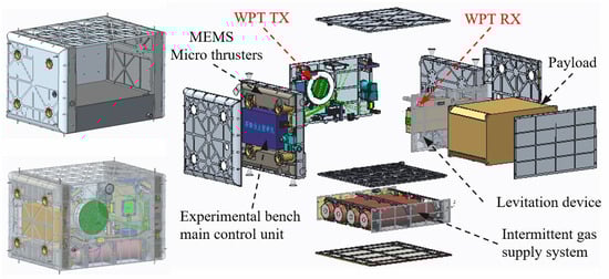
Figure 1.
Schematic layout diagram of the levitating experiment platform.
The WPT technology operates on the principle of electromagnetic induction, enabling the levitation device to draw energy from the induced current within the transmitting coil. However, during the process of electric power transmission, the high-frequency alternating magnetic field generated by the transmitting coil can interfere with the receiving coil, creating electromagnetic-force disturbances. This interference poses a significant challenge, especially for the suspension device inside the high-precision experiment cabinet, which requires an extremely stringent mechanical testing environment. Therefore, employing WPT technology to energize the levitation device within the high microgravity experiment cabinet also generates the influence of electromagnetic-force.
In order to define the microgravity requirements of the space-science experimental payloads, the vibration isolation performance requirements of the experimental payload platform are shown in Table 1. The actuator of the controlled platform needs to generate sufficient main power in time to suppress the vibration of its platform.

Table 1.
The parameters of experimental payloads.
At present, in the field of WPT, the focus has predominantly been on harnessing electromagnetic-forces for various applications, with comparatively limited emphasis on mitigating electromagnetic-force interference.
Studies in the literature [9,10] propose a design scheme for miniature robots based on WPT technology. By adjusting the size of the receiving coil capacitor, the intensity and direction of electromagnetic-force can be precisely controlled, thereby achieving precise control of the robot’s steering and speed. The team further suggests the use of interleaved DC coils to power the miniature robot [11,12], controlling the thrust generated by the miniature robot by adjusting the current in the external DC power coil. Study [13] achieves simultaneous control by electromagnetic-force of multiple robots by using the frequency splitting phenomenon. By setting the operating frequency of the receiving coil to the splitting frequency of the transmitting coil, it is possible to independently control the motion of each miniature robot. Additionally, by adjusting the parameters of the transmitting coil, the number of miniature robots can be increased or decreased. Studies [14,15] use finite element methods to analyze and calculate the uniformity of the magnetic field generated by the Helmholtz coil or Maxwell coil used, successfully achieving control over the motion direction of the receiving robots and reducing motion errors by using position feedback. Studies [16,17,18,19] propose a structural electromagnetic-force smoothing method based on phase difference control. By adjusting the adjustable branch inductance connected in series with a certain branch of the transmitting coil, control over the phase of the current flowing through the coupled coil is achieved. Studies [20,21] propose a method of using a closed magnetic core instead of two open magnetic cores, converting the original electromagnetic attractive force between the two cores into an internal force, and thereby eliminating the influence of an external electromagnetic attraction force.
The present study aims to mitigate the impact of electromagnetic-force on the receiving coil. Theoretical analysis of the coil’s force situation is conducted to identify the primary factors influencing the magnitude of the electromagnetic-force. Finally, a method is proposed to control the electromagnetic-force on the receiving coil by real-time adjustment of the switching frequency. Through simulation and experimentation, it is found that effective control of the electromagnetic-force on the receiving coil is achieved when the transmission distance varies. This validates the correctness of the proposed concept and establishes a theoretical basis and experimental evidence for the application of WPT technology in space stations.
2. Calculation and Analysis of Electromagnetic Forces in Coupling Coils
As mentioned above, the electromagnetic-force on the current-carrying conductor is generated due to the interaction between the magnetic field and the electric current. In order to study the electromagnetic-force characteristics of the coupled coils in WPT systems, the current characteristics of the system are analyzed deeply. Figure 2 shows the mutual inductance model of a loosely coupled transformer.
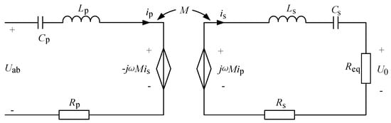
Figure 2.
Series–series compensated topology of the WPT system.
Figure 2 illustrates the most basic series–series compensated topology of the WPT system, in which represents the voltage across the terminals of the transmitting coil, is the mutual inductance between the two coils, is the load, and are the effective values of the currents in the transmitting and receiving coils, and are the internal resistances of the two coils, and are the self-inductances of the transmitting and receiving coils, and are the compensation capacitors for the transmitting and receiving coils and is the switching angular frequency of the inverter.
According to the Kirchhoff’s Voltage Law (KVL) equation,
The current in the receiving coil is obtained as follows:
where is the phase difference between and .
It is assumed that
The magnetic force [22] between the two current-carrying coils can be derived from the general expression for their mutual inductance:
where is the generalized coordinate. The magnetic force has only an axial component because the coils are coaxial. We will begin with the current element of the receiving coil.
The amperage force of the current element on the coil is
represents the electromagnetic induction intensity at the location of the current element, is the radius of the receiving coil and is the angular radian of the current element.
Using cylindrical coordinates, the vector is decomposed as follows:
Then,
where is the column coordinate decomposition of electromagnetic induction and radian, respectively.
Since the current is in the direction , = 0.
Among them,
The magnetic induction intensity of the location of the current element is stimulated by the current of the sending end.
Because of
is produced by , and they have the same phase.
Therefore,
The electromagnetic-force of the receiving coil is obtained as follows.
The electromagnetic-force on the receiving end of the multi-turn coil is
where
According to the above formula, the electromagnetic-force on the receiving coil consists of high-frequency alternating-current force and direct-current bias force . The high-frequency alternating-current force does not contribute propulsion to the coupling mechanism, while the direct-current bias force is non-cancelable and exerts a persistent influence on the coupling mechanism. In order to mitigate the impact of electromagnetic interference on the levitator system, the study focuses solely on the research of the direct-current bias force .
3. Active Regulation Methods for Electromagnetic Force
Assume that the frequency of the resonant cavity at the receiver is , the switching frequency of the system is , and the transmission distance is .
According to Equation (20), the electromagnetic-force is mainly affected by the current in the transmitting coil, mutual inductance , operating angular frequency , and the phase difference between the currents. The phase difference directly determines the magnitude and direction of the electromagnetic-force.
The levitation system’s free-drifting state leads to changes in the relative positions of the receiving and transmitting coils, which affects the resonant relationship of the coupling coil. In this case, the current phase difference , resulting in electromagnetic-force interference.
The specific rationale is as follows:
- (1)
- When is kept at the rated position,
- (2)
- When increases,
Then,
At this time, the receiving end exhibits capacitive characteristics, and the current phase difference , leading to . The electromagnetic-force on the receiving coil, resulting in an attractive force between the two coils.
If the fixed frequency operating mode is adopted, the receiving end will be drawn closer until a repulsive force is generated. In ideal conditions, it would undergo oscillations back and forth until equilibrium is reached at . However, in reality, interference may cause the equilibrium point to deviate. Additionally, during the attraction process, the proximity may lead to overvoltage protection in the subsequent DC/DC stage.
If a variable frequency operating mode is adopted, as the transmission distance increases, the operating frequency is reduced to adjust the magnitude of the current phase difference , maintaining it near . This ensures that the electromagnetic-force on the receiving end is minimized.
- (3)
- When decreases,
Then,
At this time, the receiving end exhibits inductive characteristics, and the current phase difference , leading to . The electromagnetic-force on the receiving coil, resulting in a repulsive force between the two coils.
If the fixed frequency operating mode is adopted, the receiving end will be pushed away until an attractive force is generated. In ideal conditions, it would oscillate back and forth until equilibrium is reached at . However, in reality, interference may cause the equilibrium point to deviate. Additionally, during the repulsion process, the distance may become too great, leading to power loss.
If a variable frequency operating mode is adopted, as the transmission distance decreases, the operating frequency is increased to adjust the magnitude of the current phase difference , maintaining it around . This ensures that the electromagnetic-force on the receiving end is minimized.
Figure 3 is a flowchart of frequency control. When the transmission distance changes, adjusting the system’s switching frequency alters the phase difference to minimize the electromagnetic-force on the receiving coil. To measure the position changes of the receiving coil, three sets of laser ranging sensors are employed. Each set measures one degree of freedom of the coil’s position, providing changes in the coil’s motion along the , and axes. The position data obtained from the receiving laser displacement sensor provides the position , , of the coil during motion.
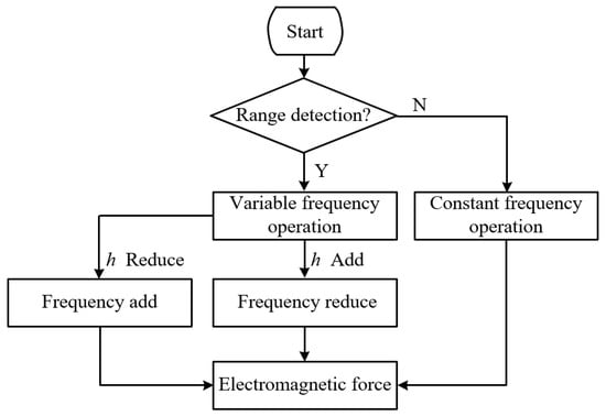
Figure 3.
Flowchart of frequency control.
Figure 4 below illustrates the frequency tracking control diagram for WPT. The frequency tracking adjustment system mainly consists of laser ranging sensors, current sampling circuits, zero-crossing comparators, DPLL (digital phase-locked loop), and driver circuits. The specific implementation process is as described in the following.
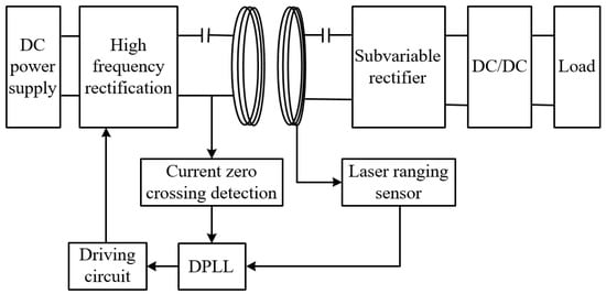
Figure 4.
Frequency tracking control diagram.
The laser ranging sensor continuously detects the position of the receiving coil in real time and sends the collected position information to the FPGA to adjust the system’s operating frequency. The current-sensing circuit continuously samples the current flowing through the transmitting coil. Subsequently, this current is processed by zero-crossing comparison circuits to generate square wave signals that are in phase and frequency with . The DPLL compares with the feedback-driven signal , generating a driving logic signal at the same frequency as . Finally, this driving logic signal enters the driver circuit to produce four-channel PWM waveforms to control the switching transistors.
The paper adopts a frequency tracking control method based on a PI-controlled digital phase-locked loop (DPLL). To facilitate the study and determination of the impact of the proportional and integral parameters of the internal loop filter of the PI-control digital phase-locked loop on frequency adjustment, it is necessary to establish its mathematical model. Figure 5 illustrates the flowchart of the mathematical model of the PI-controlled digital phase-locked loop.
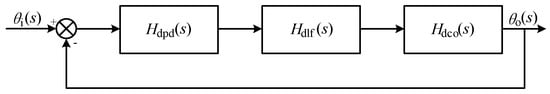
Figure 5.
Mathematical model of the PI-controlled phase-locked loop.
In the diagram above, denotes the phase of the input signal , while represents the phase of the output signal . Additionally, , , and correspond to the transfer functions of the phase detector, loop filter, and voltage-controlled oscillator (VCO), respectively.
where represents the system clock frequency, and denotes the frequency of the input signal.
The transfer function of a loop filter with proportional and integral characteristics, essentially a PI controller, can be represented as follows:
where and represent the proportional and integral coefficients of the loop filter, respectively.
Near the lock frequency point, the transfer function of the voltage-controlled oscillator (VCO) equals the rate of change of the output phase with respect to its input division ratio . Therefore, the transfer function of the frequency divider can be expressed as
Therefore, the transfer function of the system near the lock frequency point can be obtained as follows:
In the local dynamic model, when the input signal varies around the lock frequency point such that , the transfer function can be simplified as
From Equation (30), it can be observed that the system is a typical second-order system. According to the general form of a second-order system transfer function, the damping ratio and natural frequency of the system can be obtained as follows:
With as the assumed input signal frequency, the dynamic performance of the DPLL solely depends on the parameters and of the loop filter when the input signal is constant. The impacts of different values of and on the system performance are illustrated in Figure 6.
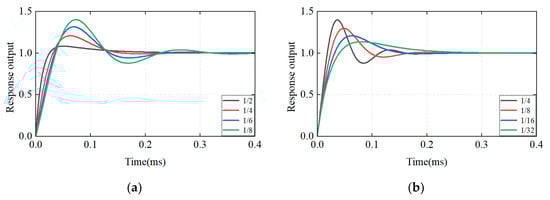
Figure 6.
Different parameter settings yield distinct step response curves for the system. (a) , changes; (b) , changes.
When is constant, a larger leads to better system stability and faster locking speed. According to Equation (31), an excessively large results in a large damping ratio. According to Equation (32), the natural angular frequency remains constant in this case. Therefore, an excessively large makes the system overly sensitive to noise in the input signal. When is constant, a larger leads to faster system response, but the stability margin decreases. According to Equation (31), an excessively large results in a small damping ratio, leading to excessive overshoot in the system.
According to the analysis above, when the phase error is large, a larger should be chosen, while should be kept relatively small. Preliminary phase adjustment is mainly achieved by the proportional element, which both ensures response speed and avoids excessive overshoot. When the phase error is small, a smaller should be chosen, while should be larger. This ensures quick elimination of the steady-state error introduced by the proportional element after preliminary phase adjustment.
Figure 7 shows the curves depicting the variation of the phase difference and electromagnetic-force with the switching frequency . It can be seen from the figure that when the changing range of switching frequency is , the electromagnetic-force of the receiving coil is in a generally monotonic state. Moreover, during this range, the system’s power transfer meets the required specifications.
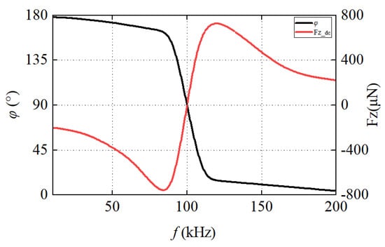
Figure 7.
Curve depicting the variation of the phase difference with the switching frequency .
Therefore, to control the impact of electromagnetic-forces on the receiving coil, the objective can be achieved by adjusting the working frequency.
4. Simulation and Experimental Verification
Through modeling and simulation, we analyze the influence of each parameter on the electromagnetic-force .
4.1. Simulation Analysis
In order to illustrate the influence of electromagnetic-force generated in the receiving coil during WPT, 3D modeling of the transmitting and receiving coils was conducted using ANSYS Maxwell 2021 R2 finite element software. The coil model is shown in Figure 8a, and the outer circuit of the coil is shown in Figure 8b.
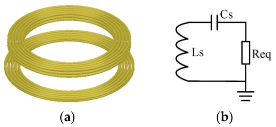
Figure 8.
Simulation model. (a) Coil model; (b) External circuit.
The simulation emulates the actual circuit, and the parameters for the simulation setup are listed in Table 2, below. represents the peak current of the transmitting coil, and the coil material is copper.
Table 2.
Simulation model parameters.
The simulation procedure consisted of three stages: (1) A 3D field simulation was performed to find the magnetic field distribution and induced voltage. (2) The induced secondary current was simulated using the circuit simulator in consideration of the WPT circuit and the switching frequency was adjusted to the maximum current of the receiving coil. (3) The propulsion forces were simulated using a 3D field solver, again based on the induced current from the circuit simulation and incident magnetic field from the primary coil .
The simulation was configured with set to and a switching frequency of . The variables being scanned are and , where represents the axial separation at the coil’s center along the -axis, and represents the eccentricity along the -axis.
Figure 9a,b, respectively, show the variation curves of the electromagnetic-force experienced by the receiving coil under different transmission distances and eccentricities. From Figure 9a, it can be observed that as the transmission distance increases, the induced current in the receiving coil gradually decreases, leading to a reduction in the electromagnetic-force. The farther the transmission distance, the less electromagnetic-force interference. In Figure 9b, when there is a lateral displacement in the receiving coil, the change in electromagnetic-force is relatively small.
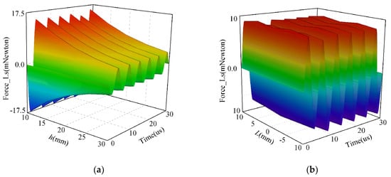
Figure 9.
Electromagnetic force experienced by the receiving coil at . (a) Varying , ; (b) , varying .
Figure 10 indicates that the frequency of the electromagnetic-force on the receiving coil is twice that of the current’s frequency.
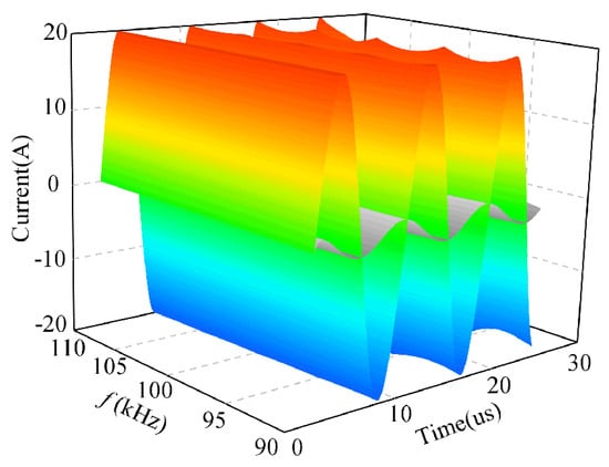
Figure 10.
Current curves of the transmitting and receiving coils as the frequency varies.
From Figure 11, it can be observed that at a fixed switching frequency, the electromagnetic-force experienced by the receiving coil gradually decreases to zero as the transmission distance increases, and then gradually increases. However, when operating in variable frequency mode, as the transmission distance changes, the electromagnetic-force experienced on the receiving coil under different switching frequencies evinces a zero-point phenomenon, that is, the electromagnetic-force is zero.
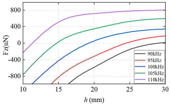
Figure 11.
Variation curves of electromagnetic force with frequency and distance.
In Figure 12, when the receiving coil undergoes lateral displacement, the electromagnetic-force it experiences remains at the level. As the eccentricity approaches the system’s switching frequency, the electromagnetic-force caused by eccentricity becomes smaller.
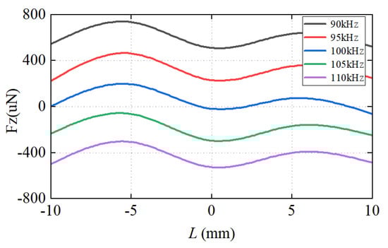
Figure 12.
Variation curves of electromagnetic force with frequency and eccentricity.
In summary, by adjusting the switching frequency of WPT, the interference of the electromagnetic-force on the receiving coil can be effectively reduced, so that the electromagnetic-force can be kept at the order of .
4.2. Experimental Verification
In order to verify the influence of electromagnetic-force on the receiving coil, a mechanical torsion test was conducted in the Microgravity Laboratory of the Chinese Academy of Sciences. The experimental device is shown in Figure 13.
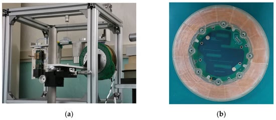
Figure 13.
Torsion weighing test platform. (a) Experimental platform; (b) Coil.
Testing was conducted using a torsion balance and a laser rangefinder, with the testing precision reaching the level of . To reduce the high-frequency internal resistance caused by the skin effect in the coil, Litz wire winding was employed in the coupler’s coil. Since the highest quality factor was measured at the resonant frequency of , the matching capacitance for both the transmitting and receiving coils was tuned to . In order to enhance the efficiency of WPT and achieve soft-switching characteristics, the operating frequency was set slightly higher than the resonant frequency.
The detailed parameters of the coil are provided in Table 3.
Table 3.
Parameters of a WPT coil.
- (1)
- The magnitude of electromagnetic force on the receiving coil at different positions
In Figure 14a,b, it can be observed that at a transmission distance of , the electromagnetic-force on the receiving coil is repulsive, and the electromagnetic-force is about , with a switching frequency of . When the eccentricity is , the electromagnetic-force is about , and the system’s switching frequency is .
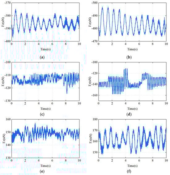
Figure 14.
The magnitude of the electromagnetic force on the receiving coil at different transmission distances. (a) , ; (b) , ; (c) , ; (d) , ; (e) , ; (f) , .
In Figure 14c,d, it can be observed that at a transmission distance of , the electromagnetic-force on the receiving coil is repulsive, and the electromagnetic-force is about , with a switching frequency of . When the eccentricity is , the electromagnetic-force is about , and the system’s switching frequency is .
In Figure 14e,f, it can be observed that at a transmission distance of , the electromagnetic-force on the receiving coil is attractive, and the electromagnetic-force is about , with a switching frequency of . When the eccentricity is , the electromagnetic-force is about , and the system’s switching frequency is .
Table 4 presents a comparison between simulation-based and experimental data as to the electromagnetic-force magnitude exerted on the receiving coil at various positions.
Table 4.
Simulation-based and experimental results.
Due to the presence of magnetic shielding materials around the coupled coils, as well as the influence of circuit boards and mounting metal surfaces, the electromagnetic-force is further affected. Additionally, there may be errors in the actual transmission distance measured using laser rangefinder sensors. Therefore, there will be slight differences between simulation and experimentation.
In the coaxial scenario, when the transmission distance is minimal, the electromagnetic-force exerted on the receiving coil is at its maximum and repulsive. At this point, the system’s switching frequency is also at its maximum value. As increases, the repulsive force on the receiving coil decreases until, at a certain position, the receiving coil is no longer affected by electromagnetic-force, and the phase difference is . At this point, the switching frequency of the switches is at the rated value. As is further increased, the electromagnetic-force on the receiving coil becomes attractive, and the greater becomes, the more the attractive force increases. When the transmission distance reaches its maximum, the attractive force on the receiving coil also reaches its maximum, and the system’s switching frequency is minimized.
When the transmission distance is fixed, any deviation in the or direction by the receiving coil results in an increase in the electromagnetic-force exerted on it, causing a slight decrease in the system’s switching frequency. As the transmission distance increases, the impact of the deviation on the electromagnetic-force diminishes.
In summary, when the levitator is in free drift, adjusting the system’s switching frequency ensures that the electromagnetic-force interference on the receiving coil is less than , meeting the experimental requirements of space science.
- (2)
- Power and efficiency curves
The experiment was conducted in the levitation laboratory. The test results of WPT under the full-load conditions are shown in Figure 15, when the transmission distance is , the transmission power of the system is ; when the transmission distance is , the output power is . The system demonstrated a maximum efficiency of 78%, meeting the power supply requirements of the levitation system.
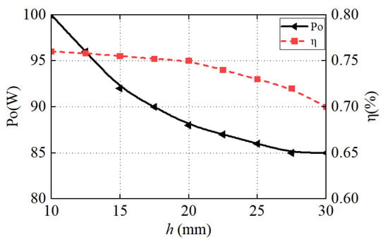
Figure 15.
Power and efficiency curves of WPT at the rated state.
5. Discussion
To mitigate the electromagnetic-force interference within the high-microgravity experimental cabinet during WPT, the research described utilizes adjustments to the system’s switching frequency to control the magnitude and direction of the electromagnetic-force. However, it is noted that further discussion is required regarding the effectiveness of this method, based on theoretical analysis and experimental findings.
- (1)
- Otherness
Compared to the method of adjusting the capacitance of the receiving coil, as described in [10], this paper’s approach of adjusting the system’s switching frequency enables real-time control of the magnitude and direction of the electromagnetic-force on the receiving coil. This effectively avoids the need for real-time changes to the resonant capacitance of the receiving end, thus enhancing the system’s flexibility. Although the research described in [20] reduces the electromagnetic-force on the receiving coil to zero, it does not fulfill other requirements of the space-based high-precision experimental cabinet.
- (2)
- Limitations
Small variations in transmission distance directly affect the magnitude and direction of the electromagnetic-force, imposing strict requirements on the measurement of the receiving coil’s position. The more accurately the transmission distance is measured, the more precise the control of the magnitude and direction of the electromagnetic-force, resulting in smaller errors. Additionally, as the transmission distance increases, it is necessary to reduce the switching frequency, leading to a decrease in the overall transmission power and efficiency of the system. Therefore, this method is suitable for scenarios in which the transmission distance varies within the range of millimeters and where there are no stringent requirements on power and transmission efficiency.
- (3)
- Future research direction
WPT is a current research hotspot and has found wide application in many fields. Research related to this technology primarily focuses on improving transmission power and efficiency. However, studies on the electromagnetic-force interference generated during WPT are relatively scarce. It is worth contemplating and researching how to reduce the impact on surrounding electronic devices during the power supply process.
6. Conclusions
In order to reduce electromagnetic-force interference caused by the free drift of the receiving coil in WPT systems, this paper proposes a method of adjusting the switching frequency to control the magnitude and direction of the electromagnetic-force on the receiving coil. When the transmission distance changes, the actual transmission distance is measured using a laser ranging sensor, and the system’s switching frequency is dynamically adjusted, effectively reducing the impact of the electromagnetic-force on the receiving coil. Experimental results demonstrate that as the transmission distance changes from to , the system’s switching frequency changes from to , and the electromagnetic-force on the receiving coil changes from to . Therefore, the feasibility of the control method has been verified through simulation and experiment, and the influence of the electromagnetic-force can meet the requirements of a high-microgravity experimental cabinet, which lays a theoretical and experimental basis for the application of WPT technology in space stations.
Author Contributions
Conceptualization, Y.H. and W.D.; Methodology, Y.H.; Software, X.L. and L.M.; Validation, L.M.; Investigation, Y.H. and W.D.; Resources, W.D., X.L. and H.Z.; Data curation, L.M.; Writing—original draft, Y.H.; Writing—review & editing, Y.H., W.D. and X.L.; Visualization, L.M.; Supervision, W.D. and H.Z.; Project administration, W.D. and X.L.; Funding acquisition, X.L. All authors have read and agreed to the published version of the manuscript.
Funding
This research was funded by the Chinese Manned Space Program—Space Utilization System (412021000031) and National Key Research and Development Program of China (2022YFB3604004).
Data Availability Statement
The data presented in this study are available in this article.
Conflicts of Interest
The authors declare no conflict of interest.
References
- Zhang, Z.; Pang, H.; Georgiadis, A.; Cecati, C. Wireless power transfer—An overview. IEEE Trans. Ind. Electron. 2018, 66, 1044–1058. [Google Scholar] [CrossRef]
- Patil, D.; McDonough, M.K.; Miller, J.M.; Fahimi, B.; Balsara, P.T. Wireless power transfer for vehicular applications: Overview and challenges. IEEE Trans. Transp. Electrif. 2018, 4, 3–37. [Google Scholar] [CrossRef]
- Xu, F.; Wong, S.C.; Chi, K.T. Overall loss compensation and optimization control in single-stage inductive power transfer converter delivering constant power. IEEE Trans. Power Electron. 2021, 37, 1146–1158. [Google Scholar] [CrossRef]
- Ming, X.; Qingxin, Y.; Pengcheng, Z.; Jianwu, G.; Yang, L. Application status and key issues of wireless power transmission technology. Trans. China Electrotech. Soc. 2021, 36, 1547–1568. [Google Scholar]
- Gao, M.; Zhao, G.; Gu, Y. Recent progress in space science and applications of China’s space station in 2020–2022. Chin. J. Space Sci. 2022, 42, 503–510. [Google Scholar] [CrossRef]
- Wang, S.K.; Wang, K.; Zhou, Y.L.; Yan, B.; Li, X.; Zhang, Y.; Wang, A.P. Development of the varying gravity rack (VGR) for the Chinese space station. Microgravity Sci. Technol. 2019, 31, 95–107. [Google Scholar] [CrossRef]
- Zhang, Y.; Dong, S.; Wang, K.; Zhou, Y.; Sheng, Q.; Tan, H. Design, simulation and test of thermal control system of centrifuge for space utilization. Microgravity Sci. Technol. 2020, 32, 761–772. [Google Scholar] [CrossRef]
- Hu, Y.; Li, X.; Dong, W.; Zhang, H.; Wang, X. The application progress of wireless power transfer in space utilization field. In Proceedings of the 2023 International Conference on Wireless Power Transfer (ICWPT), Weihai, China, 13–15 October 2023; pp. 520–532. [Google Scholar]
- Kim, D.; Kim, M.; Yoo, J.; Park, H.; Ahn, S. Magnetic resonant wireless power transfer for propulsion of implantable micro-robot. J. Appl. Phys. 2015, 117, 17E712. [Google Scholar] [CrossRef]
- Kim, D.; Park, J.; Park, H.H.; Ahn, S. Generation of magnetic propulsion force and torque for microrobot using wireless power transfer coil. IEEE Trans. Magn. 2015, 51, 8600104. [Google Scholar] [CrossRef]
- Kim, D.; Hwang, K.; Park, J.; Park, H.H.; Ahn, S. Miniaturization of implantable micro-robot propulsion using a wireless power transfer system. Micromachines 2017, 8, 269. [Google Scholar] [CrossRef] [PubMed]
- Kim, D.; Ahn, S. Wireless Power Transfer-Based Microrobot with Magnetic Force Propulsion Considering Power Transfer Efficiency. J. Electromagn. Eng. Sci. 2022, 22, 488–495. [Google Scholar] [CrossRef]
- Narayanamoorthi, R.; Juliet, A.V.; Chokkalingam, B. Frequency splitting-based wireless power transfer and simultaneous propulsion generation to multiple micro-robots. IEEE Sens. J. 2018, 18, 5566–5575. [Google Scholar] [CrossRef]
- Song, S.; Song, S.; Meng, M.Q.H. Electromagnetic actuation system using stationary six-pair coils for three-dimensional wireless locomotive microrobot. In Proceedings of the 2017 IEEE International Conference on Information and Automation (ICIA), Macau, China, 18–20 July 2017; pp. 305–310. [Google Scholar]
- Zhang, Q.; Song, S.; Song, S. Study on magnetic field model of independent circular coils for wireless manipulation of microrobots. In Proceedings of the 2017 IEEE International Conference on Information and Automation (ICIA), Macau, China, 18–20 July 2017; pp. 1137–1142. [Google Scholar]
- Zhang, X.; Ren, Y.; Sha, L.; Yang, Q.; Ni, X.; Wang, F. Analysis of dynamic characteristics of foreign metal objects under electromagnetic force in high-power wireless power transfer. Energies 2020, 13, 3881. [Google Scholar] [CrossRef]
- Zhang, X.; Ni, X.; Wei, B.; Wang, S.; Yang, Q. Characteristic analysis of electromagnetic force in a high-power wireless power transfer system. Energies 2018, 11, 3088. [Google Scholar] [CrossRef]
- Zhang, X.; Wang, F.; Ni, X.; Ren, Y.; Yang, Q. Structure electromagnetic force analysis of WPT system under fault conditions. IEEE Access 2020, 8, 152990–153000. [Google Scholar] [CrossRef]
- Zhang, X.; Yuan, Z.; Yang, Q.; Li, Y.; Zhu, J.; Li, Y. Coil design and efficiency analysis for dynamic wireless charging system for electric vehicles. IEEE Trans. Magn. 2016, 52, 8700404. [Google Scholar] [CrossRef]
- Guo, S.Z. Research on Inductively Coupled Wireless Power Supply Technology with Perturbation Force. Ph.D. Thesis, Xidian University, Xi’an, China, 2019. [Google Scholar]
- Han, G.; Wei, Y.; Yan, L. Ana lysis of electromagnetic force on wireless charging structure. Wirel. Netw. 2023, 1–10. [Google Scholar] [CrossRef]
- Babic, S.I.; Akyel, C. Magnetic force calculation between thin coaxial circular coils in air. IEEE Trans. Magn. 2008, 44, 445–452. [Google Scholar] [CrossRef]
Disclaimer/Publisher’s Note: The statements, opinions and data contained in all publications are solely those of the individual author(s) and contributor(s) and not of MDPI and/or the editor(s). MDPI and/or the editor(s) disclaim responsibility for any injury to people or property resulting from any ideas, methods, instructions or products referred to in the content. |
© 2024 by the authors. Licensee MDPI, Basel, Switzerland. This article is an open access article distributed under the terms and conditions of the Creative Commons Attribution (CC BY) license (https://creativecommons.org/licenses/by/4.0/).