Abstract
This paper proposes an all-digital calibration algorithm that utilizes a reference channel to suppress the timing mismatch in the Time-Interleaved Analog-to-Digital Converter (TIADC). The output of the reference channel is aligned with each sub-channel in turn, therefore enabling the simultaneous sampling and conversion of the same input signal. First, the statistical characteristics across the channels are employed for estimating the timing mismatch; then, by comparing the output difference between the reference channel and the sub-channels that are sampled simultaneously, the deviation of the derivator can be calibrated. Finally, combining both calibration results yields an accurate final output. This proposed algorithm provides an effective solution to improve TIADC performance in high-speed data acquisition systems. The proposed architecture is applied to a 12-bit 2.4 GS/s four-channel TIADC model, and then its effectiveness is verified. The simulation results exhibit that the Effective Number Of Bits (ENOB) at an input signal frequency of 984 MHz shows a remarkable improvement from 6.88 bits to 11.92 bits. The effectiveness of this technique is also demonstrated through the off-chip calibration of a commercial 12-bit four-channel 2 GS/s TIADC using a 680 MHz input signal that is based on the actual chip results.
1. Introduction
The analog-to-digital converter is a bridge that is applied to convert analog signals into discrete signals [1]. It is widely used in various fields, such as wireless communication, electronic radar, medical equipment, etc. With the progress of the time, the demand for ADC is growing. The essential criteria for ADC are higher precision, higher speed, lower power consumption, etc. It is difficult for a single-structure ADC to incorporate all these three factors in the existing technologies. Fortunately, TIADC can solve this problem effectively [2]. The TIADC can double the sampling rate of the whole ADC, and it can easily reach the sampling rate of 1 GS/s [3].
The TIADC is composed of M sub-channels. Due to the manufacturing process, layout routing, temperature, voltage, and other such factors, mismatches between the sub-channels will occur, such as offset mismatch, gain mismatch, and timing mismatch [3]. Indeed, the degradation of the Signal-to-Noise Ratio (SNR) and Spurious Free Dynamic Range (SFDR) of the output signal are most probably connected to these mismatches. The system as a whole cannot satisfy the demands for high precision and high speed unless these errors are calibrated accurately. The common calibrations for offset and gain mismatches involve the accumulation and averaging of the input signal, and this is followed by its subtraction from the original signal. This approach is both straightforward and efficient [4]. The calibration of timing mismatch is the most challenging compared to other mismatches [2]. Therefore, the architecture proposed in this paper was mainly designed to solve the timing mismatch problem.
The calibration of timing mismatches can be accomplished through methodologies that are akin to those employed in analog loop calibration. The analog loop calibration method primarily involves filtering the TIADC sampling clock, and it is coupled with the adjustment of clock phases through the observation of output discrepancies in the digital domain for each sub-ADC channel. This procedure serves to effectively eliminate sampling timing mismatches [5,6]. Ref. [5] introduced a kind of foreground calibration technology based on an analog auxiliary circuit, which predominantly depended on the filtration efficacy of the analog domain filter circuit with respect to the clock signal. However, this method exhibited significant limitations, and its calibration performance was greatly influenced by temperature variations, process variations, and voltage fluctuations. Ref. [6] introduced a coarse adjustment technique for an analog variable delay line. Nonetheless, the fixed and coarse step sizes in this method imposed limitations on its effective adjustment range, as discerned from experimental analysis.
In contrast, all-digital calibration technology offers high reliability and powerful portability advantages, therefore effectively addressing the aforementioned issues. Several methodologies have been developed to address timing mismatch calibration within an all-digital domain. The investigations of all-digital calibration structures are mainly focused on two parts: the estimation method and the compensation method.
Thereinto, the predominant error estimation methodologies entail the utilization of the cross-correlations among sub-channels [2,3,7,8,9,10,11,12], or the introduction of a reference channel [13,14,15,16]. Based on the correlations among sub-channels, a complex computational matrix is commonly constructed. For example, Ref. [9] introduced an estimation methodology that employs signal modulation for the construction of an error coefficient matrix. Nevertheless, a notable limitation was observed in terms of the sluggish convergence rates (110 k) and constraints associated with finite input bandwidths. Please note that these methods that are predicated on signal modulation or Hadamard matrix operations are infrequently employed in practical applications due to their elevated computational intricacy. Calibration structures that are predicated on reference channels commonly exhibit relative simplicity. The estimation process can be construed as the assessment between a designated sub-channel and the reference channel. The calibration procedure can be delineated as a specialized form of a dual-channel calibration structure, i.e., one that is impervious to the influence of channel count expansion. Notably, this configuration is frequently characterized by diminished hardware consumption. In the paradigm of sub-channel cross-correlation, the escalation in the number of channels engenders an exponential amplification in the complexity of the formulated system of error functions. This not only augments the intricacy of design but also imparts a substantial inefficiency in terms of hardware utilization. Ref. [14] proposed an estimation methodology, one which entailed the application of a high-pass filter for the processing of input slopes that pertained to both the sub-ADC and the reference ADC. However, the reference channel necessitated a significant degree of precision, thus resulting in substantial hardware consumption with many multiplication–addition units in the usage of a high-precision filter case. Additionally, the calibration performance gradually deteriorates with increasing frequency, which is a common issue faced by most calibration structures [3,13,14,15]. Typically, increasing the order of the filter and parallel correlation derivative [6] was employed to mitigate this deterioration, but it inevitably led to an increase in hardware consumption. Ref. [16] proposed an innovative split-based structure. This design segregated an M-channel TIADC into two segments that featured mutually co-prime operating frequencies. At each sampling instance, each segment actively provides a sub-ADC channel as a reference for the other. The utilization of the difference in the outputs from the dual paths serves as a new thought for actively extracting the temporal misalignment information between channels. Ref. [17] proposed a methodology for error computation based on the detection of the monotonic trends in the sampled data from sub-channels and reference channels, whereby they then subsequently applied cumulative difference accumulation. It is noteworthy that this structural approach eliminates the necessity for any multiplication or division operations. However, there have only been a few reports about timing mismatch calibration techniques based on reference channels, and their effectiveness needs further verification and improvement.
Most compensation methods rely on either filtering techniques [18,19,20,21] or Taylor expansion [11,22,23]. Numerous structures of the commonly employed filter are subjects of the study, with a substantial portion of researchers directing their investigations toward fractional-delay filters and perfect-reconstruction filters. Ref. [19] introduced a methodology that employed fractional filters for the phase adjustment in the input signal. Ref. [20] introduced a methodology that utilized the perfect reconstruction filters to efficaciously rectify errors in reconstructed signals. However, this approach consumed high hardware and substantial power. In addition, the structures based on Taylor series expansion are highly regarded for their low complexity, rapid convergence, and notable efficacy, which make them equally popular. Ref. [11] utilized a Taylor series expansion to approximate the error terms within the output signal. The calibration of the errors in the output signal was achieved through the consideration of the time misalignment errors and the derivatives of the input signal. The conventional approach to optimizing the output performance and the input signal bandwidth in calibration algorithms typically relies on the degree of differentiation or the second-order differential term. However, the exponential increase in the hardware consumption has not been positively linked to the commensurate improvements in the input bandwidth.
In this paper, an all-digital calibration structure is proposed to address the aforementioned issues. A reference channel is used to extract the timing mismatch of each sub-channel. The compensation structure is formulated based on the expansion of the first-order Taylor series. The derivator which is optimized with the Richardson extrapolation is based on the first-order numerical differential of the Lagrange interpolation polynomial of the 5-point formula. The optimization of the derivator circuit’s structure, as is outlined in this paper, aims to minimize the hardware consumption and the overall resource utilization. In addition, an auxiliary circuit is introduced to further enhance the output precision and performance, which improves the overall accuracy and efficiency. This design manifests attributes including the expeditious convergence, the compact hardware footprint, and the straightforward architectural framework. This paper is organized as follows. Section 2 describes the construction of the TIADC module and the merits of the proposed calibration technique. Section 3 shows the simulation results which verify the effectiveness of the technique. Section 4 is mainly used to discuss the advantages and disadvantages of the proposed algorithm as well as the direction of the future work. Finally, the conclusions are drawn in Section 5.
2. Timing Mismatch Model and Proposed Timing Mismatch Calibration Structure
Assuming that the prior calibrations with the help of a reference ADC [24] have been made for other mismatches (i.e., offset and gain mismatches), we only need to focus on the calibration of the timing mismatch. Figure 1 shows the structure of the M-channel TIADC with the reference channel. The output of the optimal M-channel TIADC system can be expressed as
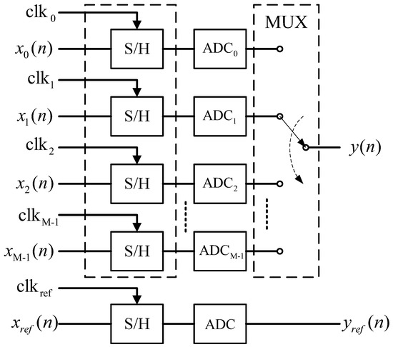
Figure 1.
The structure of the M channel TIADC. is the sample clock of the sub-ADC. is the sample clock of the reference ADC. S/H stands for the sample holder.
In (1), is the sampled value of the input signal at the time , where represents the timing mismatch of the sub-channel and represents the sampling period. The signal of the entire TIADC can be expressed as
In the actual circuit, the timing mismatch is much smaller than , . represents the timing mismatch coefficient of the sub-channel.
2.1. Timing Mismatch Compensation
In practice, the timing mismatch is typically negligible in comparison to the sampling period. As a result, the first-order Taylor series is employed for approximation [6]. The function of the timing mismatch compensation on the sub-channel is expressed as
where represents the differential value of the output from the sub-channel. The deviation coefficients of the derivator exhibit frequency-dependent variations during the execution of the differentiation operation [25]. Therefore, the relationship between the output of the derivator () and the ideal derivative () can be mathematically expressed as
where represents the deviation coefficient of the derivator. (3) is rewritten as
The deviation coefficient of the derivator is solely dependent on the frequency. Figure 2 shows the implementation architecture of the timing mismatch calibrations.
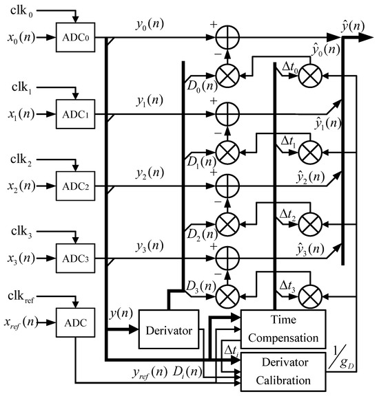
Figure 2.
Proposed calibration system of the timing mismatch and the derivator deviation coefficient with the reference channel.
2.2. Estimation Architecture
In this sub-section, this paper presents an adaptive estimation method that utilizes the first-order statistics to address the timing mismatches. The estimation model is based on a four-channel model with an additional channel for reference. The sampling frequency of TIADC is . The sampling frequency of the sub-channel is . The sampling frequency of the reference channel is . The sampling values of the reference channel are aligned with each sub-channel in turn. The sampling timing of each sub-channel ADC and the reference channel ADC is illustrated in Figure 3.
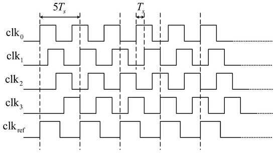
Figure 3.
TIADC calibration sampling timing.
The specific sampling sequences are extracted through down-sampling. The output sequence of the sub-channel after down-sampling is expressed as
The corresponding output sequence of the reference channel needs to be extracted accordingly, which can be formulated as
where represents the output of the reference channel, which can be expressed as
The estimation of the timing mismatch requires the utilization of the cross-correlation function between the sub-channel and the reference channel. The reference channel output sequence ( for , stands for modulus function) of the corresponding sub-channel can be denoted as
the cross-correlation function between the sub-channel and the reference channels after down-sampling, i.e., and , respectively, is expressed as
where expresses the mathematical expectation. It is realized through Modified Moving Average (MMA) [23], which is shown in Figure 4. It is expressed as
where and are the output and the input, and represents a constant smoothing factor. The recursive calculation of the average output relies on both the preceding result and the current input term . The (11) is commonly utilized in Digital Signal Processing (DSP), and the recursive calculation of the computing moving averages. In terms of the hardware implementation, opting for a sample period—with k being any positive integer is proved to be advantageous since multiplying the signal by can be efficiently accomplished via the proper arithmetic shifting by k bits instead of employing a hardware multiplier. expresses the cross-correlation of and . By the first-order Taylor series approximation, it could be approximately expressed as
where is the derivative of the autocorrelation of the input signal. It could be expressed as
where is the derivative of the reference signal. From (10) and (12), the cross-correlation value between and is expressed as
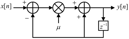
Figure 4.
The Modified Moving Average (MMA) filter. stands for the D flip-flop.
Obviously, the cross-correlation value between and is expressed as
To obtain the timing mismatch, the difference of the cross-correlation values can be derived by subtracting the two equations that is mentioned above (i.e., (14) and (15)):
which is in direct proportion to .
Approximately, the timing mismatch can be represented as
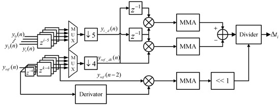
Figure 5.
Proposed architecture of the timing mismatch.
2.3. Derivator Architecture
The traditional derivator is essentially a filter, which consists of the multiplier and the delay register units. Considering that the differentiation effect of the derivator increases with its order, it inevitably consumes a large amount of the aforementioned filters to obtain a sufficiently high order (e.g., [2,6]) and meet the requirements of the design. This paper proposes a simplified structure of the derivator. According to the Lagrange interpolation polynomial, the first-order numerical differentiation can be expressed as [26]
where represents the output of the derivator. By the usage of the Taylor series expansion, the terms , , , and can be effectively expanded. Consequently, (18) can be elegantly reformulated as
where is the derivative of , similarly, and are the fifth-order and seventh-order derivative of , respectively. To enhance the differentiation effect of the derivator, the Richardson extrapolation is employed to construct the higher-order approximation formulas [27]. It estimates the value of the target function by approximation with different step lengths. The first order numerical differential formula from a higher-precision extrapolation can be expressed as
where h represents the sampling step and m represents the number of the iterations. As the number of the iterations increases, the output of the derivator gradually converges to the ideal derivative value. The following expression for the output of the derivator can be derived by the single iteration:
where is expressed as [26]
Subsequently, can be obtained from the Taylor series expansions of and , as is described below.
By comparing (19) and (23), the application of the Richardson extrapolation formula eliminates a certain amount of higher-order derivatives (e.g., ) and enhances the accuracy of the derivator so that the compensation performance can be improved effectively. By substituting (18) and (22) into (21), the expression can be derived as follows:
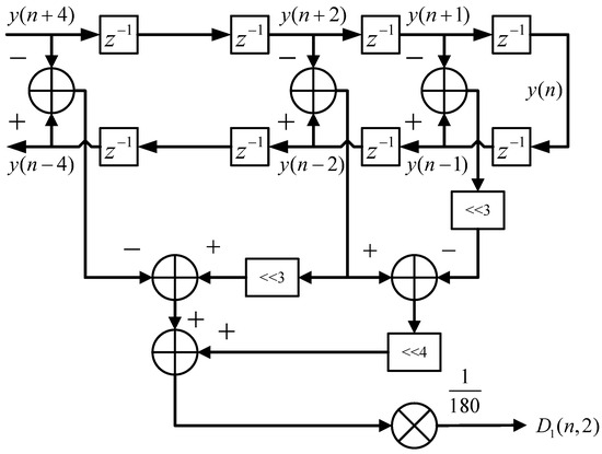
Figure 6.
Proposed architecture of the derivator.
2.4. Derivator Calibration
The linearity of the derivator gradually deteriorates with the increase of the frequency. The non-negligible deviation between the actual and ideal output of the derivative significantly impacts the accuracy of the final compensation and calibration. To compensate for the output deviation at the high-frequency cases, this paper presents a straightforward structure for the calibration of the derivator.
The deviation coefficient of the derivator is solely dependent on the frequency and is unrelated to any channel. Take Channel 3, for example. The sequence after down-sampling is selected. It is aligned with Channel 3, which is written as
Similarly, the sampling sequence that is corresponding to Channel 3 is expressed as
The timing mismatch has been rectified after the compensation with the Taylor series, whereas the derivator still exhibits a frequency-dependent bias coefficient. The corresponding output of the derivator is written as
The expectation of the deviation coefficient can be expressed as
where the expectation of , and are constants on account of the input signal that is band-limited. The calibration architecture of the derivator’s deviation according to (29) is shown in Figure 7.
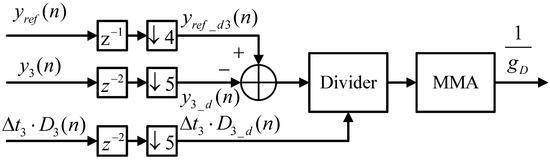
Figure 7.
Proposed architecture of the derivator calibration.
3. Performance Verification
To verify the validity of the technology, the ideal output of the TIADC is systematically generated through the MATLAB. Different timing mismatches are deliberately introduced to the outputs of each channel, and conventional simulations are strictly conducted using the MATLAB environment. The TIADC output signals, deviations across all channels, and the comprehensive calibration architecture are synthesized through the MATLAB 2023a software (Section 3.1). To enhance the validation of the algorithm’s reliability, this paper employs a commercial TIADC from our company as the data source for evaluating the proposed calibration algorithm (Section 3.2). The design of this TIADC is accomplished through the Cadence Virtuoso ic617 software. The effective calibration results also serve to illustrate the reliability of the algorithm.
3.1. Simulation
In this section, a 12-bit 2.4 GS/s four-channel TIADC model with the timing mismatches is constructed to verify the effectiveness of the proposed estimation and the compensation architecture. The sampling frequency of each subchannel is 600 MS/s and the reference channel is 480 MS/s.
Figure 8 shows the spectra of a single-tone signal with a frequency of 0.41f_s. The timing mismatches of the four channels are set as [1‰, −2‰, 3‰, −4‰]. After calibration, the harmonics that are caused by the timing mismatches decrease substantially. The SFDR and SNR increase from 43.81 dB and 43.17 dB to 89.39 dB and 73.50 dB, respectively.
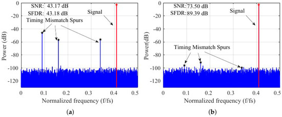
Figure 8.
The spectra of four-channel TIADC output for a single-tone signal input of 0.41 (a) before calibration and (b) after calibration.
Near the boundary of the Nyquist frequency band, the performance of the derivator significantly decreases, which contributes to a substantial drop in the output efficiency (Figure 9a). Compared to the uncalibrated case, the SFDR (SNR) after all-digital timing mismatch calibration without the derivator calibration module increased from 42.85 dB (42.21 dB) to 64.08 dB (62.93 dB), indicating a modest improvement. In contrast, the circuit that introduces the derivator-assisted calibration (Figure 9) raises the SFDR and SNR to 86.96 dB and 73.67 dB, as illustrated in Figure 9b. This brings substantial improvements to derivative calibration.
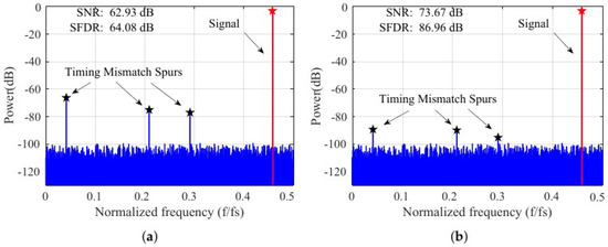
Figure 9.
The spectra of four-channel TIADC output for a single-tone signal input of 0.45 (a) without the derivator calibration and (b) with the derivator calibration.
Figure 10a shows the convergence rate of the timing mismatches. In the actual simulation, the channel rotation method is used to estimate the timing mismatch of each channel. It can be observed that the typical channel switches after approximately 300 samples. The convergence rate of the derivator’s deviation coefficient is shown in Figure 10b, and the convergence samples are approximately 2000. The entire system reaches convergence at approximately 3200 samples. The deviation value is around 1.075 when the is 0.41.
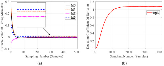
Figure 10.
(a) The convergence rate of the time mismatch error. (b) The convergence rate of the derivator’s deviation coefficient.
Figure 11 shows a significant improvement of the SNR and SFDR under different frequencies. The output performance shows little difference at the low frequencies, but the unmodified structure exhibits a noticeable decrease in performance at the higher frequencies. Moreover, the proposed calibration architecture effectively maintains a stable and high level of the SNR and SFDR in almost the entire Nyquist domain.
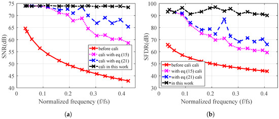
Figure 11.
(a) The SNR and (b) SFDR performance versus different input frequencies.
Figure 12 shows the spectra of the four-channel TIADC output for the multi-tone signal input. The frequencies in Figure 12 are . As can be seen, the spurs from the timing mismatches are effectively suppressed.
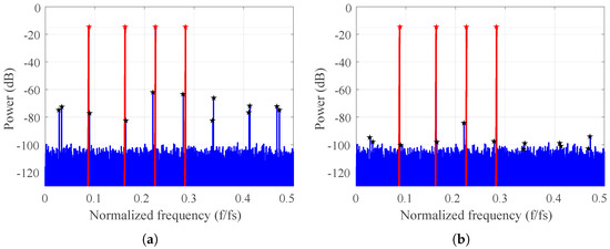
Figure 12.
The spectra of four-channel TIADC output for multi-tone signal input (a) before calibration and (b) after calibration. (The red line signifies the signal, and the blue line signifies the spur).
3.2. Hardware Implementation and Validation
The Verilog design is synthesized to a gate-level netlist by Synopsys Design Compiler (DC) tool that targets the 28 nm technology. The design target of Application Specific Integrated Circuit (ASIC) for the calibration structure is a 12-bit 2.4 GS/s four-channel TIADC. The synthesis result shows that the area of the proposed structure is 0.03 mm2.
The off-chip calibration of a commercial four-channel 12-bit TIADC is performed on the Field Programmable Gate Array (FPGA). The JESD204B interface is also applied for the high-speed signal transmission between the TIADC and the FPGA (VCU108 from Xilinx). The input signal is a 680 MHz sine wave sampled at the frequency of 2 GS/s. Figure 13 shows the test platform that is comprised of the TIADC chip, the clock chip, the Serial Peripheral Interface (SPI) controller, and the FPGA circuit board.
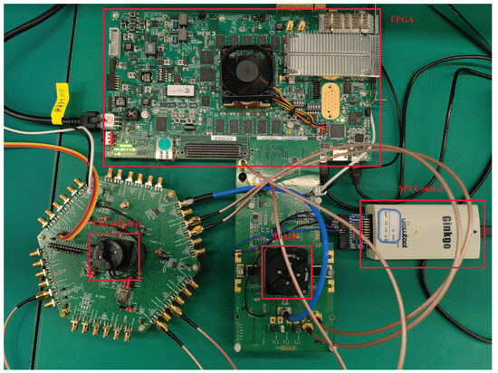
Figure 13.
Experimental setup for the off-chip timing mismatch calibration of the four-channel 2 GS/s TIADC.
Based on the measured data from the 2 GS/s four-channel 12-bits TIADC, the proposed method is used for the off-chip calibration. The input is a single-tone signal with a frequency of 680 MHz (=). Figure 14 shows the off-chip calibration results of the commercial TIADC. It can be seen that the spurs caused by the timing mismatch at the frequencies of 0.09, 0.16 and 0.41 are reduced by 15.09 dB, 26.67 dB, and 12.65 dB, respectively.
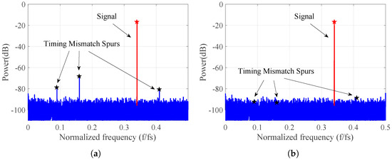
Figure 14.
The off-chip calibration results of the commercial TIADC with the input signal being 680 MHz and the sampling rate being 2 GS/s (a) before calibration and (b) after calibration.
4. Discussion
Table 1 presents the other four works on the all-digital calibration techniques that have been proposed in recent years. Compared to the works of other groups [9,12], this paper presents several significant advantages over the structure with the reference channel, especially in the area consumption and the convergence speed. Compared to Ref. [28], it achieves superior calibration results while maintaining the same level of the accuracy. A significant improvement in calibration performance for the multi-frequency signals is also observed. Compared to Ref. [9], this paper presents a faster convergence speed and wider effective bandwidth. As mentioned, the techniques in Refs. [9,28,29] fail to maintain high-precision output at the high frequencies, which result in a noticeable degradation in the calibration performance. By contrast, the proposed technique solves this issue.

Table 1.
Simulation Performance Comparison.
Relative to the calibration methodologies that have been recently reported by our group, the algorithm in this article shows significant advantages [30,31]. In contrast to the approach in Ref. [30], the feedback architecture is employed to approximate the parameters to the actual values, despite inherent stability concerns. By utilizing a feedforward calibration structure, this paper systematically enhances the stability and improves the entire performance of the calibration process. Relative to the framework in Ref. [31], the proposed structure is characterized by its simplicity, low computational complexity, rapid convergence, and superior performance. The calibration structures in Refs. [30,31] present limited efficacy in the multi-frequency signals calibration, therefore imposing significant constraints on their practical applications. In contrast, the calibration architecture in this paper demonstrates the superior effectiveness in the context of the multi-frequency signals calibration.
Although the inclusion of the reference channel is a notable drawback in comparison to the structure without one, it has been demonstrated to be a strong-expansible and straight structure. The application of the method from Ref. [2] to systems with more than 8 channels generates an exponential increase in hardware resource consumption at both the estimation module for derivative poly-phase filters and the matrix processing unit. However, the proposed structure in this paper can be expanded to accommodate additional channels without incurring any extra hardware consumption within the estimation module.
Given all that, this paper sufficiently validates the effectiveness of the algorithm by the co-simulation of the MATLAB and off-chip measured data. Compared with other literature [9,28,29], the all-digital calibration framework in this paper demonstrates the notable advantages in terms of convergence speed, SFDR, SNR, hardware resource efficiency, and multi-frequency signals calibration. However, the approaches involve additional channels, necessitating a more complex layout, especially concerning the clock tree. In the context of the future endeavors, the forthcoming work will involve the refinement of the existing algorithmic framework, with a particular emphasis on optimizing both the area utilization and the performance. Our calibration methodology is slated for the implementation leveraging an ASIC library.
5. Conclusions
This paper has proposed an all-digital calibration structure of the four-channel TIADC. It effectively addresses the frequency-dependent challenges in compensating for the timing mismatch calibration. Herein, we present a novel estimation method that exploits statistical regularities among individual sub-channels and a reference channel to accurately determine time mismatches. This methodology presents a streamlined architecture with swift convergence rates and robust stability, rendering it exceptionally well-suited for integration into the commercial TIADC. Additionally, an innovative compensation framework we proposed is grounded in the first-order Taylor series expansion. The derivator is refined through the utilization of the Richardson extrapolation, employing the first-order numerical differentiation of the Lagrange interpolation polynomial. The derivator auxiliary circuit is incorporated to improve the accuracy of the derivator and optimize hardware consumption. The simulation that is applied to the 12-bits 2.4 GS/s TIADC demonstrates its effective calibration performance at both the single and the multiple frequencies. The SFDR and SNR at a specific frequency () present an increase of 45.58 dB and 30.33 dB, respectively. Furthermore, the effectiveness of this approach is further substantiated through the off-chip calibration based on the actual TIADC. Moreover, its versatility is manifested in having freedom from the objective restraints, such as the number of channels, input signal amplitude, input frequency, etc. The system possesses the remarkable ability to consistently maintain optimal performance even at high frequencies.
Author Contributions
Conceptualization, W.Z. and Y.D.; methodology, W.Z.; software, W.Z. and L.L.; validation, L.L., L.S., W.X., Y.L., Z.Z. and H.L.; formal analysis, W.Z. and L.S.; investigation, W.Z.; resources, W.Z., Z.Z. and Y.D.; data curation, W.Z.; writing—original draft preparation, W.Z.; writing—review and editing, L.L., L.S. and H.L.; visualization, W.Z., Z.Z. and L.L.; supervision, Y.D.; project administration, Y.D.; funding acquisition, Y.D. and L.L. All authors have read and agreed to the published version of the manuscript.
Funding
This research was funded by the Research Foundation of the Strategic Priority Research Program of the Chinese Academy of Sciences under Grant XDA18030100, and was funded by the Shanghai Sailing Program under Grant 22YF1456400.
Data Availability Statement
Data are contained within the article.
Conflicts of Interest
The authors declare no conflicts of interest.
References
- Black, W.; Hodges, D. Time interleaved converter arrays. IEEE J. Solid-State Circuits 1980, 15, 1022–1029. [Google Scholar] [CrossRef]
- Le Duc, H.; Nguyen, D.M.; Jabbour, C.; Desgreys, P.; Jamin, O.; Tam Nguyen, V. Fully Digital Feedforward Background Calibration of Clock Skews for Sub-Sampling TIADCs Using the Polyphase Decomposition. IEEE Trans. Circuits Syst. Regul. Pap. 2017, 64, 1515–1528. [Google Scholar] [CrossRef]
- Khakpour, A.; Karimian, G. A New Fast Convergent Blind Timing Skew Error Correction Structure for TIADC. IEEE Trans. Circuits Syst. II Express Briefs 2021, 68, 1512–1516. [Google Scholar] [CrossRef]
- Shen, H.; John, D.; Cardiff, B. A Background Calibration for Joint Mismatch in the OFDM System With Time-Interleaved ADC. IEEE Trans. Circuits Syst. II Express Briefs 2022, 69, 3630–3634. [Google Scholar] [CrossRef]
- Miki, T.; Ozeki, T.; Naka, J.I. A 2-GS/s 8-bit Time-Interleaved SAR ADC for Millimeter-Wave Pulsed Radar Baseband SoC. IEEE J. Solid-State Circuits 2017, 52, 2712–2720. [Google Scholar] [CrossRef]
- Lu, Z.; Zhang, W.; Tang, H.; Peng, X. A Novel Two-Stage Timing Mismatch Calibration Technique for Time-Interleaved ADCs. IEEE Trans. Very Large Scale Integr. (VLSI) Syst. 2023, 31, 887–891. [Google Scholar] [CrossRef]
- Benabes, P.; Lelandais-Perrault, C.; Dortz, N.L. Mismatch Calibration Methods for High-Speed Time-Interleaved ADCs. In Proceedings of the 2014 IEEE 12th International New Circuits and Systems Conference (NEWCAS), Trois-Rivieres, QC, Canada, 22–25 June 2014; pp. 49–52. [Google Scholar] [CrossRef]
- Le Duc, H.; Nguyen, D.M.; Jabbour, C.; Graba, T.; Desgreys, P.; Jamin, O.; Nguyen, V.T. Hardware Implementation of All Digital Calibration for Undersampling TIADCs. In Proceedings of the 2015 IEEE International Symposium on Circuits and Systems (ISCAS), Lisbon, Portugal, 24–27 May 2015; pp. 2181–2184. [Google Scholar] [CrossRef]
- Liu, S.; Zhao, L.; Li, S. A Novel All-Digital Calibration Method for Timing Mismatch in Time-Interleaved ADC Based on Modulation Matrix. IEEE Trans. Circuits Syst. Regul. Pap. 2022, 69, 2955–2967. [Google Scholar] [CrossRef]
- Qiu, Y.; Liu, Y.J.; Zhou, J.; Zhang, G.; Chen, D.; Du, N. All-Digital Blind Background Calibration Technique for Any Channel Time-Interleaved ADC. IEEE Trans. Circuits Syst. Regul. Pap. 2018, 65, 2503–2514. [Google Scholar] [CrossRef]
- Xiong, W.; Zhang, Z.; Lang, L.; Dong, Y. A Novel Fully Digital Feedforward Background Calibration Technique for Timing Mismatch in M-Channel Time-Interleaved ADCs. Electronics 2023, 12, 1965. [Google Scholar] [CrossRef]
- Chen, H.; Wang, J.; Wang, L.; Li, L.; Deng, H.; Meng, X.; Yin, Y. Fully Digital Calibration Technique for Channel Mismatch of TIADC at Any Frequency. Ieice Trans. Electron. 2023, E106.C, 84–92. [Google Scholar] [CrossRef]
- El-Chammas, M.; Murmann, B. A 12-GS/s 81-mW 5-bit time-interleaved flash ADC with background timing skew calibration. In Proceedings of the 2010 Symposium on VLSI Circuits, Honolulu, HI, USA, 16–18 June 2010; pp. 157–158. [Google Scholar] [CrossRef]
- Zhou, Y.; Xu, B.; Chiu, Y. A 12-b 1-GS/s 31.5-mW Time-Interleaved SAR ADC with Analog HPF-Assisted Skew Calibration and Randomly Sampling Reference ADC. IEEE J. Solid-State Circuits 2019, 54, 2207–2218. [Google Scholar] [CrossRef]
- Liu, W.; Chang, Y.; Hsien, S.K.; Chen, B.W.; Lee, Y.P.; Chen, W.T.; Yang, T.Y.; Ma, G.K.; Chiu, Y. A 600 MS/s 30 mW 0.13 µm CMOS ADC array achieving over 60 dB SFDR with adaptive digital equalization. In Proceedings of the 2009 IEEE International Solid-State Circuits Conference—Digest of Technical Papers, San Francisco, CA, USA, 8–12 February 2009; pp. 82–83,83a. [Google Scholar] [CrossRef]
- Chen, H.; Yin, Y.; Liu, T.; Gan, L.; Xiao, R.; Yan, H.; Deng, H. A split-based fully digital feedforward background calibration technique for timing mismatch in TIADC. Integration 2020, 71, 105–114. [Google Scholar] [CrossRef]
- Yin, Y.; Sun, K.; Chen, H.; Wang, X.; Liu, L.; Deng, H.; Meng, X.; Li, K.; Wang, Z. Calibration of timing mismatch in TIADC based on monotonicity detecting of sampled data. IEICE Electron. Express 2020, 17, 20190699. [Google Scholar] [CrossRef]
- Shi, C.; Xie, X.; Zhang, X.; Yu, L. Calibration of timing mismatch for TIADC based on error table and fractional delay filter. J. Phys. Conf. Ser. 2023, 2525, 012001. [Google Scholar] [CrossRef]
- Qiu, L.; Tang, K.; Zheng, Y.; Siek, L.; Zhu, Y.; U, S.P. A 16-mW 1-GS/s with 49.6-dB SNDR TI-SAR ADC for Software-Defined Radio in 65-nm CMOS. IEEE Trans. Very Large Scale Integr. (VLSI) Syst. 2018, 26, 572–583. [Google Scholar] [CrossRef]
- Peng, X.; Zhang, Y.; Wang, W.; Yang, S. Broadband Mismatch Calibration for Time-Interleaved ADC Based on Linear Frequency Modulated Signal. IEEE Trans. Circuits Syst. Regul. Pap. 2021, 68, 3621–3630. [Google Scholar] [CrossRef]
- Liu, Y.; Zhang, Z.; Xiong, W.; Sun, L.; Lang, L.; Wu, X.; Dong, Y. An improved wide-range, low-complexity, fully-parallel digital background timing mismatch calibration method for dual-channel TIADC based on perfect reconstruction filter bank. AEU-Int. J. Electron. Commun. 2023, 171, 154910. [Google Scholar] [CrossRef]
- Yin, M.; Ye, Z. First Order Statistic Based Fast Blind Calibration of Time Skews for Time-Interleaved ADCs. IEEE Trans. Circuits Syst. II Express Briefs 2020, 67, 162–166. [Google Scholar] [CrossRef]
- Chen, S.; Wang, L.; Zhang, H.; Murugesu, R.; Dunwell, D.; Carusone, A.C. All-Digital Calibration of Timing Mismatch Error in Time-Interleaved Analog-to-Digital Converters. IEEE Trans. Very Large Scale Integr. (VLSI) Syst. 2017, 25, 2552–2560. [Google Scholar] [CrossRef]
- Khalil, R.; Louërat, M.M.; Petigny, R.; Gicquel, H. Background offset and gain calibration for time-interleaved ADC using digital sinusoidal calibration signal. In Proceedings of the 2012 International Conference on Synthesis, Modeling, Analysis and Simulation Methods and Applications to Circuit Design (SMACD), Seville, Spain, 19–21 September 2012; pp. 273–276. [Google Scholar] [CrossRef]
- Pei, S.C.; Shyu, J.J. Eigenfilter design of higher-order digital differentiators. IEEE Trans. Acoust. Speech Signal Process. 1989, 37, 505–511. [Google Scholar] [CrossRef]
- Dubeau, F. A remark on Richardson’s extrapolation process and numerical differentiation formulae. J. Comput. Phys. X 2019, 2, 100017. [Google Scholar] [CrossRef]
- Batiha, I.M.; Alshorm, S.; Ouannas, A.; Momani, S.; Ababneh, O.Y.; Albdareen, M. Modified Three-Point Fractional Formulas with Richardson Extrapolation. Mathematics 2022, 10, 3489. [Google Scholar] [CrossRef]
- Liu, S.; Li, S.; Sun, X. A Low-Complexity Timing Skew Mismatch Calibration Method for Time-Interleaved ADCs. In Proceedings of the 2023 IEEE 15th International Conference on ASIC (ASICON), Nanjing, China, 24–27 October 2023; pp. 1–4. [Google Scholar] [CrossRef]
- Gu, Y.; Feng, X.; Chi, R.; Wu, J.; Chen, Y. A Novel Autocorrelation Combined MM-CDR Time-Interleaved ADC Timing Calibration in 28 nm CMOS Technology. Electronics 2022, 11, 3198. [Google Scholar] [CrossRef]
- Kang, T.; Zhang, Z.; Xiong, W.; Sun, L.; Liu, Y.; Zhong, W.; Lang, L.; Shan, Y.; Dong, Y. A Digital Timing-Mismatch Calibration Technique for Time-Interleaved ADCs Based on a Coordinate Rotational Digital Computer Algorithm. Electronics 2023, 12, 1319. [Google Scholar] [CrossRef]
- Sun, L.; Lang, L.; Zhong, W.; Liu, H.; Dong, Y. A Fast Mismatch Calibration Method Based on Frequency Domain Orthogonal Decomposition for Time-Interleaved Analog-to-Digital Converters. Electronics 2023, 12, 5042. [Google Scholar] [CrossRef]
Disclaimer/Publisher’s Note: The statements, opinions and data contained in all publications are solely those of the individual author(s) and contributor(s) and not of MDPI and/or the editor(s). MDPI and/or the editor(s) disclaim responsibility for any injury to people or property resulting from any ideas, methods, instructions or products referred to in the content. |
© 2024 by the authors. Licensee MDPI, Basel, Switzerland. This article is an open access article distributed under the terms and conditions of the Creative Commons Attribution (CC BY) license (https://creativecommons.org/licenses/by/4.0/).