Abstract
In order to improve image recognition technologies in an IoT environment, we propose a data reduction scheme for a feature-extractable CMOS image sensor and present simulation results for object recognition using feature data. We evaluated the accuracy of the simulated feature data in object recognition based on YOLOX trained with a feature dataset. According to our simulation results, the obtained object recognition accuracy was with the large-scale COCO dataset, even though the amount of data was reduced by compared to conventional RGB color images. When the dataset was replaced with the RAISE RAW image dataset for more accurate simulation, the object recognition accuracy improved to . Furthermore, the feature-extractable CMOS image sensor can switch its operation mode between RGB color image mode and feature data mode. When the trigger for switching from feature data mode to RGB color image mode was set to the detection of a large-sized person, the feature data achieved an accuracy of with the COCO dataset.
1. Introduction
In the present IoT age, information from a vast number of sensors in the physical space is analyzed by means of artificial intelligence (AI) in cyberspace before being fed back to the physical space [1]. In order to achieve high accuracy in image recognition, we use deep neural network (DNN) models [2,3,4,5,6,7] trained with large-scale datasets [8,9,10]. However, recognition systems composed of sensors and DNNs consume a large amount of power; this must be reduced if we are to create a more sustainable society. Besides research on AI algorithms to reduce redundant computations [11,12,13], CMOS image sensors for AI applications have also attracted attention. Since conventional image sensors often output redundant data that AI removes in feature extraction, image sensors that can output lightweight feature data are one way for us to reduce the power consumption of image recognition systems and save storage space for vast amounts of imaging data [14,15,16,17,18]. A log-gradient QVGA image sensor [14] outputs feature data for histograms of oriented gradients (HOGs). However, conventional RGB color photographic images cannot be output because the readout circuit is specific to HOG feature extraction. An analog convolution image sensor [15] can output both grayscale photographic images and feature data, but its large pixels due to an in-pixel capacitor that enables the multiply–accumulate (MAC) operation introduce concerns regarding light sensitivity and chip cost. Event-based vision sensors (EVSs) [18] that suppress temporal redundancy enable operation in the high dynamic range using lightweight feature data. However, EVSs cannot detect stationary objects because small changes in luminance (those that fall below a preset threshold [19,20]) cannot be output to suppress redundancy. The pixel size is also large due to an in-pixel circuit that detects temporal luminance changes.
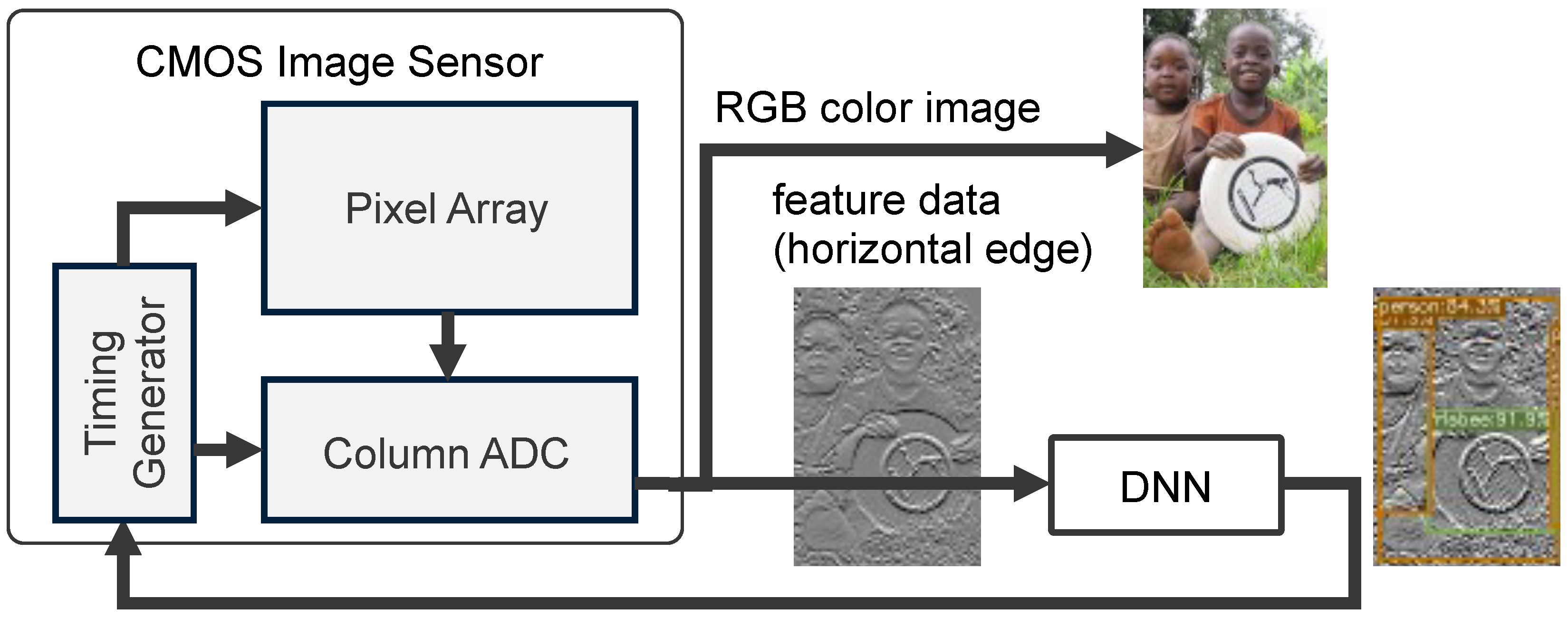
Our research group has proposed a CMOS image sensor that can generates both RGB color images and feature data using a pixel with a schematic that is compatible with conventional CMOS image sensors [21]. Figure 1 shows a conceptual diagram of an object recognition system with a feature-extractable CMOS image sensor. In using lightweight feature data that are recognized by a DNN, the amount of power consumed by image recognition systems can be reduced in terms of optimizing energy efficiency, data storage, and network load. When a given object is detected in the feature data, the mode of the image sensor shifts from operation mode to RGB color image mode so that it can be viewed by humans and/or subjected to further analysis by the DNN. Our research target is compared with other approaches, as shown in Table 1. We focus on a feature-extractable image sensor, where the feature data consist of simple horizontal edges, and the sensor is compatible with low-cost RGB color image sensors composed of small-sized pixels.
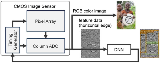
Figure 1.
Object recognition system with a feature-extractable CMOS image sensor [8].

Table 1.
Comparison of our targets with other approaches.
In this paper, we propose a data reduction scheme for feature data extracted from a CMOS image sensor and present the results of an experiment that aimed to simulate object recognition using feature data. The amount of feature data can be reduced by converting RGB images to grayscale images, extracting edges, signal binning, and aggressive quantization, all of which take place in the CMOS image sensor. We evaluated the accuracy of the feature data for the purpose of object recognition using YOLOX [22] trained with a simulated feature dataset. YOLOX, proposed in 2021, is part of the YOLO (You Only Look Once) series, designed for object detection in images. The on-chip data reduction method is proposed in Section 2. Section 3 presents object recognition accuracy based on the COCO dataset [8], which is a large-scale dataset composed of 200 K labeled images and 80 object categories. Section 4 discusses how the dataset was replaced with the RAISE RAW image dataset in order to simulate the proposed on-chip processing more accurately. While the COCO dataset consists of demosaiced and lossy-compressed RGB channels, the RAISE dataset consists of uncompressed RAW images that are consistent with the output of image sensors. Section 5 summarizes this paper.
Updates from the Conference Proceeding
A conference proceeding version of this paper appeared in the International Workshop on Advanced Imaging Technology (IWAIT) 2024 [23], and this extended version contains the following new contents:
- A comparison of our methods with other approaches (Table 1);
- Examples of feature data after aggressive quantization to 3-bit resolution [8] (Figure 8);
- The dependence of object recognition accuracy on quantized bit resolution (Figure 10);
- The dependence of object recognition accuracy on noise introduced during feature extraction (Figure 11);
- The dependence of object recognition accuracy on the size of the objects (Table 4);
- Simulation results with RAISE RAW image dataset (Section 4).
2. Proposed CMOS Image Sensor
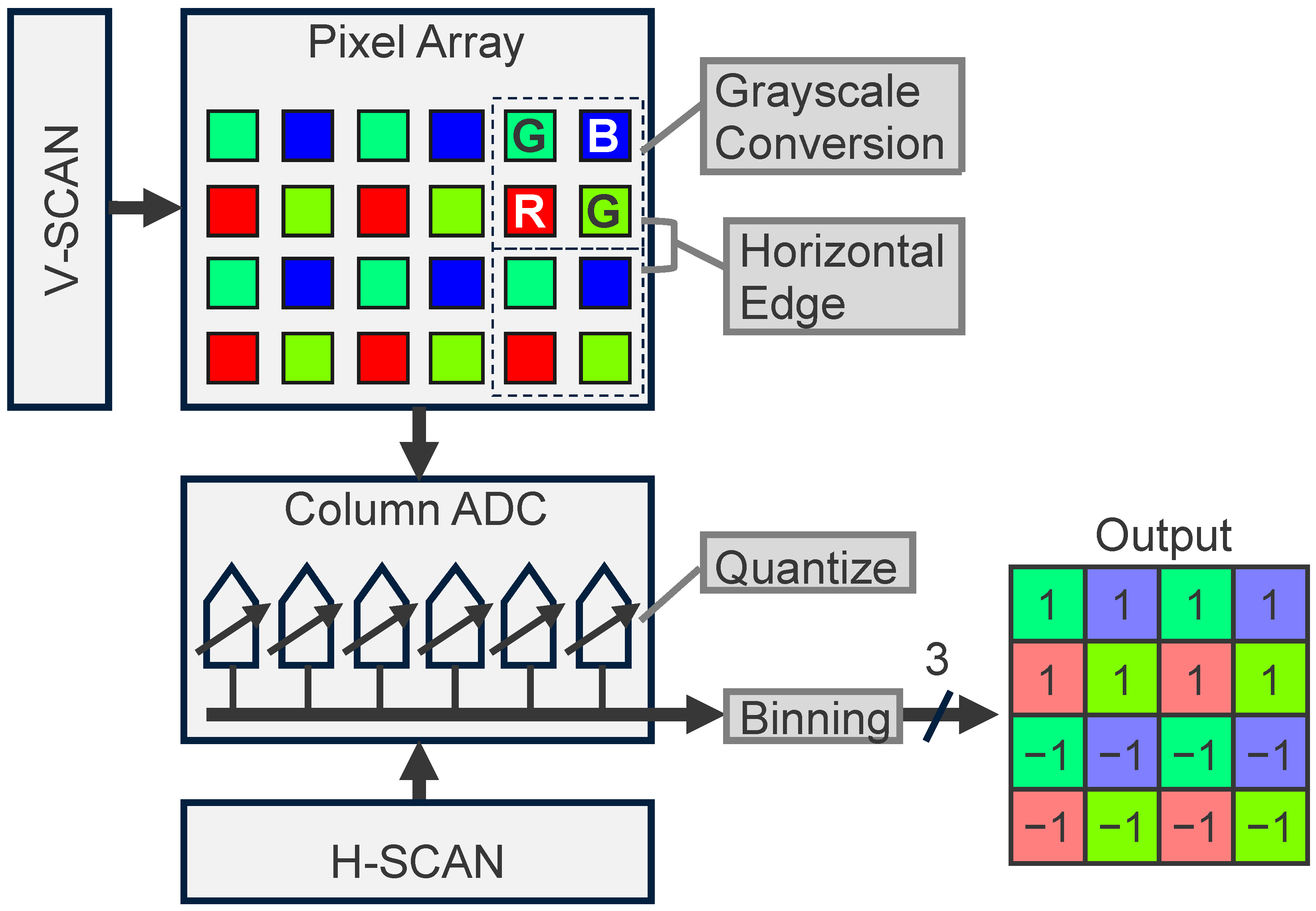
Figure 2 shows an overview of the proposed CMOS image sensor, which can output both RGB color images and feature data. An RGB color image is read out by pixel-by-pixel architecture at an 8-bit resolution, much like conventional CMOS image sensors. Feature data are extracted as follows. Due to its four-shared pixel structure, the RGB color pixel signal is converted to a grayscale signal given by , in which photoelectrons accumulated in a Bayer array are read out simultaneously, thereby reducing the spatial resolution to . The horizontal edge of the grayscale signal is then extracted by subtracting vertically adjacent Bayer array cells instead of the correlated double-sampling of a single pixel; this reduces the spatial resolution to . The analog feature output from the pixel array is quantized with the column of parallel ADC, which is switched to low-bit resolution mode (an example of which is 3-bit mode); this reduces the bit resolution to . The horizontally adjacent pixel signal is then binned, reducing the spatial resolution to . Therefore, the output data size of the feature data is reduced to only (=3/128) compared to that of the RGB color image. For the case of the 2 Mpixel 60 fps CMOS image sensor, the RGB color image, whose data rate is roughly given by Gbps, is typically transferred in MIPI D-PHY HS (high-speed) mode. On the other hand, the feature data whose data rate is only Mbps at 15 fps can be transferred in MIPI D-PHY LP (low-power) mode. A circuit diagram of the proposed CMOS image sensor, in which the grayscale conversion, horizontal edge extraction, quantization, and binning take place, is described in the following section.

Figure 2.
Processing pipeline of feature data extraction in a CMOS image sensor which can output both RGB color images and feature data.
2.1. Grayscale Conversion and Horizontal Edge Extraction
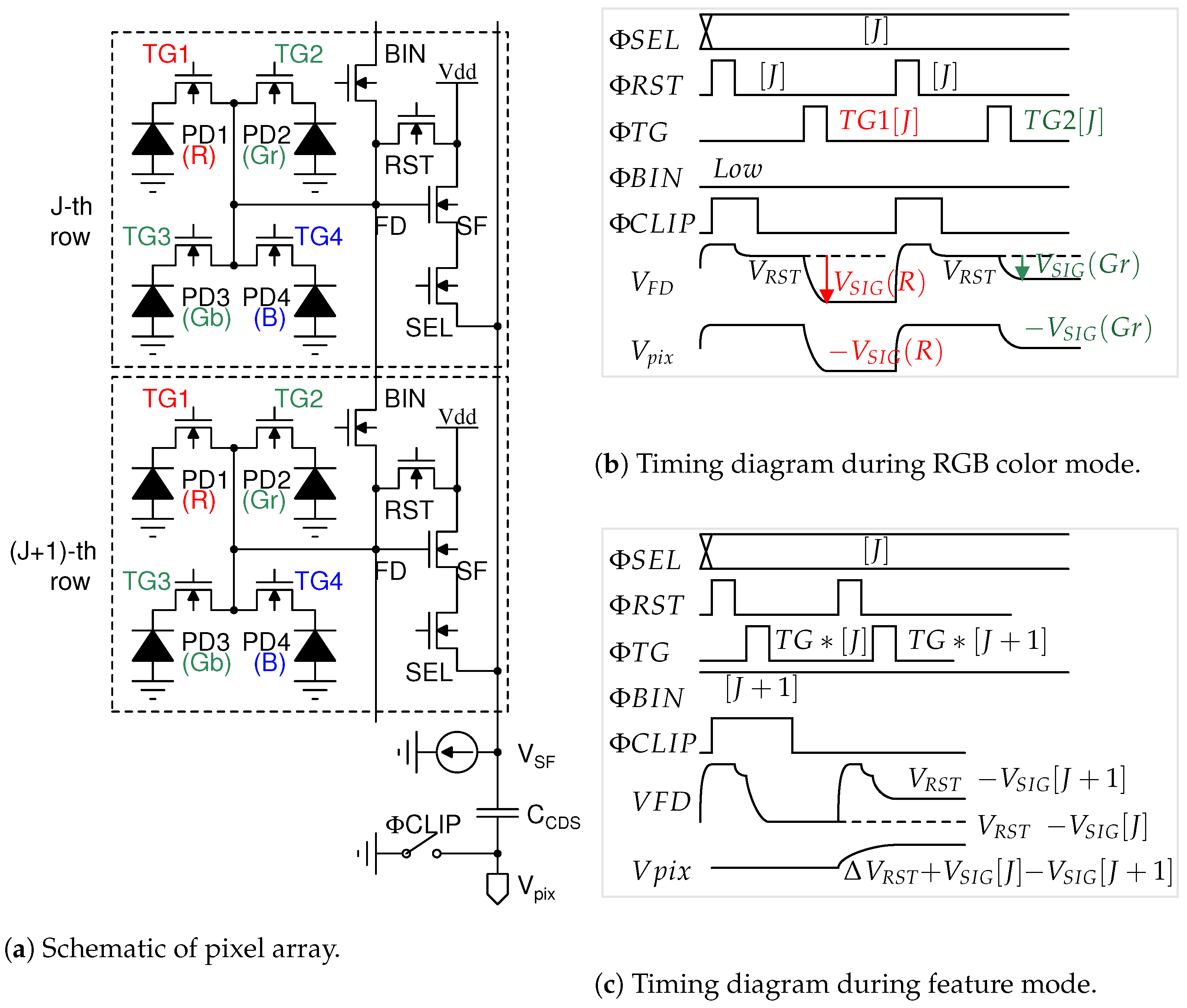
Figure 3 shows a schematic and timing diagram of the image sensor pixel, which consists of a conventional four-shared pixel array, as shown in Figure 3a. During the RGB color mode shown in Figure 3b, the reset voltage of the FD node is read out and followed by signal voltage, which is charged by photoelectrons accumulated in a red photodiode PD1. The voltage difference is output through the capacitor in order to remove the FD reset noise. In the feature mode shown in Figure 3c, photoelectrons that are accumulated photodiodes PD1, PD2, PD3, and PD4 in the J-th row are transferred to the FD nodes shorted with a BIN transistor, in which the FD node voltage represents the grayscale signal given by . The (J + 1)-th row grayscale signal is then read out. The difference in voltage between the grayscale signals in the J-th row and the (J + 1)-th row is output through the capacitor , which represents the horizontal edge. The J-th and (J + 1)-th row signals are transferred to through the same SF and SEL transistors in the J-th row to remove the offset voltage caused by mismatches in the source follower transistors between the J-th and (J + 1)-th rows. On the other hand, since the FD reset noise is not canceled due to the pulsing twice, the FD reset noise, given by , is imposed upon the grayscale signal, which is utilized in the simulation of object recognition.

Figure 3.
Overview of proposed CMOS image sensor pixel.
The grayscale signal is typically calculated using formulas such as , , and other algorithms. The impact of these grayscale algorithms on image recognition performance with machine learning is not negligible [24] on image signal processing. However, in this paper, the grayscale signal given by in the pixel array is proposed for image recognition with the DNN. In the grayscale signal, the photoelectrons accumulated in each photodiode (PD) of the “RGGB” Bayer array are read out simultaneously without requiring any additional circuit. Furthermore, the number of electrons in the signal is higher than that in the signal. As a result, a higher signal-to-noise (S/N) ratio is achieved, leading to improved recognition accuracy.
2.2. Quantization
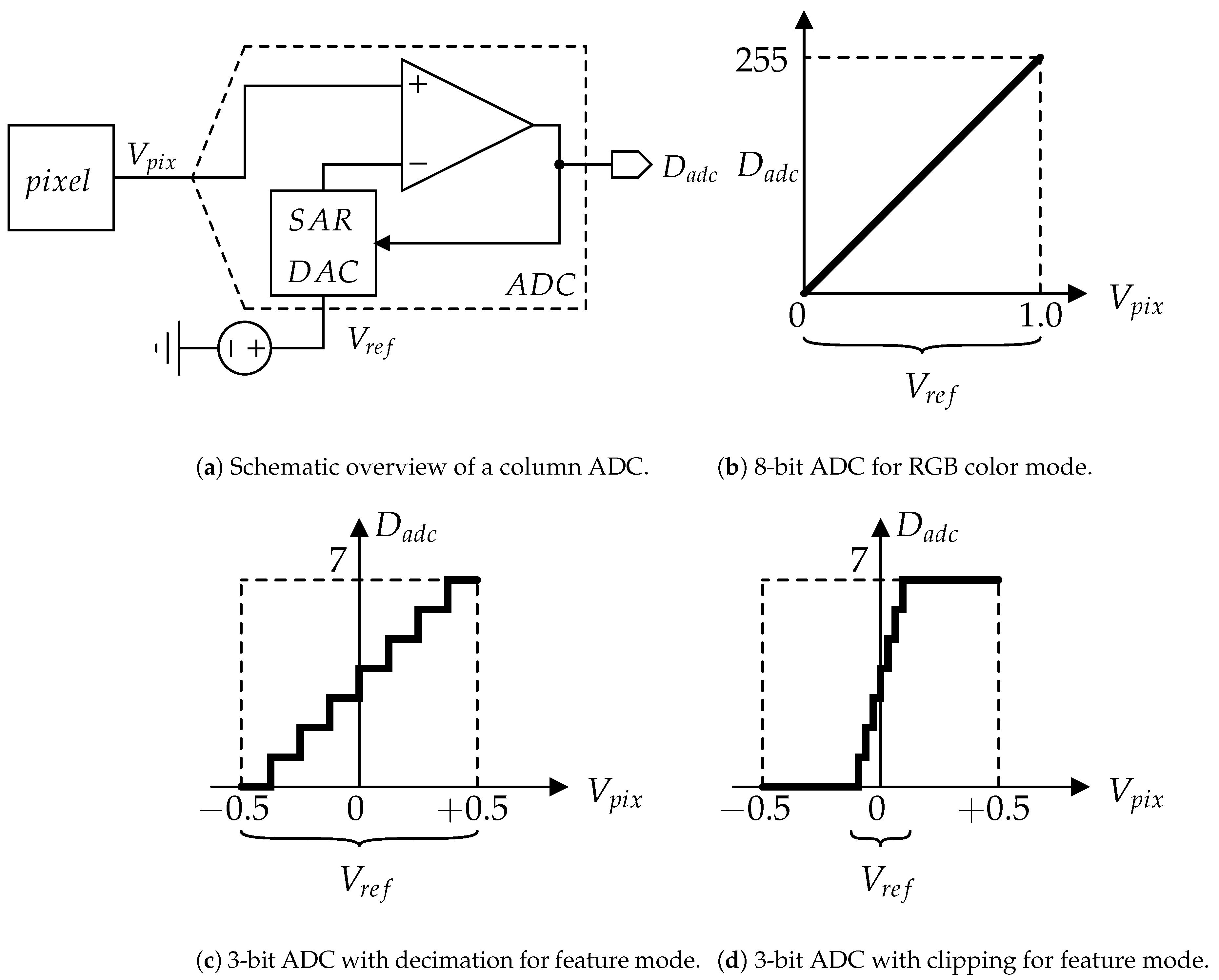
The analog feature output from the pixel array is aggressively quantized with the ADC. While the RGB color image is quantized to an 8-bit digital signal, the feature data are quantized to low-bit resolution. As shown in Figure 4a, the pixel’s output signal is processed with a successive approximation register (SAR) ADC, which implements a binary search algorithm [21]. In the RGB color mode, eight comparisons between the and SAR-DAC output take place, in which the reference voltage range is V, are used to convert the V range of into the 8-bit digital output , as shown in Figure 4b. In the feature mode, the pixel output is aggressively quantized by clipping and/or decimation. Herein, let us suppose that the feature data are quantized to the 3-bit form. In the decimation shown in Figure 4c, the number of comparisons is changed to three. In the clipping shown in Figure 4d, the range is also changed to mV (=).
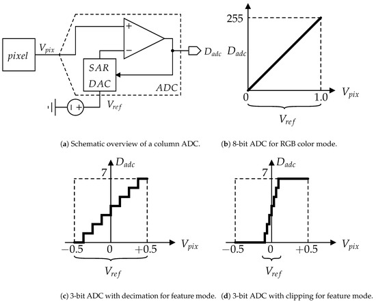
Figure 4.
Overview of quantization in a CMOS image sensor.
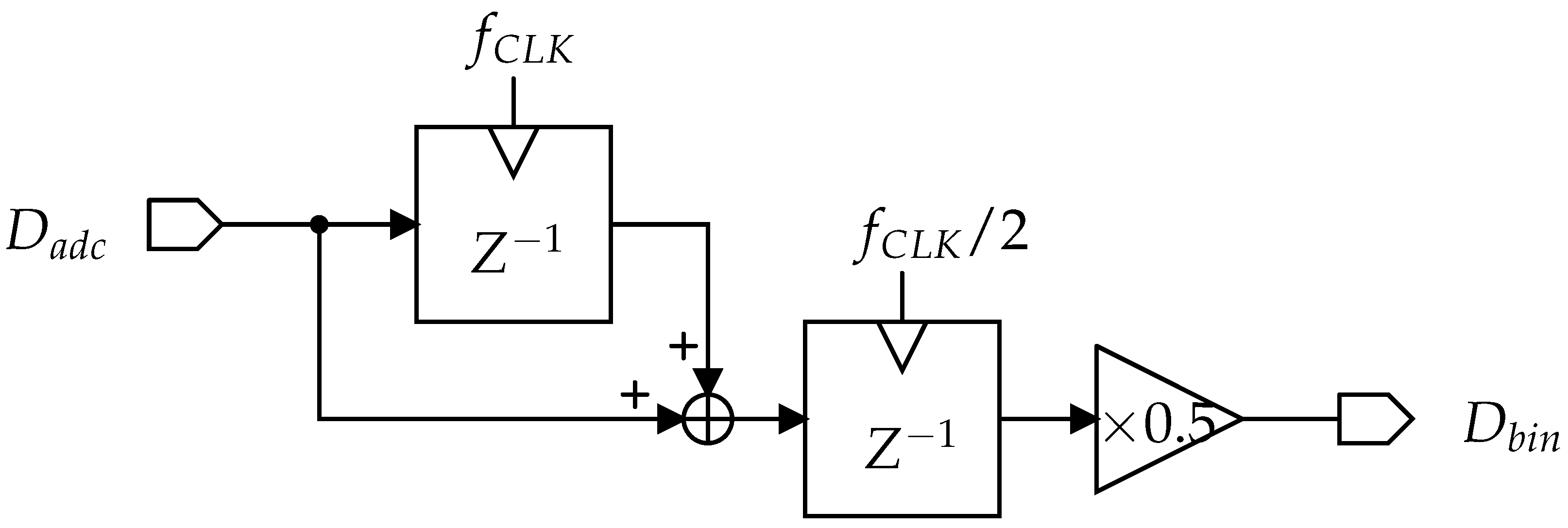
2.3. Horizontal Binning
The spatial resolution of the feature data is further reduced by the binning in the horizontal readout of the column-parallel ADC output. Figure 5 shows the binning circuit, to which the output of the column-parallel ADC is transferred sequentially, column-by-column. For the I-th and -th column feature data, the binning circuit output is given by , which represents averaged feature data. With additional delay and sum blocks, the feature data can be averaged into three columns. It is worth noting that binning at the ADC input is also useful for horizontal binning. In this case, half of the ADC columns operate for quantization, while the other half can remain in standby mode to save power consumption.

Figure 5.
Schematic of horizontal binning in a CMOS image sensor.
3. Simulation Results for the COCO Dataset
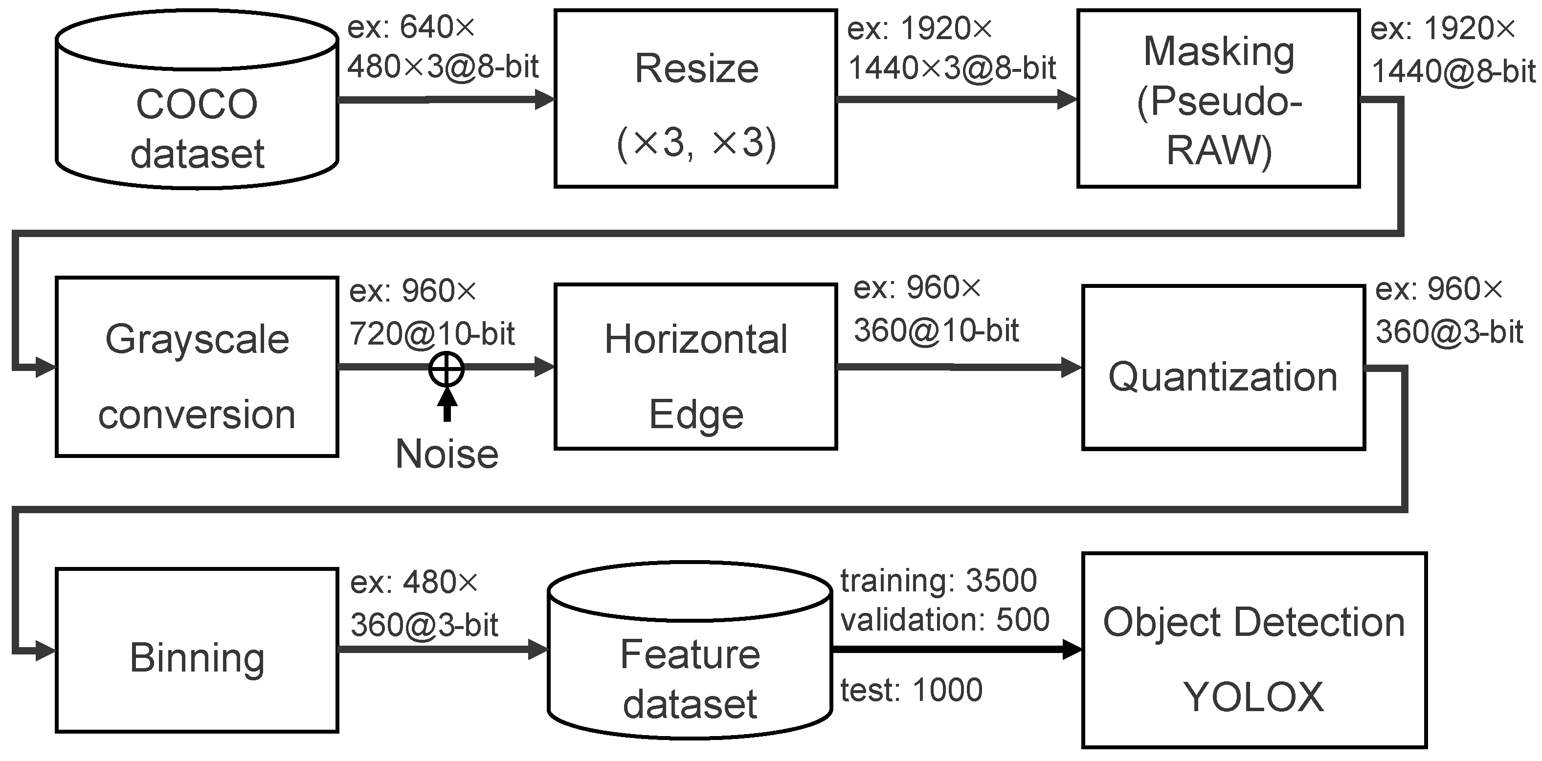
In order to accurately simulate image recognition accuracy with the proposed feature-extractable CMOS image sensor, the RGB color images of the COCO dataset are converted into feature data, as shown in Figure 6. Since the image size in the majority of the COCO dataset is pixel, the data are first resized to around 2 Mpixels, which is the size required of the proposed CMOS image sensor.
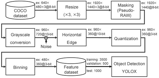
Figure 6.
Processing flow used to generate the COCO feature dataset.
Furthermore, the three-channel RGB color image is masked to mimic the pixel output of a one-channel RAW image, where each pixel value is derived according to a Bayer filter arrangement. Grayscale conversion, FD reset noise addition, horizontal edge extraction, aggressive quantization, and binning are then performed to generate the feature dataset. The feature dataset contains 3500 training images, 500 validation images, and 1000 test images. The FD reset noise is supposed to be less than at 10-bit resolution, since the value of the FD nodes that are shortened with BIN transistor is supposed to be 4 fF. The effect of each stage of on-chip processing on object recognition accuracy is described in the following section.
3.1. Grayscale Conversion and Horizontal Edge Extraction
The effect of grayscale conversion and horizontal edge extraction on object recognition accuracy is summarized in Table 2, where mean average precision (mAP) at the intersection over union (IoU) is utilized as a metric of recognition accuracy. As a reference, the YOLOX pretrained with the RGB color image achieved accuracy for an RGB color test image. Even though the YOLOX pretrained with the feature data degrades the accuracy by around , the amount of data can be drastically reduced. The feature data subjected to grayscale conversion and edge extraction achieved accuracy, and the amount of data required was reduced to only .
Table 2.
Object recognition accuracy and data required for grayscale conversion and horizontal edge extraction.
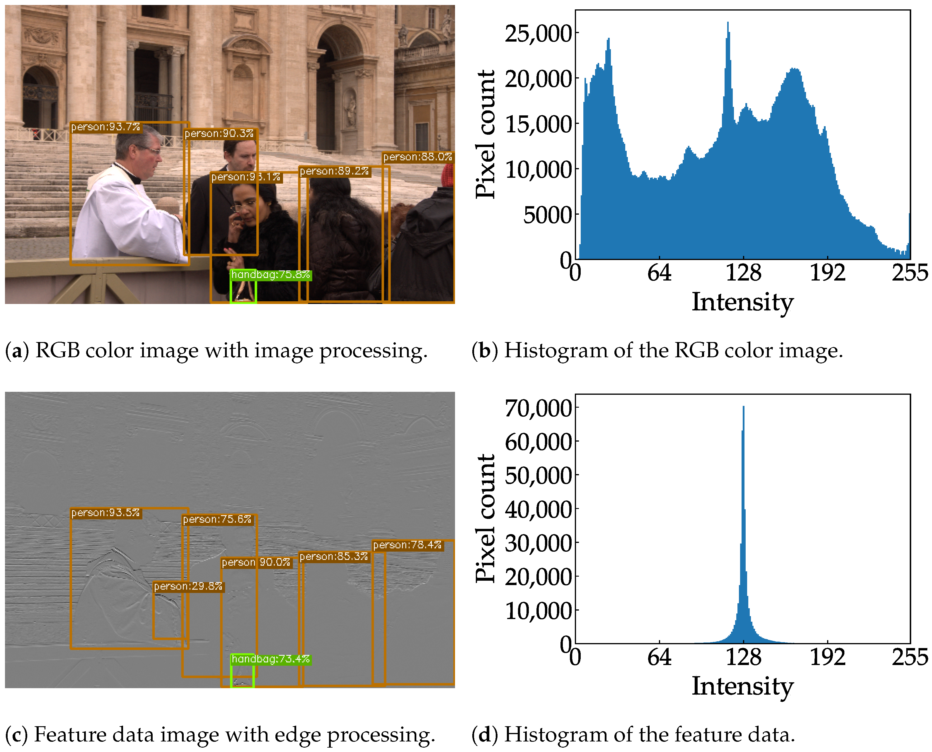
Examples of RGB color images and feature data are shown in Figure 7, where the color image and feature data are resized to the same aspect ratio for the sake of visibility. Figure 7a,b show an 8-bit RGB color image and the distribution of the corresponding histogram, respectively. As shown in Figure 7c, the rounded shape of a Frisbee is still visible in the feature data; this is because a diagonal edge incorporates a horizontal vector. Compared to the histogram of the RGB color image, the histogram of the feature data is narrower and more centered, as shown in Figure 7d. A pixel with an intensity above 128 indicates a positive gradient, while a pixel with an intensity below 128 indicates a negative gradient. A pixel with an intensity of 128 indicates no gradient. This narrow histogram suggests that the feature data are suitable for clipping and can be aggressively quantized.
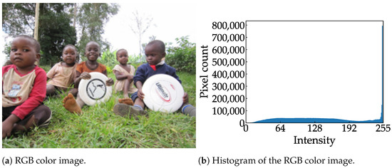
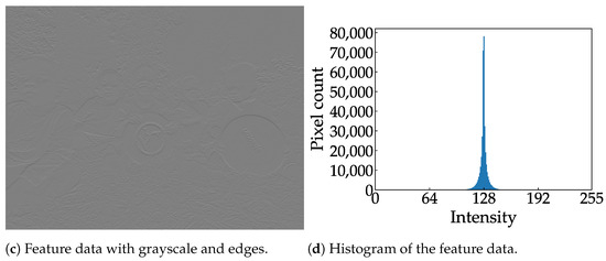
Figure 7.
Sample images from the COCO dataset [8] and their respective histograms.
3.2. Horizontal Binning
The effect of horizontal binning on object recognition accuracy is summarized in Table 3, where the feature data remain in 8-bit resolution. When the binning was applied to two-column feature data (2-Bin), the accuracy was maintained at ; nevertheless, the amount of data was reduced to only . However, the accuracy degraded to after binning was applied to the three-column feature data (3-Bin). Since the accuracy gradually degrades as the number of binning columns increases, aggressive quantization was applied only to the 2-Bin feature data.
Table 3.
Effect of horizontal binning on object recognition accuracy on the COCO dataset.
3.3. Quantization
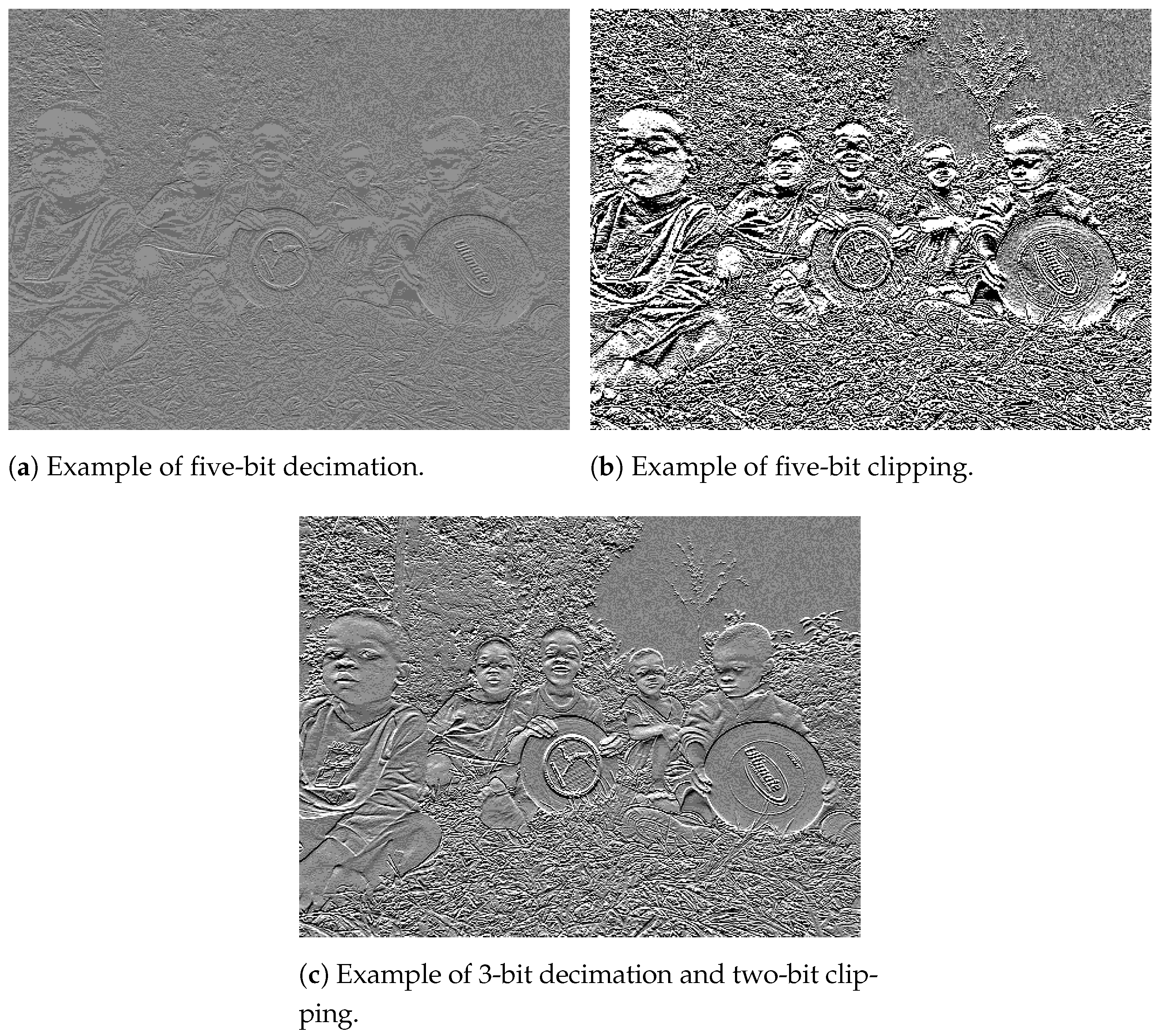
Figure 8 shows examples of feature data after aggressive quantization to 3-bit resolution. When the feature data are quantized only using decimation, the contrast is low, and the visibility of the edge of objects is poor, as shown in Figure 8a. When the feature data are quantized using only clipping, the noise is excessively enhanced, as shown in Figure 8b. When the feature data are quantized with a combination of decimation and clipping, the visibility of object edges is improved, as shown in Figure 8c.
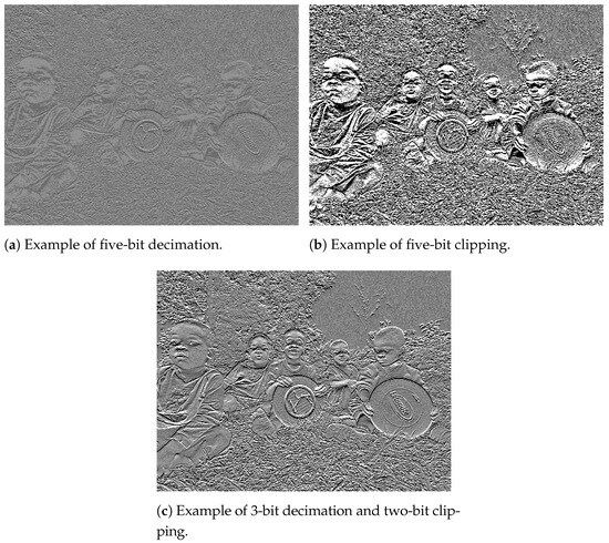
Figure 8.
Examples of feature data after aggressive quantization to 3-bit resolution [8].
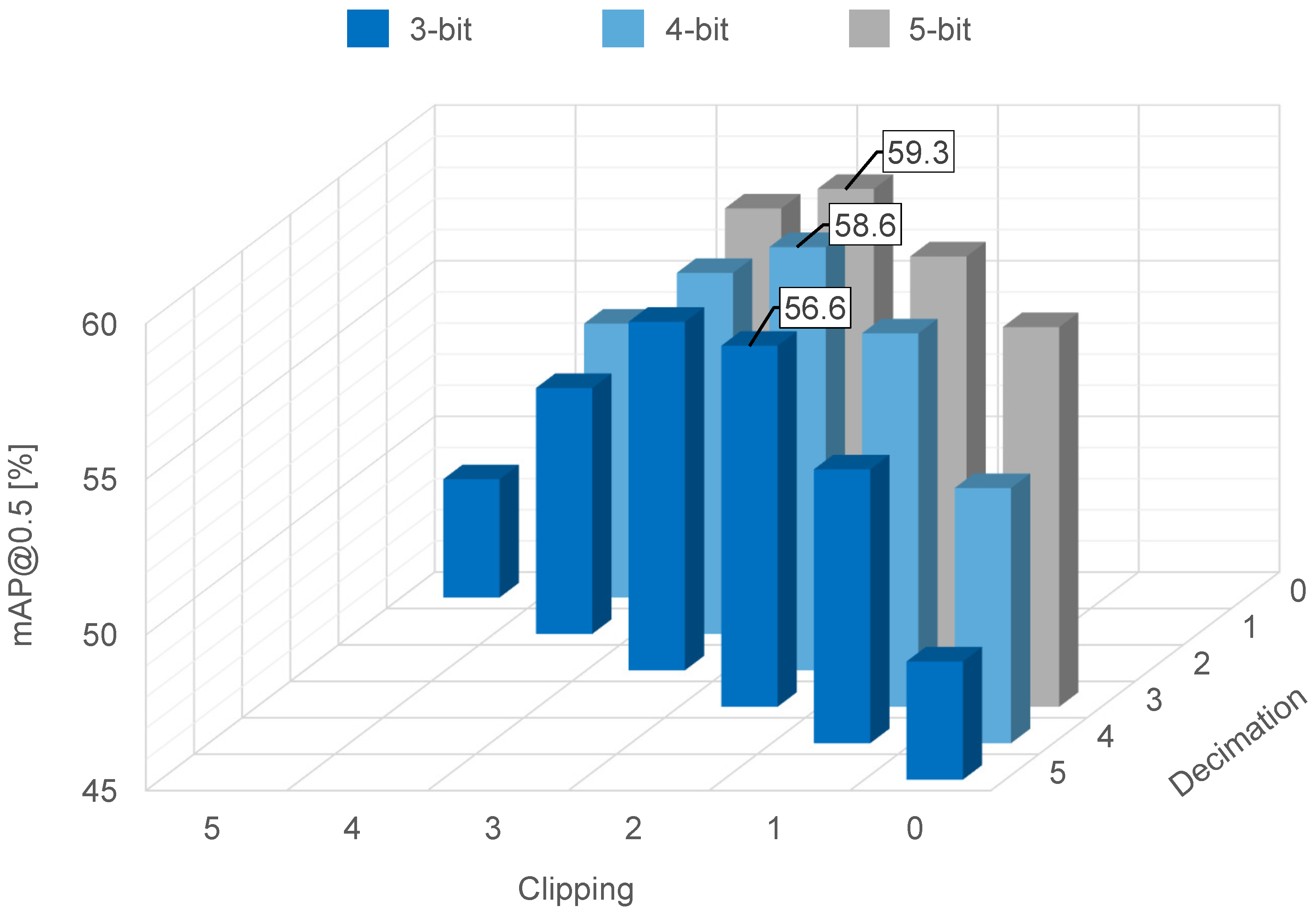
The effect of the quantization on object recognition accuracy is summarized in Figure 9, where the feature data are quantized to three-, four- or five-bit resolution via decimation, clipping, or a combination of decimation and clipping. When a combination of one-bit decimation and two-bit clipping was used, the feature data had a five-bit resolution and achieved accuracy. When a combination of two-bit decimation and two-bit clipping was used, the feature data had a four-bit resolution and achieved accuracy. When a combination of 3-bit decimation and two-bit clipping was used, the feature data had a 3-bit resolution and achieved accuracy. From these results, we were able to confirm superior recognition accuracy after two-bit clipping in all cases (with feature data quantized to three-, four-, and five-bit resolution). This is because an appropriate number of clipping bits improves the visibility of objects’ edges, as shown in Figure 8.

Figure 9.
Object recognition accuracy on the COCO dataset for thee-, four-, and five-bit resolution.
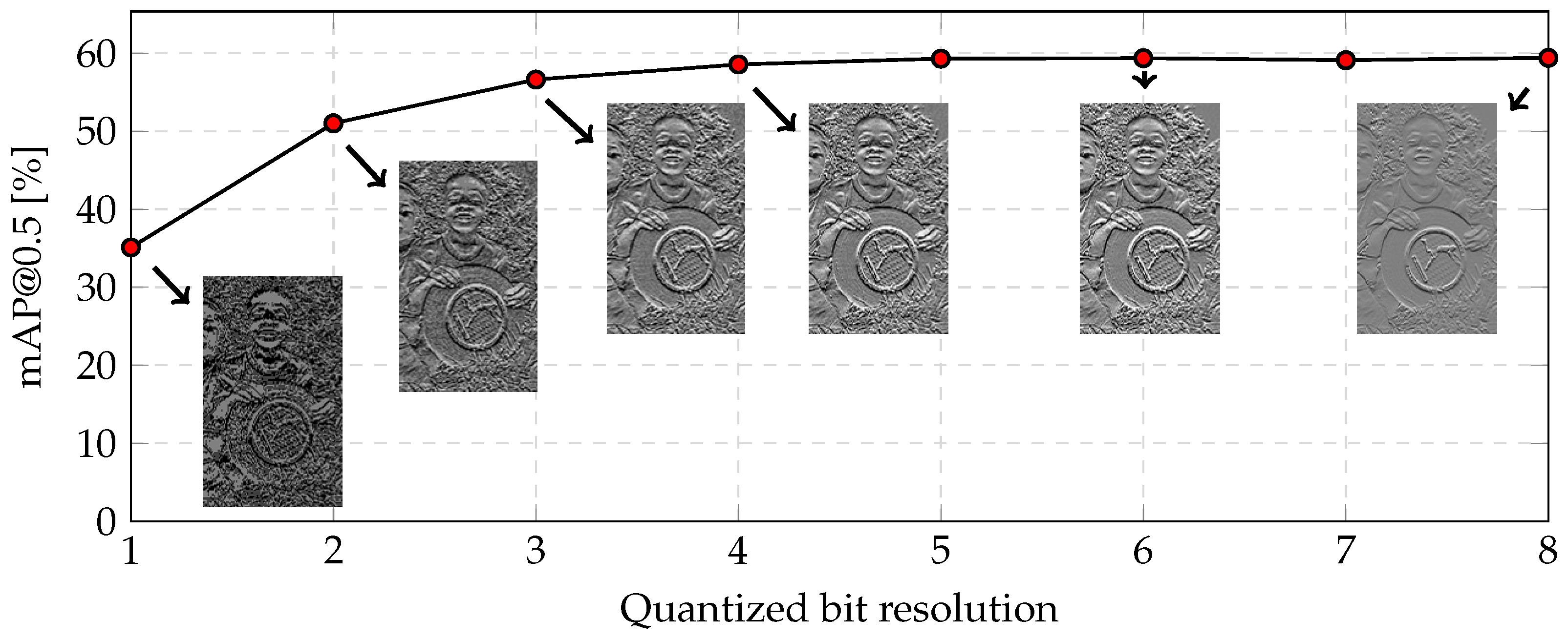
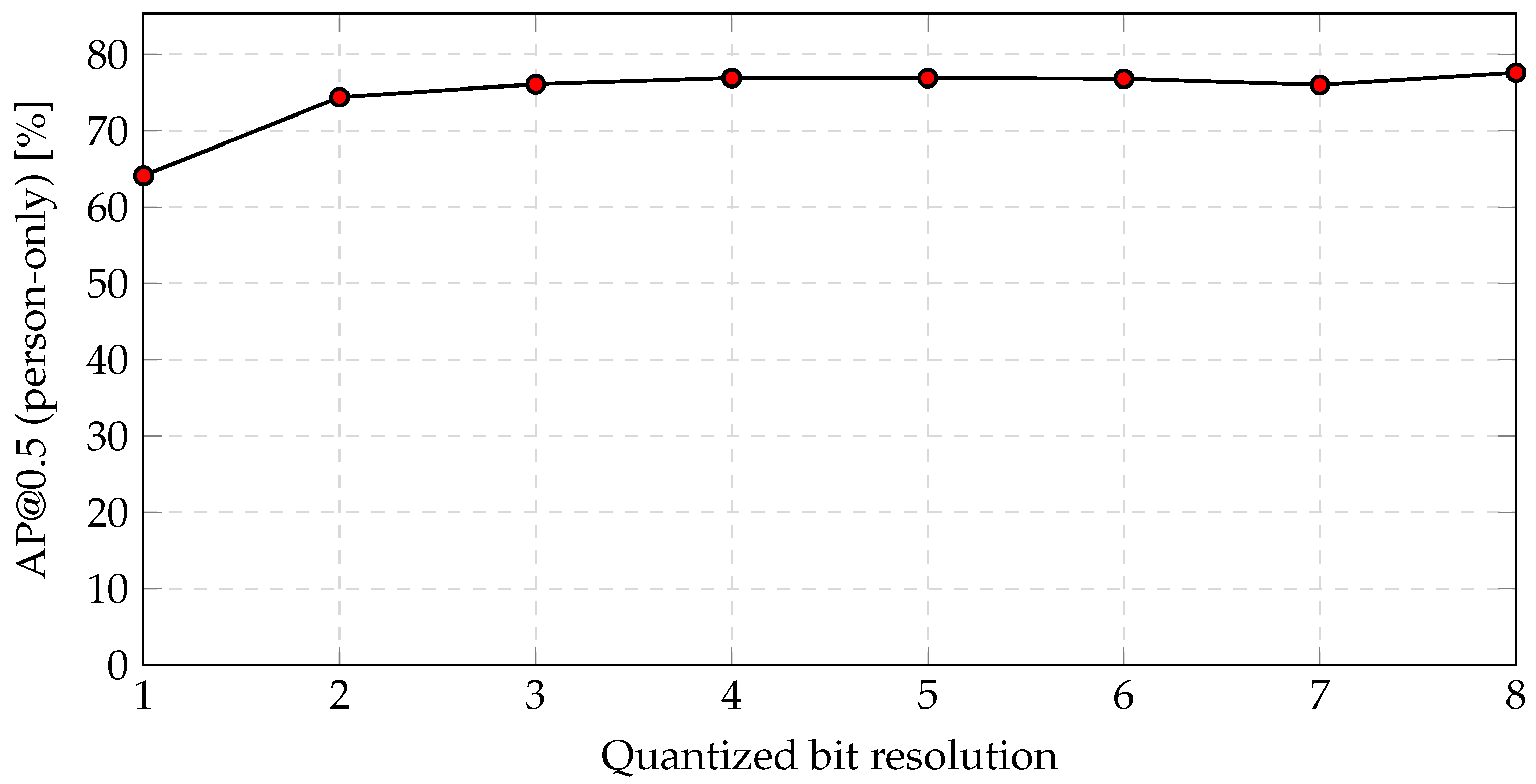
Figure 10 shows object recognition accuracy following quantization in which clipping is fixed at a two-bit resolution. As the quantized bit resolution decreases, the visibility of object edges deteriorates due to significant background noise. It was confirmed that the degradation of object recognition accuracy is minimal above a 3-bit resolution, but the degradation of object recognition accuracy is considerably large below a two-bit resolution. As a result, a resolution of three bits should be considered for feature data. As the quantized bit resolution decreases, the visibility of the edge of objects becomes poor due to considerable background noise, and the degradation of object recognition accuracy is considerably below a two-bit resolution. The object recognition accuracy was , which represents a reduction of relative to the 8-bit RGB color image. Meanwhile, the amount of data was reduced by (calculated as ).
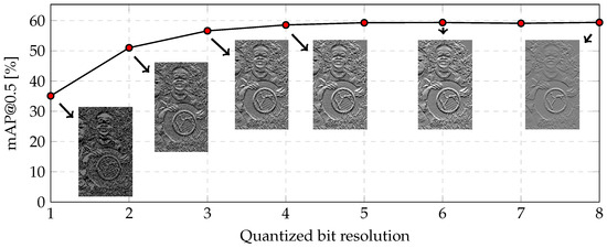
Figure 10.
Object recognition accuracy on the COCO dataset following quantization in which clipping is fixed at a two-bit resolution.
3.4. Discussion
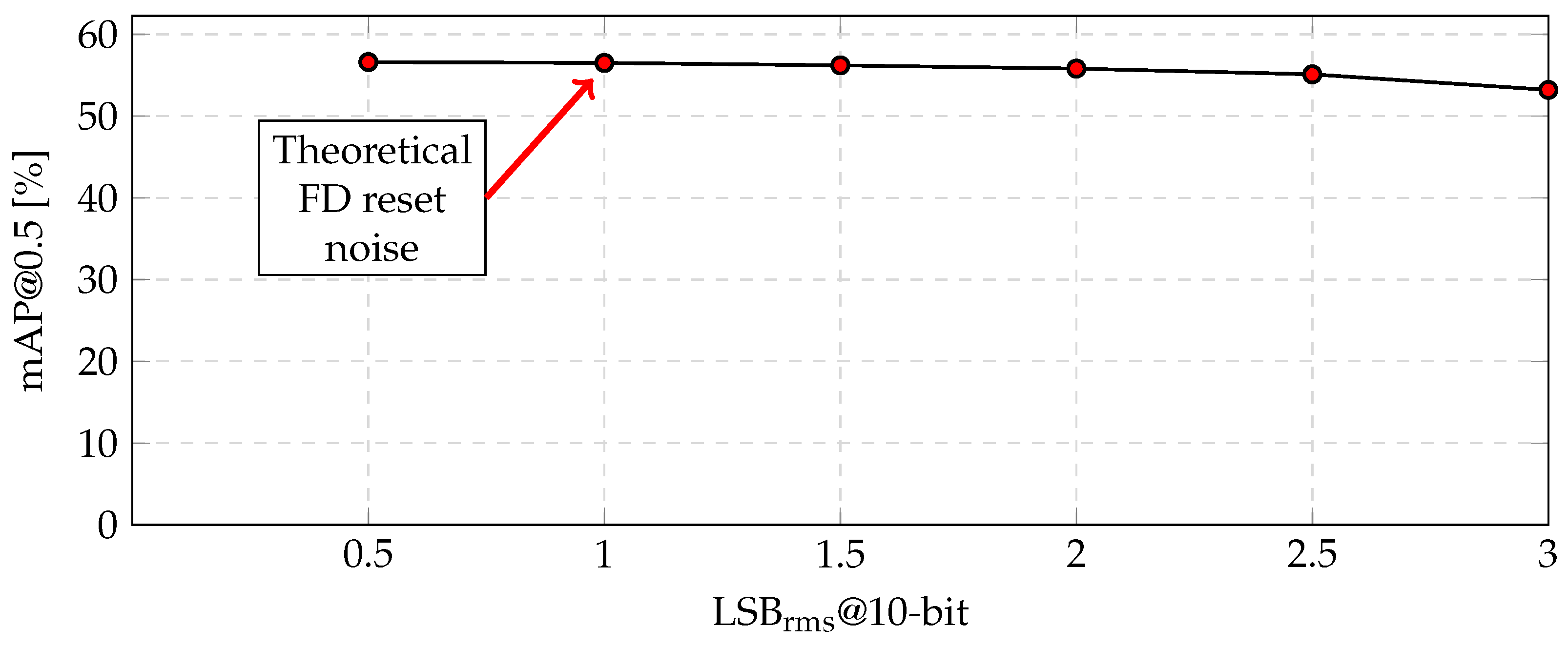
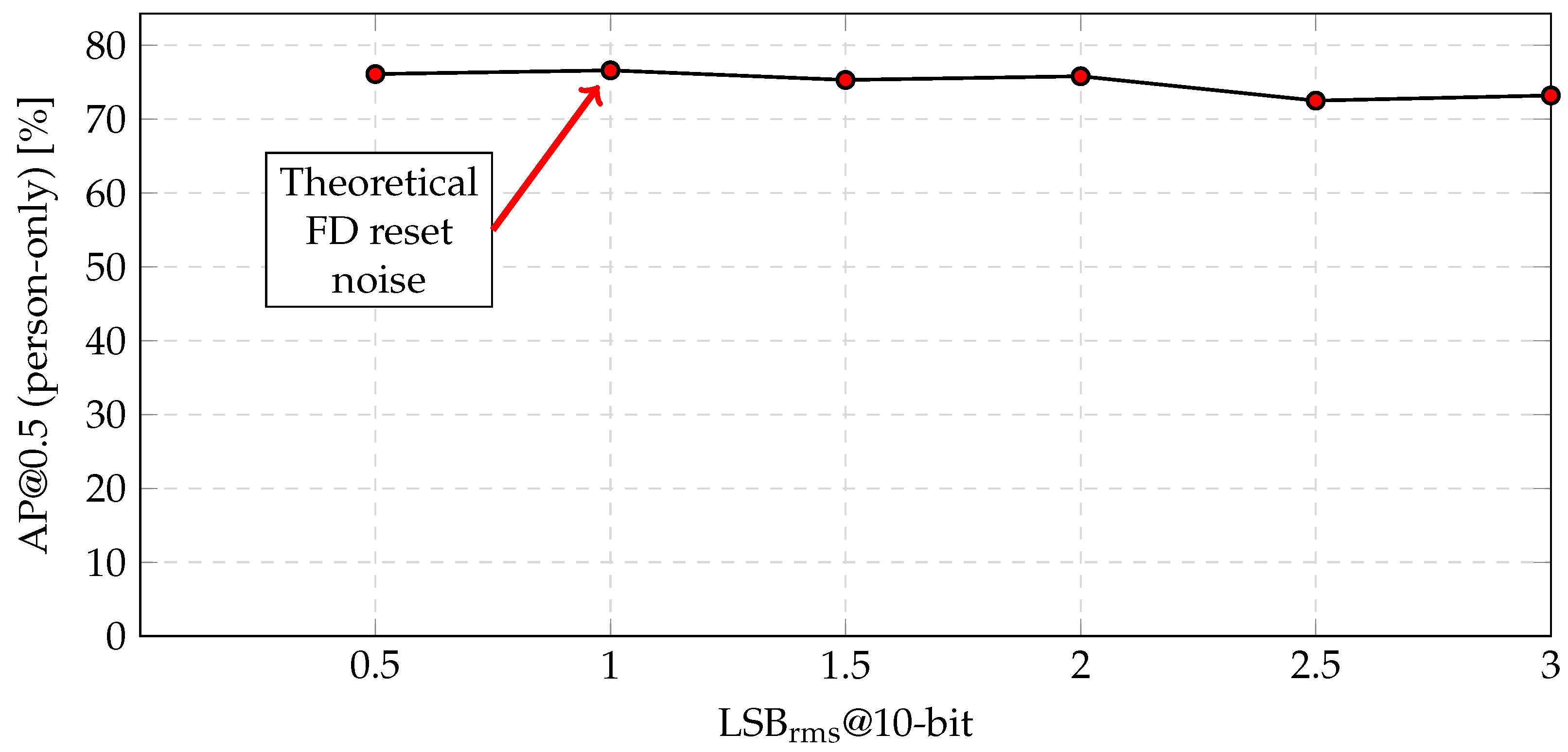
The aforementioned processing flow, which incorporates grayscale conversion, horizontal edge extraction, 3-bit quantization, and two-column binning, is a potential method of fabricating the proposed CMOS image sensor. The amount of the feature data was reduced by relative to the conventional RGB color image, even though the object recognition accuracy was reduced by only ( = ). For the fabrication, the robustness to additional noise was also verified, as shown in Figure 11. The theoretical FD reset noise was at a 10-bit resolution. However, even when the noise increased to , the accuracy decreased by only (=).
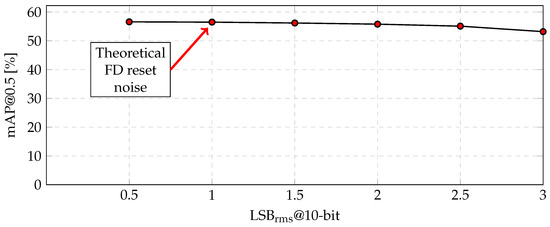
Figure 11.
Object recognition accuracy versus the amount of noise on the COCO dataset.
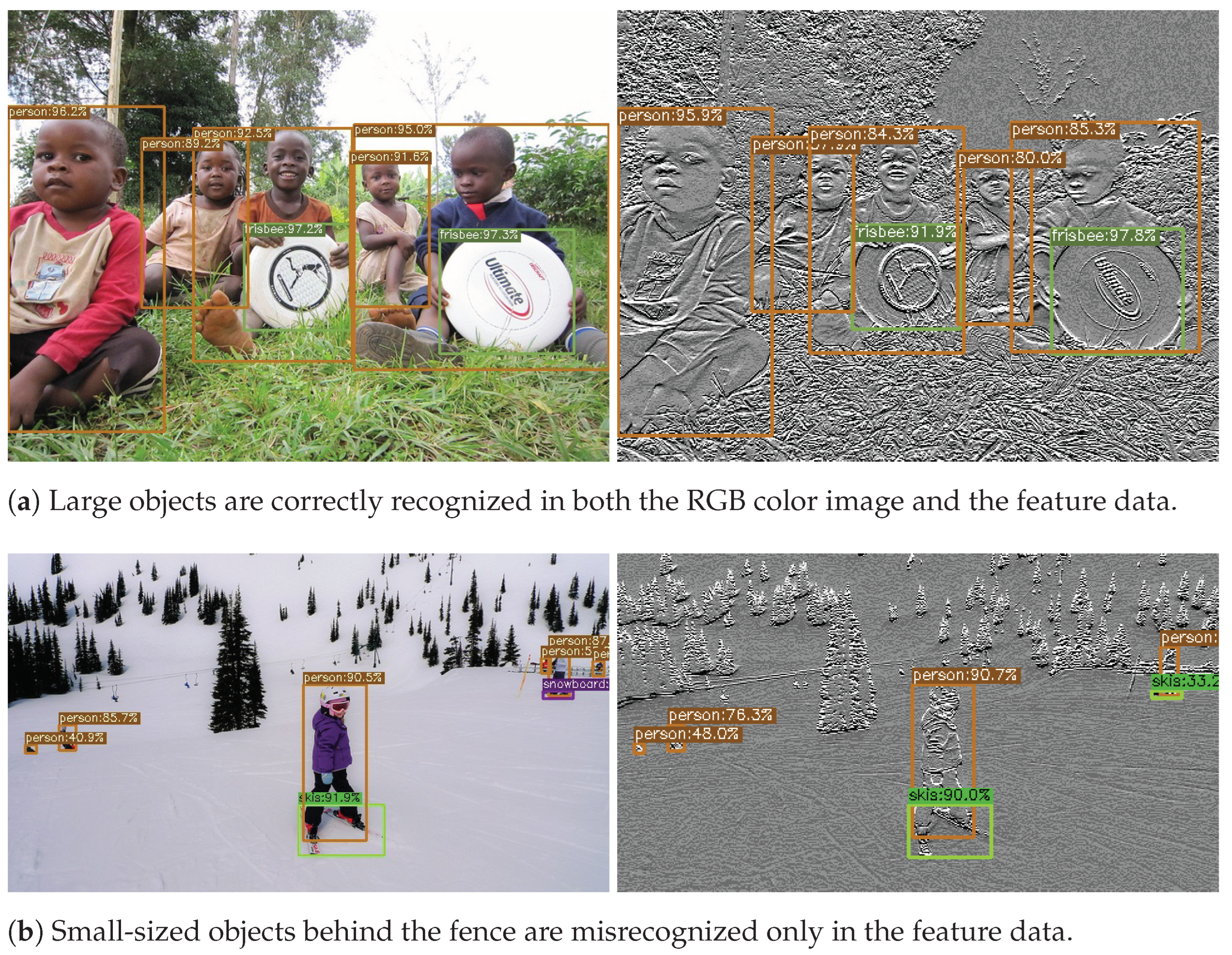
Here, let us take the image recognition system shown in Figure 1 as an example. Object recognition accuracy according to object size is summarized in Table 4, where , , and are the recognition accuracies for small, medium, and large objects, respectively. In relation to large objects, the feature data quantized to 3-bit resolution achieved , and the degradation of the mAP was 7.4% (=). Furthermore, when the trigger that causes the operation mode of the CMOS image sensor to shift from feature data mode to RGB color image mode is the detection of a large-sized person, the feature data quantized to 3-bit resolution achieved mAP and a degradation of only 3.4% (=). Because the YOLOX trained with feature data shows lower recognition accuracy for small objects with simple rectangular shapes, such as books, ties, and microwaves, the accuracy with which small objects are detected can be improved by switching the operation mode of the CMOS image sensor to RGB color mode. Sample images of recognition results according to object size are shown in Figure 12. In Figure 12a, all objects are correctly recognized in both the RGB color image and the feature data. In Figure 12b, the two small people behind the fence on the right side are misrecognized as false negatives only in the feature data.
Table 4.
Object recognition accuracy for each object scale.

Figure 12.
Sample images of recognition results according to object size on the COCO dataset [8].
4. Simulation Results for RAISE Dataset
As shown in Section 3, the proposed data reduction scheme for features was validated through object recognition using the large-scale COCO dataset. As shown in this section, in order to simulate the proposed on-chip processing of the image sensor more accurately, the dataset was replaced with the RAISE RAW image dataset. While the COCO dataset consists of demosaiced and lossy-compressed RGB channels, the RAISE dataset consists of uncompressed RAW images that are consistent with the output of image sensors. However, the RAISE dataset does not include labels and bounding boxes for objects. Therefore, 61 images were randomly selected from the RAISE dataset, and labels and bounding boxes were added to ‘person’ objects in these images to serve as test data for the YOLOX model trained with the COCO dataset. It is noted that object recognition on the RAISE dataset with a single class is a simpler task, and its accuracy can be higher than that on the COCO dataset with 80 classes.
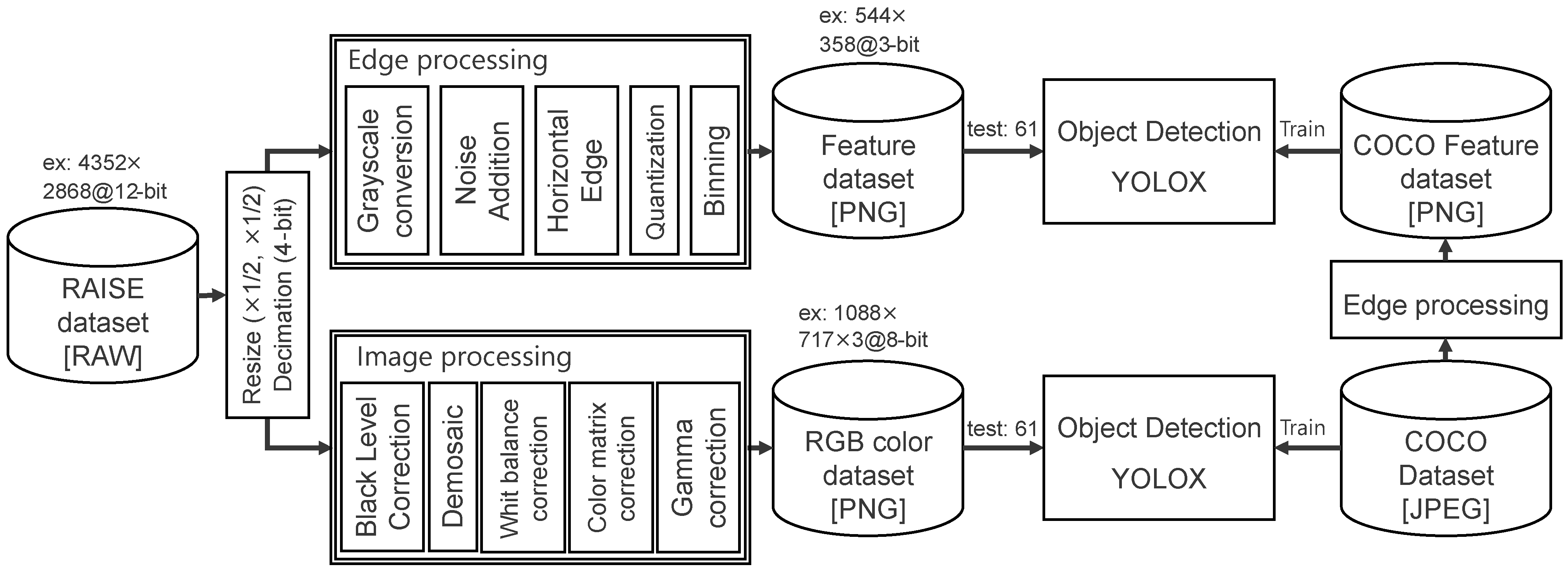
Figure 13 shows a simulation flow used to evaluate the RAISE feature dataset. Since the images in the RAISE dataset are mostly pixels in size, the image is first resized by halving both its horizontal and vertical dimensions, making it comparable to 2 Mpixel, which is the size required for the proposed CMOS image sensor. The 12-bit resolution of the RAW image is also reduced to an 8-bit resolution through 4-bit decimation. Grayscale conversion, FD reset noise addition, horizontal edge extraction, aggressive quantization, and binning are then performed to generate the RAW feature dataset in PNG format. Therefore, the amount of RAISE feature data is similar to the amount of raw COCO feature data. For reference, an RGB color dataset in PNG format is also generated from the RAISE RAW dataset using typical image processing. Such image processing includes black level correction, white balance correction, color matrix correction, and gamma correction. The dataset was tested using the YOLOX model trained with the COCO dataset.

Figure 13.
Processing flow used to generate the RAISE RGB color dataset and RAISE feature dataset.
4.1. Grayscale Conversion and Horizontal Edge Extraction
Object recognition accuracy values are summarized in Table 5, where the RAW dataset with grayscale conversion, horizontal edge extraction, and binning remains at 8-bit resolution. The RAISE feature data achieved an accuracy of , while the RAISE RGB color image achieved an accuracy of . This trend is consistent with tests performed on the COCO dataset, in which the accuracy achieved with feature data is approximately lower than that achieved with the RGB color image. Recall that object recognition on the RAISE dataset with a single class achieves higher accuracy than that on the COCO dataset with 80 classes (see Table 2).
Table 5.
Object recognition accuracy for the RAISE dataset.
Examples of a RAISE RGB color image and RAISE feature data are shown in Figure 14, where the RGB color image and feature data are resized to an identical aspect ratio for the sake of visibility. Figure 14a,b show an 8-bit RGB color image and the distribution of the corresponding histogram, respectively. Even though the two people on the right of the image in Figure 14c are probably not visible to human eyes, YOLOX can recognize them correctly. The histogram of the RAW feature data shown in Figure 14d is narrow and central, behaving in a similar manner to the COCO feature data.

Figure 14.
Sample images from the RAISE dataset [25] and their respective histograms.
4.2. Horizontal Binning
The effect of horizontal binning on object recognition accuracy is summarized in Table 6, where the RAISE feature data remain in 8-bit resolution. The trend is also consistent with the test performed on the COCO dataset (see Table 3), in which the 2-Bin configuration shows the highest accuracy. Therefore, aggressive quantization was similarly applied only to the 2-Bin RAISE feature data.
Table 6.
Effect of horizontal binning on object recognition accuracy on the RAISE dataset.
4.3. Quantization
The effect of quantization on object recognition accuracy is summarized in Figure 15, where the RAISE feature data are quantized to three-, four-, or five-bit resolution using decimation, clipping, or a combination of both. The trend in this effect is similar, except that the recognition accuracy is highest after 3-bit clipping. Since edge processing does not include forms of tone-mapping such as gamma correction, the contrast in the RAISE feature data is slightly less pronounced than that in the COCO feature data. Therefore, the contrast was enhanced with a higher number of clipping bits as compared to the COCO feature dataset (see Figure 9).
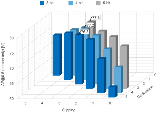
Figure 15.
Object recognition accuracy on the RAISE dataset for three-, four-, and five-bit resolution.
Figure 16 shows the accuracy of object recognition following quantization in which clipping is fixed at a 3-bit resolution.
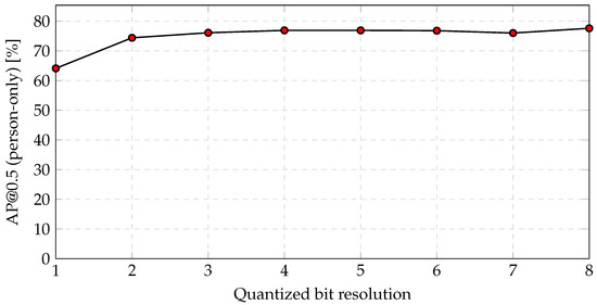
Figure 16.
Object recognition accuracy on the RAISE dataset following quantization in which clipping is fixed at a 3-bit resolution.
The trend is consistent with the test on the COCO dataset (see Figure 10), in which accuracy underwent considerably greater degradation below a two-bit resolution. As a result, a 3-bit resolution is appropriate for feature data. The object recognition accuracy is , representing a fall of compared to the 8-bit RAISE RGB color images.
4.4. Discussion
The amount of RAISE feature data was reduced by compared to the conventional RGB color images, even though the accuracy of object recognition was reduced by only 10.7% (=). The robustness to additional noise was also verified, as shown in Figure 17. This trend is consistent with the test on the COCO dataset (see Figure 11), where even if the noise increases to at a 10-bit resolution, the accuracy decreases by only 0.5% (=).
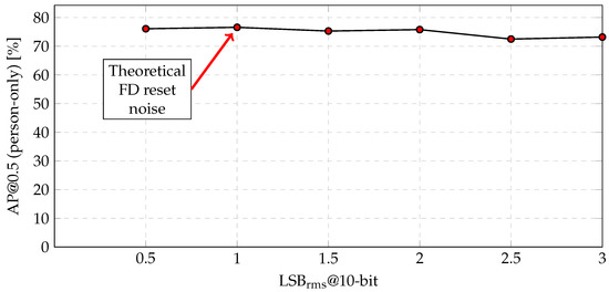
Figure 17.
Object recognition accuracy versus the amount of noise on the RAISE dataset.
Sample images of our recognition results are shown in Figure 18. Their trend is consistent with the test on the COCO dataset (see Figure 12b), where the two small-sized people in the shadows are misrecognized as false negatives only in the feature data.
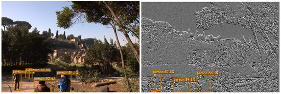
Figure 18.
Examples of object recognition results on the RAISE dataset [25].
Since the RAISE dataset showed similar results to the COCO dataset, the feature data output from the CMOS image sensor are expected to achieve similar accuracy to the simulation results for the COCO dataset when on-chip data reduction is implemented in the CMOS image sensor.
5. Conclusions and Future Work
In this paper, we proposed a data reduction scheme for features extracted by a CMOS image sensor and presented results produced in simulations of object recognition using feature data. The feature data are extracted via a processing pipeline that incorporates RGB-to-grayscale conversion, edge extraction, aggressive quantization, and signal binning, which takes place in a CMOS image sensor. According to the simulation results, we achieved object recognition accuracy in the COCO dataset and object recognition accuracy in the RAISE dataset, even though the amount of data was reduced by relative to conventional RGB color images. While this level of accuracy may not be sufficient for some applications, the feature data achieved mAP for a specific object, such as large-sized persons. This specific object can be used as a trigger to switch the operation mode of the CMOS image sensor from feature data mode to RGB color image mode.
An image sensor will be fabricated in order to demonstrate this energy-efficient image recognition system which utilizes feature data and RGB color images. In addition to the data reduction techniques presented in this paper, a lightweight DNN model and a low-power ADC for the feature data are necessary to realize low-power image recognition systems.
Author Contributions
Conceptualization, S.O.; methodology, Y.M. and K.Y.; software, Y.M. and K.Y.; validation, Y.M.; writing—original draft preparation, Y.M.; writing—review and editing, K.Y. and S.O.; supervision, R.U., D.M. and S.O.; project administration, H.S. and S.O. All authors have read and agreed to the published version of the manuscript.
Funding
This work was supported by JSPS KAKENHI, grant number JP20K04630.
Data Availability Statement
The feature data used to evaluate the accuracy in this study are openly available at “https://github.com/ri0107pr/Feature-dataset/tree/main”, accessed on 27 August 2024.
Conflicts of Interest
Authors Ryuichi Ujiie, Daisuke Morikawa, Hideki Shima are employed by Technology Development Division, Nisshinbo Micro Devices Inc. The remaining authors declare that the research was conducted without anycommercial or financial relationships that could be viewed as apotential conflict of interest.
Abbreviations
The following abbreviations are used in this manuscript:
| CMOS | Complementary Metal–Oxide Semiconductor; |
| IoT | Internet of Things; |
| QVGA | Quarter Video Graphics Array; |
| RGB | Red, Green, and Blue; |
| AI | Artificial Intelligence; |
| DNN | Deep Neural Network; |
| HOG | Histogram of Oriented Gradient; |
| MAC | Multiply–Accumulate; |
| EVS | Event-based Vision Sensor; |
| ADC | Analog-to-Digital Converter; |
| MIPI | Mobile Industry Processor Interface; |
| SAR | Successive Approximation Register; |
| DAC | Digital-to-Analog Converter; |
| LSB | Least Significant Bit; |
| rms | root mean square; |
| mAP | mean Average Precision; |
| IoU | Intersection over Union. |
References
- Cabinet Office, Government of Japan. Society 5.0. Available online: https://www8.cao.go.jp/cstp/english/society5_0/index.html (accessed on 5 November 2023).
- Simonyan, K.; Zisserman, A. Very Deep Convolutional Networks for Large-Scale Image Recognition. arXiv 2015, arXiv:1409.1556. [Google Scholar]
- He, K.; Zhang, X.; Ren, S.; Sun, J. Deep Residual Learning for Image Recognition. In Proceedings of the IEEE Conference on Computer Vision and Pattern Recognition (CVPR), Las Vegas, NV, USA, 27–30 June 2016. [Google Scholar]
- Girshick, R. Fast R-CNN. In Proceedings of the IEEE International Conference on Computer Vision (ICCV), Santiago, Chile, 7–13 December 2015. [Google Scholar]
- Redmon, J.; Divvala, S.; Girshick, R.; Farhadi, A. You Only Look Once: Unified, Real-Time Object Detection. In Proceedings of the IEEE Conference on Computer Vision and Pattern Recognition (CVPR), Las Vegas, NV, USA, 27–30 June 2016. [Google Scholar]
- Howard, A.G.; Zhu, M.; Chen, B.; Kalenichenko, D.; Wang, W.; Weyand, T.; Andreetto, M.; Adam, H. Mobilenets: Efficient convolutional neural networks for mobile vision applications. arXiv 2017, arXiv:1704.04861. [Google Scholar]
- Courbariaux, M.; Hubara, I.; Soudry, D.; El-Yaniv, R.; Bengio, Y. Binarized neural networks: Training deep neural networks with weights and activations constrained to +1 or −1. arXiv 2016, arXiv:1602.02830. [Google Scholar]
- Lin, T.Y.; Maire, M.; Belongie, S.; Hays, J.; Perona, P.; Ramanan, D.; Dollár, P.; Zitnick, C.L. Microsoft COCO: Common Objects in Context. In Proceedings of the Computer Vision—ECCV 2014; Fleet, D., Pajdla, T., Schiele, B., Tuytelaars, T., Eds.; Springer: Cham, Switzerland, 2014; pp. 740–755. [Google Scholar]
- Everingham, M.; Van Gool, L.; Williams, C.; Winn, J.; Zisserman, A. The Pascal Visual Object Classes Challenge 2012 (voc2012). In Proceedings of the Results. 2012. Available online: http://www.pascal-network.org/challenges/VOC/voc2012/workshop/index.html (accessed on 2 July 2024).
- Russakovsky, O.; Deng, J.; Su, H.; Krause, J.; Satheesh, S.; Ma, S.; Huang, Z.; Karpathy, A.; Khosla, A.; Bernstein, M.; et al. Imagenet large scale visual recognition challenge. Int. J. Comput. Vis. 2015, 115, 211–252. [Google Scholar] [CrossRef]
- Suzuki, J.; Yu, J.; Yasunaga, M.; García-Arias, Á.L.; Okoshi, Y.; Kumazawa, S.; Ando, K.; Kawamura, K.; Van Chu, T.; Motomura, M. Pianissimo: A Sub-mW Class DNN Accelerator with Progressively Adjustable Bit-Precision. IEEE Access 2024, 12, 2057–2073. [Google Scholar] [CrossRef]
- Yoo, J.; Lee, D.; Son, C.; Jung, S.; Yoo, B.; Choi, C.; Han, J.J.; Han, B. RaScaNet: Learning Tiny Models by Raster-Scanning Images. In Proceedings of the IEEE/CVF Conference on Computer Vision and Pattern Recognition (CVPR), Nashville, TN, USA, 20–25 June 2021; pp. 13673–13682. [Google Scholar]
- Yehui, T.; Kai, H.; Jianyuan, G.; Chang, X.; Chao, X.; Yunhe, W. GhostNetV2: Enhance Cheap Operation with Long-Range Attention. arXiv 2022, arXiv:2211.12905. [Google Scholar]
- Young, C.; Omid-Zohoor, A.; Lajevardi, P.; Murmann, B. A Data-Compressive 1.5/2.75-bit Log-Gradient QVGA Image Sensor With Multi-Scale Readout for Always-On Object Detection. IEEE J. Solid-State Circuits 2019, 54, 2932–2946. [Google Scholar] [CrossRef]
- Yoneda, S.; Negoro, Y.; Kobayashi, H.; Nei, K.; Takeuchi, T.; Oota, M.; Kawata, T.; Ikeda, T.; Yamazaki, S. Image Sensor Capable of Analog Convolution for Real-time Image Recognition System Using Crystalline Oxide Semiconductor FET. Int. Image Sensors Soc. 2019, 322–325. [Google Scholar]
- Choi, J.; Park, S.; Cho, J.; Yoon, E. A 3.4-μ W Object-Adaptive CMOS Image Sensor With Embedded Feature Extraction Algorithm for Motion-Triggered Object-of-Interest Imaging. IEEE J. Solid-State Circuits 2014, 49, 289–300. [Google Scholar] [CrossRef]
- Hsu, T.H.; Chen, Y.R.; Liu, R.S.; Lo, C.C.; Tang, K.T.; Chang, M.F.; Hsieh, C.C. A 0.5-V Real-Time Computational CMOS Image Sensor With Programmable Kernel for Feature Extraction. IEEE J. Solid-State Circuits 2021, 56, 1588–1596. [Google Scholar] [CrossRef]
- Finateu, T.; Niwa, A.; Matolin, D.; Tsuchimoto, K.; Mascheroni, A.; Reynaud, E.; Mostafalu, P.; Brady, F.; Chotard, L.; LeGoff, F.; et al. 5.10 A 1280 × 720 Back-Illuminated Stacked Temporal Contrast Event-Based Vision Sensor with 4.86 μm Pixels, 1.066 GEPS Readout, Programmable Event-Rate Controller and Compressive Data-Formatting Pipeline. In Proceedings of the 2020 IEEE International Solid- State Circuits Conference—(ISSCC), San Francisco, CA, USA, 16–20 February 2020; pp. 112–114. [Google Scholar] [CrossRef]
- Lichtsteiner, P.; Posch, C.; Delbruck, T. A 128 × 128 120 db 30 mw asynchronous vision sensor that responds to relative intensity change. In Proceedings of the 2006 IEEE International Solid-State Circuits Conference-Digest of Technical Papers, Francisco, CA, USA, 6–9 February 2006; pp. 2060–2069. [Google Scholar]
- Son, B.; Suh, Y.; Kim, S.; Jung, H.; Kim, J.S.; Shin, C.; Park, K.; Lee, K.; Park, J.; Woo, J.; et al. 4.1 A 640 × 480 dynamic vision sensor with a 9 μm pixel and 300 Meps address-event representation. In Proceedings of the 2017 IEEE International Solid-State Circuits Conference (ISSCC), Francisco, CA, USA, 5–9 February 2017; pp. 66–67. [Google Scholar]
- Okura, S.; Otani, A.; Itsuki, K.; Kitazawa, Y.; Yamamoto, K.; Osuka, Y.; Morikaku, Y.; Yoshida, K. A Study on a Feature Extractable CMOS Image Sensor for Low-Power Image Classification System. In Proceedings of the International Image Sensor Workshop, Scotland, UK, 21–25 May 2023; p. 33. [Google Scholar]
- Ge, Z.; Liu, S.; Wang, F.; Li, Z.; Sun, J. YOLOX: Exceeding YOLO Series in 2021. arXiv, 2021; arXiv:2107.08430. [Google Scholar]
- Morikaku, Y.; Ujiie, R.; Morikawa, D.; Shima, H.; Yoshida, K.; Okura, S. On-chip data reduction and object detection for a feature extractable CMOS image sensor. In Proceedings of the International Workshop on Advanced Imaging Technology (IWAIT) 2024; Nakajima, M., Lau, P.Y., Kim, J.G., Kubo, H., Chang, C.Y., Kemao, Q., Eds.; International Society for Optics and Photonics, SPIE: Bellingham, WA, USA, 2024; Volume 13164, p. 1316413. [Google Scholar] [CrossRef]
- Kanan, C.; Cottrell, G.W. Color-to-Grayscale: Does the Method Matter in Image Recognition? PLoS ONE 2012, 7, e29740. [Google Scholar] [CrossRef] [PubMed]
- Dang-Nguyen, D.T.; Pasquini, C.; Conotter, V.; Boato, G. RAISE: A raw images dataset for digital image forensics. In Proceedings of the 6th ACM Multimedia Systems Conference, New York, NY, USA, 18–20 March 2015; MMSys ’15. pp. 219–224. [Google Scholar] [CrossRef]


Disclaimer/Publisher’s Note: The statements, opinions and data contained in all publications are solely those of the individual author(s) and contributor(s) and not of MDPI and/or the editor(s). MDPI and/or the editor(s) disclaim responsibility for any injury to people or property resulting from any ideas, methods, instructions or products referred to in the content. |
© 2024 by the authors. Licensee MDPI, Basel, Switzerland. This article is an open access article distributed under the terms and conditions of the Creative Commons Attribution (CC BY) license (https://creativecommons.org/licenses/by/4.0/).