Abstract
Continuous-flow microfluidic biochips are a type of biochip technology based on microfluidic channels that enable various biological experiments and analyses to be performed on a tiny chip. They have the advantages of a high throughput, high sensitivity, high precision, low cost, and quick response. In the architectural synthesis of continuous-flow microfluidic biochips (CFMBs), prior work has not considered reducing component interconnection requirements, which led to an increase in the number of connection pairs. In this paper, we propose an architectural synthesis flow for continuous-flow microfluidic biochips with connection pair optimization, which includes high-level synthesis, placement, and routing. In the high-level synthesis stage, our method reduces the need for component interconnections, which reduces the number of connection pairs. Our method performs fine-grained binding, ultimately obtaining high-quality binding and scheduling results for flow paths. Based on the high-quality binding results, we propose a port placement strategy based on port correlation and subsequently use a quadratic placer to place the components. During the routing stage, we employ a conflict-aware routing algorithm to generate flow channels to reduce conflicts between liquid transportation tasks. Experimental results on multiple benchmarks demonstrate the effectiveness of our method. Compared with the existing work, the proposed algorithm obtains average reductions of 35.34% in connection pairs, 24.30% in flow channel intersections, 21.71% in total flow channel length, and 18.39% in the execution time of bioassays.
1. Introduction
In recent years, continuous-flow microfluidic biochips (CFMBs) have garnered significant attention due to their remarkable capabilities. These microfabrication-based small chips have the power to manipulate minute liquid volumes with unparalleled precision. These chips play a pivotal role in enhancing the reliability and precision of a system by minimizing the interconnection and control demands among components. They are known as microfluidic chips, consisting primarily of microchannels and microvalves. The inclusion of these features empowers these chips to facilitate advanced biological analysis and detection with remarkable efficiency, sensitivity, and automation [1], and external devices have been used to support CFMBs [2].
The advent of big data technology has sparked significant growth in various regions, where the concept of smart cities is being promoted and the development of intelligent detection technology in Internet of Things (IoT) applications is being encouraged. Refs. [3,4,5] use Internet of Things technology to achieve intelligent agriculture to achieve real-time monitoring. CFMBs may also be applied in the future in the fields of medicine, biology, environmental monitoring, food safety, and timely elimination of possible hidden dangers. CFMBs have found extensive applications in diverse areas, including enzyme-linked immunosorbent assays [6], large-scale DNA analysis [7,8], clinical diagnostics [9,10], drug discovery [11], C-reactive protein (CRP) [12], cell detection [13], and so on.
CFMBs are commonly fabricated utilizing polydimethylsiloxane (PDMS) [14], an organosilicon polymer compound renowned for its exceptional biocompatibility, flexibility, and transparency. These properties of PDMS facilitate the seamless creation of microstructures and channels, crucial for the development of CFMBs. Moreover, the outstanding chemical characteristics of PDMS contribute to the precise and accurate execution of biochemical reaction experiments performed using CFMBs. In terms of their structure, CFMBs consist of various essential components, including channels, components, ports, and valves. Channels within CFMBs serve the purpose of transporting fluids. Components play specific roles such as heating, mixing, filtering, and detection. CFMBs feature two types of ports: input and output. Input ports enable the introduction of fluids or the application of pressure to drive fluid flow, whereas output ports facilitate waste drainage or the release of pressure from the channels. The valve is the key element of CFMBs, and it operates based on the deformation of an elastic membrane when subjected to pressure from a pressure source. When pressure is applied, the elastic membrane is deformed, effectively closing the valve and obstructing fluid flow through the channel. Conversely, when the pressure from the pressure source is released, the elastic membrane returns to its original shape, causing the valve to open and allowing fluid to flow through the channel [15].
With the rapid expansion of biochemical reactions, the design complexity of biochips has grown proportionately. In fact, biochips have already incorporated an extensive number of valves, exceeding 25,000, along with approximately one million features, to facilitate a remarkable 9216 parallel polymerase chain reactions [16]. Such intricate designs have made manual design practically unfeasible. Consequently, computer-aided design has become indispensable in obtaining the physical architecture of these chips. The automated design process for CFMBs can be divided into two fundamental steps: high-level synthesis and physics design.
CFMBs are designed based on a given bioassay. The protocol of an assay is called a sequencing graph. In the high-level synthesis stage, we bind and schedule operations based on the sequencing graph. Binding an operation requires determining which component executes an operation, and then determining the connection relationship between the component’s interfaces and ports. The scheduling of an operation requires determining the time interval for the operation to be executed and determining the time interval for its liquid input task, we also call this the liquid transportation task. In the placement stage, we determine the specific positions of the ports and components in the chip based on the binding and scheduling results of the high-level synthesis. In the routing stage, we obtain the channels that connect components to other components or ports based on the binding and placement results [17].
The interconnection requirements of components in CFMBs are determined by the interconnections between component interfaces, as well as between component interfaces and ports (where ports are considered as special components). Each component possesses two interfaces for liquid input and output. Connections between component interfaces, or between component interfaces and input/output ports, are referred to as connection pairs.
In addressing the binding and scheduling problem during high-level synthesis, Minhass et al. [18] introduced the use of sequencing graphs to model bioassays. They employed list scheduling as a method to search for the optimal solution. On the other hand, ref. [19] pioneered an approach that prioritizes storage minimization as the objective during high-level synthesis. Their aim was to enhance chip efficiency and decrease the execution time of bioassays; they formulated the binding and scheduling tasks using mathematical formulas. To find the optimal solution, they utilized an integer linear programming (ILP) solver.
In addressing the placement and routing problem, ref. [20] introduced a simulated annealing placement algorithm based on sequence pairs. They incorporated a negotiation strategy within the algorithm to handle connection routing, while also employing a bounding-box strategy to adjust component positions effectively. Ref. [21], building upon ref. [20], proposes a placement algorithm based on Discrete Particle Swarm Optimization (DPSO) and a collaborative design algorithm for placement and routing, resulting in an improved chip architecture. Ref. [22] transformed the binding and scheduling problem into a weighted finite resource problem. They constructed resource and dependency constraint formulas and utilized a solver to search for the optimal solution. Ref. In a different approach, ref. [23] transformed the binding and scheduling problem into the classic maximum independent set problem in graph theory. They employed a solver to handle routing tasks and utilized a collaborative design algorithm to optimize the flow layer and control layer within the biochip design. For distributed storage architectures, ref. [24] proposed a delay-aware binding and scheduling algorithm. They used a simulated annealing algorithm for placement, an A* algorithm for routing, and implemented cleaning optimization techniques to enhance the overall design. Ref. [25] presented a comprehensive approach called MiniControl, which tackles the high-level synthesis problem under stringent constraints of control ports. They employed a Particle Swarm Optimization (PSO) algorithm for high-level synthesis, followed by a simulated annealing algorithm for placement and an A* algorithm for routing. By leveraging these techniques, they were able to achieve a relatively optimal solution. Ref. [26] employed an ILP algorithm for both high-level synthesis and physical design. Notably, they integrated liquid-handling operations into the high-level synthesis and physical design process for the first time. Additionally, they successfully achieved volume management, addressing an important aspect of biochip design.
However, the aforementioned studies overlooked the importance of reducing the interconnection requirements of components during the high-level synthesis stage, as well as neglecting port binding considerations. Furthermore, in the placement stage, the relative positions of ports and component interfaces were disregarded, which could have repercussions on subsequent routing and rescheduling processes. This oversight may lead to an increased channel length, a higher number of flow-channel crossings, and extended execution time of bioassays. Ultimately, these factors can lead to escalated costs of biochips and diminished chip efficiency. The costs of CFMBs are evaluated by the number of intersections and the total length of the channel; the efficiency of a CFMB is evaluated by the execution time of the biochemical reaction.
In response to the limitations observed in previous work, we propose an architecture synthesis method that centers around connection pair optimization. Our proposed method aims to not only reduce the cost of CFMBs but also enhance their efficiency, offering a fresh perspective for CFMB design. The main contributions of this paper can be summarized as follows:
- (1)
- We propose a high-level synthesis algorithm that considers the requirements of component interconnections for high-quality binding and scheduling. Reasonable reuse of existing flow paths includes the reuse of logical channels formed between ports and component interfaces (that is, the connection relationship between ports and component interfaces), and includes the reuse of logical channels between component interfaces. The number of connection pairs is reduced, thereby optimizing the wire network and finally generating the binding of the liquid transport task to the connection relationship. The binding of operations and liquid transportation tasks is based on the scheduling of operations, and the influence of the multiplexed channels on the total biochemical reaction time is considered with the reuse of logical channels. Then, the number of connection pairs formed by components and ports and components is reduced without increasing the total biochemical reaction time.
- (2)
- We propose a physical design method for improving the efficiency and reducing the costs of CFMBs. Our approach takes into account the high-quality binding results from high-level synthesis and the characteristics of flow paths during placement. We introduce the concept of port relevance and prioritize the placement of ports. We then employ a quadratic placer to place the components. During routing, we employ a conflict-aware routing algorithm to generate flow channels based on the flow paths, which reduces conflicts between liquid transportation tasks. Using this method, we can effectively reduce chip costs and improve the execution efficiency of CFMBs.
- (3)
- Experimental results on multiple benchmarks confirm that the proposed synthesis flow leads to a lower number of connection pairs, a lower number of intersections, a lower total channel length, and less total execution time. Compared with existing work, our method can significantly reduce the connection pairs by 35.34%, the intersections by 24.30%, the total length of flow channels by 21.71%, and the total execution time by 18.39%.
The rest of this paper is organized as follows: Section 2 introduces the problem model and design challenges. Section 3 presents the details and implementation steps of the proposed algorithm. Section 4 describes and discusses the experiments conducted in this paper. Finally, Section 5 provides a summary of the entire paper.
2. Background and Problem Formulation
During the high-level synthesis stage of CFMBs, biochemical reactions are typically modeled as a sequencing graph , as shown in Figure 1, where represents an operation of a biochemical reaction and includes information such as the operation type and execution time, while specifies the dependency between operations and operation is a parent node of in G. In high-level synthesis, two objectives are accomplished based on the sequencing graph:
Figure 1.
Sequencing graph.
- (1)
- The formation of a binding scheme , where represents the j-th fluid input task of operation , and represents the j-th complete fluid transportation path consisting of multiple connection pairs. For example, if it is necessary to transport the liquid of component to component, three connection pairs are required: , where is the pressure input port, is interface A of component , is interface B of component , is interface A of component , is interface B of component , and is the pressure output port. The liquid is emitted from interface B of component and subsequently transported to component through interface A of component .
- (2)
- The scheduling scheme, which determines the time for each operation and its liquid input tasks. In the placement of CFMBs, the specific positions of ports and component interfaces are determined based on the connection pairs obtained from high-level synthesis, taking into account their relative positions and their impact on subsequent routing and rescheduling stages. In the routing stage, fluid transport channels that minimize conflicts are generated.
2.1. Motivation
In the flow-layer design of CFMBs, it is crucial to optimize key metrics such as the total length of flow channels, the number of intersections, and the overall execution time of biochemical reactions. However, existing methods have overlooked potential improvements that can be achieved by reducing the demand for component interconnections. Since it is impossible to know the specific length of the channel in the high-level synthesis stage and it is impossible to judge the possible conflicts between various liquid transport tasks, if the overall execution time of biochemical reactions needs to be obtained, rescheduling should be carried out after the generation of the CFMB’s architecture to obtain the final scheduling result. To optimize the key indicators mentioned above, we incorporate the objectives of routing and rescheduling early on, during both the high-level synthesis and placement stages. Additionally, we employ a strategy to enhance optimization by reducing the granularity of flow paths. This is achieved by dividing the paths into multiple connection pairs, where each pair consists of either a port and a component interface or two component interfaces. This approach allows for more fine-grained control and optimization of the flow paths in order to improve overall performance.
Considering the sequencing graph depicted in Figure 1, we employ two mixers, two detectors, four input ports, and four output ports. Using the list scheduling algorithm [18] during the high-level synthesis stage, we bind each operation by selecting the earliest available component and port. This process generates binding scheme 1, which is presented in both Table 1 and Table 2.
Table 1.
Binding scheme 1: binding results of components of operations.
Table 2.
Binding scheme 1: transportation tasks with the flow path.
In Table 2, represents a transport task that transports the output fluid of operation to the component where operation is bound. Furthermore, detector represents interface A of detector. This binding scheme generates a total of 10 different transportation paths (as shown in Table 2) and 14 different connection pairs, such as and so on.
Given a binding scheme, we can generate two different CFMB architectures: (1) a placement with a minimized channel length; (2) a placement with minimized transportation conflicts.
Figure 2a illustrates the placement with a minimized channel length for binding scheme 1, which has eight intersections. As shown in Figure 3, conflicts arise during the rescheduling process between the inputs of ( and (). Additionally, conflicts arise between the inputs of and (). These two conflicts collectively result in a delay of 8 s. Consequently, the total execution time of the biochemical reactions amounts to 48 s.
Figure 2.
Two biochip placements for binding scheme 1. (a) A placement with a minimized channel length. (b) A placement with minimized transportation conflicts.
Figure 3.
Binding scheme 1: rescheduling for the placement with a minimized channel length of CFMBs.
Figure 2b shows the placement with minimized transportation conflicts for binding scheme 1, which has eight intersections and reduces the reuse of flow channels. Figure 4 shows the rescheduling result of binding scheme 1 in the placement with minimized transportation conflicts. It can be seen from the Figure 3 and Figure 4 that the conflicts between the inputs of and have been eliminated, as well as the conflict between the inputs of and , which improves the efficiency of the chip but increases the total length of the channels. After the conflicts between the input tasks of and and between the input tasks of and were eliminated, the execution efficiency of the chip was improved and the total reaction time was 41 s. The placement with minimized transportation conflicts increases the length of the lines at the cost of reducing the total reaction time by 7 s compared to the minimum-line-length CFMB architecture, thus improving the efficiency of the chip.
Figure 4.
Binding scheme 1: rescheduling for the placement with minimized transportation conflicts of CFMBs.
However, the binding and scheduling schemes mentioned above do not take into account the reduction in component interconnection requirements. This oversight can lead to increased costs of CFMBs or an escalation in transportation task conflicts. To optimize the CFMB’s design, it is essential to incorporate binding and scheduling schemes that consider the reduction in component interconnection requirements. By doing so, it becomes possible to optimize the number of intersections and the length of flow channels in CFMBs without increasing conflicts. Considering the reduction in component interconnection requirements, binding scheme 2 shown in Table 3 and Table 4 can be obtained.
Table 3.
Binding scheme 2: execution tasks for the components.
Table 4.
Binding scheme 2: transportation tasks with the flow path.
This binding scheme generates a total of 7 transportation paths (as shown in Table 4) and 11 connection pairs (, , , , , , , ,
, , ). In comparison to scheme 1, scheme 2 reduces three transportation paths and three connection pairs.
Figure 5 presents the biochip placement with the minimized transportation conflicts for binding scheme 2, which has six intersections. This architecture outperforms the biochip placement with a minimized channel length for binding scheme 1 in terms of channel length. On the other hand, Figure 6 illustrates the rescheduling scheme, which avoids conflicts between liquid transportation tasks introduced by the minimum-wire-length CFMB architecture of binding scheme 1 during the rescheduling stage. Additionally, it achieves a shorter line length compared to the minimum-wire-length architecture of binding scheme 1, without compromising the total execution time of biochemical reactions. Thus, by reducing the interconnection requirements of components during the high-level synthesis stage, carefully organizing the execution time intervals of each task, and effectively reusing existing flow paths, it becomes possible to optimize key metrics such as the channel length and intersections without increasing conflicts between liquid transportation tasks.
Figure 5.
Placement for binding scheme 2.
Figure 6.
Binding scheme 2: rescheduling for the placement of CFMBs.
For binding scheme 2, the CFMB’s architecture shown in Figure 5 considered the impact of the relative positions of component interfaces and input/output ports on wiring during the placement. The placement in Figure 7 minimizes the sum of distances between the center points of each component (treating input/output ports as a special component) as the objective. However, due to the lack of consideration for the relative positions of component interfaces and input/output ports, the CFMB architecture shown in Figure 7 paid a higher cost for the following two flow paths compared to Figure 5: (1) ; (2) . This increased two intersections and the total length of the channels. Therefore, considering the impact of the relative positions of component interfaces and input/output ports on wiring during the placement stage is beneficial for optimizing the total length of channels, the number of intersections, and other objectives.
Figure 7.
Minimum-wire-length architecture of CFMBs.
2.2. Problem Formulation
This paper proposes an architectural synthesis method for CFMBs that takes into account the reduction in component interconnection requirements. The algorithm is described as follows:
- (1)
- Input: Component library, sequencing graph.
- (2)
- Output: Binding and scheduling results considering component interconnection requirements and placement results considering the relative positions of component interfaces and ports. The coordinates of components and ports are determined along with the conflict-aware routing solution.
- (3)
- Objective: Minimize the total execution time of biochemical reactions, the total length of flow channels, and the number of channel intersections.
3. The Proposed Algorithm
In this section, we describe the proposed architecture synthesis methods, where the high-level synthesis algorithm takes component interconnect requirements into consideration, port correlation is adopted for the placement, and the conflict-aware routing algorithm is employed to generate flow channels.
3.1. High-Level Synthesis Considering Reduced Component Interconnection Requirements
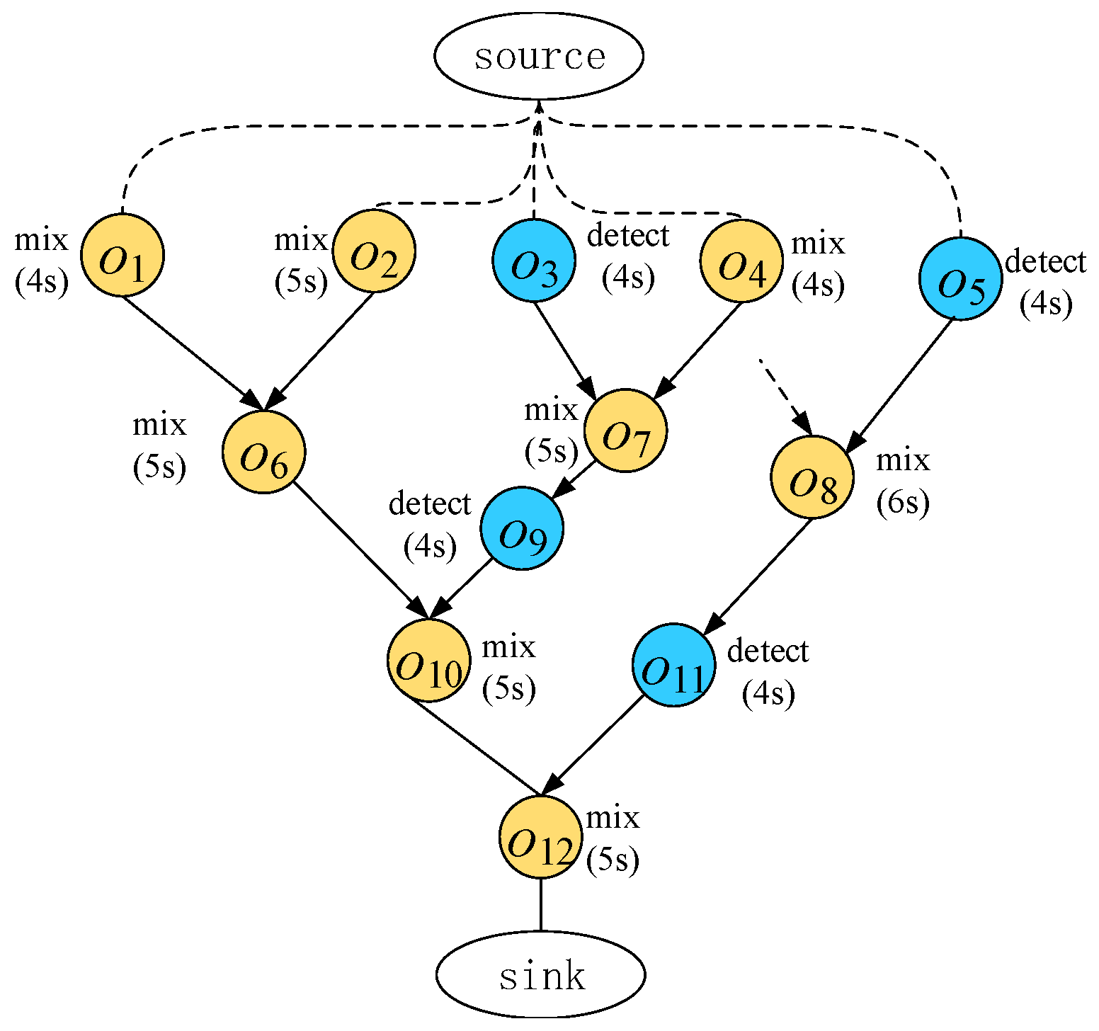
Given a sequencing graph 
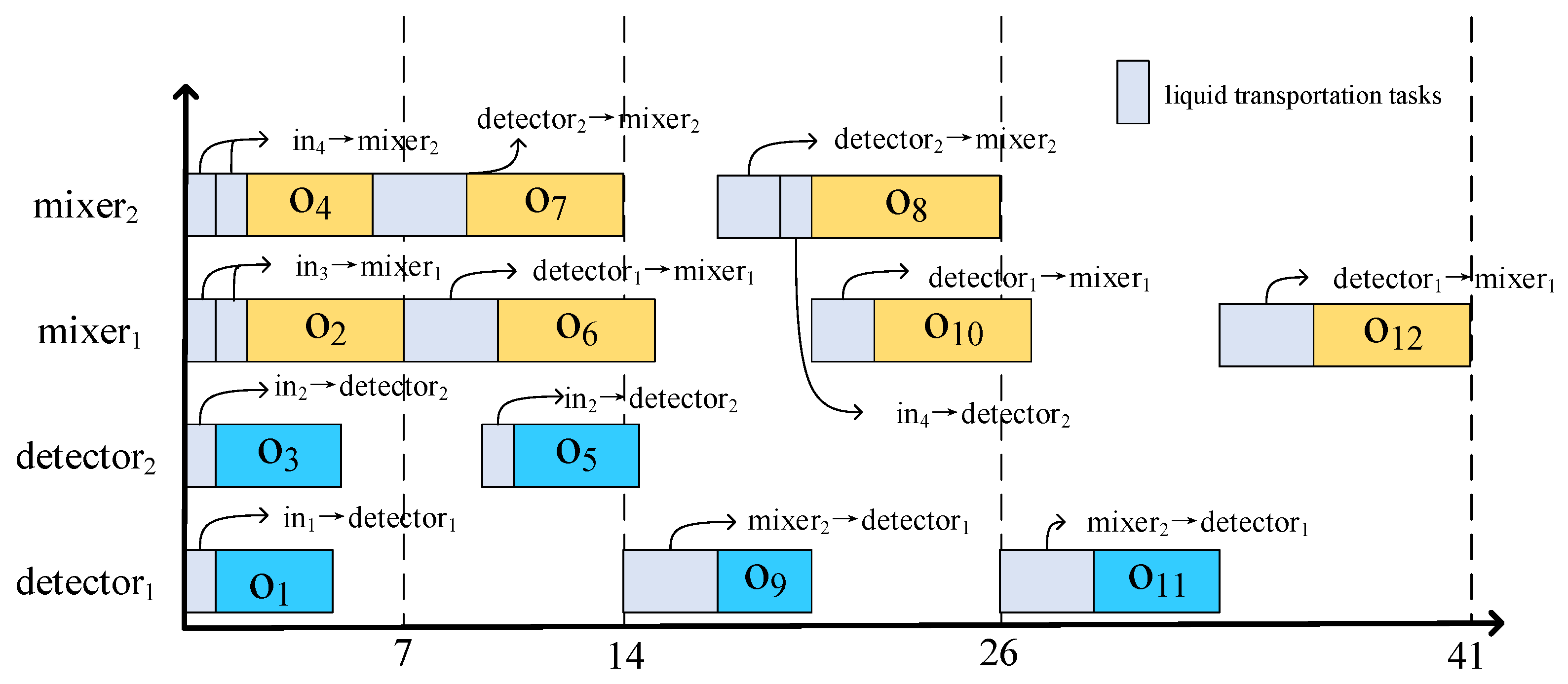
, we propose a high-level synthesis method for CFMBs, which reduces component interconnection requirements by performing time-multiplexing on flow paths based on the characteristics of the flow paths. The list scheduling algorithm is used to determine the connection between component interfaces and component interfaces and ports, as well as the binding of each liquid transportation task and storage task. Algorithm 1 gives the proposed high-level synthesis algorithm.
| Algorithm 1 High-level synthesis considering reduced component interconnection requirements. |
|
The list scheduling algorithm calculates the priority of each operation and adds all operations to the execution queue based on their priority (lines 2–3). The priority of operation is calculated as.
where is the execution time of operation , is a 0–1 binary variable that is equal to zero if operation has no child operations, and is the liquid transportation time, which is set to a fixed value [24] due to the absence of a CFMB architecture at the high-level synthesis stage. represents the set of child operations of operation .
For a given operation, different component bindings result in different component interconnection requirements. The component selection strategy in this paper is as follows: when an operation is a mixing operation and its child operation is also a mixing operation, binding to the same component of can reduce one liquid transportation task (lines 6–7), and bind() means operation is bound to component m. This is beneficial for increasing efficiency and reducing component interconnection requirements. For example, and in Figure 1 will be bound to the same component. Otherwise, the CostM function will be used to select a component with the smallest cost to bind with operation (lines 10–15). The cost of selecting a component to bind an operation is ; the calculation of is as shown in Formula (2).
where is a 0–1 binary variable and i represents the current operation , for which a component needs to be selected. If the previous operation executed on component m and the current operation are both mixing operations and have the same child operation, is equal to 1. is another binary variable which is set to 1 if component m has liquid that needs to be transported (excluding the liquid required for the current operation). is a 0–1 binary variable equal to 1 if using component m will create new component interconnections.
represents the number of flow paths that meet the following requirement: the logic flow path can transport a liquid from m to another component. is a 0–1 binary variable equal to 1 if component m cannot execute operation . represents the end time of the last task (operation execution or liquid transportation task) of component m. is the set of parent operations of operation . represents the finish time of all parent operations. The constants , and are all positive constants, and MAX_NUM is a very large parameter, indicating that component m cannot execute operation and will not be selected for operation .
After determining the binding component m for the operation, it is necessary to create liquid transportation tasks to transport the output liquid of the parent operation of to component m. If component m already has liquid, it needs to be stored (lines 16–17). Let the liquid in the component be the output liquid of operation . In the following two cases, the liquid will be transported to the next component: (1) if the sub-operation of operation is a mixing operation and one of its input liquids is already in mixer , then the liquid in component m will be transported to component ; (2) if there exists a component that satisfies the condition that it has no liquid and is of the same type as , then the liquid in component m will be transported to component . If neither of the above two cases is satisfied, the liquid will be transported to a dedicated storage unit.
A complete transportation path is required for a fluid transportation task, which also needs to be assigned a port and then scheduled for the task (lines 18–21). This paper selects the minimum cost port and component interface through the connection to form a complete transportation path using the cost function (calculated as in Formula (3)).
where and are expressed as in Formula (4) and represents a 0–1 binary variable, with and representing ports or interfaces of components. If a connection pair between and already exists, the value of is 0; otherwise, it is 1. and are constant parameters. For example, for the transportation path , if the connection pair has already been established during binding and the other three connection pairs are not yet established, then the value of , is 0 and the value of is 1.
3.2. Placement Algorithm Based on Port Relevance
Based on the accurate binding results from high-level synthesis, we place the ports according to their relevance and then determine the specific positions of components using the quadratic placer, making full use of the characteristics of fluid paths. The placement solution can reduce unnecessary detours in the routing and achieve a more optimal CFMB architecture. Algorithm 2 gives the proposed placement algorithm.
| Algorithm 2 Placement algorithm based on port relevance |
|
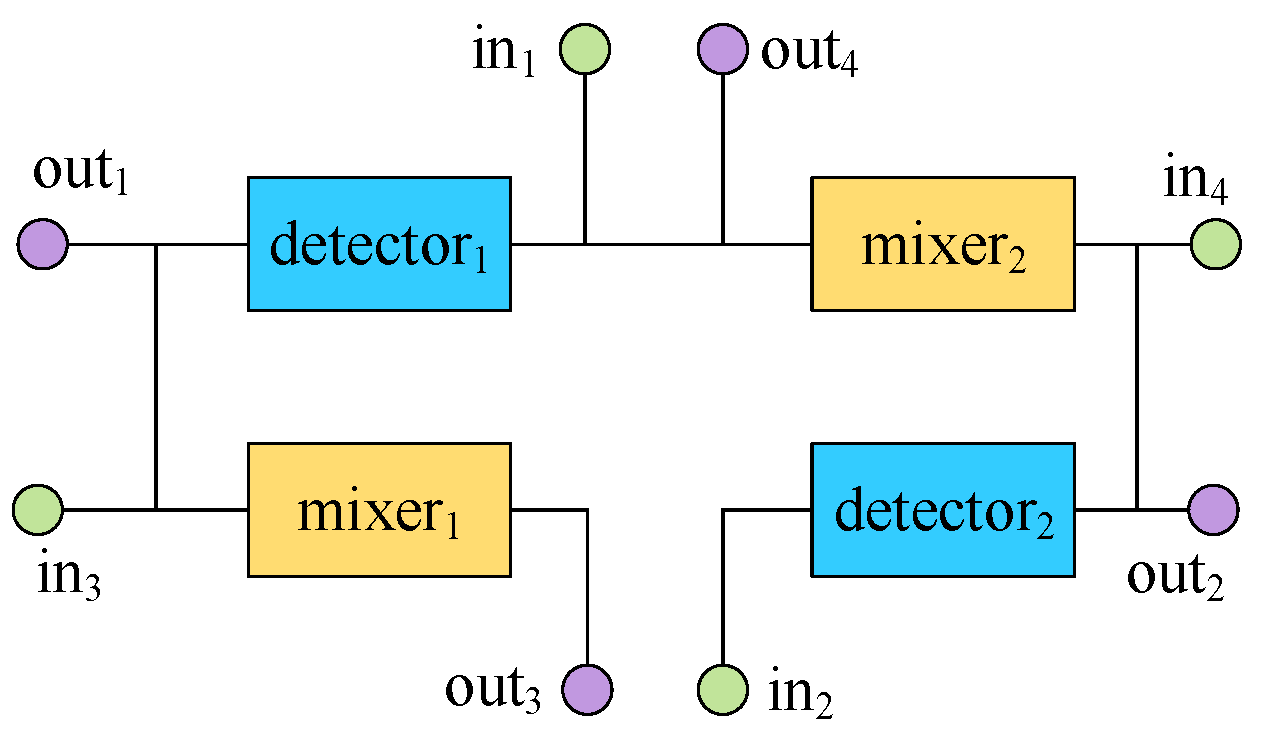
Based on the connection pairs obtained in the high-level synthesis stage, the correlation coefficient between any two ports and can be calculated according to Formula (5). For the binding scheme shown in Table 4, there are five connection pairs between component and component , which are (1) ; (2) ; (3) ; (4) ; (5) . The position of the ports and connection pairs determines the position of the components; interface B of is connected to both output port and interface A of , while interface A of is connected to input port , as shown in Figure 5 and Figure 7. If the distance between port and port is reduced, the distance between interface B of and interface A of can also be reduced, and then port and port are said to have a correlation coefficient R(, ). Ports with high correlation coefficients will be placed adjacent to each other in CFMBs.
In Formula (5), represents the flow path of the liquid from the input port to the component or from the component to the output port. Furthermore, the flow path of is . only contain two connect pairs, which are and , where and represent the interfaces of the component. represents the flow path of the liquid from one component to another; it passes by two components. can be used to transport a liquid from one component to another component and contains three connect pairs. When the i-th path of uses and as input and output ports, it is equal to 1; otherwise, it is 0. Assuming the connection pair formed by the two component interfaces of the j-th path of is and if both and - exist in the connection pair formed during the high-level synthesis stage, is equal to 1, ; otherwise, it is 0.
For the set of flow paths shown in Table 5, the first flow path uses as the input port and as the output port, so , and likewise . For the fifth flow path, there are connection pairs , and in the existing connection pairs, there are connection pairs and , so .
Table 5.
The set of flow paths.
Based on the correlation between the ports, the relative position of the components can be determined (lines 2–14), the port is placed on a straight line from left to right, and represents the port’s left and right position on the straight line. The initial distance between the ports is then randomly generated (line 15), represents the distance between the i-th and the -th port placed on the line. With the relative position of the ports and the distance between them, the ports are first placed on a straight line with a length of . Folding the line into a rectangle gives the coordinates of the ports. The x-coordinate of the port is calculated by Formula (6), and the y-coordinate can be calculated in the same way (line 18).
where represents the distance between the i-th port and the -th port placed on the straight line. w is the width of the biochip, h is the height of the biochip, and .
Ports are placed around the edges of CFMBs; when we know the coordinates of the ports, the quadratic placer estimates the wire length through a cost function and calculates the component coordinates by calculating for the minimum value of . Since the obtained solution may cause component overlap, a legalization step is required to eliminate overlap. The two dimensions of are considered separately and can be divided into x and y parts. The calculation of is shown in Formula (7).
where represents the set of connection pairs, represents the set of connection pairs formed by ports and component interfaces, and represents the set of connection pairs formed by component interfaces. represents the x-coordinate of the i-th port in the set , represents the x-coordinates of the center point of the i-th component in the set , and represents the offset of the component interface in the horizontal direction relative to the center point of the connection pair. If the component is horizontally placed and the interface is on the left side of the component, its value is -, and if it is on the right side, its value is , where width is the width of the corresponding component. If the component is vertically placed, its value is 0. represents the horizontal coordinate of the j-th connection of with respect to the first component, while represents the horizontal coordinate of the j-th connection of with respect to the second component. Likewise, we obtain . By taking partial derivatives and setting them all to zero, we can obtain a matrix equation. Solving this equation will obtain the coordinates of each component.
In this paper, the distance between ports is initialized by a random algorithm, and the coordinates of each port are obtained using Formula (5). Then, the orientation of the component and the offset between the component interface and the component center are calculated as follows: Let be the port with the most connections to interface A of component m among all flow paths, and let be the port with the most connections to interface B of component m among all flow paths. If and , then component m is placed horizontally. Then, the offset of interface A relative to the component center is ( / 2, 0), while the offset of interface B relative to the component center is ( / 2, 0), where and are the horizontal coordinates of ports and , and and are the vertical coordinates of ports and . is the width of component m. The offsets of other component interfaces relative to the center point can be obtained in a similar way. The coordinates of the components are obtained through the quadratic placer and legalized (line 19). After legalization, the half-perimeter wire length of the placement can be obtained (lines 20–21). After multiple iterations, the solution with the smallest half-perimeter wire length is selected (lines 22–25). There are many mature placement legalization methods in VLSI. In this paper, the method proposed in [27] is used to legalize the generated placement, which can quickly calculate optimal non-overlapping placement solutions.
3.3. Conflict-Aware Routing Algorithm
Based on the binding and scheduling results obtained in the high-level synthesis stage and the positions of ports and components obtained in the placement stage, the specific locations of channels in the CFMB’s architecture can be determined by routing. In order to increase the execution time of bioassays, this paper uses the minimum conflict routing algorithm proposed in [24] to route CFMBs. However, since [24] assumes the use of implicit ports, its routing algorithm cannot be directly applied to the routing in this paper. Therefore, we modify the routing algorithm in [24] to perform the routing. The specific algorithm is shown in Algorithm 3.
| Algorithm 3 Conflict-aware routing algorithm |
|
Consistent with [24], we implement minimum conflict routing based on the A* algorithm and use grids to partition the routing area. Initially, the set of time slots for each grid is set to an empty set. Here, is the number of grids, is the number of liquid transport tasks, is the start time of the j-th liquid transport task obtained in the high-level synthesis stage, is the transport time of the j-th liquid transport task obtained in the high-level synthesis stage, and the transport channel of the task passes through the i-th grid.
Unlike [24], the flow path in this article is composed of multiple connection pairs, and we need to route each connection pair in the flow path during routing. In addition, a liquid transportation task is associated with multiple connection pairs. Due to the time-division multiplexing of the flow paths and connection pairs in the high-level synthesis stage, a connection pair may be bound to multiple liquid transportation tasks. Therefore, when routing the connection pairs associated with a liquid transportation task, some of the connection pairs may have already been routed. In this case, routing is not necessary for those already routed connection pairs. For the connection pairs that have not been routed, the A* algorithm is used for routing (lines 6–8). After routing is completed, the time slot of each grid unit used by the flow path is updated.
When using the A* algorithm to route the connection pair CP of liquid transport task , the cost value Cost(k) of grid cell is calculated using Formula (8).
where is the distance from the routing start point to grid cell , is the Manhattan distance from grid cell to the routing end point, and is the sum of times that overlap occurs between the time slots in set and the scheduling time of liquid transport task in grid cell .
4. Experimental Results
The algorithms described in this paper have been implemented in C++. All experiments were conducted in a Windows environment using a 2.10 GHz CPU and 8 GB of memory. Our approach replicates the experiments conducted in reference [24]. However, it should be noted that the approach in reference [24] assumes implicit ports, providing each component with implicit input and output ports that are not explicitly modeled in the CFMB’s architecture. This simplifies the connection pairs between component interfaces and ports but may not be suitable for large-scale CFMB architectures. As [24] assumes the presence of implicit ports, it did not consider the ports in high-level synthesis. So, we address the component interconnect requirements by assigning the earliest available port to each liquid task during the high-level synthesis stage. The proposed algorithm in this paper consists of two main components: the high-level synthesis algorithm, which takes into account the component interconnection requirements as described in Section 3.1, and the physics design algorithm based on port correlation, introduced in Section 3.2 and Section 3.3. To assess the effectiveness of the algorithm, the routing method outlined in Section 3.3 is utilized, while rescheduling is performed using the method proposed in [28].
Eight benchmarks were used to verify the proposed method, where IVD1-IVD3 (in vitro diagnostics) and PCR are real-life bioassays. IVD1-IVD3 performs tests on human samples (blood, body fluids, tissues, etc.). In these assays, different types of human physiological fluids are sampled and injected into a chip for the measurement of glucose, lactate, pyruvate, and glutamate [29]. PCR (polymerase chain reaction) is DNA replication outside the organism, enabling amplification of minute DNA quantities. Here, we use the mixing phase of PCR as a test case to evaluate the proposed algorithm [30]. sy10–sy25 are synthesis benchmarks, and each benchmark consists of various operations, such as heating, mixing, detecting, and filtering.
The second column of Table 6 lists the parameters for each input test case, where represents the number of operations in the biochemical reactions and represents the number of each component type (mixer, heater, filter, detector). The column “Grid” lists the initial sizes of grids for physical design (10 mm/grid unit). After experimentation, the remaining constant parameters are set as follows: , = 1.0, and = 1.5.
Table 6.
Comparison of experimental results of two algorithms in high-level synthesis.
4.1. Validation of the Effectiveness of the Proposed High-Level Synthesis Algorithm
We present a high-level synthesis algorithm that takes component interconnect requirements into consideration. The algorithm efficiently schedules operations by employing the list scheduling algorithm and incorporates time-division multiplexing on existing flow paths.
Table 6 shows a comparison of the proposed algorithm with the high-level synthesis algorithm in [24]. Compared with the high-level synthesis algorithm in [24], our algorithm optimizes the average biochemical reaction execution time by 2.77% and the average number of connection pairs by 35.34%. Table 6 shows that the reuse of flow paths in this paper does not affect the execution efficiency of the biochip and significantly optimizes the number of connection pairs. We use the placement algorithm proposed in Section 3.2 to place two inputs, which are generated by two different high-level synthesis algorithms. We employ the routing method proposed in [24] for routing. Table 7 shows that due to the optimization of the number of connection pairs, the average number of intersections is optimized by 19.07% and the total channel length is optimized by 15.27% when using the same placement and routing methods.
Table 7.
Comparison of experimental results using the same placement for different high-level synthesis algorithms.
4.2. Validation of the Effectiveness of the Proposed Placement Algorithm
To verify the effectiveness of the placement algorithm proposed in this paper, we apply the placement algorithm proposed in Section 3.2 and the placement algorithm in [24] to the binding and scheduling results output by the high-level synthesis algorithm proposed in Section 3.1, and used the routing method described in Section 3.3 for routing. Ref. [24] utilized a simulated annealing algorithm for component placement. However, it did not consider the ports in the placement. It solely determined the positions of the components. Since the ports are located at the edges of CFMBs, for fair comparison, the placement algorithm of [24] that we reproduced incorporates the placement of ports into the simulated annealing search. In the original paper, the estimated length of flow channels between components was based on the distance between their center points. In this study, we estimate the length between ports and component center points as the Manhattan distance, taking into account that the ports are connected to the components via flow channels. By implementing a finer-grained placement during the placement phase, we provide specific length estimations for the Manhattan distance between component interfaces or between ports and component interfaces. Moreover, we consider the relevance of ports in influencing the placement results, resulting in improved placement. The experimental results are shown in Table 8, which shows that, on average, the placement algorithm proposed in this paper optimizes the routing solution; the number of intersections has been optimized by 7.54% and the total channel length by 8.65%.
Table 8.
Comparison of experimental results using the same high-level synthesis and different placements.
4.3. Validation of the Effectiveness of the Architecture Synthesis
To validate the effectiveness of the architecture synthesis method proposed in this paper, we use the algorithms proposed in Section 3.1 and Section 3.2 for high-level synthesis and placement, and used the algorithm in Section 3.3 for routing. The compared algorithms are the high-level synthesis and placement algorithm and the routing algorithm in [24]. The experimental results are shown in Table 9. It can be seen that our method achieves a 24.30% reduction in the number of intersections, with an average reduction of 21.71% in the total channel length. Since there is no channel information at the high-level synthesis stage and it is impossible to accurately estimate the time required for liquid transport or predict conflicts between liquid transport tasks, rescheduling is also needed to determine the time for each transport task and the execution time of biochemical reactions. Table 9 shows the rescheduling results of this paper and those in [24]. By reducing the number of flow paths and connection pairs, performing time-division multiplexing on flow paths in the high-level synthesis stage, and reducing the number of intersections, conflicts between liquid transport tasks caused by passing through the same intersection or using the same channel are reduced, thus improving the efficiency of CFMBs. On average, the total execution time of biochemical reactions is optimized by 18.39%. The trade-offs associated with reducing the execution time are multifaceted and warrant careful consideration; while our proposed method does achieve a reduction in execution time, this sometimes comes at the expense of an increased design complexity and potentially higher initial setup costs due to the fine-grained optimization process.
Table 9.
Comparison of experimental results of the proposed architecture synthesis method and [24].
5. Conclusions
In this paper, we have proposed an innovative architectural synthesis method for continuous-flow microfluidic biochips with a keen focus on optimizing connection pairs. In the high-level synthesis stage, by performing time-division multiplexing on flow paths, the binding and scheduling results with reduced component interconnect requirements are obtained, which helps reduce the total channel length and the number of intersections. At the placement stage, a strategy based on port correlation is proposed to place ports according to the characteristics of flow paths, and then components are placed using a quadratic wire length minimization algorithm, which helps reduce the total channel length. Furthermore, conflict-aware routing is introduced to generate flow paths, which helps reduce the execution time. Experimental results on multiple benchmarks demonstrate the effectiveness of our method. Compared with the existing work, the proposed algorithm obtains average reductions of 35.34% in connection pairs, 24.30% in flow-channel intersections, 21.71% in total flow-channel length, and 18.39% in the execution time of bioassays. Moreover, we anticipate that collaborations with biochip manufacturers and research laboratories will facilitate the testing of our algorithms on physical microfluidic biochips, thereby bridging the gap between theoretical results and real-world applications. Future research will delve into the integration of our method in time-constrained scenarios, explore the potential for automation in larger-scale CFMBs, and evaluate the adaptability of our algorithm in the face of evolving bioassay complexities.
Author Contributions
Conceptualization, X.H. and Z.C. (Zhisheng Chen); methodology, X.H., Z.C. (Zhisheng Chen) and G.L.; software, X.H.; validation, X.H. and Z.C. (Zhisheng Chen); formal analysis, X.H. and Z.C. (Zhisheng Chen); investigation, X.H. and Z.C. (Zhisheng Chen); resources, G.L.; data curation, X.H. and Z.C. (Zhisheng Chen); writing—original draft preparation, X.H.; writing—review and editing, G.L., Z.C. (Zhisheng Chen) and Z.C. (Zhen Chen). All authors have read and agreed to the published version of the manuscript.
Funding
This work was partially supported by the National Natural Science Foundation of China under Grant No. 62372109 and the Fujian Natural Science Funds under Grant No. 2023J06017.
Data Availability Statement
The data presented in this study are available on request from the corresponding author.
Conflicts of Interest
The authors declare no conflict of interest.
References
- Convery, N.; Gadegaard, N. 30 years of microfluidics. Micro Nano Eng. 2019, 2, 76–91. [Google Scholar] [CrossRef]
- Zhu, Z.; Zeng, F.; Pu, Z.; Fan, J. Conversion electrode and drive capacitance for connecting microfluidic devices and triboelectric nanogenerator. Electronics 2023, 12, 522. [Google Scholar] [CrossRef]
- Tarek, H.; Aly, H.; Eisa, S.; Abul-Soud, M. Optimized deep learning algorithms for tomato leaf disease detection with hardware deployment. Electronics 2022, 11, 140. [Google Scholar] [CrossRef]
- Fathimathul, R.P.P.; Moustafa, A.S.U.M.A.; Ali, M.A.S. Detecting plant disease in corn leaf Using efficientNet architecture—An analytical approach. Electronics 2023, 12, 1938. [Google Scholar]
- Luna-Benoso, B.; Martínez-Perales, J.C.; Cortés-Galicia, J.; Flores-Carapia, R.; Silva-García, V.M. Detection of diseases in tomato leaves by color analysis. Electronics 2021, 10, 1055. [Google Scholar] [CrossRef]
- He, H.; Yuan, Y.; Wang, W.; Chiou, N.R.; Epstein, A.J.; Lee, L.J. Design and testing of a microfluidic biochip for cytokine enzyme-linked immunosorbent assay. Biomicrofluidics 2009, 3, 022401. [Google Scholar] [CrossRef] [PubMed]
- Thorsen, T.; Maerkl, S.J.; Quake, S.R. Microfluidic large-scale integration. Science 2002, 298, 580–584. [Google Scholar] [CrossRef] [PubMed]
- Fan, H.C.; Blumenfeld, Y.J.; Chitkara, U.; Hudgins, L.; Quake, S.R. Noninvasive diagnosis of fetal aneuploidy by shotgun sequencing DNA from maternal blood. Proc. Natl. Acad. Sci. USA 2008, 105, 16266–16271. [Google Scholar] [CrossRef]
- Chin, C.D.; Laksanasopin, T.; Cheung, Y.K.; Steinmiller, D.; Linder, V.; Parsa, H.; Wang, J.; Moore, H.; Rouse, R.; Umviligihozo, G.; et al. Microfluidics-based diagnostics of infectious diseases in the developing world. Nat. Med. 2011, 17, 1015–1019. [Google Scholar] [CrossRef]
- Zheng, B.; Roach, L.S.; Ismagilov, R.F. Screening of protein crystallization conditions on a microfluidic chip using nanoliter-size droplets. J. Am. Chem. Soc. 2003, 125, 11170–11171. [Google Scholar] [CrossRef]
- Einav, S.; Gerber, D.; Bryson, P.D.; Sklan, E.H.; Elazar, M.; Maerkl, S.J.; Glenn, J.S.; Quake, S.R. Discovery of a hepatitis C target and its pharmacological inhibitors by microfluidic affinity analysis. Nat. Biotechnol. 2008, 26, 1019–1027. [Google Scholar] [CrossRef] [PubMed]
- Liu, C.; Xue, N.; Cai, H.; Sun, J.; Qi, Z.; Zhao, P.; Xiong, F.; Geng, Z.; Jiang, L.; Li, L. Nanoparticles enhanced self-driven microfludic biosensor. Micromachines 2020, 11, 350. [Google Scholar] [CrossRef] [PubMed]
- Long, X.; Ishii, I.; Gu, Q. CellNet: A lightweight model towards accurate LOC-based high-speed cell detection. Electronics 2022, 11, 1407. [Google Scholar] [CrossRef]
- Rogers, J.A.; Nuzzo, R.G. Recent progress in soft lithography. Mater. Today 2005, 8, 50–56. [Google Scholar] [CrossRef]
- Liu, G.; Huang, H.; Chen, Z.; Lin, H.; Liu, H.; Huang, X.; Guo, W. Design automation for continuous-flow microfluidic biochips: A comprehensive review. Integration 2022, 82, 48–66. [Google Scholar] [CrossRef]
- Perkel, J.M. Life science technologies: Microfluidics—Bringing new things to life science. Science 2008, 322, 975–977. [Google Scholar] [CrossRef]
- Huang, X.; Ho, T.Y.; Guo, W.; Li, B.; Chakrabarty, K.; Schlichtmann, U. Computer-aided design techniques for flow-based microfluidic lab-on-a-chip systems. ACM Comput. Surv. 2021, 54, 1–29. [Google Scholar] [CrossRef]
- Minhass, W.H.; Pop, P.; Madsen, J. System-level modeling and synthesis of flow-based microfluidic biochips. In Proceedings of the 4th International Conference on Compilers, Architectures and Synthesis for Embedded Systems, Taipei, Taiwan, 9–14 October 2011; pp. 225–234. [Google Scholar]
- Liu, C.; Li, B.; Yao, H.; Pop, P.; Ho, T.Y.; Schlichtmann, U. Transport or store? Synthesizing flow-based microfluidic biochips using distributed channel storage. In Proceedings of the 54th Annual Design Automation Conference, Austin, TX, USA, 18–22 June 2017; pp. 1–6. [Google Scholar]
- Wang, Q.; Zou, H.; Yao, H.; Ho, T.Y.; Wille, R.; Cai, Y. Physical co-design of flow and control layers for flow-based microfluidic biochips. IEEE Trans. -Comput.-Aided Des. Integr. Circuits Syst. 2017, 37, 1157–1170. [Google Scholar] [CrossRef]
- Zhu, Y.; Huang, H.; Lin, H.; Chen, W.; Liu, G.; Xu, N.; Huang, X. Sequence-pair-based flow-layer physical design algorithm for continuous-flow microfludic bioChips. J. Comput. Aided Des. Comput. Graph. 2022, 34, 535–544. [Google Scholar]
- Minhass, W.H.; Pop, P.; Madsen, J. Synthesis of biochemical applications on flow-based microfluidic biochips using constraint programming. In Proceedings of the 2012 Symposium on Design, Test, Integration and Packaging of MEMS/MOEMS, Cannes, France, 25–27 April 2012; pp. 37–41. [Google Scholar]
- Dinh, T.A.; Yamashita, S.; Ho, T.Y.; Hara-Azumi, Y. A clique-based approach to find binding and scheduling result in flow-based microfluidic biochips. In Proceedings of the 2013 18th Asia and South Pacific Design Automation Conference, Yokohama, Japan, 22–25 January 2013; pp. 199–204. [Google Scholar]
- Huang, X.; Guo, W.; Chen, Z.; Li, B.; Ho, T.Y.; Schlichtmann, U. Flow-based microfluidic biochips with distributed channel storage: Synthesis, physical design, and wash optimization. IEEE Trans. Comput. 2021, 71, 464–478. [Google Scholar] [CrossRef]
- Huang, X.; Ho, T.Y.; Li, Z.; Liu, G.; Wang, L.; Li, Q.; Guo, W.; Li, B.; Schlichtmann, U. MiniControl 2.0: Co-synthesis of flow and control layers for microfluidic biochips with strictly constrained control ports. IEEE Trans. Comput. Aided Des. Integr. Circuits Syst. 2022, 41, 5449–5463. [Google Scholar] [CrossRef]
- Huang, X.; Pan, Y.; Zhang, G.L.; Li, B.; Guo, W.; Ho, T.Y.; Schlichtmann, U. PathDriver+: Enhanced path-driven architecture design for flow-based microfluidic biochips. IEEE Trans. Comput. Aided Des. Integr. Circuits Syst. 2022, 41, 2185–2198. [Google Scholar] [CrossRef]
- Spindler, P.; Schlichtmann, U.; Johannes, F.M. Abacus: Fast legalization of standard cell circuits with minimal movement. In Proceedings of the 2008 International Symposium on Physical Design, Portland, OR, USA, 13–16 April 2008; pp. 47–53. [Google Scholar]
- Minhass, W.H.; McDaniel, J.; Raagaard, M.; Brisk, P.; Pop, P.; Madsen, J. Scheduling and fluid routing for flow-based microfluidic laboratories-on-a-chip. IEEE Trans. Comput. Aided Des. Integr. Circuits Syst. 2017, 37, 615–628. [Google Scholar] [CrossRef]
- Su, F.; Chakrabarty, K. Module placement for fault-tolerant microfluidics-based biochips. ACM Trans. Des. Autom. Electron. Syst. 2004, 11, 682–710. [Google Scholar] [CrossRef]
- Zhang, T.; Chakrabarty, K.; Fair, R.B. Microelectrofluidic Systems: Modeling and Simulation; CRC Press: Boca Raton, FL, USA, 2018. [Google Scholar]
Disclaimer/Publisher’s Note: The statements, opinions and data contained in all publications are solely those of the individual author(s) and contributor(s) and not of MDPI and/or the editor(s). MDPI and/or the editor(s) disclaim responsibility for any injury to people or property resulting from any ideas, methods, instructions or products referred to in the content. |
© 2024 by the authors. Licensee MDPI, Basel, Switzerland. This article is an open access article distributed under the terms and conditions of the Creative Commons Attribution (CC BY) license (https://creativecommons.org/licenses/by/4.0/).