Abstract
In the last three decades, the development of new electricity-generation strategies based on renewable energy has been promoted, which has made it possible to offset the increase in electricity consumption, reduce production costs, and positively impact climate change. These new-generation strategies are based on distributed generation (DG) at different points of the electrical power system, which has economic, social, and environmental impacts by reducing greenhouse gas emissions. The new concept of an electric microgrid, which is an integrated energy generation and management system with autonomous capacity, allows efficient production and consumption, with alternating current (AC) and direct current (DC) microgrids being available. This work presents a topology of direct current microgrids for island mode operation, which aims to supply electricity to variable and constant power loads (CPLs), as well as for the autonomous charging and discharging of batteries. To achieve this objective, a microgrid model is developed, current and voltage control loop controllers are designed, and their performance in different types of operation is analyzed. As a contribution to this work, the parasitic elements in the microgrid model are considered, and the design of the controller in the voltage loop is presented for the power supply to the local linear and non-linear loads, in addition to managing the energy coming from CPLs and controls the charge and discharge of the battery. To validate the performance of the controllers, three microgrid operation tests are carried out, which are presented in the Simulations section. In these tests, it is observed that with the PI controller in the voltage loop, the DC_Link signal presents transients with an amplitude of 5 V below and above the 200 V reference, which shows the poor performance of the controller. However, in all three tests with the modified PI-P controller, the DC_Link voltage remains constant at 200 V, with a negligible transient amplitude of almost 0 V, showing better performance.
1. Introduction
The new distributed generation (DG) strategies [1] positively impact the economic, social, and environmental aspects of a country, which is justified by considering the reduction in the energy generation and distribution costs caused by bringing the generation to consumption centers, as well as to areas where its supply through the electrical grid is not possible. In addition, polluting emissions are reduced by having renewable energies as primary generation sources. In this context, and derived from the concept of distributed generation, technological platforms known as electrical microgrids [2] are being developed, which aim to serve as an interface between the renewable energy source and the final consumer, connecting, monitoring, and controlling the resources. These microgrids can operate either connected to the public grid or in island mode. They are also classified according to the type of energy they can manage, with alternating current (AC) and direct current (DC) microgrids being available [3]. Considering this classification, this work proposes to develop a DC microgrid to supply energy to the local linear and non-linear DC loads without the need to carry out conversion processes from one type of energy to another, as is the case in AC microgrids. Furthermore, in DC microgrids, there are no problems with synchronization, the presence of harmonics, and control of the reactive power and frequency. This makes the energy generation and supply process more efficient [4].
Considering that this work focuses on the development of a direct current microgrid for island mode operation, it is important to know that its basic structure is composed of the following elements: electronic converters with different topologies [5], energy sources known as energy load constants (EPCs) [6], and storage systems [7]. This highlights the design of controllers that allow the operation of the microgrid [8]. Each of these elements has an important role in generating and managing the energy obtained by the microgrid.
This work is made up of the following sections. Section 1 presents the introduction and the state-of-the-art research. In Section 2, works related to the research are reported. In Section 3, the microgrid model development methodology is presented, considering the topology required for island mode operation. In Section 4, the controllers’ design and their implementation for this mode of operation are presented. In Section 5, the microgrid operation results are presented, and finally, Section 6 presents the conclusions and future research work.
2. Related Works
Considering the previous background, below is a summary of the state-of-the-art research related to the work presented in this research.
In [9], a model predictive control (MPC) approach is presented to address the destabilization problem and mitigate the destructive effect of CPLs, leading to a robust control approach and widening the system’s stability margin. In [10], a novel robust controller based on linear programming and Chebyshev’s theorem is presented. This robust control technique considers the Kharitonov theorem, which minimizes the total deviation from the desired performance in a closed-loop system, considering a characteristic polynomial family. The proposed controller’s purpose is to strictly regulate the DC bus voltage, ensuring the MG stability due to the power variation effects on the CPLs. In [11], an overview of advanced control technologies for bidirectional DC/DC converters in DC microgrids is presented. First, the stability problem caused by the CPL is analyzed, which motivates the use of this control technique, including predictive control, rollback control, sliding mode control, control based on passivity, disturbance estimation techniques, intelligent control, and non-linear modeling. In [12], the authors describe how current mode control provides a suitable solution for regulating boost converters with constant power loads. The corresponding small-signal transfer functions are calculated for the different microgrid controller designs. Furthermore, the authors show how charging the current feed-forward presents an effective way to improve the charging power transient responses. Ref. [13] proposes an autonomous control scheme for a bidirectional direct current converter (BDC) in a DC microgrid. The proposed scheme is based on V2-P droop control and unifies bus voltage regulation and power regulation in the control structure. Therefore, a smooth transition between the various operating modes can be achieved, avoiding various operating-mode change detection elements and improving the system stability. The proposed controller is completely decentralized, which reduces the communication dependency and improves the microgrid reliability. In [14], the authors propose a bidirectional DC/DC converter control scheme for an energy storage system (ESS) that solves the problems associated with microgrid operation mode changes. The proposed control scheme provides autonomous and smooth switching, thereby reducing the dependency on communication with the central controller and improving the system’s reliability. In [15], the novel concept of a highly versatile smart power electronics interface for the rapid implementation of residential DC microgrids is presented. The proposed system has bidirectional power flow control capabilities over a wide operating voltage range and high efficiency, which allows the system to be compatible with most commercial 60- and 72-cell PV modules, as well as efficient charge/discharge control of the 24 V and 48 V battery energy storage system, using the same platform hardware. The authors of [16] provide a comprehensive review of multiple architectures and topologies of power electronic converters and a detailed classification and analysis of the advantages and disadvantages of these topologies. This work serves as a suitable review for researchers/engineers who want to study the voltage balance field in DC grid bipolar and promote the innovation of their power electronics-enabled solutions. In [17], the DC microgrid is controlled with variable energy generation and storage. A three-level autonomous control strategy for DC microgrids is proposed. The common DC voltage detection recognizes the system’s operating state and variation, activating transitions between different operating levels. The authors of [18] address a voltage-control and energy-management strategy for a grid-connected DC microgrid and an isolated DC microgrid with hybrid energy resources. In the island mode, a control and management strategy is designed for a backup diesel generator (DG), a renewable energy source (RES), and an energy storage system that plays a vital role in maintaining the microgrid bus voltages within the established limits. The authors of [19] present a robust control method review for hybrid AC and DC microgrids with different topologies and types of interconnections to conventional power systems. The main objectives of the proposed control methods are comparatively analyzed for different microgrid types.
Considering all presented previously, this work focuses on developing a microgrid model considering a bidirectional Buck-Boost DC power converter and the proposed controller design. The controller design for the voltage loop is highlighted, considering that it must operate in island mode, and its objective is to ensure the voltage signal amplitude and its regulation effectively with the established power supply quality criteria [20].
Considering that this work focuses on the development of a direct current microgrid for island mode operation, it is essential to know its basic structure made up of the following elements: electronic converters with different topologies [21], energy sources known as loads of constant power (CPL) [22] and storage systems [23], highlighting the effective controller design that allows good microgrid performance [4,11]. Each of these elements plays a vital role in generating and managing energy obtained by the microgrid. Figure 1 shows the schematic of a direct current microgrid for island mode operation.
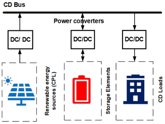
Figure 1.
DC microgrid schematic in island mode operation.
An essential element in the DC microgrid structure is the power electronic converter used to manage the energy obtained through the renewable source. A bidirectional Buck-Boost converter is used for these applications [11]. This topology is selected considering that the current has bidirectional behavior—that is, it can leave and enter the converter, possibly charging and discharging the battery when necessary and delivering and consuming power from the source if it is required. Another essential feature of this converter is that it allows the input voltage (VDC_Link) to be increased or reduced concerning the output voltage, allowing the power flow to change from one quadrant to another. Therefore, the battery can be charged and discharged. Also, an essential element in the configuration of DC microgrids is constant power loads (CPLs) [22], defined as the set of other energy sources that feed the microgrid and other batteries that are not electrically connected to its primary battery. The CPLs behave as non-linear elements and are represented as negative impedances in the microgrid structure. Figure 2 shows the topology of this converter as part of the DC microgrid. The battery and the equivalent constant power load CPL are also represented in this diagram.
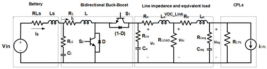
Figure 2.
DC microgrid schematic diagram with bidirectional Buck-Boost power electronic converter.
The microgrid operating parameters are described below.
- , the energy storage element (battery).
- , the battery current.
- , the converter’s main switches.
- , the high-frequency diode, which serves to control current circulation.
- , the converter’s main inductor.
- , the converter’s output filter capacitor.
- , the constant power load impedance.
3. DC Microgrid Modeling
In this section, the microgrid model is obtained, represented by the schematic diagram in Figure 3. The transistors (S1 and S2) comprise the bidirectional Buck-Boost power electronic converter. The operation of these transistors is non-linear; therefore, to model this converter, it is necessary to linearize these elements to obtain transfer functions that allow designing controllers for the different microgrid loops.
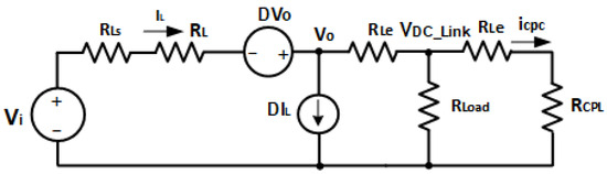
Figure 3.
DC microgrid large signal equivalent model.
For the converter non-linear elements linearization, there are the following methods: state-space averaging and the PWM switch method [24]. This work uses the PWM switch method mainly because its approximation is more precise and allows the analysis of stability problems that state-space averaging cannot do. This method allows the averaged variable to be decomposed into the sum of the great signal variable or the value at the operating point and the small signal variable, representing the noise or deviation that the real signal has concerning the desired value.
Considering the previous considerations, Figure 3 presents the microgrid large-signal linearized equivalent diagram. It was assumed that, in direct current, the inductances behave like an impedance of zero value or a short circuit, and the capacitor is an infinite value impedance or an open circuit.
With these considerations and applying Kirchhoff’s voltage law (LTK), around the input voltage and up to the converter output capacitor, the following is obtained (1):
Grouping terms and solving are obtained (2):
The following is obtained (3) by applying Kirchhoff current law (LCK) in the node:
To obtain the large signal component of the duty cycle, is calculated, which is obtained by applying Kirchhoff’s current law to the converter output voltage node (4).
By grouping terms (5),
Substituting in (2), the following is obtained (6):
By regrouping terms and applying the quadratic equation, (7) is obtained, which represents the duty cycle.
After analyzing the large signal model that allows for the duty cycle (), the small-signal model is now obtained, considering only the disturbances or deviations in the microgrid operating point. This model includes battery impedance parasitic elements of the converter inductor and the capacitor at the microgrid input. This small-signal model allows obtaining the microgrid transfer functions to design the controllers necessary for its operation. Figure 4 represents the microgrid’s small-signal model.
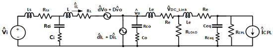
Figure 4.
DC microgrid small-signal model.
3.1. Current Loop Transfer Function
Using the small-signal model, the microgrid current loop transfer function defined as () [25] can be obtained. This function is the relationship between the converter inductor current and the duty cycle. It is obtained considering that the input voltage small signal component is zero, as shown by (8).
This transfer function is used to design the converter current control loop and is calculated by analyzing the left side of the small microgrid model, which is presented in Figure 4.
Where the total input impedance () is calculated by analyzing the left side of Figure 4 and can be written as (9).
and the equivalent impedance at the converter output () is presented by (10).
Likewise, the converter output impedance () is presented by (11).
After analyzing the super mesh diagram in Figure 4, we obtained a result of (12).
3.2. Voltage Loop Transfer Function
Using the current loop transfer function, the microgrid’s voltage loop transfer function can be found, defined as () which is the microgrid’s ratio and the duty cycle [26]. This transfer function is used to design the microgrid’s voltage loop controller, presented in (13).
The transfer function (13) requires initial input impedance calculation (9). Applying Kirchhoff’s voltage law in the model shown in Figure 4, starting from the total input impedance toward the converter output capacitor, the equation can be written as (14).
By ordering terms (15),
Considering that
The following an be written (17).
The following is obtained by applying Kirchhoff’s current law to the node where the converter output capacitor is located (18):
4. Controller Design
Once the current loop and the voltage loop transfer functions are calculated, the controller designs for both control loops are carried out, considering that the microgrid controls the inductor current and the . For their designs, an average current control topology (ACC) is considered [27], as shown in Figure 5.
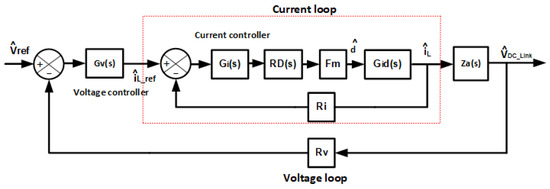
Figure 5.
Average current control (ACC) converter scheme.
- where
- is the transfer function of the current controller.
- is the transfer function of the voltage controller.
- ) is the transfer function of the current in the inductor in relation to the duty cycle.
- is the transfer function of the to the inductor current, expressed by (19).
- is the digital delay, expressed by (20).
- is the current sensor gain.
- is the voltage sensor gain.
Table 1 shows the microgrid’s operating parameter values used in the design of the controllers.

Table 1.
Microgrid parameter values.
In the controller design, a 200 V voltage is used as a reference, representing in the microgrid.
4.1. Current Control Design
The control that regulates the inductor’s current is implemented by considering the average current control scheme (ACC) [27] and a cascade control scheme [28]. For this control loop, a proportional integral control (PI) [28] is chosen, which is designed in detail below.
PI Current Controller Design
The proportional integral controller aims to obtain a system-stable response without error in a steady state. Mainly, integral action decreases and eliminates the steady-state error caused by proportional action. Integral control acts when there is a deviation between the variable and the set point, integrating this deviation over time and adding it to the proportional action. The controller design is obtained from the scheme shown in Figure 5.
Adhering to certain rules is crucial when designing the controller. For instance, the current controller should be designed with a crossover frequency 10 times lower than the Buck-Boost converter switching frequency, which is 10 kHz [29]. This means that the current loop crossover frequency should be 1 kHz. Additionally, it is advisable to consider the Nyquist stability criteria, ensuring a phase margin within the range of 50 to 90 degrees and a gain margin greater than 5 dB.
Furthermore, the temporal response overshoot to a step input should be at most 20% [28].
Considering the above, the controller’s transfer function is (21).
Figure 6 shows the open-loop Bode plot calculated with (22). This diagram shows the implemented controller frequency response, where the Nyquist stability criteria are met with a phase margin of 52.1°, a gain margin of 7.05 dB, and a crossover frequency of 1.03 kHz.
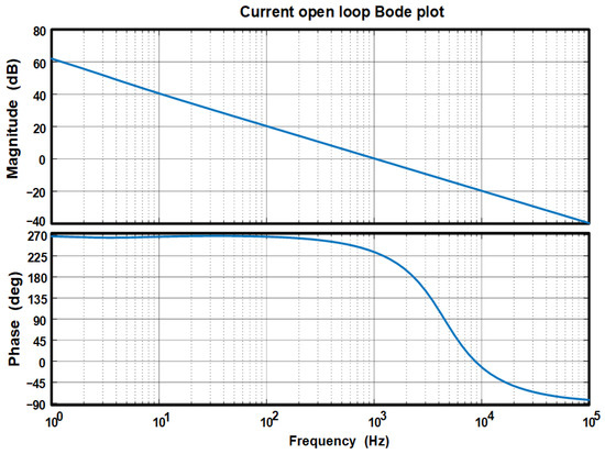
Figure 6.
Bode plot of open loop current control () using PI controller.
The closed-loop transfer function determines the transient response on a stepped input signal. It is used to design the voltage loop controller presented in (23).
Figure 7 presents the temporal response to a step input, complying with the Nyquist stability criteria. The maximum overshoot is less than 20%, and the establishment time is 1.2 ms.
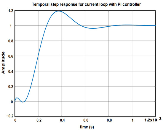
Figure 7.
Microgrid temporal response to a step input with PI controller.
4.2. Voltage Loop Controller
The voltage loop controller will be designed once the current loop controller is designed. Two controller designs are proposed for voltage lop, considering their importance for the microgrid operation. This is justified because in island mode operation, the voltage regulator must keep the constant in different operating situations, such as linear and non-linear load changes, battery charging and discharging, and CPL variations. To meet this objective, the proportional integral controller design (PI) [28] and a modified proportional integral derivative controller (modified PID controller) [28] are presented, which will be described in detail below.
The PI and PID-modified voltage loop controller designs consider a cascade configuration and the average current control (ACC) scheme used for the current control design. Therefore, this controller must have a crossover frequency lower than the crossover frequency of the current loop controller, which is 1 kHz. Furthermore, the sensing gain is determined by the Nyquist stability criteria values established in the loop control design, making it a crucial factor in the controller’s design.
For its design, the transfer function is (24):
4.2.1. PI Voltage Controller Design
The PI controller design for the voltage loop is presented in (25).
The closed-loop voltage transfer function is shown in (26).
Two control configurations are proposed for the voltage loop: PI control and modified PID control. The implementation of both controllers (25) will be presented, along with the open-loop Bode diagrams and closed-loop temporal responses, to compare their performances.
4.2.2. Modified PID Controller Design
The modified PID controller allows different control configurations to be developed using the PID controller design. Under this modified PID control scheme, the microgrid is intended to have good set-point tracking and adequate disturbance rejection, which is obtained by implementing PID control actions in the direct loop and others in the feedback loop, resulting in various control configurations such as PID-PD, PI-PD, and I-PD [28].
Taking the above into account, Figure 8 shows the equivalent block diagram of a PID control configuration subject to disturbances. This diagram shows the proportional, integral, and derivative control action parameters.
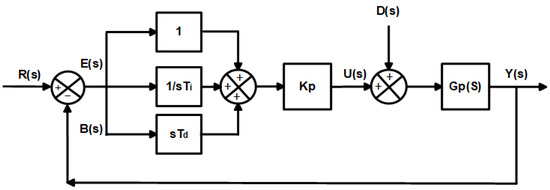
Figure 8.
PID controller equivalent block diagram.
Considering the equivalent block diagram shown in Figure 8 and the modified PID controller design advantage over a classic PID controller, a proportional integral controller can be configured in the direct loop and a proportional controller in the feedback loop. The results in a modified PI-P configuration are shown in Figure 9, which is represented by the parameters of the microgrid.
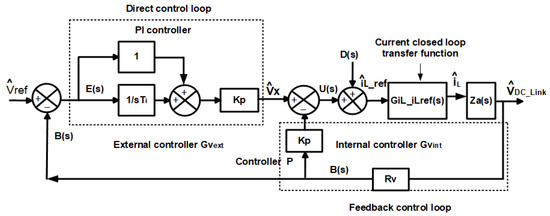
Figure 9.
PI-P controller equivalent block diagram.
In the control configuration of Figure 9, the transfer functions are obtained for the modified PI-P control design that must be implemented in the microgrid voltage loop. To obtain the closed loop transfer function that relates /Vref, it is necessary that be equal to zero. With this consideration and applying block algebra, the following is obtained (27):
where Gp = GiL_iLref(s)·Za.
On the other hand, if the reference input and the noise are considered zero, the closed-loop transfer function between the output and the disturbance , is calculated, which allows for (28).
Expression (27) calculates the direct loop control that gives the system good setpoint tracking. Likewise, expression (28) is used for the feedback loop control design, which aims for the system to have good disturbance rejection.
The method and criteria for this controller design are established, considering the modified PI-P controller’s previous transfer functions.
Design method. Considering the previous design criteria, the design method is established.
- The proportional controller () is initially designed in the internal voltage loop for a frequency lower than the frequency current loop controller (1 kHz). It is important to mention that a gain sweep () was performed in an interval of 0.3 to 1.5 for this control, aiming to validate its performance in the frequency domain and the time domain.
- Once the internal loop voltage controller () is designed, the external loop controller is designed with a control configuration for a crossover frequency lower than the internal loop controller crossover frequency, maintaining the Nyquist stability criteria mentioned in Section 4.1.
Equation (29) shows the feedback loop controller design , while (30) shows the direct loop PI control design.
Figure 10 and Figure 11 show the microgrid voltage loop PI-P controller Bode diagrams, particularly in the Bode diagram of Figure 10, which presents the implemented proportional controller behavior in the internal voltage control loop considering the gain values = 0.3, 0.6, 0.9, 1.2, and 1.5. Figure 11 shows the external control loop Bode plots obtained with the PI controller implementation, considering the internal controller gains. Particularly the modified PI-P controller stability parameters, considering its best performance, the PI controller designed for the external loop has a phase margin of 54.3°, a gain margin of 36.4 dB, and a crossover frequency of 21 Hz. The P controller designed for the internal loop has a gain of = 1.5, a phase margin of 90.1°, a gain margin of 36.2 dB, and a crossover frequency of 13.2 Hz. This diagram shows that the external loop controller has a lower crossover frequency than the internal loop, which is correct considering the hierarchical level presented by each control loop in the microgrid; in addition, both designs meet the Nyquist stability criteria.
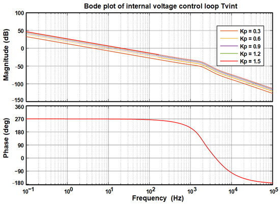
Figure 10.
Bode plot of open loop gain with controller in the internal loop of internal voltage (Pint).
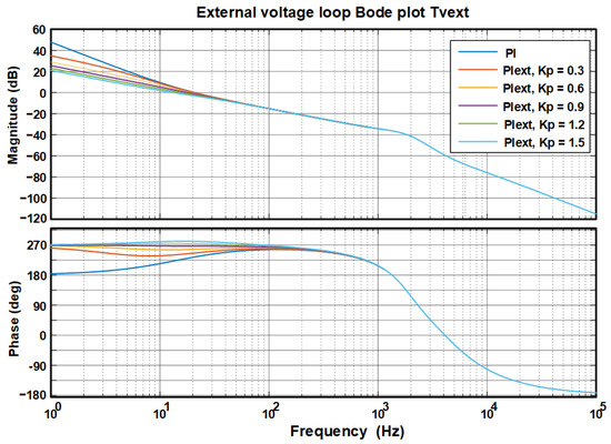
Figure 11.
Bode plot of open loop gain with PI controller in the external loop of internal voltage (PIext).
In the analysis of microgrid transient response, the closed-loop voltage transfer function is used, as shown in (27). The transient response graphs are presented in Figure 12. In this graph, the PI controller response overshoot is 22%. It contrasts with the modified PI-P controller design, where this transient response is lower for different P controller gain values designed for the internal voltage control loop, and its value is = 1.5. Therefore, the modified PI-P controller had a better performance than the PI controller, an overdamped response, and an establishment time of 0.08 s.
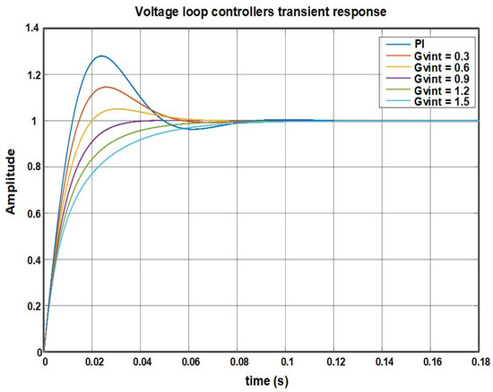
Figure 12.
Microgrid temporal response to a step input with PI and Modified PI-P controller.
5. Tests and Results Obtained by Simulations
The tests are presented through simulations on the microgrid with the controller’s implementation: PI in the current loop and a PI and modified PI-P controller in the voltage loop. The PSIMTM tool is used for the tests described below [30].
- Tests with variable local load and constant CPL power, using a PI controller in the current loop and a PI controller in the voltage loop.
- Tests with constant local load and variable CPL power, using a PI controller in the current loop and a PI controller in the voltage loop.
- Tests with linear local load, constant CPL power, and variable non-linear load, using a PI control in the current loop and a PI controller in the voltage loop.
5.1. Tests with PI Controller in the Current Loop and PI in the Voltage Loop
5.1.1. Test 1
This test is carried out by varying the local load (RLOAD) to demand power from 1 kW to 6 kW, ascending and descending with steps of load changes of 1 kW and maintaining the CPL power constant at a value of 2.4 kW. This test permits the validation of microgrid performance under load changes. The selected power values permit observing the power flow at the battery.
The test results are presented in the graphs of Figure 13, where is graphed for microgrid various load changes, while the power of the CPLs remained constant at 2.4 kW. In this graph, it is observed that the has a value of 200 V. Also, load current variations from 5 A to 30 A can be observed. An overshoot occurs in a range of 5 A to −5 A.
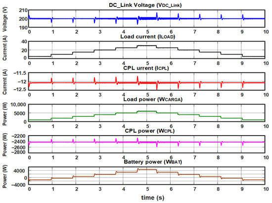
Figure 13.
Test with variable local load and constant CPL power with PI controller in the current loop and PI controller in the voltage loop.
The load current shape (ILOAD) and load power (WLOAD) signals represent the microgrid behavior when subjected to ascending and descending load transients from a value of 0.8 kW to a value above the nominal load of 7.2 kW. This test shows that the battery is discharged proportionally to the local charge variation and charged proportionally to the CPL value.
Similarly, the signals CPL’s current shapes (ICPL) and CPL’s power (WCPL) show that by varying the , the CPL current remains with constant power at −10 A and 2.3 kW, which represents good microgrid performance.
5.1.2. Test 2
This test consists of keeping the local load constant and varying the CPL power. This test is valuable since the microgrid incorporates a renewable energy source, which delivers intermittent power to the microgrid that depends on the solar radiation factor. The CPL behaves like a variable power supply.
This test considers that the load power is constant at 2 kW, and the CPL power varies between 0.8 kW, 1.2 kW, 2.4 kW, 3.6 kW, 4.8 kW, 6 kW, and 7.2 kW. The selected CPL power is used to observe the battery charging and discharging behavior. Therefore, the CPL supplies variable energy to the battery, which discharges proportionally to the value of the local charge that remains constant.
The test results are shown in the graphs of Figure 14, where the microgrid is subjected to the previously mentioned power changes of (WCPL) while the load power (WLOAD) is maintained at a constant value of 2 kW. In this test, good microgrid performance is observed since even with variations in ICPL from −5 A to −30 A and WCPL, the remains constant at 200 V.
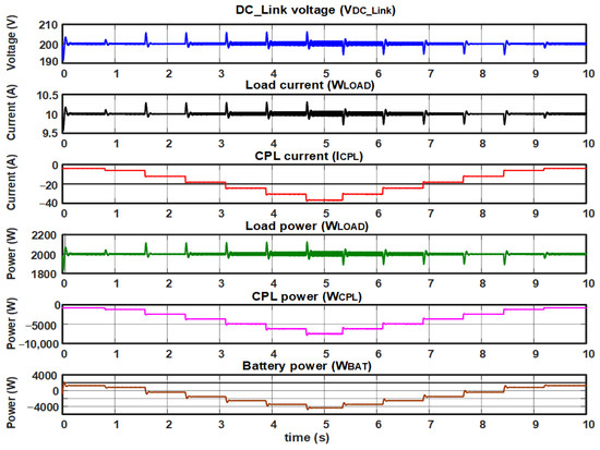
Figure 14.
Test with constant local load and variable CPL power, with PI control in the current loop and PI controller in the voltage loop.
5.1.3. Test 3
After observing the microgrid’s behavior under linear load changes and CPL power changes, it is necessary to validate its performance by feeding non-linear loads. Most electrical equipment behaves as non-linear elements when adding semiconductors to its structures. This test selects a non-linear load power of one-third of the microgrid’s nominal operating load.
A test with a non-linear load was carried out using the configuration presented in Figure 15. The first branch has a linear load of 1 kW. The following branches represent three different non-linear loads to bring the microgrid to a significant operation state. For this test, a constant power CPL of 2.4 kW flows to the main battery. Figure 16 shows the microgrid voltage and current graphs when it feeds a non-linear load, and variations are presented.
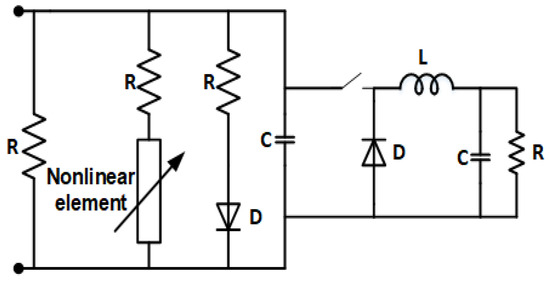
Figure 15.
Non-linear load configuration for microgrid operation.
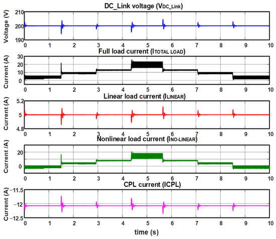
Figure 16.
Test with constant local load, constant CPL power, and variable non-linear load with PI control in the current loop and PI controller in the voltage loop.
In the DC-Link voltage signal graph, transients are observed when load changes occur, ranging from 6 V to 7 V over the reference value of 200 V; this represents a microgrid performance problem.
The linear load current signal graph (ILINEAR) has a constant value, considering that the main objective of this test is to vary the non-linear load when the non-linear load changes and transients are observed.
The CPL current signal graphs (ICPL) show that the power of renewable energy sources remained constant at 2.3 kW.
Finally, the non-linear load and the total load currents show a ripple with a value of 5 A due to the non-linear load effect. This ripple is more significant than that obtained with the linear load.
Figure 17 shows the power signals graphs associated with the CPL and battery load.
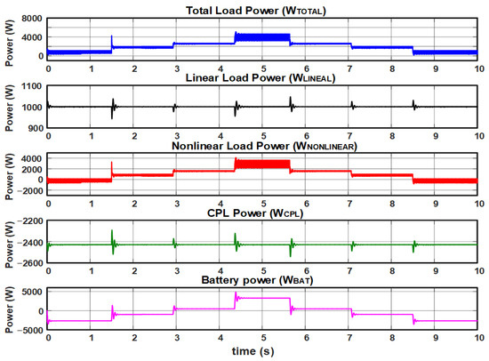
Figure 17.
Test with constant local load and constant CPL power, in addition to variable non-linear load with PI control in the current loop and PI controller in the voltage loop.
The power signal graph with linear load (WLINEAL) and power CPL (WCPL) remains constant when the load changes and the transients occur in a scale of milliseconds.
The battery power signal graph presents the expected behavior of positive and negative values related to charging and discharging. The power signal graph with non-linear load and total load shows the ripple that occurs due to the presence of the non-linear load.
5.2. Tests with PI Controller in the Current Loop and Modified PI-P in the Voltage Loop
The tests performed on the voltage loop with the Modified PI-P controller are similar to those performed with the PI controller. It will allow us to compare and validate the performance of each of these controllers in the microgrid operation.
5.2.1. Test 1
Figure 18 shows the test results in the simulation, where is plotted for different loads while the CPL power remains constant (2.4 kW). This graph shows that is maintained at a steady reference voltage value of 200 V for load current variation from 5 A to 30 A. This test highlights that with the modified PI-P controller implementation, when the load changes, the surges in the are practically zero, which contrasts with the results obtained with the PI controller implementation, where the surges have an approximate value of 5 V above and below the 200 V reference.
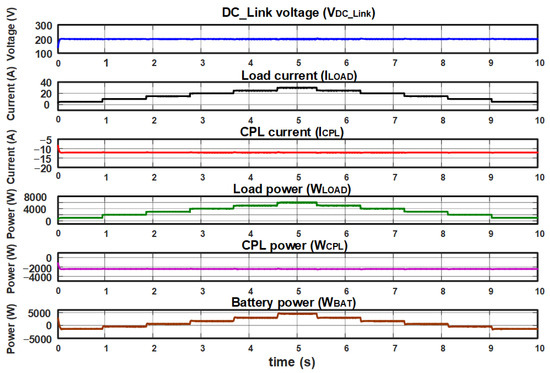
Figure 18.
Test with variable local load and constant CPL power with PI controller in the current loop and modified PI-P controller in the voltage loop.
The load current shapes (ILOAD) and load power signals (WLOAD) represent the microgrid behavior when subjected to upward and downward load changes from 0.8 kW to a value above the nominal load, 7.2 kW. In this test, the battery is discharged proportionally to the local load value variation and charged proportionally to the CPL value.
Similarly, the CPL current shapes (ICPL) and CPL power (WCPL) signals show that by keeping the DC_Link voltage constant and without overshoots, the power in the CPL also remains constant at a value of 2.3 kW without overshoot. These results represent the best performance of this controller compared with the PI controller.
5.2.2. Test 2
This test keeps the local load constant and the CPL power variable.
For this test, the load power is maintained at a constant 2 kW, while the CPL power varies from 0.8 kW to 7.2 kW. These specific CPL powers were chosen to monitor the battery’s charging and discharging behavior closely. As a result, the CPL supplies variable energy to the battery, discharging in proportion to the constant local load.
The test results are shown in the graphs of Figure 19, where now the microgrid is subjected to the previously mentioned power changes of (WCPL), while the load power (WLOAD) maintains a constant value at 2 kW. In this test, good microgrid performance is observed since even with variations in ICPL from −5 A to −30 A and WCPL, remains constant at 200 V. This test highlights that no transients occur during CPL load variations, which represents better controller performance compared to the PI controller.
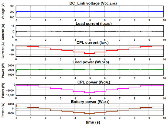
Figure 19.
Test with constant local load and variable CPL power, with PI control in the current loop and modified PI-P controller in the voltage loop.
The load current and load power signal waveforms are proportional to .
Similarly, the CPL current shapes and CPL power signals show that when power variations occur in the CPL, the CPL current presents a proportional change that varies from 0.0 A to 40 A.
5.2.3. Test 3
Figure 20 shows the microgrid voltage and current graphs with non-linear load variations.
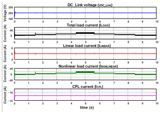
Figure 20.
The test considers linear load and constant CPL power with variable non-linear load with PI control in the current loop and modified PI-P controller in the voltage loop.
In the DC-Link voltage signal graph, no transients occur with load variations. The voltage remains constant at 200 V.
The current signal graph for a linear load presents a constant behavior, considering that the objective of this test is to vary the non-linear load, observing small transients considered negligible in the face of changes in non-linear load.
The CPL current signal plots show that the renewable energy source power remained constant at a value of 2.4 kW.
Finally, the non-linear load and total load current signals graphs show the effect of the non-linear current, which generates a ripple in the 3 A current waveform. The ripple of the current waveform is worse than that produced with the linear load. However, it is smaller than the ripple obtained with the PI controller implementation.
Figure 21 shows the waveforms of power signals associated with the CPL and battery load. This power signal graph was obtained with a linear load (ILINEAL). CPL power (WCPL) remains constant, and when the load changes, small transients occur at intervals of milliseconds. However, these are lower than those presented in the microgrid voltage loop with the PI controller.
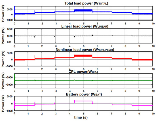
Figure 21.
Test with constant local load and constant CPL power, in addition to variable non-linear load with PI control in the current loop and modified PI-P controller in the voltage loop.
The graph battery power signal shows an expected behavior, where the positive and the negative power values are related to its charging and discharging.
The graph of non-linear load power and the total load shows the ripple effect due to the non-linear load current. However, these are lower than those presented in the microgrid voltage loop with the PI controller.
6. Analysis of Results
Table 2, Table 3, Table 4 and Table 5 present the data from the three tests carried out with a PI controller in the current loop and a PI and modified PI-P controller in the voltage loop to compare and validate its performance. Considering island mode operation, the microgrid aims to maintain the amplitude and regulation.
Table 2.
Test 1 data with variable local load and constant CPL power with PI controller in the current loop and PI and modified PI-P controller in the voltage loop.
Table 3.
Test 2 data with constant local load and variable CPL power, with PI control in the current loop and PI and modified PI-P controller in the voltage loop.
Table 4.
Test 3 data with linear local load, constant CPL power, and variable non-linear load with PI control in the current loop and PI and modified PI-P controller in the voltage loop.
Table 5.
Tests with linear local load, constant CPL power, and variable non-linear load with PI control in the current loop and PI and modified PI-P controller in the voltage loop.
Table 2 presents the data of test 1, microgrid operation with variable local load and constant CPL power with a PI controller in the current loop and PI and a modified PI-P controller in the voltage loop. It is observed that with the PI controller in the voltage loop, regulation remains constant at 200 V when the load changes and transients of 5 V above and below the reference happen. These results contrast those obtained in the modified PI-P controller since remains constant at 200 V, and no transients practically occur during load changes. This behavior represents better latter controller performance. The presence of signal transients causes variations in the power values (WLOAD), (WCPL) and (WBAT). Finally, when observing the battery power data, its charging and discharging from negative to positive power values are observed.
Table 3 presents the data test 2, microgrid operation with constant local load and variable CPL power, with PI control in the current loop and PI and modified PI-P controller in the voltage loop. Table 3 shows the same behavior presented in test 1 with a PI controller in the voltage loop. regulation remains constant at 200 V, although there are transients due to CPL variations with an amplitude of 5 V above and below the 200 V reference. This behavior improved with the modified PI-P control implementation where the transients are negligible, and regulation keeps to 200 V. Also, when signal transients occur with the PI controller, transients presented in the load power signal (WLOAD) contrast with those obtained with the modified PI-P controller. Finally, observing the battery power data, its charging and discharging, the values jump from positive to negative.
In Table 4 and Table 5, the data of test 3 are presented, with local linear load and constant CPL power, in addition to variable non-linear load with PI control in the current loop and PI and a modified PI-P controller in the voltage loop. The same behavior can be observed in tests 1 and 2; with the PI controller in the voltage loop, regulation is 200 V and transients of 5 V above and below the 200 V reference. As in tests 1 and 2, it is evident that the signal with the PI controller in the voltage loop causes transients. However, these transients do not occur with the Modified PI-P controller. Finally, observing the battery power data, its charging and discharging, the values jump from positive to negative.
Table 6 appears below, summarizing the main contributions presented in the current literature and the contribution presented in this work regarding the topic addressed in this research.
Table 6.
Contributions summary from existing works in the literature and the work developed in this research.
7. Conclusions
In this work, a DC microgrid for island mode operation was proposed to supply local loads efficiently. The proposed DC microgrid could be a solution in applications where local loads are provided by direct current. Therefore, its use can be extended to residential, commercial, service, and industrial consumption sectors. The microgrid model was developed, and the controllers for its operation were designed, particularly a PI controller designed for the current loop. Two controllers were designed for the voltage loop: PI and modified PI-P. Notably, the voltage loop controllers present a relevant task since, in this operation mode, the microgrid objective is to maintain a constant regulated to 200 V with load variations. To validate this controller performance, three microgrid operation tests were carried out and presented in the Simulations section, which allowed the table data to be obtained, as reported in the Results Analysis section. For example, in the three tests carried out, it was observed that with the PI controller in the voltage loop, the signal presents transients with an amplitude of 5 V below and above the 200 V reference, representing poor controller performance. However, with the modified PI-P controller in the three tests, remains constant at 200 V with a negligible transient amplitude of 0 V, which shows more excellent performance. Other relevant data on microgrid performance is described below.
Considering the previous data, it is evident that in the three tests carried out, the transients that occur in the signal with the PI controller cause transients in the load power signal (WLOAD), (WCPL), and (WBAT) of 50 V, results that contrast with those obtained with the Modified PI-P controller where the transients are negligible with values close to 5 V. When analyzing the battery power data for the three tests, it is noted that during charging and discharging with the PI controller in the voltage loop, greater magnitude occurs transients with values close to 800 W. Meanwhile, with the modified PI-P controller, these transients have a maximum amplitude of 100 W.
Finally, it is concluded that after analyzing the microgrid operation data for the three tests carried out, with the PI and modified PI-P controller in its voltage loop, the microgrid presents greater performance with a second controller.
Future work will develop an experimental prototype of a microgrid to be able to carry out experimental tests and implement adaptive control strategies, considering the parametric uncertainties of the microgrids.
Author Contributions
Formal analysis, H.A.S., R.O., O.C. and J.J.R.; investigation, H.A.S., R.O., O.C. and J.J.R.; methodology, R.O., L.M.O., V.H.G. and D.M. All authors have read and agreed to the published version of the manuscript.
Funding
Secretaria de Investigación y Posgrado del Instituto Politécnico Nacional (IPN), grant number 2199.
Data Availability Statement
Data are contained within the article.
Acknowledgments
Rubén Ortega thanks the Instituto Politécnico Nacional for financing his research stay at the Escuela Superior de Ingeniería Mecánica y Eléctrica, Unidad Zacatenco.
Conflicts of Interest
The authors declare no conflicts of interest.
References
- Cao, X.; Wang, J.; Zeng, B. Distributed Generation Planning Guidance Through Feasibility and Profit Analysis. IEEE Trans. Smart Grid 2018, 9, 5473–5475. [Google Scholar] [CrossRef]
- Saeed, M.H.; Fangzong, W.; Kalwar, B.A.; Iqbal, S. A Review on Microgrids’ Challenges & Perspectives. IEEE Access 2021, 9, 166502–166517. [Google Scholar]
- Che, L.; Shahidehpour, M.; Alabdulwahab, A.; Al-Turki, Y. Hierarchical Coordination of a Community Microgrid with AC and DC Microgrids. IEEE Trans. Smart Grid 2015, 6, 3042–3051. [Google Scholar] [CrossRef]
- Al-Ismail, F.S. DC Microgrid Planning, Operation, and Control: A Comprehensive Review. IEEE Access 2021, 9, 36154–36172. [Google Scholar] [CrossRef]
- Kondrath, N. Bidirectional DC-DC converter topologies and control strategies for interfacing energy storage systems in microgrids: An overview. In Proceedings of the 2017 IEEE International Conference on Smart Energy Grid Engineering (SEGE), Oshawa, ON, Canada, 14–17 August 2017. [Google Scholar]
- Nagamalli, K.R.; Tadepalli, P.S.; Pullaguram, D.R. Effect of CPL on the Stability of DC Microgrid. In Proceedings of the 2022 IEEE 2nd International Conference on Sustainable Energy and Future Electric Transportation (SeFeT), Hyderabad, India, 4–6 August 2022. [Google Scholar]
- Hamidi, S.A.; Nasiri, A. Stability analysis of a DC-DC converter for battery energy storage system feeding CPL. In Proceedings of the 2015 IEEE International Telecommunications Energy Conference (INTELEC), Osaka, Japan, 18–22 October 2015. [Google Scholar]
- Espina, E.; Llanos, J.; Burgos-Mellado, C.; Cárdenas-Dobson, R.; Martínez-Gómez, M.; Sáez, D. Distributed Control Strategies for Microgrids: An Overview. IEEE Access 2020, 8, 193412–193448. [Google Scholar] [CrossRef]
- Andalibi, M.; Hajihosseini, M.; Gheisarnejad, M.; Khooban, M.-H.; Boudjadar, J. A Novel Method for Stabilizing Buck-Boost Converters with CPL using Model Prediction Control. In Proceedings of the 2021 22nd IEEE International Conference on Industrial Technology (ICIT), Valencia, Spain, 10–12 March 2021. [Google Scholar]
- Lucas-Marcillo, K.E.; Plaza, D.A.; Barra, W.; Paiva, R.L.; Melo, E.; Vaca-Benavides, D.A.; Ríos, S.J.; Herrera, E.V. Novel Robust Methodology for Controller Design Aiming to Ensure DC Microgrid Stability Under CPL Power Variation. IEEE Access 2019, 7, 64206–64222. [Google Scholar] [CrossRef]
- Xu, Q.; Vafamand, N.; Chen, L.; Dragičević, T.; Xie, L.; Blaabjerg, F. Review on Advanced Control Technologies for Bidirectional DC/DC Converters in DC Microgrids. IEEE J. Emerg. Sel. Top. Power Electron. 2021, 9, 1205–1221. [Google Scholar] [CrossRef]
- Li, Y.; Vannorsdel, K.R.; Zirger, A.J.; Norris, M.; Maksimovic, D. Current Mode Control for Boost Converters with Constant Power Loads. IEEE Trans. Circuits Syst. 2012, 59, 198–206. [Google Scholar] [CrossRef]
- Li, X.; Jiang, W.; Wang, J.; Wang, P.; Wu, X. An Autonomous Control Scheme of Global Smooth Transitions for Bidirectional DC-DC Converter in DC Microgrid. IEEE Trans. Energy Convers. 2021, 36, 950–960. [Google Scholar] [CrossRef]
- Kwon, M.; Choi, S. Control Scheme for Autonomous and Smooth Mode Switching of Bidirectional DC–DC Converters in a DC Microgrid. IEEE Trans. Power Electron. 2018, 33, 7094–7104. [Google Scholar] [CrossRef]
- Sidorov, V.; Chub, A.; Vinnikov, D.; Lindvest, A. Novel Universal Power Electronic Interface for Integration of PV Modules and Battery Energy Storages in Residential DC Microgrids. IEEE Access 2023, 11, 30845–30858. [Google Scholar] [CrossRef]
- Pires, V.F.; Cordeiro, A.; Roncero-Clemente, C.; Rivera, S.; Dragičević, T. DC–DC Converters for Bipolar Microgrid Voltage Balancing: A Comprehensive Review of Architectures and Topologies. IEEE J. Emerg. Sel. Top. Power Electron. 2023, 11, 981–998. [Google Scholar] [CrossRef]
- Chen, D.; Xu, L.; Yao, L. DC Voltage Variation Based Autonomous Control of DC Microgrids. IEEE Trans. Power Deliv. 2013, 28, 637–648. [Google Scholar] [CrossRef]
- Pannala, S.; Patari, N.; Srivastava, A.K.; Padhy, N.P. Effective Control and Management Scheme for Isolated and Grid Connected DC Microgrid. IEEE Trans. Ind. Appl. 2020, 56, 6767–6780. [Google Scholar] [CrossRef]
- Mohammadi, F.; Mohammadi-Ivatloo, B.; Gharehpetian, G.B.; Ali, M.H.; Wei, W.; Erdinç, O.; Shirkhani, M. Robust Control Strategies for Microgrids: A Review. IEEE Syst. J. 2022, 16, 2401–2412. [Google Scholar] [CrossRef]
- IEEE Std 2030.10-2021; IEEE Standard for DC Microgrids for Rural and Remote Electricity Access Applications. IEEE: New York, NY, USA, 2020; pp. 1–47.
- Al-Obaidi, N.A.; Abbas, R.A.; Khazaal, H.F. A Review of Non-Isolated Bidirectional DC-DC Converters for Hybrid Energy Storage System. In Proceedings of the 2022 5th International Conference on Engineering Technology and Its Applications (IICETA), Al-Najaf, Iraq, 31 May–1 June 2022. [Google Scholar]
- Farsizadeh, H.; Gheisarnejad, M.; Mosayebi, M.; Rafiei, M.; Khooban, H.M. An Intelligent and Fast Controller for DC/DC Converter Feeding CPL in a DC Microgrid. IEEE Trans. Circuits Syst. 2020, 67, 1104–1108. [Google Scholar] [CrossRef]
- Liu, X.; Zhao, T.; Deng, H.; Wang, P.; Liu, J.; Blaabjerg, F. Microgrid Energy Management with Energy Storage Systems: A Review. CSEE J. Power Energy Syst. 2023, 9, 483–504. [Google Scholar]
- Cho, K.M.; Oh, W.S.; Kim, Y.T.; Kim, H.J. A New Switching Strategy for Pulse Width Modulation (PWM) Power Converters. IEEE Trans. Ind. Electron. 2007, 54, 330–337. [Google Scholar] [CrossRef]
- Liao, Y.; Wang, X. Small-Signal Modeling of AC Power Electronic Systems: Critical Review and Unified Modeling. IEEE Open J. Power Electron. 2021, 2, 424–439. [Google Scholar] [CrossRef]
- Mohan, N.; Undeland, T.; Robbins, W. Power Electronics: Converters, Applications, and Design, 3rd ed.; John Wiley & Sons: Hoboken, NJ, USA, 2002. [Google Scholar]
- He, S.; Hung, J.Y.; Nelms, R.M. Small-Signal Modeling of I2 Average Current Mode Control. IEEE Trans. Power Electron. 2016, 31, 3849–3858. [Google Scholar] [CrossRef]
- Ogata, K. Modern Control Engineering, 4th ed.; Prentice Hall: Upper Saddle River, NJ, USA, 2002. [Google Scholar]
- Benavent, J.M.; Figueres, E.; Garcera, G.; Pascual, M. Robust model-following regulator for average current-mode control of boost DC-DC converters. In Proceedings of the ISIE 2005 IEEE International Symposium on Industrial Electronics, Dubrovnik, Croatia, 20–23 June 2005. [Google Scholar]
- PSIM 11.1 User’s Guide; Powersim: Rockville, MD, USA, 2018.
Disclaimer/Publisher’s Note: The statements, opinions and data contained in all publications are solely those of the individual author(s) and contributor(s) and not of MDPI and/or the editor(s). MDPI and/or the editor(s) disclaim responsibility for any injury to people or property resulting from any ideas, methods, instructions or products referred to in the content. |
© 2024 by the authors. Licensee MDPI, Basel, Switzerland. This article is an open access article distributed under the terms and conditions of the Creative Commons Attribution (CC BY) license (https://creativecommons.org/licenses/by/4.0/).