Abstract
In this paper, a control strategy of a cell-based multi-agent system is proposed to solve the problem of inconsistency of series lithium-ion battery packs. The bidirectional Cuk converter is utilized as an equalizing circuit serving for balancing adjacent cells in a pack. A SOC-based consensus control with a time-triggered mechanism (TTM) is proposed. In order to reduce the actuator updates, the control method is ameliorated by altering TTM to an event-triggered mechanism (ETM). Adjustable balancing currents are designed in both TTM and ETM methods for the acceleration of the equalization process. The cases in dynamic environments under externally imposed charging/discharging currents by adopting TTM and ETM methods are investigated in detail. By comparison, the simulations and hardware-in-the-loop (HIL) experiments with a Typhoon real-time simulator are illustrated to show that, both in standby or external charging/discharging conditions, the proposed ETM algorithms are superior to TTM’s in terms of equalization time and adaptability to the external environment.
1. Introduction
To solve the problems of energy crisis, sustainable energy has been developed and received extensive attention. As an important player in sustainable energy, lithium-ion batteries have been widely used in many fields, such as electric vehicles [1,2] and battery energy storage systems [3,4], due to their merits including high energy density, low self-discharge rate, low cost and rechargeable operation. Considering the low-voltage and low-power features of the battery cell [5], it is necessary to connect multiple cells in series and parallel to increase the capacity of the pack for high-voltage and high-power applications. However, there exists a difference in production process, temperature and others, and the same type of batteries that are produced by the same manufacturer show inconsistency during use [6]. To address this phenomenon, the SOC difference [7] of cells in a pack is presented to describe the inconsistency of the battery pack [8]. The cell with the highest or lowest SOC states plays a decisive role and affects the charging and discharging performance, which changes the loss distribution and the long-term service life of the pack [9]. In other words, the service life is usually limited by the shortest-life cell, and this phenomenon is called the “barrel effect”.
Although the problem of eliminating the inconsistency of battery packs is a big challenge [10,11,12], advancements have been made regarding the inconsistency mechanism and advanced strategy. By balancing the SOC levels of all cells, the service life and safety performance of the pack need to be improved. In this case, the battery-balancing problem can be equivalently solved by the minimization of the cell SOC difference. The battery balancing methods can be categorized into two types: the passive and the active methods. The former is also called dissipation equalization and achieves pack balancing by means of energy-consuming components such as switch resistors, which is only applicable in the charging phase. The latter is also called the non-dissipative equalization method, which achieves SOC consistency across the battery pack by shifting energy from higher cells to lower cells through equalization circuits [13]. Compared with the passive method, it attracts more attention, which is attributed to its lower amount of energy used for dissipation and faster equalizing speed. Active balancing methods are transformed into the following forms: cell-to-cell, cell-to-pack, pack-to-cell, and pack-to-pack [11].
Compared with other balancing topologies, the cell-to-cell balancing structure potentially achieves better efficiency [14]. This method realizes the equalization of all cells in a pack by installing an ICE among the cells. The ICE has the merits of quick equalization, simple implementation, and low cost. From the perspective of equalization topology, innovative structures such as layered equalization have been developed in the acceleration of equalization speed [15], but this increases the number of ICEs and the complexity of the topology. Many balancing methods have been proposed, such as the multi-agent consensus control based on multi-objective constraints [16]. However, it fails to output a reasonable current to suppress the inconsistency during the charging process. In addition, precise balancing requires additional cost, complexity, and strict cooling design. A quasi-sliding mode control strategy with SOC estimation [17] and an equalization strategy based on predictive control [18] are proposed. But these types of methods can easily become computationally infeasible and impractical. Some methods have been applied to optimize the battery balancing system, such as genetic algorithm, neural network [19], and particle swarm [20]. Moreover, the distributed consensus strategies of battery balancing are growing hot spots and are widely used in factory electronics. Following the consensus spirit, the controlled system converges to a balancing state with high speed and time-saving properties. The “plug and play” function can be realized even when facing an abnormal emergency due to its strong robustness and fast self-solving under the conditions of system faults, showing the system’s flexibility and resiliency. Based on the intelligent reconfigurable battery, a multi-agent voltage balancing strategy is applied [21], but it requires memory for each battery node and becomes costly. In this sense, the consensus control for battery balancing is proposed in this paper to explore the memory-less scheme, so that the memory for each cell is not required anymore.
Inspired by the study of the distributed consensus method in the secondary control of the DC microgrid [22], an event-triggered consistency control strategy [23] with a communication-less design is proposed to solve the problem of SOC balance and power allocation among the distributed energy storages. However, the consensus will not spread to the cell level, which has long-term negative impacts on lithium-ion battery safety. To solve the cell-based inconsistency problem, a novel TTM and ETM balancing strategy with a centralized structure is proposed in this paper.
The contributions in this paper are as follows: the balancing system is built as a multi-agent system, where each battery cell is regarded as an agent and multi-agent control is adopted during the balancing process. In addition, an event-triggered mechanism is added in multi-agent system control, which is greatly beneficial to reducing the balancing convergence time and the update frequency of the actuator. To accelerate the balancing speed, the method of adjusting equalizing current is proposed for achieving cell consensus. The equalizing current becomes time-variable with the sampled data instead of a stable current. An improved balancing converter based on bidirectional Cuk [17] is utilized for bidirectional energy transfer among cells with different SOCs. The process is implemented via PWM applying to MOSFET of the ICE to generate a time-varying equalizing current. An equalization strategy based on multi-agent consensus control with sampled data featuring ETM is proposed in this paper.
The remainder of this paper is organized as follows: In Section 2, a model of the balancing system for a series-connected battery pack is presented. In Section 3, a TTM algorithm for balancing the battery pack by adjusting the balancing current is proposed. In Section 4, an equalization strategy based on ETM towards sampled data is proposed to speed up the equalization speed and reduce the actuator updates. Simulation results are presented in Section 5. HIL experiments are described in Section 6. This paper is concluded in Section 7.
2. Equalizing System for Cells
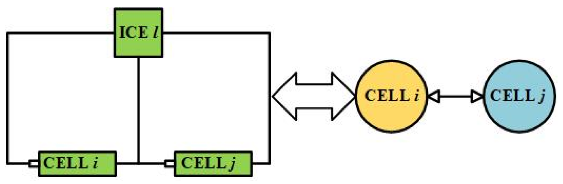
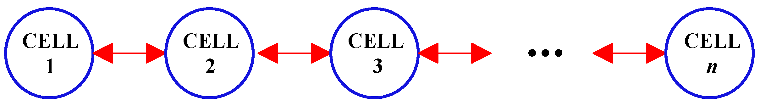
In general, a series-connected battery pack has n cells and n − 1 ICEs with bidirectional Cuk. The balancing system is designed as a multi-agent system with a fixed topology of G, where the battery cell is taken as a node and the ICE is an edge, as shown in Figure 1.
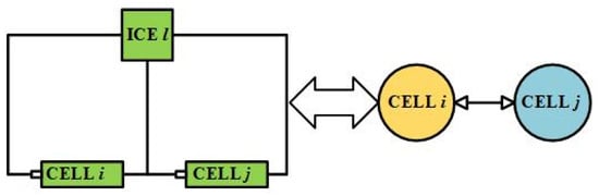
Figure 1.
The structure of cells and connected ICE.
2.1. The Model of ICE
In Figure 1, ICE is oriented as an edge to connect nodes of battery i, j. In other words, ICE is the interface of bidirectional energy transfer for batteries i and j.
The left part of Figure 1 shows the circuit structure composed of ICE and batteries i, j. The right part is an equivalent topology that batteries i and j are connected to as nodes through an edge with a bidirectional energy-transferring channel; it is equivalent to a fully directed graph. In this paper, an improved bidirectional Cuk converter is used as the cell equalizer, and its circuit model is shown in Figure 2.

Figure 2.
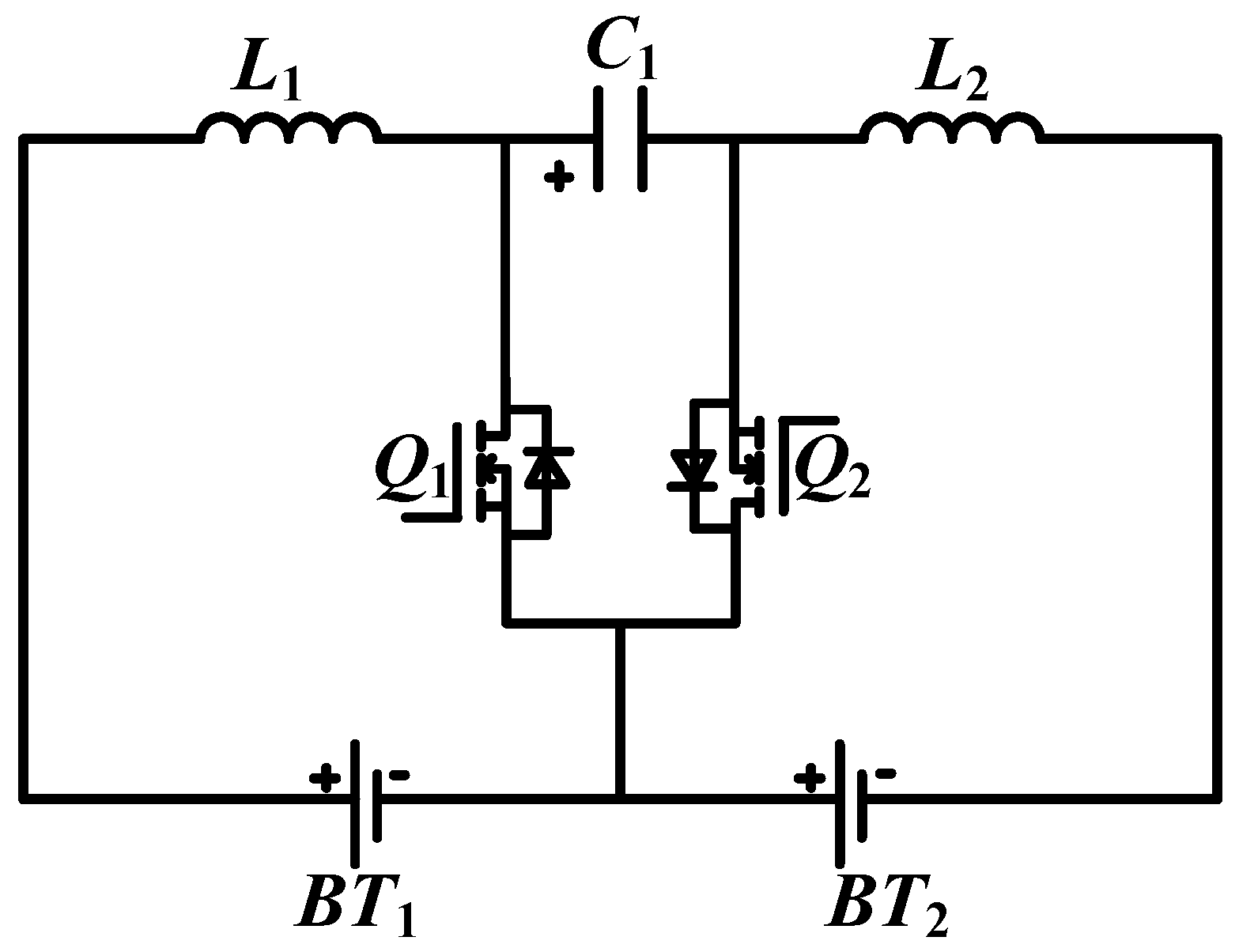
Cell equalizer with bidirectional Cuk topology.
The battery equalizer is composed of two MOSFETs Q1 and Q2, two uncoupled inductors L1, L2 and an energy storage capacitor C1. Because the bidirectional ICE possesses a symmetrical structure, which can realize the bidirectional transfer of energy between the two adjacency cells. The circuit is equipped with an alterable direction of balancing current by controlling Q1 and Q2. The magnitude of the balancing current is adjusted by the duty cycle of the PWM signal. The circuit component models in the bidirectional Cuk are defined in Table 1.

Table 1.
Specifications of ICE converter.
When battery i needs to be discharged for battery j, the duty cycle of MOSFET Q1 is for the regulation of equalization current; meanwhile, the duty cycle of Q2 is constantly zero, so that the energy transmission from cell i to cell j is realized. Conversely, energy transferring from battery j to battery i can be achieved in the same manner.
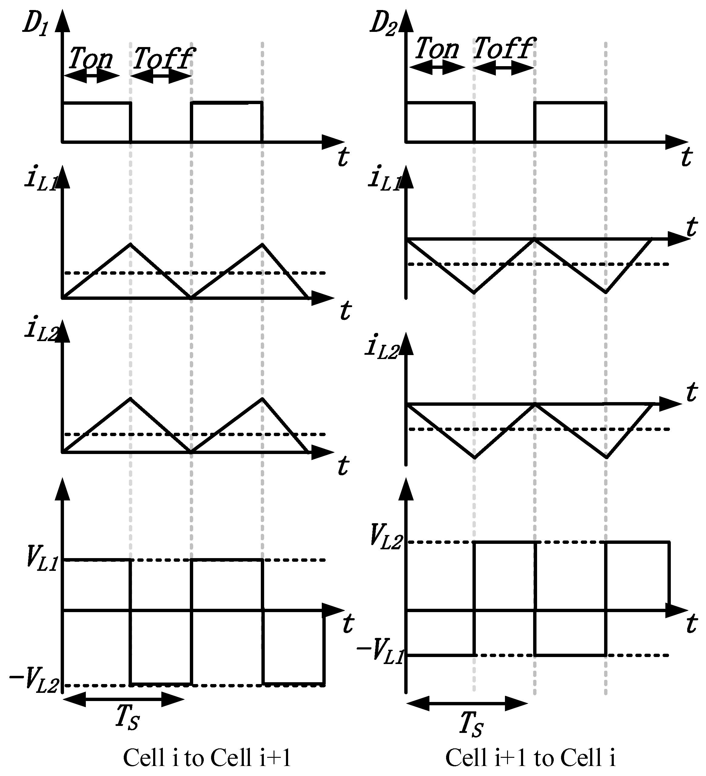
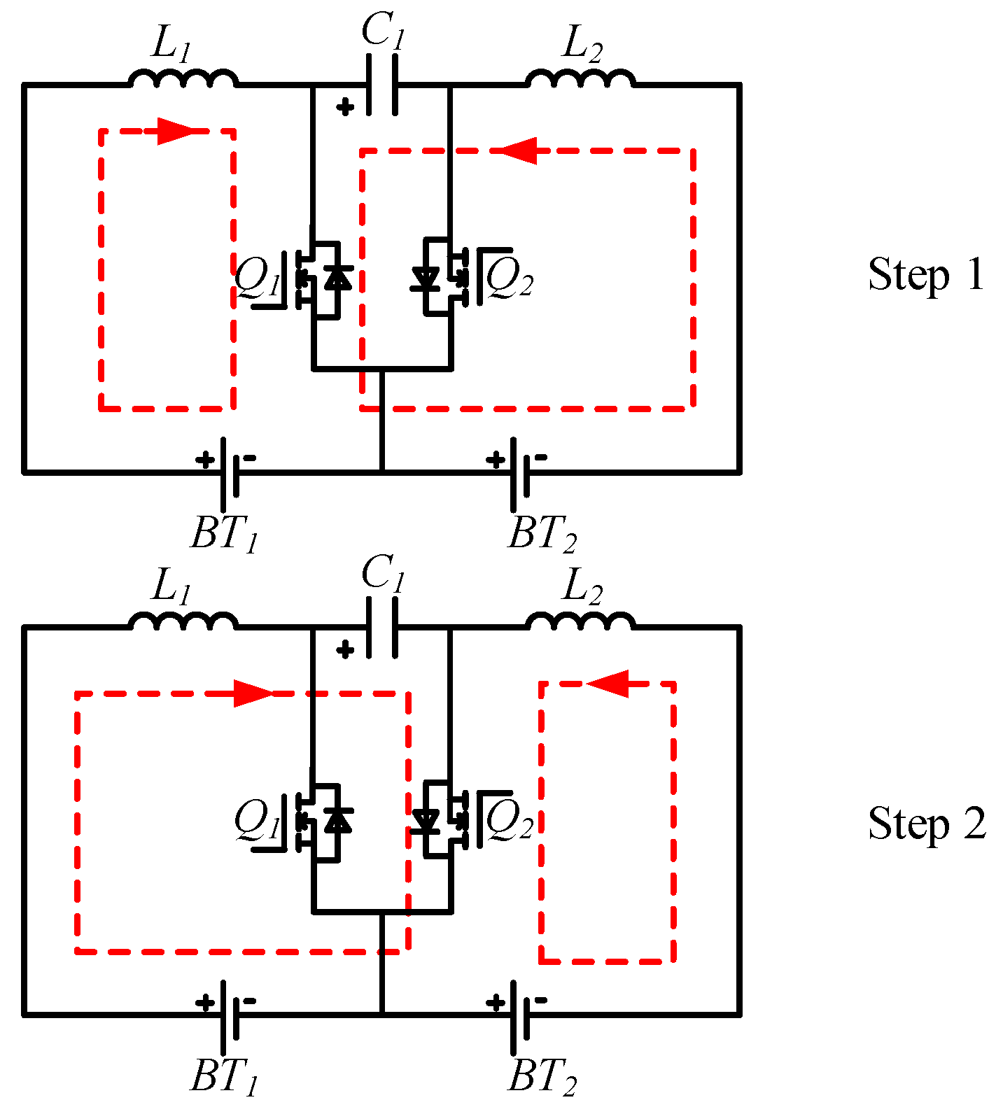
As shown in Figure 3, when MOSFET Q1 is turned on, L1 and L2 absorb energy from cell i and capacity C1, respectively. The voltage of L1 is stable and it is kept charging. And L2 storages energy from C1, which is the energy flow exhibited in step 1. While MOSFET Q1 is turned off, L1 transfers energy to C1 and L2 transfers energy to cell i + 1, which accords to step 2 in Figure 4. Accordingly, the energy transfer from cell i to cell i + 1 is realized.
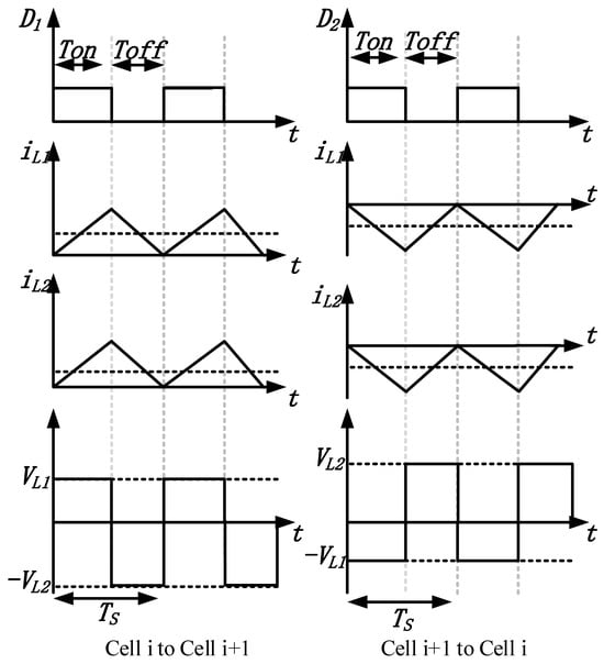
Figure 3.
The waveform of inductive current voltage and duty cycle in bidirectional Cuk equalization circuit.
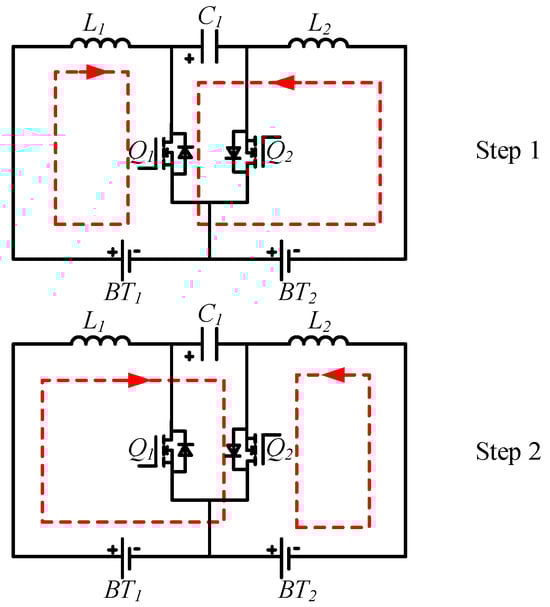
Figure 4.
The operation steps for equalizing the two cells via ICE.
In addition, the balancing current is computed and defined by the average value derived from the measured inductor current of ICE. The average inductor current is defined as follows when cell i is connected to cell i + 1 and discharges to cell i + 1:
where and are the average current of and , respectively, is the average voltage of the capacitor , denotes the voltage of the ith cell, and represents the equalizing current through ICE. is switching period and represents the PWM duty cycle which is applied to the MOSFET on the discharge side. Similarly, when the i + 1th cell discharges its energy to the ith cell, the average balancing current can be written as follows:
where is the voltage of the i + 1th cell, and is the duty cycle applied to the MOSFET on the discharge side.
In the lth bidirectional converter, MOSFETs and are turned on and off complementarily. According to Formulas (1) and (2), the duty cycle corresponding to the controlled balancing current can be obtained as follows:
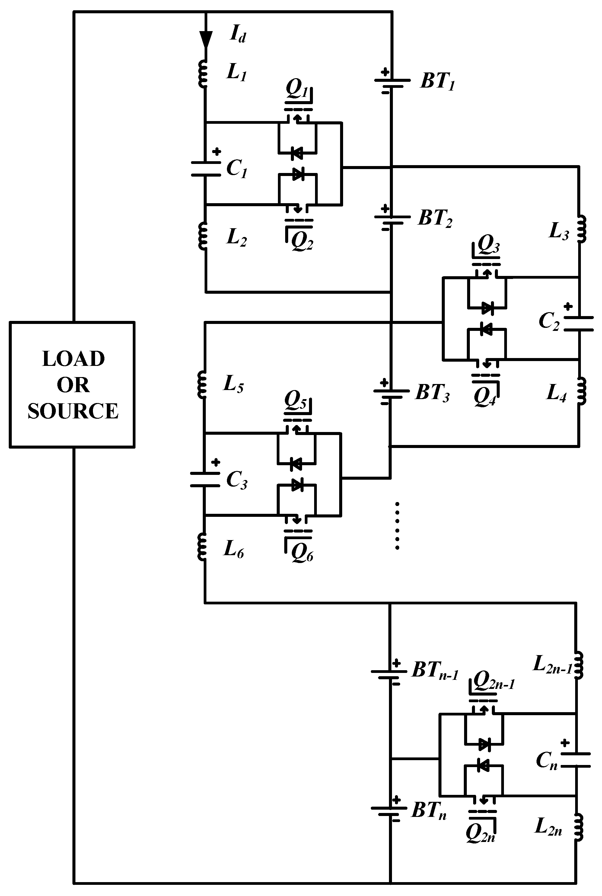
The direction of the balancing current flowing from the ith to the (i + 1)th cell via ICE l is defined as a positive direction, which has been addressed by in Figure 5.

Figure 5.
A serial-connected battery pack with bidirectional Cuk equalizers.
By measuring the average voltage of the battery and capacitor, the duty cycle of MOSFET at each sampling time can be obtained after the appropriate design of balancing current. In Section 3, a consensus algorithm for adjusting the balancing current is proposed, and the corresponding duty cycle can be obtained by using and calculating Formulas (3) and (4).
2.2. Balancing Current Design
The balancing current between cell i and cell j passing through ICE l can be uniformly expressed as follows:
where and are the balancing current of cell i and cell j flowing into ICE l, respectively, and are the equalizing current of cell i and cell j, respectively, and is the energy transfer efficiency of ICE l satisfying . But in ICE l, the energy transfers can only be non-bidirectional. When the current is positive, there is ; otherwise,. The current passing through ICE l to cell j is simplified as follows:
is used to simplify the balancing current through ICE. According to Formulas (5)–(8), it can be further deduced as:
For the convenience of analysis, the energy transfer efficiency is assumed as .
2.3. Model of Cell Balancing System
Assume that the initial SOC of each cell at the initial time is known, the SOC can be calculated by using the Coulomb counting method as follows:
where and represent the SOC state of cell i at time t and t0, respectively.
The state equation of the cell’s SOC is computed by:
The sampling period is defined as , and Equation (11) is discretized to obtain:
where represents the SOC of cell i, and , is the Ampere-hour energy of cell i and is the Coulomb efficiency with for discharging and for charging.
For a series-connected cell pack with cells and ICEs, the terminal current of a cell is calculated by:
For , is negative, occurring at discharging operation for the ith cell and vice versa. is the current crossing the whole cells while the pack discharges to an external load or charges from the power source; each cell in a pack has the same external current . is the equalizing parameter and is defined as:
According to Equations (13) and (14), the balancing model in the charging/discharging pattern for a series-connected pack can be expressed as:
is the external current of the whole pack, the same as mentioned before. In the actual working process, there are certain constraints on the current and cell SOC.
2.4. Constrains of the System
2.4.1. Equalizing Current Constraints
The equalizing current is very important to the safety of the battery cell. The current should be kept within a reasonable range to prevent harmful overcharging and over-discharging. The constraint of is defined as:
indicates the maximum allowable current during the equalization process. According to Formula (17), it can be found that the controlled equalizing current satisfies the following constraints:
It is observed that the upper bound of the equalizing current is time-varying, which changes with the external charging or discharging current.
2.4.2. Cell SOC Constraints
The cell’s SOC should be restrained in normal operation to avoid overcharging or over-discharging and its constraint is expressed by:
where and represent the upper bound and lower bound of the SOC, respectively.
3. Equalizing System for Cells
Since battery SOC estimation has been deeply investigated and developed [24,25,26], the battery SOC at each sampling instant is supposed to be known. In this section, the relationship between battery cells and ICE is investigated through graph theory in detail.
3.1. Graph Theory
The network topology of the multi-agent system can be modeled as an undirected graph . The edge represented by the ordered pair indicates that agent i and agent j have neighborhood interactions, which is expressed by . In a series-connected pack, each cell is regarded as a node, and an edge is built by the path connecting two cells through ICE. is represented as the point set of cells and is the set of interconnected edges. The balancing path covers all edges, which is denoted as , . The set of neighbors of battery cell i is expressed by . The graph G is called to be connected if there exists a connecting path between any two cell nodes in graph G. As shown in Figure 6, the balancing topology of a battery pack can be equivalent to a fully directed graph, where each pair of different cells is bidirectionally connected via an edge. Two matrices are used to represent the balancing topology, one is the adjacency matrix . If , then and otherwise . The other is the degree matrix , where represents the sum of battery cells in set Ni, the number of other cells connected with the ith node. The Laplacian matrix is defined as and , , . For general directed graphs, the Laplacian matrix is usually asymmetric. Therefore, the cell balancing topology in this paper is a fully directed graph, and the Laplacian matrix is symmetric, so . The eigenvalues of L are all real numbers and can be addressed by , where , is the smallest non-zero eigenvalue and represents the algebraic connectivity of the equalizing topology. In addition, the value of has a certain influence on the equilibrium speed of the system.
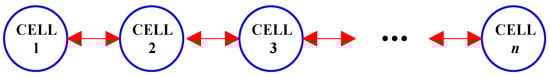
Figure 6.
Topology graph of the cell equalizing system.
According to the cell equalizing topology in Figure 6, the Laplacian matrix L is presented as follows:
Remark 1.
Assuming the fully directed graph of the balancing system is fully connected in this paper.
3.2. Multi-Agentconsensus Control
For a multi-agent system, the dynamics of each agent with a single integrator is defined as follows:
where is the state and can be redefined as the SOC of cell i, and represents the control input of agent i. The consensus control input is designed by:
where is the control gain between agent i and j over the time scale t. The main idea is to move the state of each agent towards its neighbors’ state to finally achieve consensus. For a connected graph, all agents under the dynamic (20) and control law (21), will eventually converge to consensus. In practice, the network topology model may be changed with the dynamic trajectory of the pattern, which leads to the change in neighbor agents. A multi-agent system can also achieve consensus if the underlying graph has a directed spanning tree in a joint-connected manner in terms of the union of its time-varying graph topologies.
Remark 2.
Considering the balancing topology changes over different time scales are neglected, the topology is supposed to be in stable operation at each moment.
Theorem 1.
Given for , if succeeds, the consensus of dynamics (20) will be asymptotically realized.
The balancing structure of the system is outlined in Figure 7. As shown, the collector of the battery state activates the collection for each cell at the sampling instant, and then the collected states are submitted to the consensus controller. The control law is reset by the consensus controller at each sampling instant, and the updated control law of each cell is given to the connected ICE through the drive circuit.
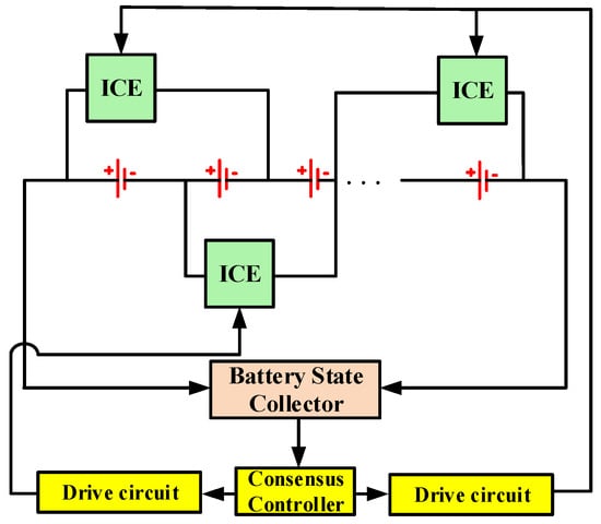
Figure 7.
The balancing structure of the whole system.
Define , and SOC state model of the cell under consensus control can be obtained as follows:
where the consensus controller is written as:
The equalizing current will be reset with the change in . Combining Formulas (23) and (24), it can be further obtained as follows:
Combining the Laplacian matrix (20) and (25), the compact form of (25) can be rewritten as follows:
where represents the external current during charging or discharging or under external dynamic current conditions and .
Because this equalizing strategy updates its actuator based on the latest sampled data, this pattern is featured as the time-triggered and named time-triggered method (TTM). The proof of consensus convergence of TTM can be found in Appendix A.
4. Consensus Algorithm with Event-Triggered Mechanism
Since TTM brings frequent updates to the actuator, it is necessary to find a new method driven by less-updates with sampled data, and then ETM is proposed in this paper. This strategy can not only greatly reduce the update frequency and control load, but also effectively accelerate the equalizing speed.
4.1. Battery Balancing under ETM
The measurement error of the kth sampling data is expressed by:
The sampled data of all cells in a pack is applied to update the actuator depending on the ETC rather than the fixed-time update in TTM.
The ETC of the control system can be shown as follows:
Denote the kth trigger the update time of all cells at , and the next trigger time can be defined as follows:
where h is the sampling period and represents the constant parameter greater than zero. As for , the design process is detailed in Appendix B. is the data obtained by measuring and estimating the SOC of cell i at kth time, wherein,. The set of event-triggering time is a subset of sampling-time data. The direction and magnitude of the equalizing current will only be updated when ETC is met, instead of every sampling instant. The event-triggered controller is designed based on the state and error of all cells. When the trigger condition is satisfied and the state error reaches a threshold value, the control inputs of all cells will be updated.
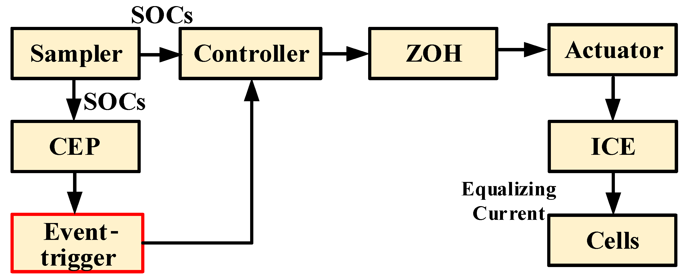
The balancing model of ETM is illustrated in Figure 8. The sampler collects SOC data of the cell at each sampling instant, and the consensus controller and the CEP receive the data from the sampler. The event detection is sensed in CEP and the signal is sent to the event trigger and controller. If the arrived signal from the event trigger is positive, the control law will be changed with the newest sampled data. And the updated controlled equalizing current will be given to cells with ICE.

Figure 8.
The balancing model of ETM.
If the ETC in Equation (28) is satisfied, the accumulated sampling-data error is still within the allowable range, and the inundated data are adopted by all actuators. The ETC is only periodically calculated and checked at each sampling instant, which greatly reduces the computational and measuring burden compared with other ETM using continuous data. In other words, the ETC in Equation (28) brings the advantages of simplifying the control procedure and saving computing resources. In conclusion, the sampler is time-driven whereas the controller and actuator are event-triggered.
4.2. ETM Consensus Protocol for Cell Balancing
It can be seen from Formula (28) that the ETC of all cells is related to their sampled data and error at the kth sampling instant. In other words, the central controller collects each cell’s SoC at the sampling instant, and the state is driven at the latest trigger time. The state error is calculated for evaluating ETC to decide whether to update the control input of all cells. Thus, a novel consensus protocol based on the sampling data is proposed as follows:
The event-triggered time interval with is divided into plenty of sampling intervals. Therefore, the consensus control protocol is derived as follows:
Formula (31) can be rewritten into a compact form by:
where and . and are the recorded SOC of batteries i and j. When the ETC is reached and Laplacian matrix L for the designed equalizing topology is derived, the SOC-based consensus model with ETM over is presented as follows:
The “back-to-origin” state convergence for most existing consensus algorithms is generally verified by the Lyapunov function design. But in this paper, the LaSalle invariance theorem is proposed to analyze the convergence of event-triggered protocols, which makes it converge to the subspace instead of the origin.
The proposed ETM balancing strategy has some outstanding advantages such as the slow updating frequency of the equalizer actuator attributed to the event-triggered sampling, which had never been reported in a battery balancing system previously. The central controller is designed to decide the update time of the actuator according to the latest sampling data derived from the ETC. It is concluded that this strategy can effectively reduce the updated number of actuators. Overall, the ETM control strategy consumes less equalization time than TTM’s, and the speed of cell equalizing is remarkably improved.
The proof of consensus convergence of ETM can refer to Appendix B.
In order to avoid the Zeno effect in the event-triggered equilibrium, the ETC is judged based on the periodic sampling data. The lower bound of the event piece time is at least the sampling period h, so the Zeno effect is naturally eliminated in the proposed ETM.
5. Simulation Results
The test of a series-connected pack with four battery cells is simulated in MATLAB. Under the traditional chain-topology pack, the TTM and ETM consensus controls are verified in standby mode and the charging/discharging mode. A series of comparisons were made for the equalizing strategy of TTM and ETM. The sampling period h equals 0.2 s. In order to validate the effectiveness of the proposed methods for convenience, the capacity of each cell is designed to be about 0.1 Ah, and the voltage of each cell is set to 3.6 V. Also, two groups of batteries with different initial values of SOC are designed, and the initial SOCs are specified as Case 1 and Case 2 in Table 2.
Table 2.
The initial SOC of cells in pack for two methods.
It can be characterized that the arrival of convergence state for the battery pack is obtained when the SOC difference in all cells and the average satisfies , where is greater than zero and represents the average SOC at each sampling instant. In practice, is designed to avoid over-equalization after the battery pack has already reached convergence.
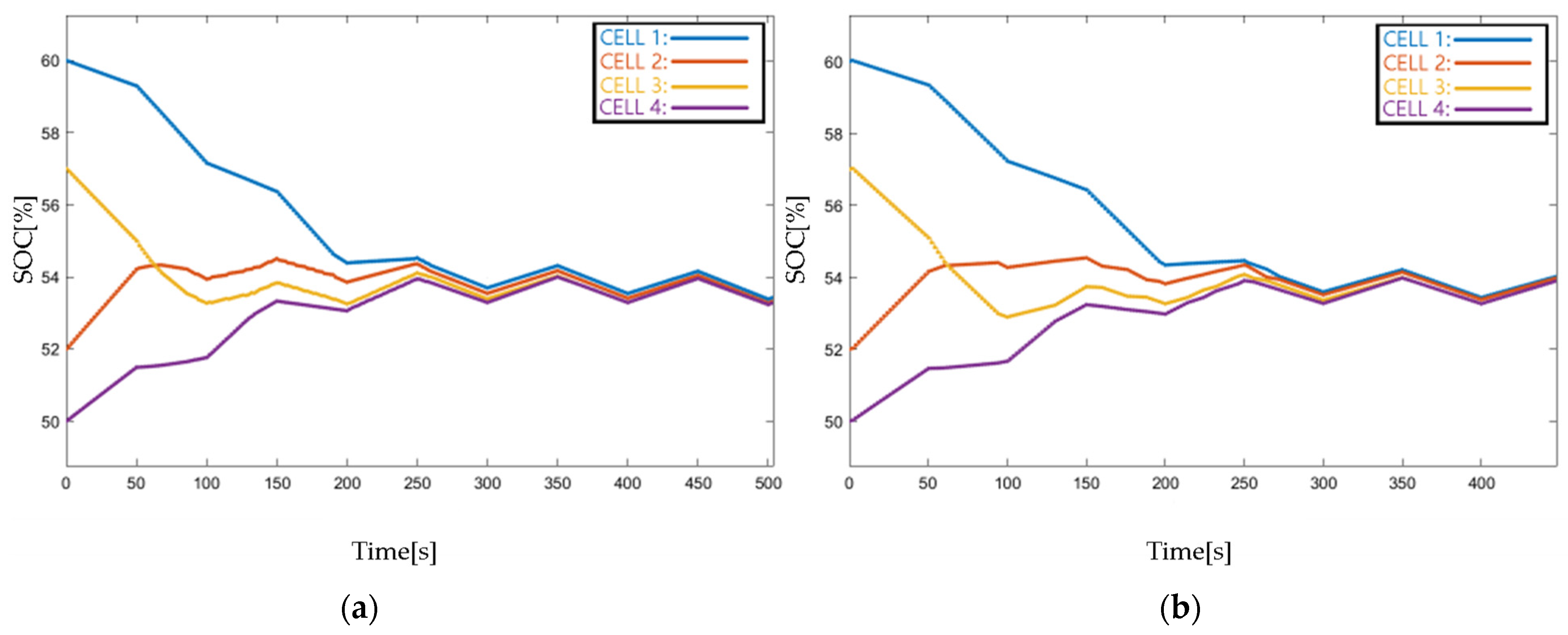
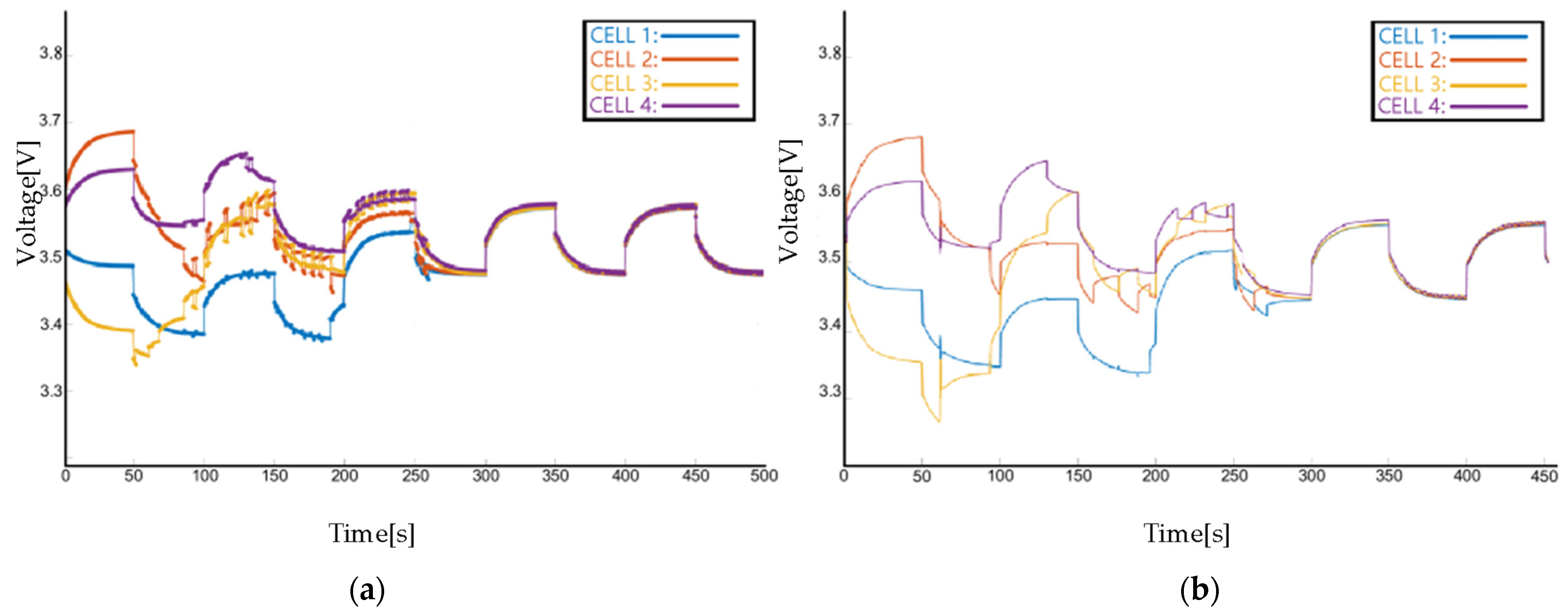
In order to verify the equilibrium state of the system under dynamic external current, the external current is imposed as 0.05 A, the period of the external current is set as 100 s, the duty cycle is 0.5, and the SOC changes in the equalizing process of TTM and ETM are shown in Figure 9. As observed, the equalizing system under external dynamic current can also converge to consensus. The TTM system converges at 504 s, the ETM system convergences at 450 s, and the equalizing speed has been accelerated by 54 s; it is about 12% faster than TTM. The result validates the effectiveness of ETM under an external variable current.
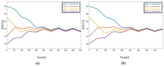
Figure 9.
SOC responses of TTM and ETM under external variable current conditions: (a) TTM, (b) ETM.
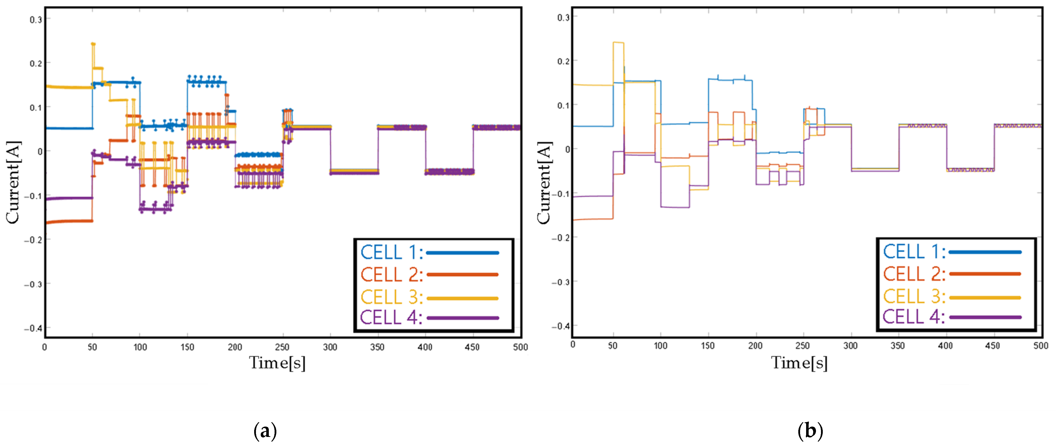
From Figure 10, Figure 11, Figure 12, Figure 13 and Figure 14, it can be concluded that the current and voltage of each cell will reach zero, and the voltage of each cell convergences to a consensus value. The ETM system has a faster convergence time.
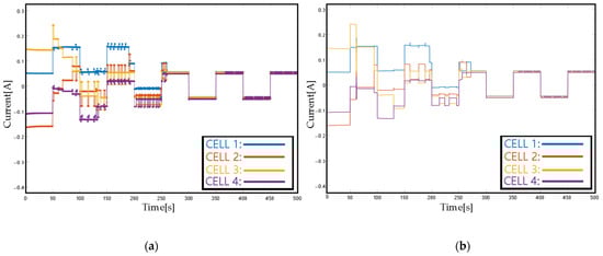
Figure 10.
Current dynamics of TTM and ETM under external variable current condition: (a) TTM (b) ETM.
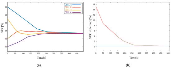
Figure 11.
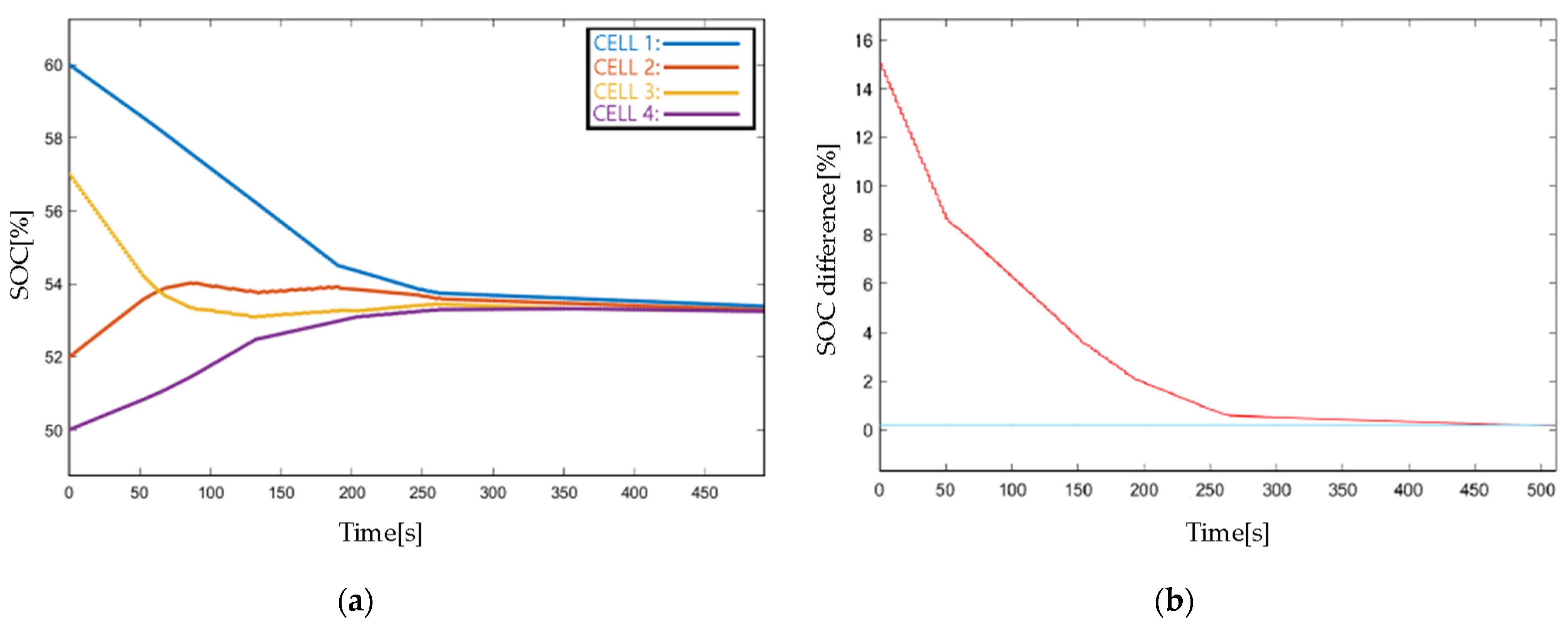
Simulation results with the coefficient of Case 1 by using TTM: (a) SOC responses in standby mode, (b) SOC difference in standby mode.
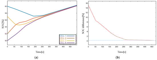
Figure 12.
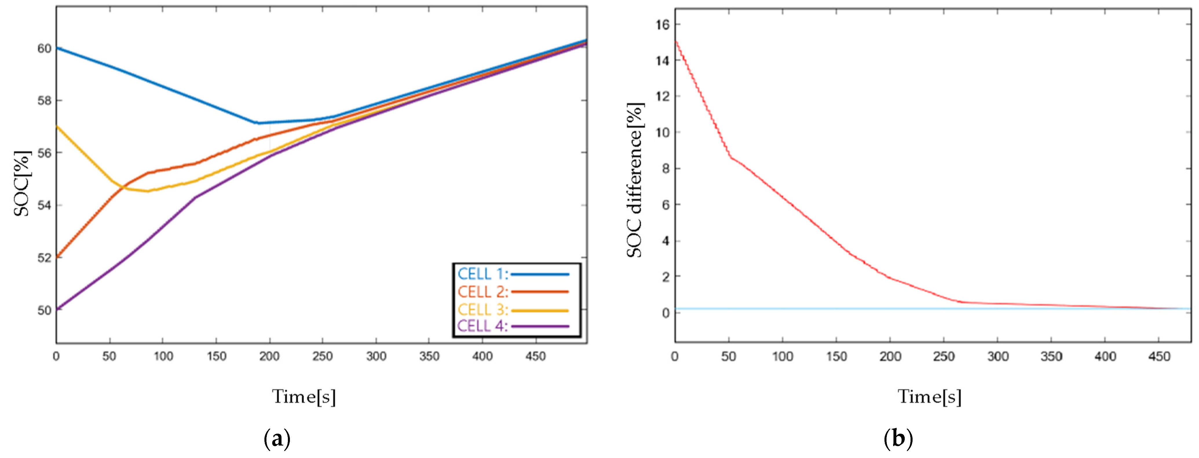
Simulation results with the coefficient of Case 1 by using TTM: (a) SOC responses in charging mode, (b) SOC difference in charging mode.
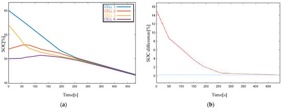
Figure 13.
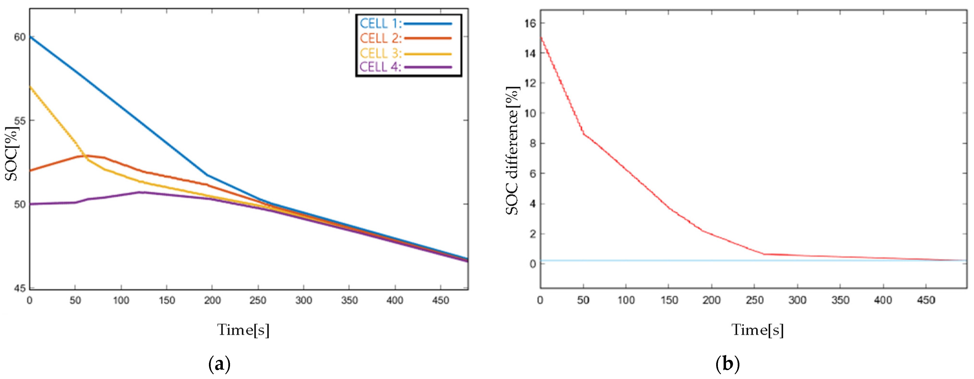
Simulation results with the coefficient of Case 1 by using TTM: (a) SOC responses in discharging mode, (b) SOC difference in discharging mode.
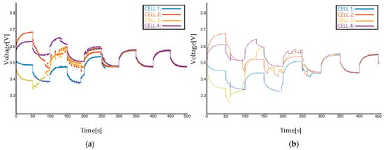
Figure 14.
Voltage dynamics of TTM and ETM under external variable current conditions: (a) TTM, (b) ETM.
The simulation results with TTM are presented in Figure 11, Figure 12 and Figure 13. As shown in Figure 11a, four cells with different initial SOCs finally reach an equalization point, and the convergence time takes more than 470 s. The blue line in Figure 11b indicates the pre-defined equalization upper bound . The charging and discharging current are designed to be 0.05A/−0.05A considering the simulated low-capacity battery. The SOC changes when charging/discharging are shown in Figure 12a and Figure 13a, and the SOC differences are presented in Figure 12b and Figure 13b. Whether in the standby state or the charging and discharging state, the SOC in the pack eventually reaches the same equilibrium point and it validates the theoretical analysis. Also, the difference between the pack SOC and the mean SOC decreases in a quasi-exponential trend and eventually converges to zero. More information containing equalizing current and voltage of each cell in different modes is summarized and shown in Appendix C.
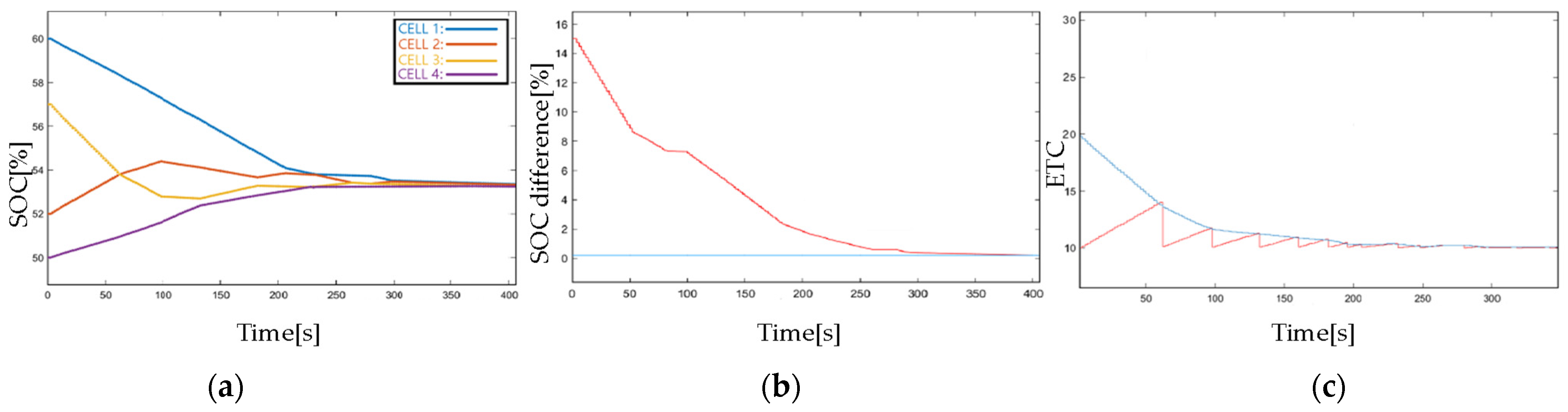
The simulation results with ETM are captured in Figure 15. As shown in Figure 15, the battery pack balancing is terminated while the SOC difference is slowly brought down to 0.2 to prevent excessive battery balancing. The comparisons between TTM and ETM can be conducted by distinguishing the results of Figure 11a and Figure 15a. The balancing process is completed in 488 s under the TTM strategy, whereas it only takes 402 s while using the ETM strategy. As a result, the balancing speed is accelerated and the number of actuator updates is decreased, which is unquestionably beneficial to the battery health. In Figure 15c, when the red-marked and the blue-labeled intersect, the error will be instantly reset to zero and an update of the actuator is triggered simultaneously. The equalization system will be guided by using the latest sampled data. Compared with the TTM strategy with an hs update period, much more than hs is available for the update in the ETM strategy, which has significantly released the computational complexity.
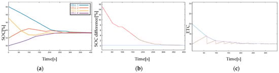
Figure 15.
Simulation results with the coefficient of Case 1 by using ETM: (a) SOC response in standby mode, (b) SOC difference and the average SOC of the pack in standby mode. (c) The ETC dynamics in standby mode.
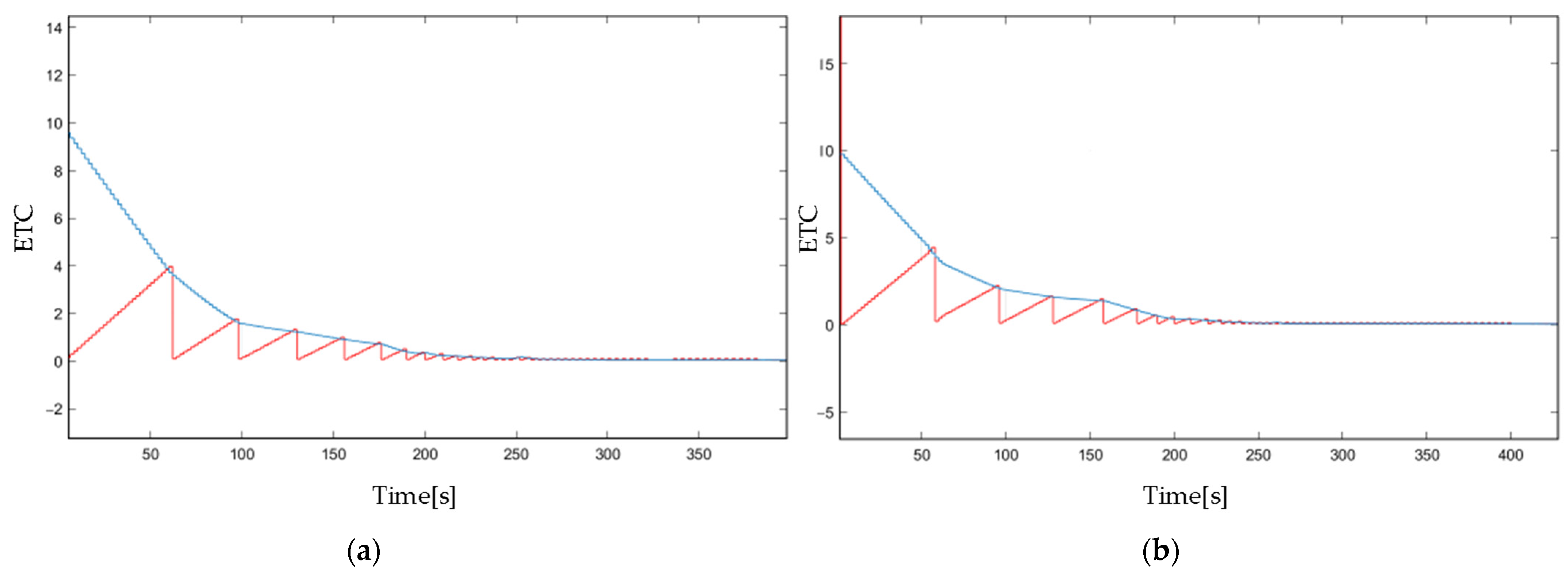
Figure 16 shows the ETC relation under charging and discharging mode. Figure 17a,b show the battery balancing dynamics under the ETM strategy during charging and discharging operations, respectively. The charging and discharging current are set to be 0.05A/−0.05A—the same as the TTM strategy. Compared with the TTM strategy, the time required for battery equalization to reach consensus is significantly decreased by using the ETM strategy in both charging and discharging modes. The comparison is statistically recorded in Table 3.
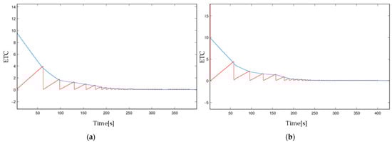
Figure 16.
Simulation results with coefficient of Case 1 by using ETM: (a) The ETC response in the charging mode, (b) The ETC response in the discharging mode.
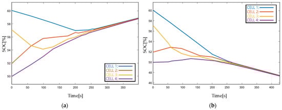
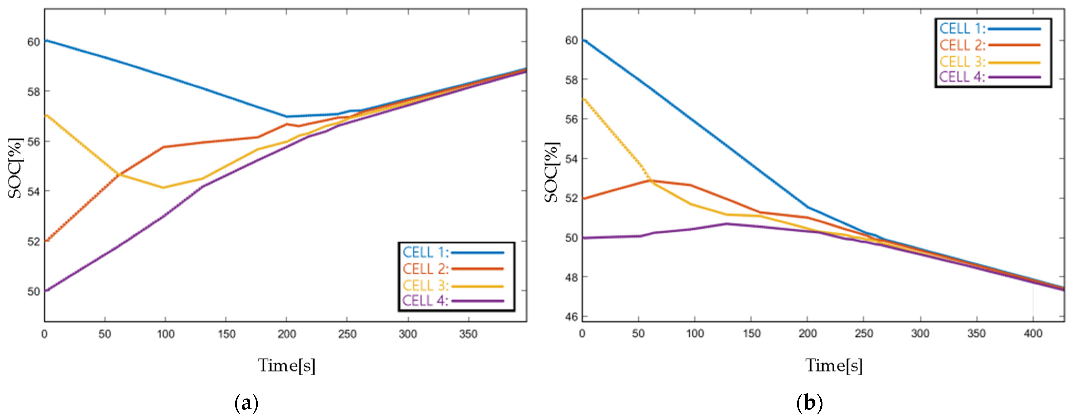
Figure 17.
Simulation results with the coefficient of Case 1 by using ETM: (a) SOC response in the charging mode, (b) SOC response in the discharging mode.
Table 3.
Comparison between TTM and ETM.
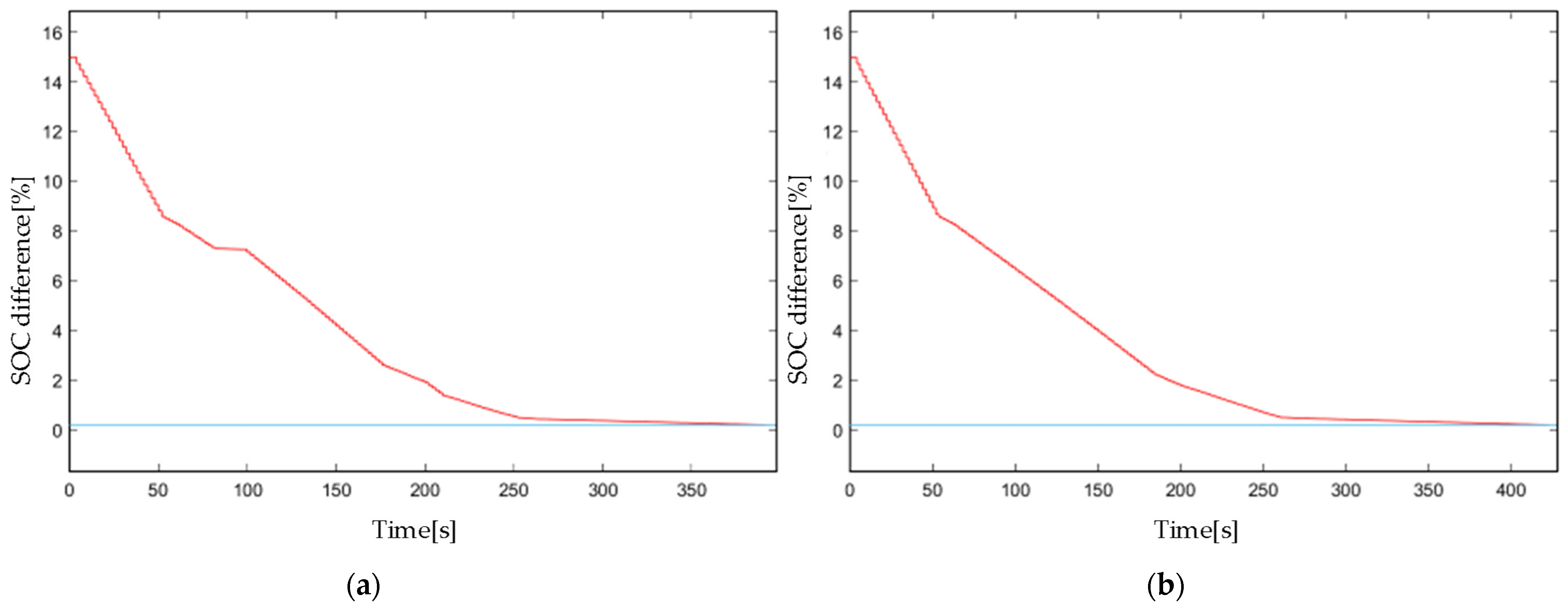
The SOC difference responses in the charging and discharging mode by using ETM with initial Case 1 are presented in Figure 18. As shown, the SOC differences reach zero rapidly and it shows non-linear features over time, attributed to the inherent characteristics of ETM.
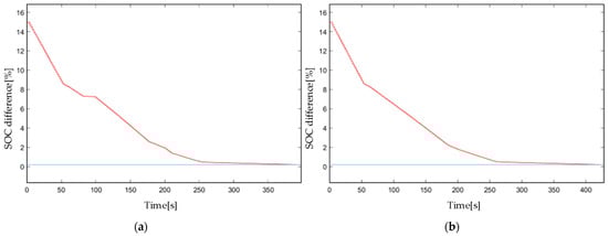
Figure 18.
Simulation results with the coefficient of Case 1 by using ETM: (a) SOC difference response in the charging mode, (b) SOC difference response in the discharging mode.
As shown in Table 3, the equalizing speed of the ETM strategy is about 22.1% faster than the TTM strategy in standby mode; this advantage will result in about a 13.1% faster equalizing speed in the charging and discharging mode, respectively. These data indicate that the ETM strategy effectively speeds up the balancing speed of the battery pack and obtains a 10.9% increase over the TTM strategy.
6. Hardware-in-the-Loop Results
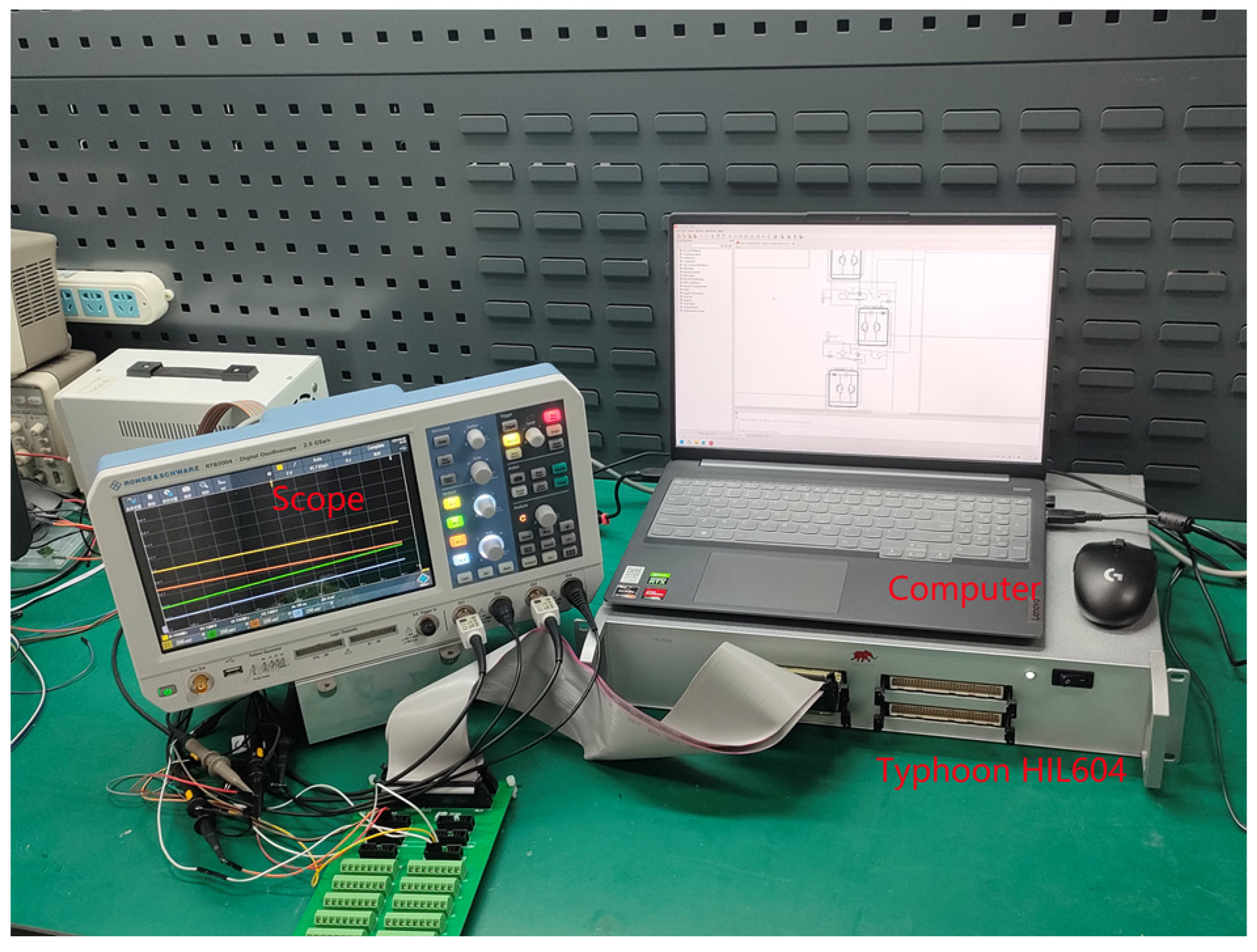
To investigate the cell balancing performance after using the proposed ETM strategy, the experimental verification by using CHIL is implemented. The CHIL experimental hardware platform is shown in Figure 19. The battery balancing topology is generated in Typhoon HIL604. The sampling frequency is set to 10 kHz, the battery capacity is designed as about 1.2 Ah, the initial voltage of the battery while the cell is fully charged is set as 3.6 v, and the parameters of 18,650 lithium batteries are adopted in HIL604 experiments. The initial SOC value of the battery follows the specification of Case 1 in Table 2.

Figure 19.
Hardware platform of CHIL experiment.
The definition of equalizing current in the experiments is designed as follows:
In order to protect the battery, the upper bound of the balancing current Imax is necessary to be designed to prevent overcharging, over-discharging, and short-circuiting.
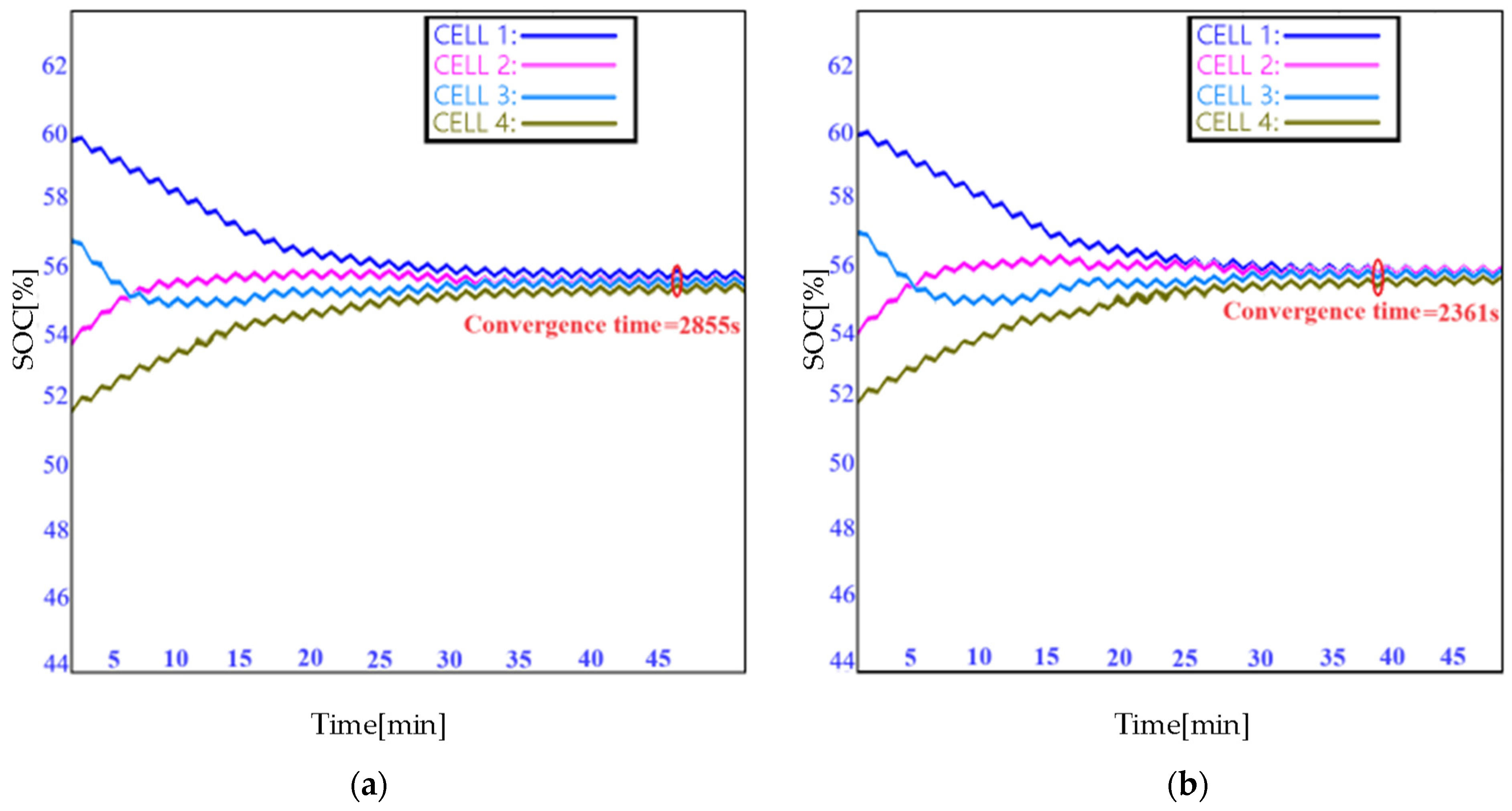
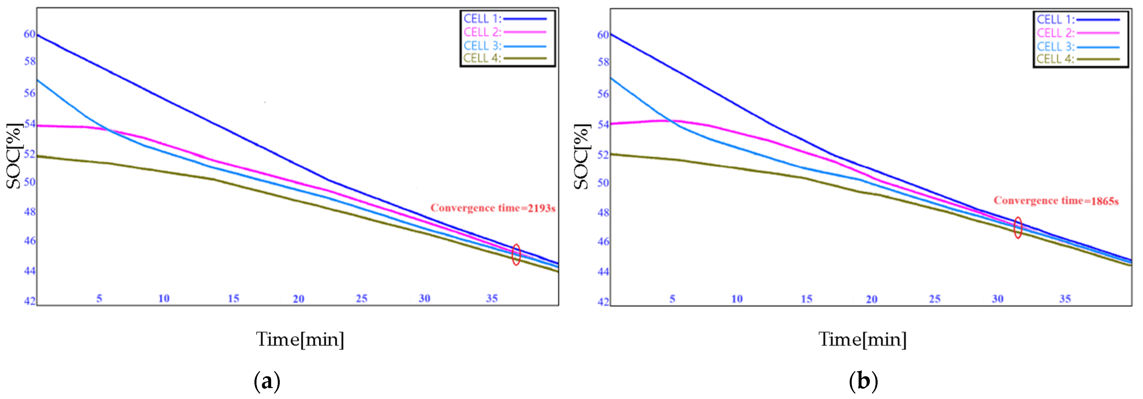
Figure 20a shows the SOC dynamical trajectory in the TTM equalizing process and the convergence time is 2855s. The convergence time of the ETM equalizing method goes to 2361 s, as shown in Figure 20b. It is obvious that this equalization time by using ETM is much shorter than TTM’s. From this perspective, the pack balancing obtained by ETM is superior to the TTM one in terms of equalization efficiency.
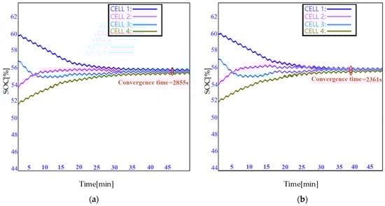
Figure 20.
SOC response of the cells in a pack (a) under the external dynamic current of TTM; (b) under the external dynamic current of ETM.
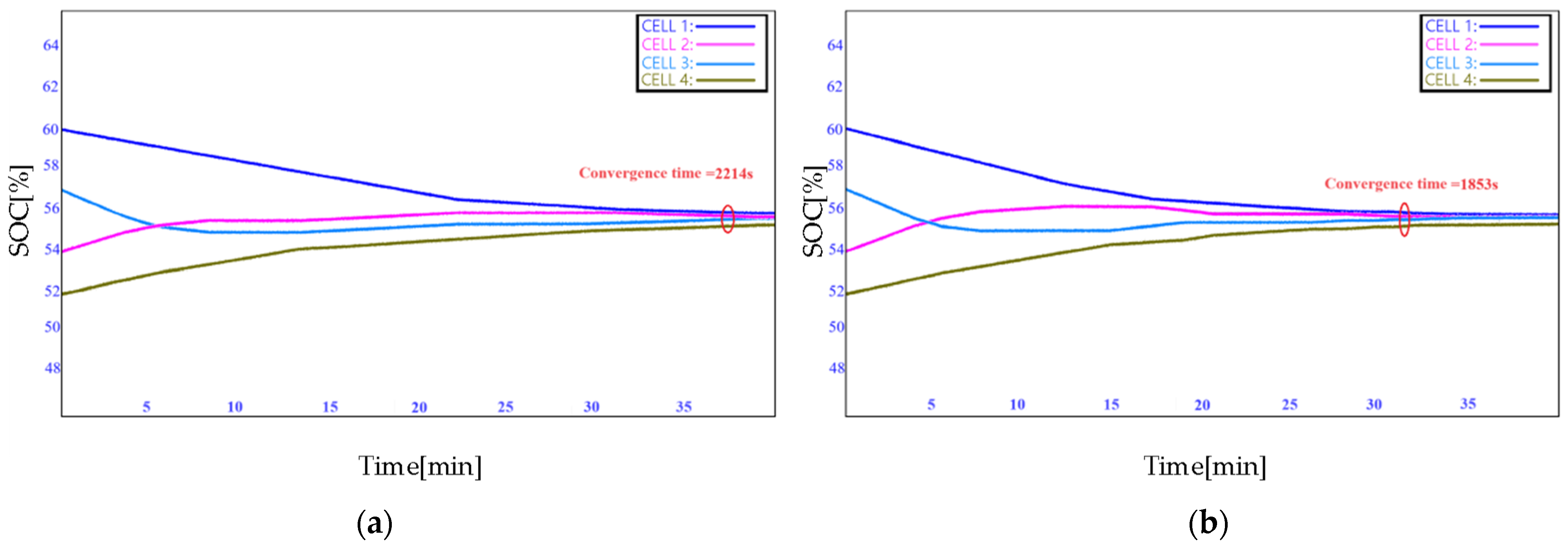
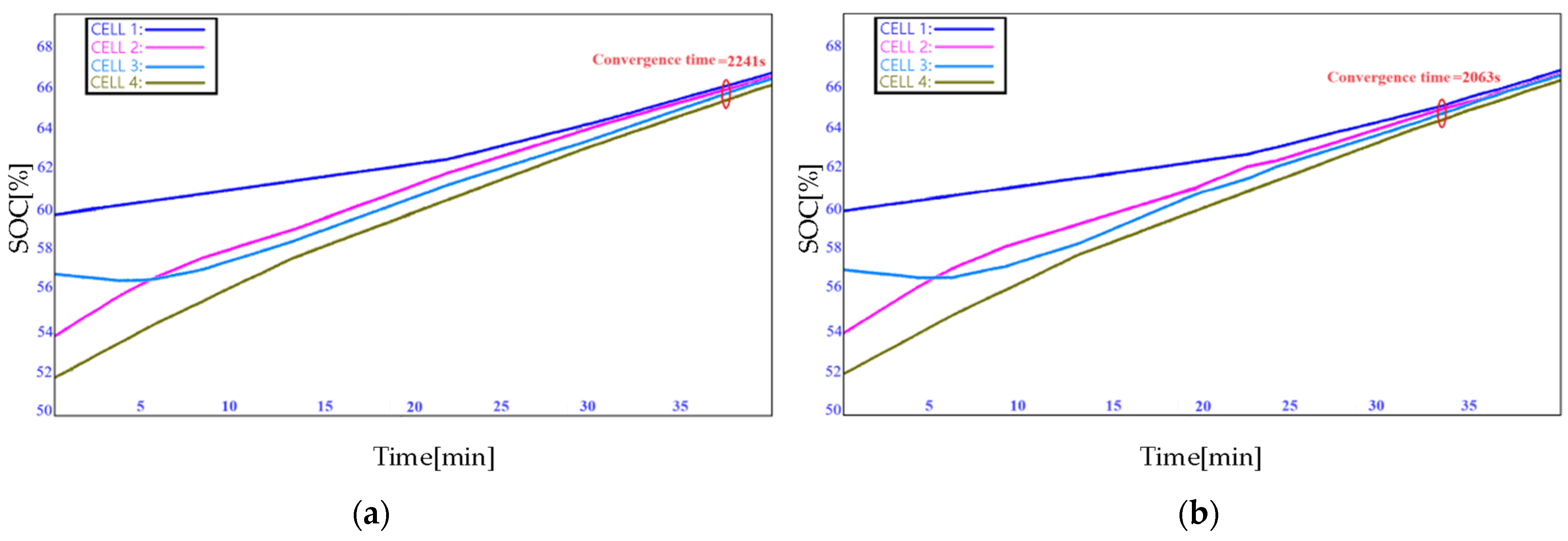
It can be seen from Figure 21, Figure 22 and Figure 23 that the ETM strategy stimulates a faster balancing speed than the TTM strategy. In the case of standby, charging, and discharging, the equalizing speed is increased by about 9% and the equalization time is shortened.
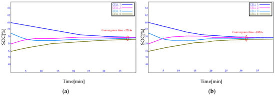
Figure 21.
SOC response in (a) standby mode of TTM, (b) standby mode of ETM.
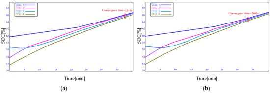
Figure 22.
SOC response in (a) charging mode of TTM, (b) charging mode of ETM.
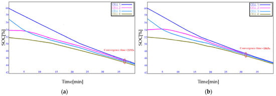
Figure 23.
SOC response in (a) discharging mode of TTM, (b) discharging mode of ETM.
In the SOC-based consensus strategy, the control implementation and ETM are mostly based on simulation, rarely reported by experiment. This paper verifies the theory and simulation through hardware-in-the-loop experiments and provides an effective way to demonstrate the large-scale battery system.
In conclusion, the effectiveness and rapidity of the proposed ETM strategy of cell balancing are validated by CHIL experiments. Compared with the traditional TTM strategy, the equalizing time and the update frequency of the actuator have been remarkably reduced.
From Table 3 and Figure 20, Figure 21, Figure 22 and Figure 23, it can be concluded that the ETM strategy has a faster equalizing speed than that of the TTM strategy, which can save the balancing time so that better consistency is obtained for all cells in a pack. Figure 15c and Figure 16 show that the PWM signal input into the MOSFET of ICE will change its value to control the balancing system only when the red-marked and the blue-labeled intersect. Whereas The update frequency of TTM is related to the sampling time h instead. It is much less than that of TTM, which can reduce the computing burden of the PWM signal.
7. Conclusions
From the perspective of a multi-agent system, the battery pack is designed as a multi-agent system in this paper, regarding cells as nodes and ICEs as edges. From this, a consensus algorithm based on SOC sampled data is proposed for accelerating the equalizing speed of the cells in a pack. Furthermore, an SOC-based consensus equalizing strategy with ETM is proposed. The convergence of the proposed two strategies is evaluated by using the Lyapunov principle. As an appropriate sampling interval is designed, the consensus performance of the battery cells is significantly improved. Finally, the validity of TTM and ETM is verified through simulations and CHIL experiments. The equalizing time and some other parameters are adopted as the evaluation indexes. The results show that the equalizing speed by using the proposed ETM strategy is faster than that of TTM mostly due to the decreased update frequency of the actuator. Overall, the novel idea of the ETM equalization strategy provides a satisfactory solution and fits well with established theories and experimental results.
Author Contributions
Conceptualization, Y.Z. and L.Y.; methodology, N.H. and L.Y.; validation, F.Z. and L.Y.; formal analysis, Y.Z., L.Y. and F.Z.; investigation, F.Z.; resources, N.H.; writing—original draft preparation, L.Y.; writing—review and editing, L.Y.; supervision, Y.Z.; project administration, Y.Z. All authors have read and agreed to the published version of the manuscript.
Funding
This research is supported by the National Natural Science Foundation of China (Grant No.51877058), the Natural Science Foundation of Zhejiang Province (Grant LZ22F030005), the Fundamental Research Funds for the Provincial Universities of Zhejiang (Grant GK239909299001-006), China.
Data Availability Statement
No new data were created.
Conflicts of Interest
The authors declare no conflict of interest.
Nomenclature and Abbreviations
| i, j | Battery serial numbers |
| The duty cycle used to power the PWM signal of MOSFET j in ith ICE | |
| The Laplacian matrix of the system | |
| MOSFET | Metal-oxide semiconductor field-effect transistor. |
| Q1, Q2 | The MOSFETs in one ICE. |
| C1 | The capacitance in one ICE |
| L1, L2 | The inductance in one ICE |
| BT1, BT2 | The cells during the equalizing process in one ICE |
| The measurement error of cell i. | |
| The control input of the equalizing system. | |
| The SOC state during the equalizing process. | |
| The eigenvalue of Laplacian matrix L. | |
| TTM | Time-triggered mechanism |
| ETM | Event-triggered mechanism |
| ETC | Event-triggered condition |
| SOC | State of charge |
| ICE | Individual cell equalizer |
| PWM | Pulse width modulation |
| CEP | Centralized event processor |
| CHIL | Control hardware-in-the-loop |
| ZOH | Zero-order hold |
Appendix A
Define:
There is an inconsistency: . We have:
let , it has: . By designing reasonable control gain , the system converges to consensus.
Appendix B
According to the equalizing topology defined before, we define the Lyapunov function as:
For , it is obtained as:
The sampling period h can be defined from the formula above.
Let , ETC can be computed by .
By LaSalle’s invariance principle, it can be deduced that, for , the consensus of the system is validated.
Appendix C
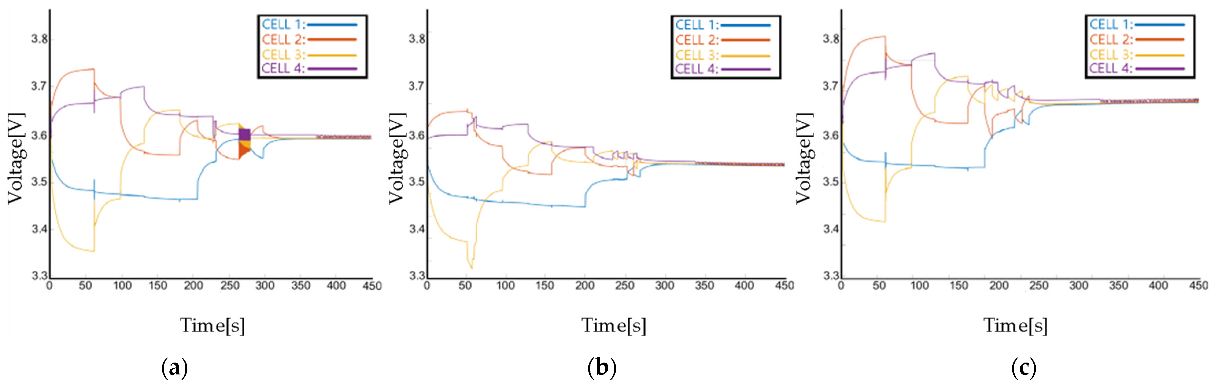
Figure A1, Figure A2, Figure A3 and Figure A4 show the equalizing current and equalizing voltage of each cell in different modes, such as standby mode, charging mode and discharging mode. These figures clearly show the relationship among equalizing current, voltage and the external current. In Figure A1 and Figure A2, the equalizing current of each cell under TTM and ETM all converges to a stable value. The steady-state current difference between standby mode and charging/discharging mode is exactly the predefined external current. In Figure A3 and Figure A4, the voltage of each cell under TTM and ETM all converges to a stable value with a decreasing difference.
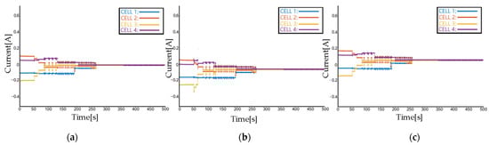
Figure A1.
The equalizing current of each cell by using TTM: (a) in standby mode, (b) in discharging mode, (c) in charging mode.
Figure A1.
The equalizing current of each cell by using TTM: (a) in standby mode, (b) in discharging mode, (c) in charging mode.
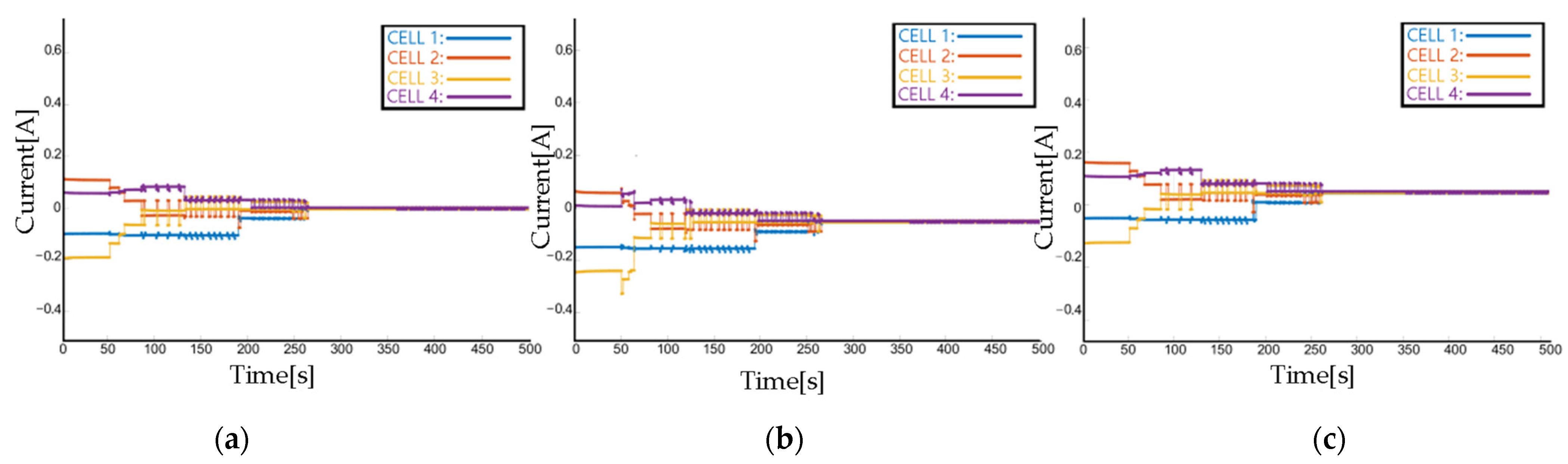
Figure A2.
The equalizing current of each cell by using ETM: (a) in standby mode, (b) in discharging mode, (c) in charging mode.
Figure A2.
The equalizing current of each cell by using ETM: (a) in standby mode, (b) in discharging mode, (c) in charging mode.
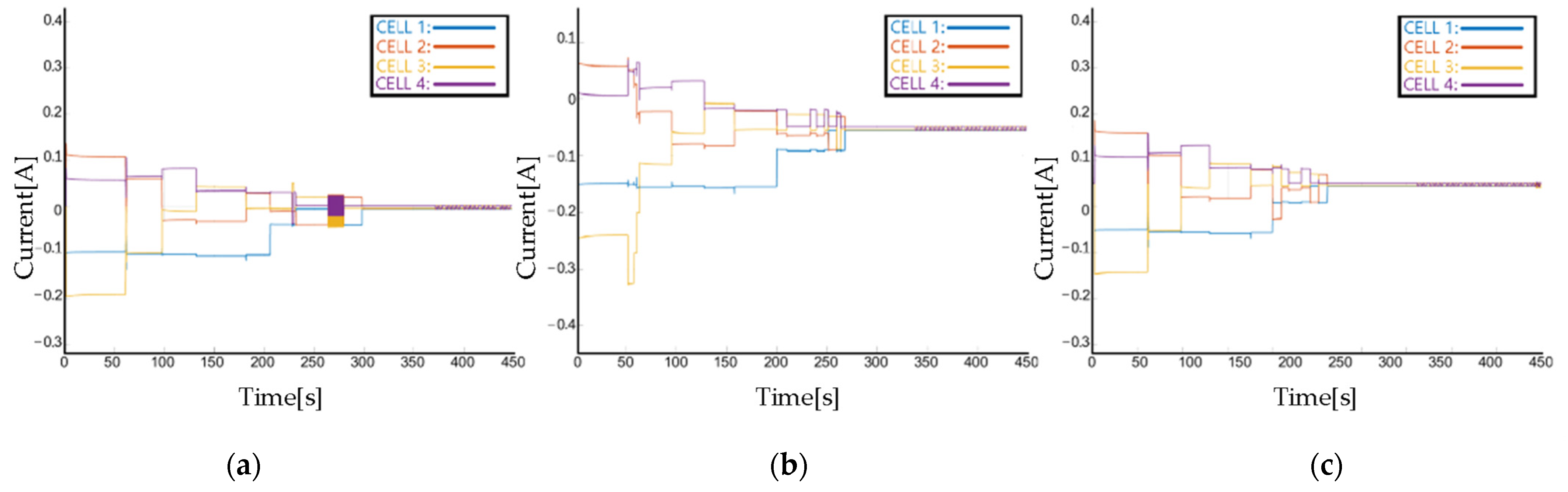
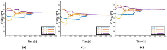
Figure A3.
The voltage of each cell by using TTM: (a) in standby mode, (b) in discharging mode, (c) in charging mode.
Figure A3.
The voltage of each cell by using TTM: (a) in standby mode, (b) in discharging mode, (c) in charging mode.
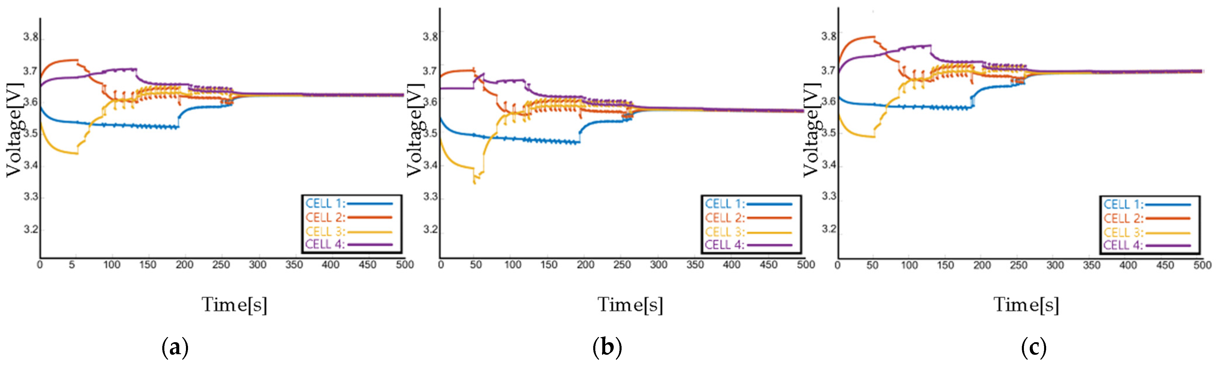
Figure A4.
The voltage of each cell by using ETM: (a) in standby mode, (b) in discharging mode, (c) in charging mode.
Figure A4.
The voltage of each cell by using ETM: (a) in standby mode, (b) in discharging mode, (c) in charging mode.
References
- Hannan, M.A.; Hoque, M.D.M.; Hussain, A.; Yusof, Y.; Ker, A.P.J. A State of the art and energy management system of lithium-ion batteries in electric vehicle applications: Issues and recommendations. IEEE Access 2018, 6, 19362–19378. [Google Scholar] [CrossRef]
- Lipu, M.H.; Hannan, M.; Hussain, A.; Hoque, M.; Ker, P.J.; Saad, M.; Ayob, A. A review of state of health and remaining useful life estimation methods for lithium-ion battery in electric vehicles: Challenges and recommendations. J. Clean. Prod. 2018, 205, 115–133. [Google Scholar] [CrossRef]
- Li, Y.; Han, Y. A module-integrated distributed battery energy storage and management system. IEEE Trans. Power Electron. 2016, 31, 8260–8270. [Google Scholar] [CrossRef]
- Zhang, C.; Wei, Y.-L.; Cao, P.-F.; Lin, M.-C. Energy storage system: Current studies on batteries and power condition system. Renew. Sustain. Energy Rev. 2018, 82, 3091–3106. [Google Scholar] [CrossRef]
- Ouyang, Q.; Han, W.; Zou, C.; Xu, G.; Wang, Z. Cell balancing control for lithium-ion battery packs: A hierarchical optimal approach. IEEE Trans. Ind. Inform. 2019, 16, 5065–5075. [Google Scholar] [CrossRef]
- Caspar, M.; Eiler, T.; Hohmann, S. Systematic comparison of active balancing: A model-based quantitative analysis. IEEE Trans. Veh. Technol. 2016, 67, 920–934. [Google Scholar] [CrossRef]
- Feng, F.; Teng, S.; Liu, K.; Xie, J.; Xie, Y.; Liu, B.; Li, K. Co-estimation of lithium-ion battery state of charge and state of temperature based on a hybrid electrochemical-thermal-neural-network model. J. Power Sources 2020, 455, 227935. [Google Scholar] [CrossRef]
- Yan, J.; Cheng, Z.; Xu, G.; Qian, H.; Xu, Y. Fuzzy control for battery equalization based on state of charge. In Proceedings of the 2010 IEEE 72nd Vehicular Technology Conference—Fall, Ottawa, ON, Canada, 6–9 September 2010; pp. 1–7. [Google Scholar]
- Balasingam, B.; Ahmed, M.; Pattipati, K. Battery management systems—Challenges and some solutions. Energies 2020, 13, 2825. [Google Scholar] [CrossRef]
- Li, Y.; Xu, J.; Mei, X.; Wang, J. A unitized multi-winding transformer-based equalization method for series-connected battery strings. IEEE Trans. Power Electron. 2019, 34, 11981–11989. [Google Scholar] [CrossRef]
- Qu, F.; Luo, Q.; Liang, H.; Mou, D.; Sun, P.; Du, X. Systematic overview of active battery equalization structures: Mathematical modeling and performance evaluation. IEEE Trans. Energy Convers. 2022, 37, 1685–1703. [Google Scholar] [CrossRef]
- Ma, Y.; Duan, P.; Sun, Y.; Chen, H. Equalization of lithium-ion battery pack based on fuzzy logic control in electric vehicle. IEEE Trans. Ind. Electron. 2018, 65, 6762–6771. [Google Scholar] [CrossRef]
- Hua, Y.; Zhou, S.; Cui, H.; Liu, X.; Zhang, C.; Xu, X.; Ling, H.; Yang, S. A comprehensive review on inconsistency and equalization technology of lithium-ion battery for electric vehicles. Int. J. Energy Res. 2020, 44, 11059–11087. [Google Scholar] [CrossRef]
- Lee, K.-M.; Lee, S.-W.; Choi, Y.-G.; Kang, B. Active balancing of Li-ion battery cells using transformer as energy carrier. IEEE Trans. Ind. Electron. 2016, 64, 1251–1257. [Google Scholar] [CrossRef]
- Dong, B.; Li, Y.; Han, Y. Parallel architecture for battery charge equalization. IEEE Trans. Power Electron. 2014, 30, 4906–4913. [Google Scholar] [CrossRef]
- Barreras, J.V.; de Castro, R.; Wan, Y.; Dragicevic, T. A consensus algorithm for multi-objective battery balancing. Energies 2021, 14, 4279. [Google Scholar] [CrossRef]
- Ouyang, Q.; Chen, J.; Zheng, J.; Hong, Y. SOC estimation-based quasi-sliding mode control for cell balancing in lithium-ion battery packs. IEEE Trans. Ind. Electron. 2017, 65, 3427–3436. [Google Scholar] [CrossRef]
- McCurlie, L.; Preindl, M.; Emadi, A. Fast model predictive control for redistributive lithium-ion battery balancing. IEEE Trans. Ind. Electron. 2016, 64, 1350–1357. [Google Scholar] [CrossRef]
- Jinlei, S.; Wei, L.; Chuanyu, T.; Tianru, W.; Tao, J.; Yong, T. A novel active equalization method for series-connected battery packs based on clustering analysis with genetic algorithm. IEEE Trans. Power Electron. 2021, 36, 7853–7865. [Google Scholar] [CrossRef]
- Hoque, M.M.; Hannan, M.A.; Mohamed, A. Charging and discharging model of lithium-ion battery for charge equalization control using particle swarm optimization algorithm. J. Renew. Sustain. Energy 2016, 8, 065701. [Google Scholar] [CrossRef]
- Li, S.; Shang, Y.; Duan, B.; Chen, G.; Zhang, Q.; Zhang, C. A state-of-charge uniformity control method for energy storage batteries based on distributed cooperative control. In Proceedings of the 2021 China Automation Congress (CAC), Beijing, China, 22–24 October 2021. [Google Scholar]
- Khazaei, J.; Nguyen, D.H. Multi-agent consensus design for heterogeneous energy storage devices with droop control in smart grids. IEEE Trans. Smart Grid 2017, 10, 1395–1404. [Google Scholar] [CrossRef]
- Qian, Y.-Y.; Premakumar, A.V.P.; Wan, Y.; Lin, Z.; Shamash, Y.A.; Davoudi, A. Dynamic Event-Triggered Distributed Secondary Control of DC Microgrids. IEEE Trans. Power Electron. 2022, 37, 10226–10238. [Google Scholar] [CrossRef]
- Lee, S.; Kim, J.; Lee, J.; Cho, B. State-of-charge and capacity estimation of lithium-ion battery using a new open-circuit voltage versus state-of-charge. J. Power Sources 2008, 185, 1367–1373. [Google Scholar] [CrossRef]
- Peng, J.; Luo, J.; He, H.; Lu, B. An improved state of charge estimation method based on cubature Kalman filter for lithium-ion batteries. Appl. Energy 2019, 253, 113520. [Google Scholar] [CrossRef]
- Sun, L.; Li, G.; You, F. Combined internal resistance and state-of-charge estimation of lithium-ion battery based on extended state observer. Renew. Sustain. Energy Rev. 2020, 131, 109994. [Google Scholar] [CrossRef]

Disclaimer/Publisher’s Note: The statements, opinions and data contained in all publications are solely those of the individual author(s) and contributor(s) and not of MDPI and/or the editor(s). MDPI and/or the editor(s) disclaim responsibility for any injury to people or property resulting from any ideas, methods, instructions or products referred to in the content. |
© 2023 by the authors. Licensee MDPI, Basel, Switzerland. This article is an open access article distributed under the terms and conditions of the Creative Commons Attribution (CC BY) license (https://creativecommons.org/licenses/by/4.0/).