1. Introduction
Radar-absorbing honeycomb structures have been widely used in practical stealth engineering due to their special characteristics of a low density, a good strength, a light weight, and stiffness-to-weight ratios. Due to the uniformly distributed multiscale problem caused by the extremely thin and multilayered unit cell’s wall in the cellular structure of a honeycomb, it is challenging to simulate objects with honeycomb structures. Without the special treatment of the unit cell’s wall, the direct modeling of honeycomb structures using conventional full-wave numerical methods, the finite-difference time-domain (FDTD) method [
1], the finite element method (FEM) [
2], the method of moments (MoM) [
3], the hybrid finite element–boundary integral–multilevel fast multipole algorithm (FE-BI-MLFMA) [
4], etc., results in a serious computational burden. Volume discretization methods, such as the FEM and FDTD, need to treat each unit cell as an inhomogeneous body, which consists of a unit cell’s wall and background filling material, and then mesh each material into elements accordingly. Due to the thin unit cell’s wall, extremely fine meshes are required, resulting in a computational burden. When surface discretization methods, such as the MoM, are used, the surfaces of both the coating and the thin unit cell’s wall are required to be discretized into triangular patches. Since the overall surface area of a honeycomb core is large, computational burdens arise when modeling large honeycomb structures. As the target size increases, the computational resources required by state-of-the-art numerical methods for modeling honeycomb structures increase dramatically. Conventional numerical methods are not applicable for modeling practical inhomogeneous objects with honeycomb structures, even though their computational capability has been improved significantly with the development of fast direct solvers [
5,
6,
7] and fast domain-decomposition-based methods [
8,
9,
10,
11,
12,
13,
14].
To overcome this problem, homogenization methods are proposed, such as the Maxwell Garnett theory, the Bruggeman theory, the Hashin–Shtrikman (HS) variational theory, and the strong fluctuation theory [
15,
16,
17,
18,
19,
20,
21,
22]. In these types of methods, the effective permittivity and permeability of the honeycomb is first derived by using a certain homogenization theory. Then, the conventional honeycomb structure is treated as a homogenous body and then simulated with a certain kind of numerical method, FEM, FDTD, etc. Homogenization methods can be highly efficient under the premise of providing reliable equivalent electromagnetic parameters using homogenization theories. However, state-of-the-art theories assume that the incident wavelength is much longer than the period of the structure. Additionally, the edge effect of these unit cells at the boundary of the honeycomb is also ignored. Therefore, although highly efficient, the accuracy and flexibility of homogenization methods are not well ensured, especially when the honeycomb structure is bent or cut into an irregular shape, or the incident microwave angle of a unit cell’s axis is large, which is quite important in practical engineering.
Recently, a modeling method based on the resistive sheet boundary conditions (RSBCs) has been presented for simulating electromagnetic filed interactions with honeycomb structures, in which the main computational burden is removed by reducing unit cell walls into zero-thickness faces using the RSBCs [
23]. This work starts by simplifying the honeycomb model by reducing the multilayer and multimedia unit cell’s wall into a zero-thickness surface with the aid of an approximate boundary condition, which relates the tangential components of the electric field and magnetic field to a surface impedance. With this method, the edge effect of the unit cells at the boundary is considered, and the flexibility and accuracy are significantly improved compared with those of homogenization approaches. However, the crucial demand of keeping the original cellular structure results in a meshing burden and a computational deficiency in certain cases.
Each single state-of-the-art approach for modeling electromagnetic filed interactions with honeycomb structures has a main advantage and disadvantage. In this paper, based on our earlier work on homogenization approaches in [
22] and the RSBC approach in [
23], we propose a novel hybrid modeling approach for modeling electromagnetic field interactions with honeycomb structures. The proposed hybrid approach starts by decomposing the original honeycomb structure into the inner and outer subregions. The inner subregion should be regularly shaped and is homogenized as an anisotropic medium, with the relative permittivity tensors evaluated by using the Hashin–Shtrikman and the Mori–Tanaka formula approaches in a local coordinate system; we name this the homogenization region [
22]. The outer subregion is modeled using the RSBC approach proposed in [
23], noted as the RSBC region for short, where each unit cell’s wall of the honeycomb structures is replaced with a zero-thickness resistive sheet. The two subregions are glued together using the Robin-type transmission conditions on nonconformal meshed interfaces. Then, each subregion is further divided into smaller subdomains and simulated following the noncomformal domain decomposition FE-BI-MLFMA [
13,
23]. The performance and accuracy of the proposed method are demonstrated with several numerical examples, including a complicated high-definition stealth unmanned aerial vehicle (UAV) scale model with honeycomb structures. The numerical results show an increased accuracy or efficiency of the proposed hybrid approach compared to that of a single conventional approach.
2. Formulation
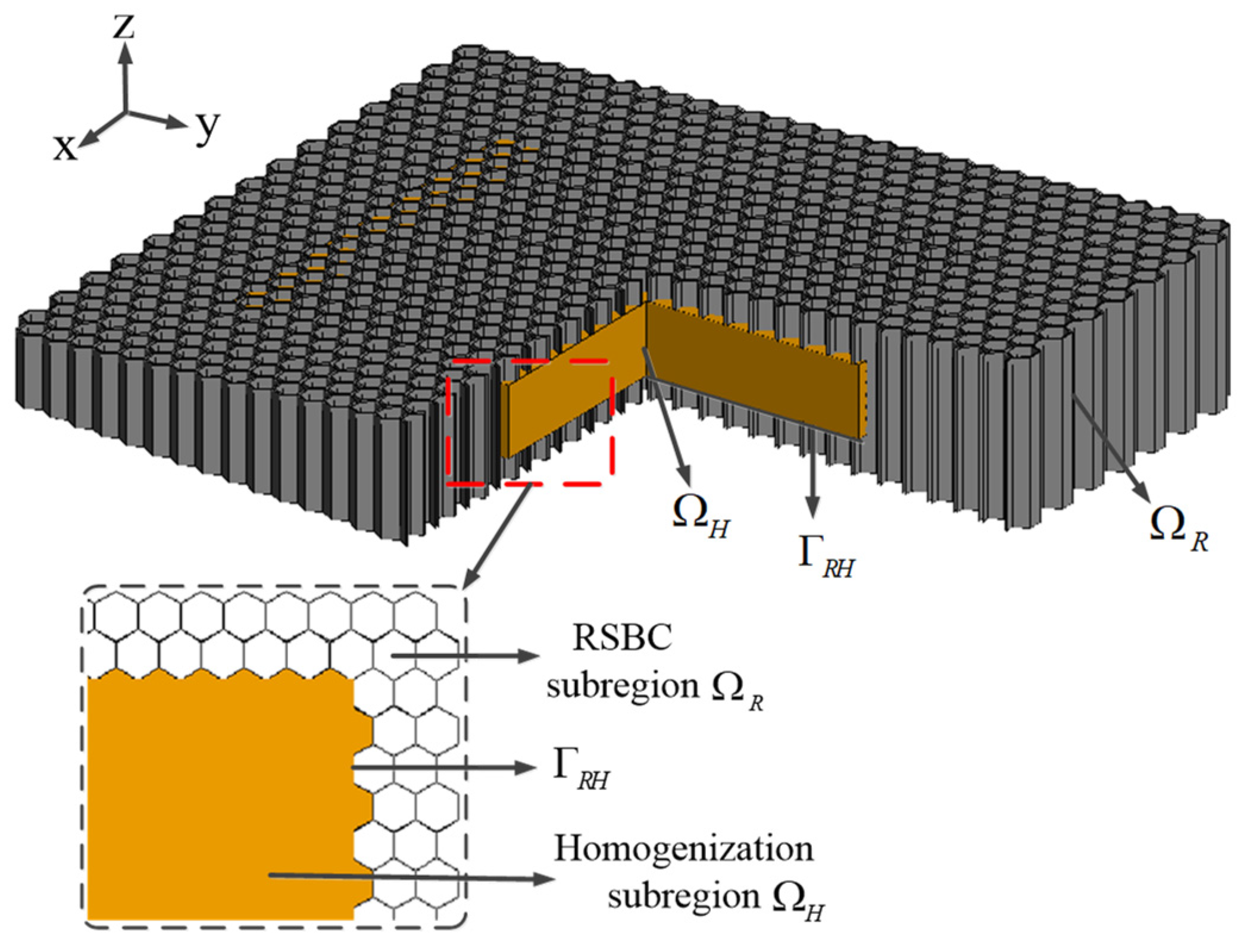
A typical honeycomb composite is illustrated in
Figure 1. The unit cells are composed of aramid paper with lossy coatings on the surface, or they are directly made using additive manufacturing technology with microwave absorbing materials, which is better known as 3D printing. In practice, the aperture size of a unit cell is at the millimeter level, and the thickness of the multilayer unit cell’s wall is smaller than 0.1 mm, resulting in challenging multimaterial and multiscale problems in computational electromagnetics. By combining the homogenization approach and the RSBC-based numerical modeling approach together, a novel hybrid numerical modeling method for computing electromagnetic scattering by objects with honeycomb structures is proposed, and it exhibits both the high accuracy and flexibility of the conventional RSBC-based approach and the high efficiency of the homogenization-based approach. Details of the proposed hybrid approach are provided below.
The proposed hybrid approach is also based on the FE-BI-MLFMA. According to the FE-BI-MLFMA, the honeycomb structure is divided into the interior body region and the exterior surface region by the outer surface of the object. In the proposed hybrid modeling approach, the interior body region of a honeycomb structure is decomposed into the RSBC subregion and the homogenization subregion, as shown in
Figure 1. Note that, on the boundary interface between the inner and outer subregions, the cellular structure characteristic of the honeycomb is kept to ensure that the boundary condition of all the unit cells in the homogenization subregion remains the same. Without losing generality, we suppose that the honeycomb considered is made of non-magnetic materials, meaning
.
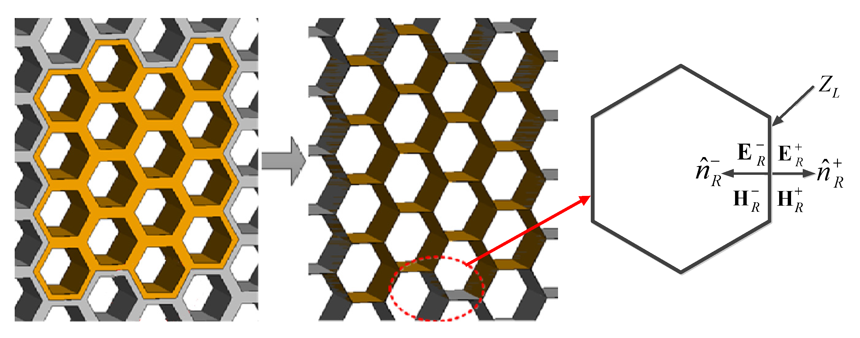
For the RSBC subregion
, we introduce the approximate RSBCs to reduce the resistively coated thin wall to a zero-thickness surface
, as shown in
Figure 2. Then, electromagnetic field discontinuities across the
can be described using the RSBC as follows [
23]:
where
,
.
and
are the electric fields and magnetic fields on two sides of the reduced RSBC surface residing on the touching interface of two unit cells’ walls.
is the surface impedance of the wall, and
denotes the outward unit vector normal to the surface.
can be evaluated as follows:
where
and
denote the permittivity and thickness of the unit cell’s wall, and
is the angular frequency of the incident planewave.
For the homogenization subregion
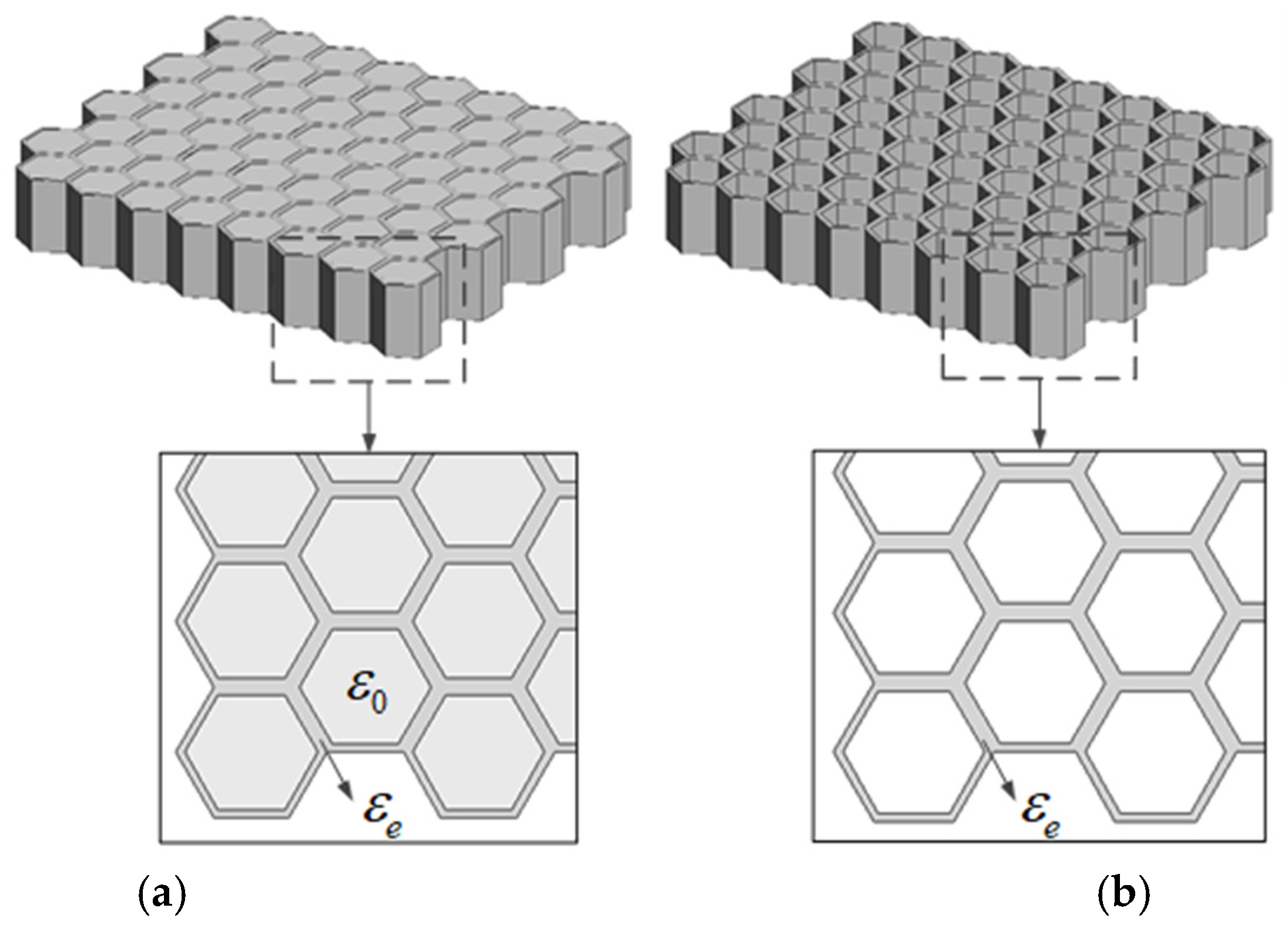
, it is homogenized as an anisotropic medium, with the effective permittivity
given by following the H-S and the M-T formulae [
22]:
With
where
and
are the volume fraction and relative permittivity of the unit cell’s wall,
l denotes the height of the honeycomb, and t is the width between the two parallel unit cell walls, respectively.
Obviously, in practice, it is hard to generate conformal meshes on an interface shared by both the RSBC region
and the homogenization region
, as noted
in
Figure 1; we need to introduce the Robin-type transmission conditions allowing nonconformal meshes to couple them:
where
and
are the unit normal vectors at the interface pointing to the exterior regions of the subregions
and
, respectively.
The boundary value problem (BVP) for a subdomain in
is described as follows:
where
is the interface with BI, and
and
are the relative permittivity and relative permeability, respectively. Note that Equation (13) is obtained using Equations (1) and (2). The fields in the RSBC region are formulated into an equivalent variational problem:
The BVP for fields in
can be obtained in the same way except that Equation (13) is removed, and
is used instead of
:
The fields in the exterior region (typically the outer surface of the object) are formulated into the combined field integral equation (CFIE) [
4]:
With
where PV denotes the Cauchy principle value integration,
is Green’s function in free space, and
is the external incident plane wave.
The final matrix equation system can be obtained by combining the equivalent variational problems for the RSBC in Equation (15), the homogenization subregion in Equation (16), and the CFIE in (17). The vector FEM on tetrahedral meshes and the Rao–Wilton–Glisson (RWG) basis functions on triangle-patch meshes are used for discretizing the FEM and the BI domains, respectively. To improve the computational efficiency of the method, the idea of the noncomformal domain decomposition FE-BI-MLFMA is adopted. Both the RSBC and the homogenization subregions are further divided into smaller subdomains, and two neighbor subdomains are also coupled by using Robin transmission conditions. By properly discretizing all the related equations, including the FEM equivalent variational problem, the Robin boundary conditions, and the CFIE, and assembling all subdomain matrix equation systems together, the final equation system is obtained and then solved with the aid of MLFMA. A detailed description can be found in [
23].
As a hybrid approach of the existing RSBC approach and the homogenization approach, the proposed approach retains the advantages of each approach while eliminating their main disadvantage as follows:
In the RSBC, although the volume of the thin unit cell’s wall is removed, we still need to mesh the zero-thickness resistive sheet with the mesh density proportional to the wavenumber in the high-contrast thin-wall materials. However, in the homogenization approach, we only need to mesh the homogenous media with the mesh density proportional to the wavenumber in the media after homogenization. The mesh density of the latter is larger than that of the former, significantly reducing the total number of FEM unknowns. Consequently, the proposed approach yields a better efficiency than the conventional RSBC approach.
State-of-the-art homogenization theories ignore the edge effect of these unit cells at the boundary of the honeycomb. Such an assumption causes a larger error when the incident angle of the unit cell’s axis of honeycomb structures is large, which is important in practical engineering. Additionally, when the honeycomb boundary is irregularly shaped, the volume fraction of the space occupied by the wall in each honeycomb unit cell is nonuniform, and it is hard to evaluate it accurately. Therefore, the flexibility of the homogenization approach is not as good as that of the RSBC approach. Hence, by using the RSBC on the boundary region, the proposed hybrid approach is more flexible and accurate than the homogenization approach.
Due to the above reasons, the proposed hybrid approach exhibits both the high accuracy and flexibility of the conventional RSBC-based approach and the high efficiency of the homogenization-based one at the same time.
3. Numerical Results
In this section, we design a series of numerical experiments to study the performance of the proposed approach. All the computations are performed on the Liuhui III computer (Beijing, China) at the Institute of Radio Frequency Technology and Software, Beijing Institute of Technology (BIT-IRFTS). It has 8 Intel Xeon Platinum 8276 CPU 2.20 GHz CPUs, with 28 cores for each CPU and 1 TByte memory. Without losing generality, we suppose that the honeycomb considered is made using 3D printing and that the unit cell’s wall is lossy and homogenous. In the case of the coated honeycomb, it contains at least two layers, that is, a Nomex honeycomb core and a lossy coating, and it can also be easily handled by using the effective surface impedance for the RSBC subregion or treated as a three-phase medium for the homogenization subregion.
Obviously, the proposed hybrid method balances accuracy and efficiency by combining the homogenization approach and the RSBC-based numerical modeling approach. Therefore, the overall accuracy of the proposed method depends on the ratio of the RSBC subregion to the total region. A larger RSBC modeling region brings a higher accuracy at the price of more unknowns and vice versa. Hence, we first need to determine the proper size of the RSBC modeling subregion to obtain a good accuracy and a high efficiency at the same time. We use the root mean square (RMS) to quantify the discrepancy between the reference data and the proposed method. The RMS function can be defined as follows:
where
is the monostatic angle, and
and
are the reference and calculated results.
Before carrying out numerical experiments, we need to choose proper reference data for evaluating the RMS of different methods. Since there are no analytical results for honeycomb structures and no available measurement data, we use the simulated results from the direct numerical modeling of the honeycomb structure without any simplification as the references. Among the different numerical methods, integral equation-based ones are believed to be accurate, as the Sommerfeld radiation condition is exactly incorporated into them through the use of an appropriate Green’s function. Among the various integral equation approaches, surface integral formulations are more attractive for impenetrable and homogeneous structures. Therefore, in this paper, the results obtained by using the MoM of commercial software FEKO are used as the reference data. To validate the accuracy of the MoM in FEKO for honeycomb structures, we compute the monostatic scattering using a honeycomb panel with a size of
with the MoM in FEKO and the FE-BI in HFSS, as is shown in
Figure 3. When the FE-BI in HFSS is used, each unit cell is treated as an inhomogeneous body consisting of a lossy material and background filling materials, typically vacuum-tight. Each material is modeled and meshed into tetrahedral elements accordingly. The computed VV-polarized monostatic RCSs are plotted in
Figure 4. As we can see in the figure, the numerical results obtained using the different methods are in excellent agreement. However, the MoM is faster than the FE-BI, as it only needs to discretize the target surface; thus, the number of unknowns is much less than that of the FEM. Hence, in the following experiments, only the MoM results are used.
After choosing proper reference data, we study the influence of the RSBC subregion size on the overall accuracy. Considering the deficiency of the MoM for modeling honeycomb cores, small-sized honeycomb panels are considered. We fix the honeycomb panel with the size of , the thickness of the unit cell’s wall as 0.1 mm, and . The honeycomb panel is placed in the xy plane, with the unit cell’s axis along the z axis. For these cases, we can just decompose each panel in the RSBC and the homogenization regions in the xy plane.
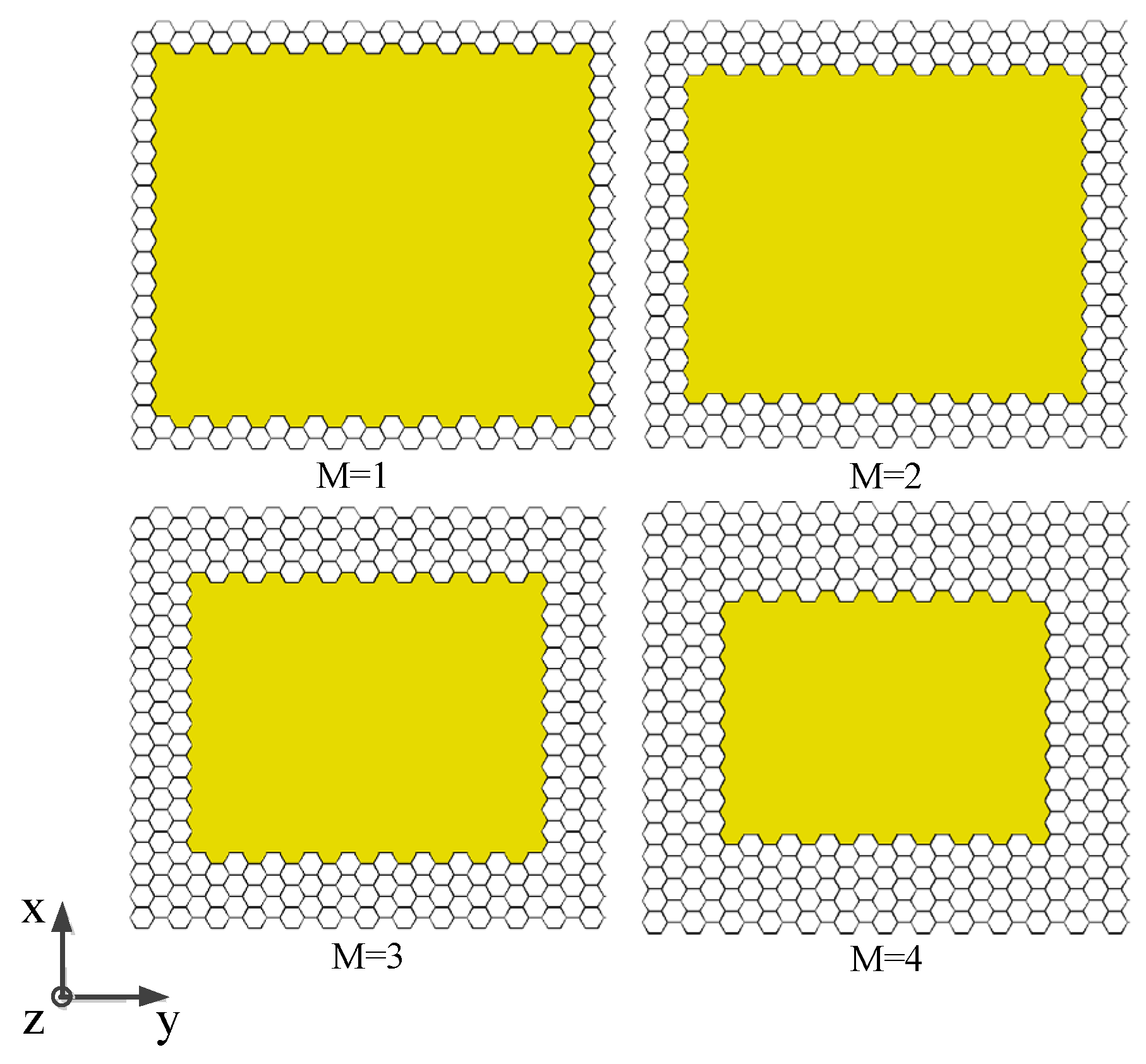
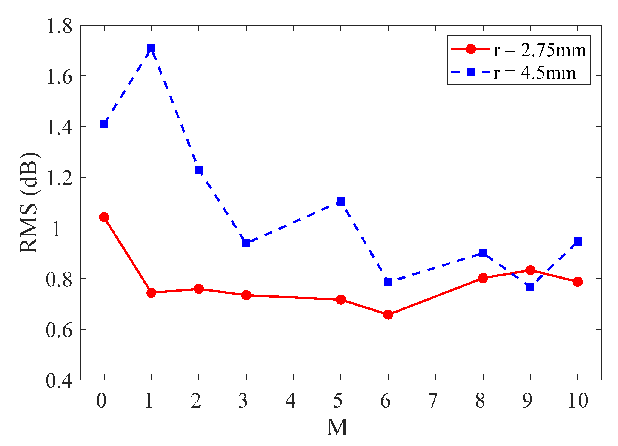
Drawing on antenna array analysis methods, we use the minimum number of unit cells in the RSBC subregion along the x and y directions, noted as M, to describe the size of the RSBC subregion, as shown in
Figure 5. Obviously, the larger M, the larger the RSBC region used and vice versa. When M is set to 0, the proposed hybrid approach is in fact reduced to the conventional homogenization method, while when M is set to be large enough, it is reduced to the conventional RSBC method. We first set the aperture size of the unit cell to
2.75 mm and 4.5 mm. The RMSs of the computed results for the honeycomb panel with a varying number of
M at 8 GHz are plotted in
Figure 6. As can be seen in the figure, when
M increases, the RMS becomes smaller. When M is larger than 6 for both
2.75 mm and 4.5 mm, results with the RMS smaller than 1 dB can be obtained. According to our numerical experience, an RMS no greater than 1 dB well ensures the agreement between the two considered results. Therefore, it is necessary to determine a suitable M value that can ensure both calculation accuracy and a high efficiency. Through this numerical experiment and our numerical experience, we should set
to ensure a good accuracy and a high efficiency.
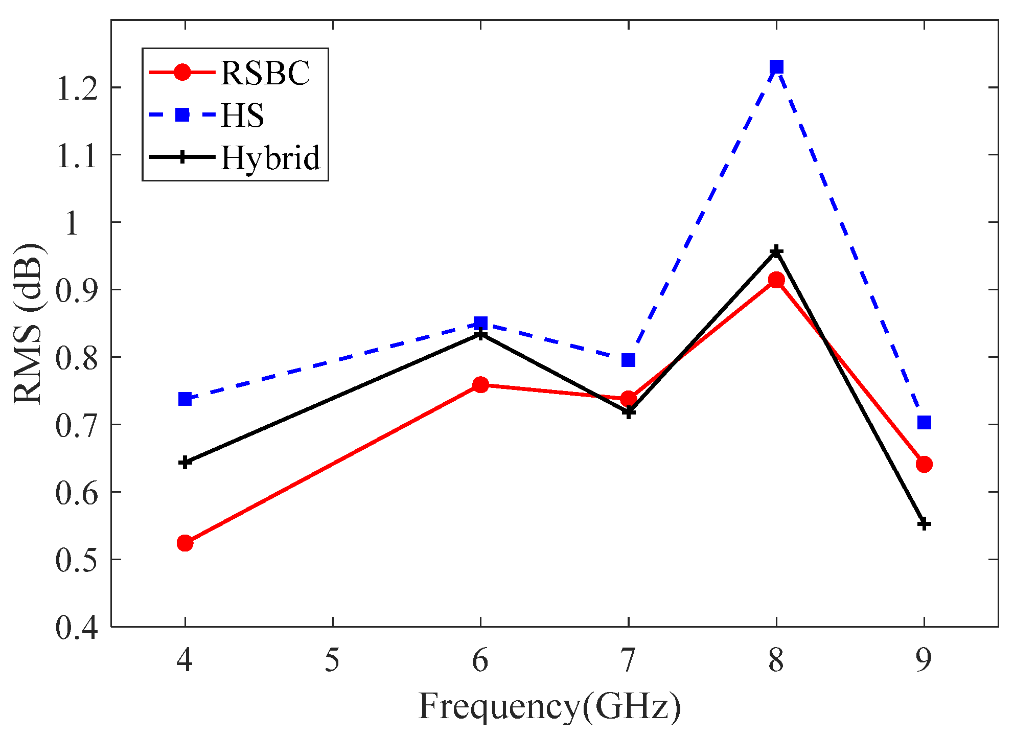
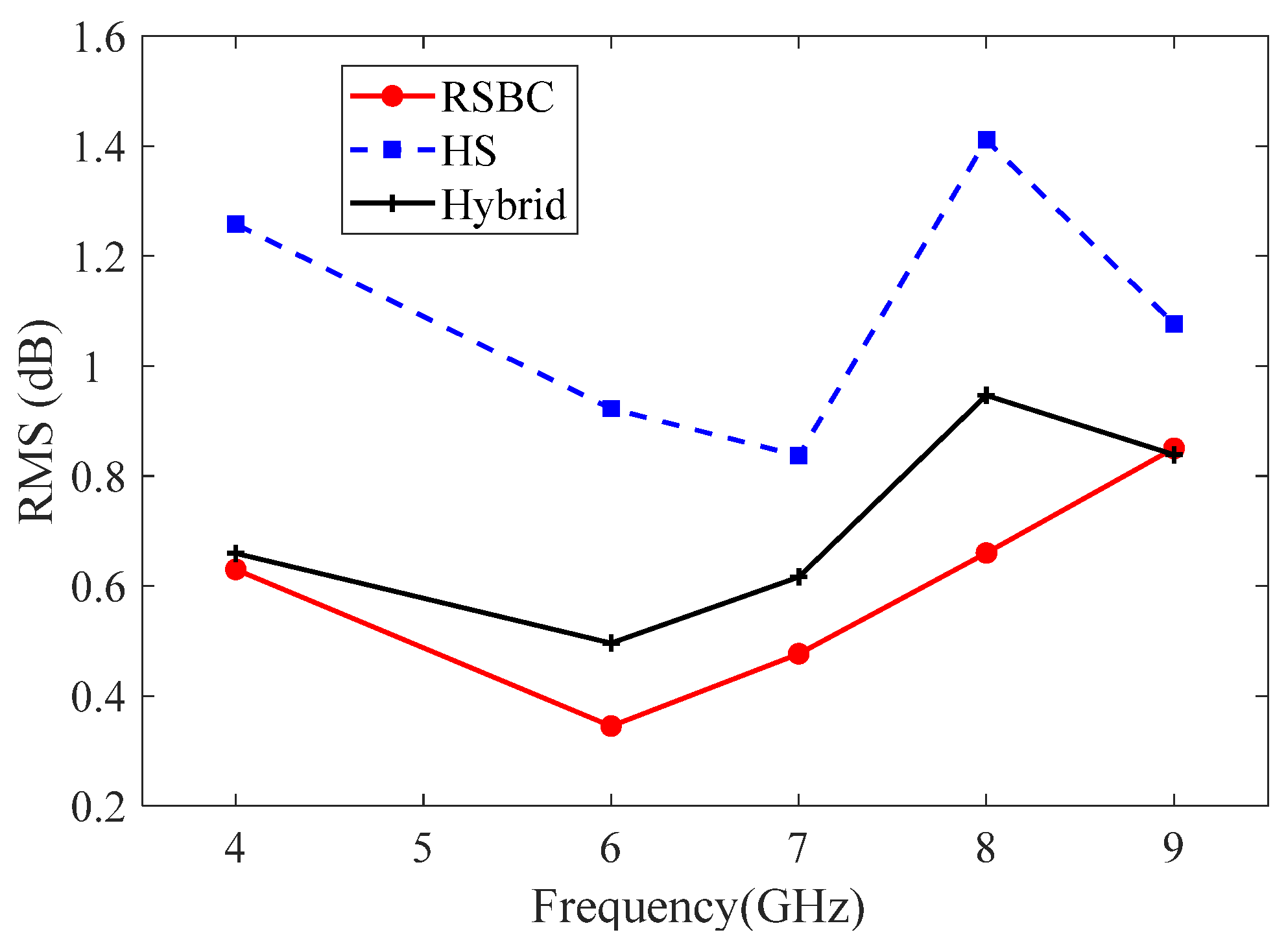
Then, we study the influence of the operating frequency when the value of M is fixed to 6.
Figure 7 and
Figure 8 show the RMSs as a function of frequency for the panel models with aperture sizes r = 2.75 mm and 4.5 mm. The results obtained by using the HS homogenization and RSBC methods are also given in the figures as a comparison. As shown in those figures, the proposed method (noted as Hybrid) exhibits a higher accuracy than the HS homogenization, and the RMSs are smaller than 1 dB when the frequency increases from 4 GHz to 9 GHz for both r = 2.75 mm and r = 4.5 mm. For example, when the aperture size is set to 4.5 mm, the RMS of the HS homogenization method is greater than 1 dB, except for at 6 GHz and 7 GHz. In contrast, although the accuracy of the hybrid method is a bit lower than that of the RSBC method, the RMS remains smaller than 1 dB, proving that the proposed hybrid method can ensure a good accuracy for honeycomb structures of different sizes over a wide range of operating frequencies.
Next, we demonstrate the efficiency and accuracy of the proposed hybrid approach for complicated honeycomb composites. In all the following examples, the relative permittivity of the honeycomb core is set to , and the wall thickness and the radius of the unit cell is set to 0.05 mm and 4.5 mm, respectively.
The first example is a widely used sandwich panel consisting of a honeycomb core and dielectric skins, as illustrated in
Figure 9. The relative permittivity for dielectric skins is set as 3.8. For the hybrid method model, the effective permittivity of the inner region of the honeycomb structure is derived as
and
using the H-S and the M-T formulae proposed in [
22]. The number M of unit cells in the outer subregion is set as 6. We compute the VV-polarized monostatic RCS of the plate with the incident plane wave set at 8 GHz with the incident angle set as
. The results obtained by using the proposed hybrid method (noted as Hybrid) are given in
Figure 10, together with those obtained using the MoM of FEKO and the HS homogenization approach. Compared with the conventional homogenization theory, the proposed hybrid approach exhibits a higher accuracy, especially when the incident angle of the axis of the honeycomb unit cell is large.
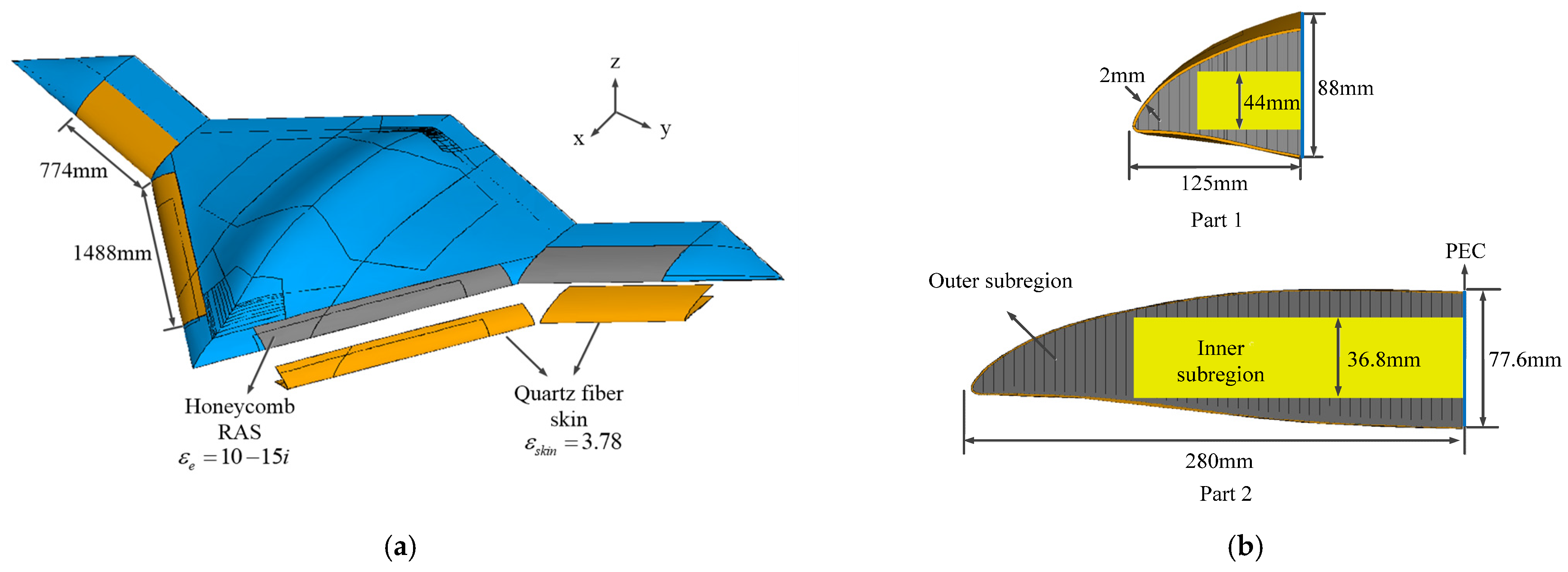
The second example is a wing-like object. It has a length of 620 mm, a width of 560 mm, and a height of 90 mm. It consists of a quartz glass fiber skin with a relative permittivity of 3.78, a radar-absorbing honeycomb core, and a PEC frame. The upper and lower surfaces of the wing are covered with quartz glass fiber skins, as illustrated in
Figure 11. We compute the bistatic RCS of the wing-like object at 4.5 GHz with the incident angle
. The observation plane is in the xy plane. The computed VV-polarized bistatic RCS obtained using the proposed method, the RSBC method, and the HS homogenization method is shown in
Figure 12. If we choose the RSBC results as the reference data, an overall better agreement is observed for the proposed hybrid approach, especially with the angle ranging from 68 to 90 degrees, when compared with the HS homogenization approach. From this example, we can demonstrate that the hybrid approach has a higher accuracy than the conventional HS homogenization approach.
Finally, an unmanned aerial vehicle (UAV) model with microwave-absorbing honeycomb structures is simulated, and it has a length of 2.68 m with a wingspan of 4.73 m, as shown in
Figure 13a. The leading edges of the fuselage and wings are made of honeycomb radar-absorbing structures covered with a quartz glass fiber skin. The quartz glass fiber skin is supposed to have a thickness of 2 mm and
= 3.8. The geometry details are shown in
Figure 13b. The UVA model is illuminated by a plane wave at 6 GHz with the incident angle set as
. The observation plane is defined in the xy plane. The VV-polarized bistatic RCSs obtained using the proposed method, together with those obtained using the RSBC approach, are plotted as a function of the bistatic angles, as shown in
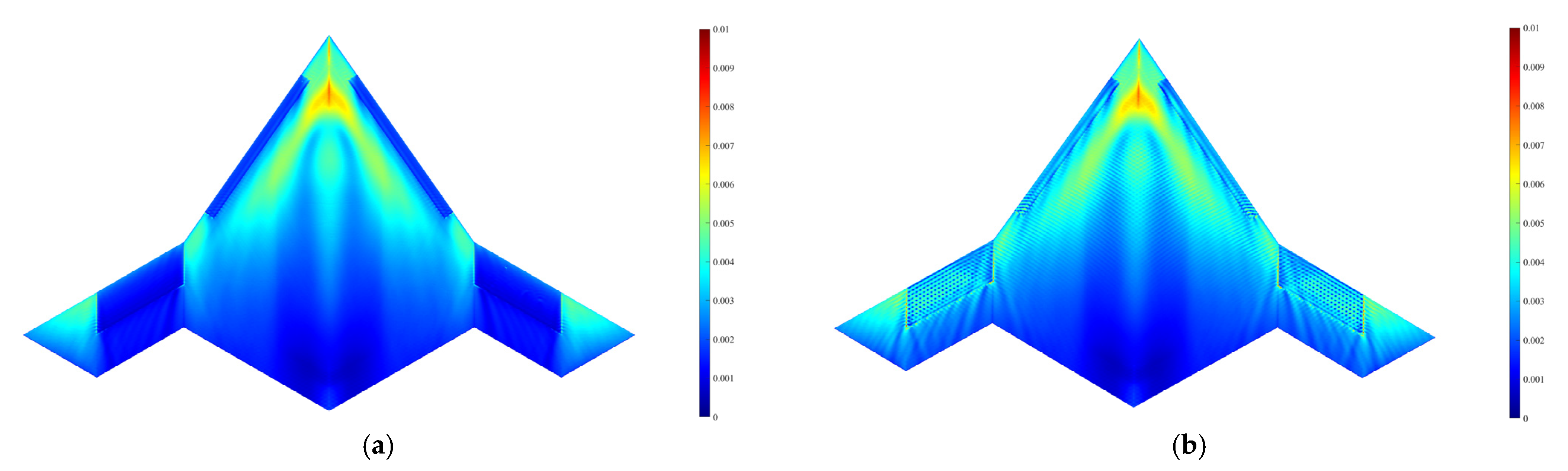
Figure 14. We can see in the figure that they are in good agreement. Compared with the case without the honeycomb RAS, significant RCS reductions are observed, showing the effectiveness of the honeycomb structures for microwave absorption. We also plot in
Figure 15 the electric current distributions on the surface of the UVA model with and without honeycomb structures. As can be seen in the figure, the surface currents on these parts with the honeycomb RAS are obviously weaker. The computational resources are listed in
Table 1. As can be seen in this table, with the proposed approach, the total FEM unknowns are reduced by about 33%, while the memory and the CPU time are reduced by about 22% and 29%, respectively, showing the significant efficiency improvement of the hybrid method over the conventional RSBC method.


