Abstract
As a new type of magnetic levitation train with the characteristics of self-stabilization and self-suspension, high-temperature superconducting magnetic levitation has developed to the test line research stage. In order to promote the rapid development of high-temperature superconducting magnetic levitation train engineering, and the main electromagnetic radiation sources are clarified by analyzing their working principles and structures. Then Ansoft Maxwell EM was used to build a 3D magnetic levitation train electromagnetic environment simulation model to simulate and predict the electromagnetic radiation characteristics of the magnetic levitation train system. Finally, a field EMF test was carried out to verify and assess the impact on the EM environment in the system. The results show that the permanent magnet track on the ground and the synchronous linear motor are the primary electromagnetic radiation sources, and the generated fields are mainly low-frequency fields and static magnetic fields. The low-frequency magnetic field inside the train decreases with the increase of frequency and is partially shielded by the carriage; The static magnetic field cannot be weakened by the carriage, and the static magnetic field inside the car decreases with the increase of height. All types of electromagnetic fields are far below the requirements of the relevant electromagnetic environmental standard limits, and have no effect on the electromagnetic radiation safety of the personnel inside the train and the surrounding environment; In considering of the special people who have pacemakers, static magnetic field suppression measures are studied, and the results show that the trains with high magnetic permeability permalloy as the shielding layer at the bottom of the vehicle greatly lower the static magnetic field within the train.
1. Introduction
People’s demand for transportation system speed is getting higher and higher, but the traditional high-speed train using a wheel-track method is limited by various restrictions, such as traveling resistance and pantograph offline, so it is difficult to break through the existing speed limit. In order to achieve a faster running speed, other technologies are needed to realize the guidance and traction of the train, and also to avoid using a pantograph for the power supply. High-temperature superconducting magnetic trains have begun to be deployed in the rail transportation industry as a new rail transportation mode [1,2,3]. The first high-temperature superconducting high-speed magnetic levitation prototype and test line have been built at Southwest Jiaotong University. Synchronous linear motors are used in the high-temperature superconducting maglev, and traction is provided by an interaction between the mover’s magnetic field and the traveling wave magnetic field produced by the ground stator. The high-temperature superconducting material and the “flux-pinning effect” of permanent magnets are used to achieve guidance and levitation. Both the guiding and levitation systems of high-temperature superconducting magnetic levitation generate magnetic fields that partially leak. These fields may affect the human body and the magnetic levitation system equipment, which urgently need to be studied for their electromagnetic environment.
With the rapid development of maglev train technology, its leaking electromagnetic fields have also raised concerns about the possible health risks to residents along the line, and studies on its electromagnetic environment have gradually begun. Jianqing WANG and Osamu FUJIWARA [4,5] from the Nagoya Institute of Technology, Japan, and others have tested and evaluated the EMF environment around the Tobu Kyuryo Maglev train line in Japan, and the results showed that the EMF of the Tobu Kyuryo line fully complied with the international safety guidelines, and even under the worst-case scenario when accelerated to the maximum speed, the AC magnetic field level was still half of the ICNIRP reference level. Yumei Du et al. [6] used the two-dimensional finite element method (FEM) to calculate the leakage magnetic field around the levitating electromagnet and linear induction motor under different operating conditions of the Tangshan low-and medium-speed maglev experimental line and to measure the ambient electromagnetic field of the experimental line. The analysis and measurement results show that the maximum leakage flux density generated by the levitating electromagnet and the linear induction motor is in accordance with international safety guidelines. Shen et al. [7] tested the external radiation of a low- and medium-speed maglev in China and ascertained that its external radiation is much lower than the limit value specified in the standard. Li Tianshi et al. [8] compared the measured electromagnetic radiation data of the Changsha low- and medium-speed maglev transportation system with that of a conventional wheeled rail system and derived their differences in terms of DC magnetic field, low-frequency magnetic field, and RF electromagnetic field between them, which provide the basis for relevant electromagnetic compatibility standards and the electromagnetic protection design of trains. Kai Yu [9,10] comprehensively analyzed the electromagnetic radiation of low- and medium-speed maglev trains from a theoretical point of view, including the DC steady-state fields, low-frequency AC fields, and arc high-frequency fields. Shi Xinyang and Liu Jingcheng [11] measured the external electromagnetic radiation of maglev trains under acceleration climbing and high-speed driving conditions by using a sensor method and an antenna method; they also conducted an electromagnetic environment assessment according to IEEE-STD-C95.1-2005, IEEEStd-C95.6-2002, ICNIRP-2010, and GB8702-2014, and the assessment The results show that it is far below the relevant electromagnetic environment limits. In summary, the electromagnetic field generated by maglev trains mainly comes from linear motors and levitation electromagnets, and the most influential are the low-frequency magnetic field and static magnetic field. At present, the research on the electromagnetic environment of maglev trains mainly focuses on field electromagnetic environmental testing, and the research on the electromagnetic environment of high-temperature superconducting maglev trains has not been reported.
Considering that the field electromagnetic environment test can only be conducted after the train is completed, it is difficult to obtain the electromagnetic radiation characteristics of the magnetic levitation train at the train design stage. In this paper, based on the high-temperature superconducting magnetic levitation engineering prototype and test line, the magnetic field distribution of the high-temperature superconducting magnetic levitation test line train is studied by establishing a finite element electromagnetic environment prediction model, and the correctness of the electromagnetic environment prediction model is verified by combining a static magnetic field test and AC magnetic field test; thus, the electromagnetic radiation of the train is evaluated. The analysis and prediction of electromagnetic radiation emission characteristics in the pre-design stage promote the rapid development of high-temperature superconducting magnetic levitation train engineering, and provide direction and basis for the design of the electromagnetic protection of magnetic levitation trains.
2. Analysis of the Working Principle and Structure of High-Temperature Superconducting Magnetic Levitation
2.1. Analysis of the Working Principle
High-temperature superconducting magnetic levitation train levitation and guidance are achieved by the interaction between the vehicle’s high-temperature superconductors and the permanent magnets on the ground, i.e., the “flux-pinning effect.” The high temperature of high-temperature superconductors is relative to low-temperature superconductors, with cooling temperatures of −196 °C and −269 °C, respectively. The unique pegging characteristics of high-temperature superconductors and their own defects create pegging centers that make it difficult for bound magnetic lines to escape and for inaccessible magnetic lines to enter the interior of the superconductor. The external magnetic field changes and the high temperature superconductor generates a strong superconducting current that hinders the change of magnetic lines of force and forms a magnetic field inside the superconductor, which interacts with the direction of the magnetic field generated by the magnet to generate the force that keeps the train suspended and guided. The traction system uses a synchronous linear motor with a ground-based three-phase AC coil as the stator, a vehicle-based permanent magnet as the mover, and an air gap between the stator and the mover. In the air gap, the ground stator winding passes into the three-phase current to produce the traveling wave magnetic field and the magnetic field of the permanent magnet mover, interacting with each other to generate the traction force to push the train forward.
2.2. System Structure of the High-Temperature Superconducting Magnetic Levitation Train
The high-temperature superconducting magnetic levitation train system mainly consists of a permanent magnet track system on the ground, a synchronous linear motor system, a vehicle-based high-temperature superconductor and low-temperature cooling system, and the train; the structure is shown in Figure 1. The permanent magnet track uses a Halbach structure [12,13] laid along the track; the magnetization direction is shown in Figure 2. This magnetization method produces a wider and stronger magnetic field, providing a stronger levitation force. The stator of the synchronous linear motor system adopts a three-phase AC motor, and the vehicle mover adopts NdFe_3O permanent magnets (an intermetallic compound-based permanent magnet material with the main components of neodymium Nd, iron Fe, and boron B) or excitation magnets, and the traveling wave magnetic field generated by the three-phase AC motor interacts with the vehicle magnets to generate traction. The vehicle’s high-temperature superconductor adopts YBaCuO material and uses liquid nitrogen for cooling to achieve a superconducting state.
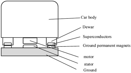
Figure 1.
Structure of high-temperature superconducting magnetic levitation system.
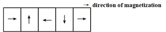
Figure 2.
Cross-section of Halbach permanent magnet on the ground.
2.3. Analysis of Electromagnetic Interference Sources
Based on the analysis of the working principle and structure of high-temperature superconducting magnetic levitation, the potential electromagnetic interference sources are the linear motor and the ground-based permanent magnet orbit. The linear motor air gap is open, which may generate leakage flux. The magnetic field of the permanent magnet track acts with the high-temperature superconductor to form the guiding and levitation force; the linear motor mover and the permanent magnet track are the static magnetic field emission sources, and the linear motor stator winding is the AC magnetic field emission source.
3. Electromagnetic Simulation Model Building and Results Analysis
3.1. Simulation Model Building
In order to analyze the electromagnetic environment of the magnetic levitation train system, a 3D electromagnetic simulation model was built in Maxwell software according to the actual structure of the high-temperature superconducting high-speed magnetic levitation prototype test line (as shown in Figure 3) and the working principle analysis, and the structure was modeled according to a 1:1 ratio, including the body, bracket, ground permanent magnet track, linear motor, and superconductor. The material parameters, simulation excitation, boundary conditions, solution frequency, and background conditions are also set. The height of the prototype train is 2.5 m; the width is 3.2 m; the length is 20.05 m; and the suspension height of the train is 10 mm. The total length of the track is 25.86 m.
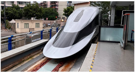
Figure 3.
Actual structure of the test line.
The main material used in the body of the high-temperature superconducting magnetic levitation train is mainly aluminum alloy. Although the models of various aluminum alloy materials are different in different regions, their electrical conductivity and relative permittivity are basically the same, and the body can be modeled in the same aluminum alloy material with the thickness set to 10 mm. The maglev train body is connected to the linear electric motor and superconducting levitation module by an iron support. The permanent magnet track on the ground is of the Halbach type as described above. The linear synchronous motor ground stator operating frequency is 0–150 Hz; the rated current is 600 A, and the material is copper. Maxwell 3D uses tetrahedral mesh dissection, and the number of meshes depends on the size of the computational domain and the density of the mesh. Due to the large computational domain and the large number of meshes in this model, a large amount of computer memory resources is required, and the simulation speed and solution accuracy are taken into account. The specific material parameters and model parameters are shown in Table 1 and Table 2. The established electromagnetic environment model of the high-temperature superconducting magnetic levitation train is shown in Figure 4.

Table 1.
Model material settings.
Table 2.
EM simulation model parameter values.
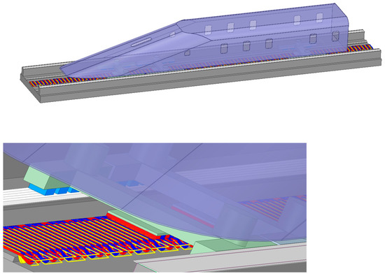
Figure 4.
Simulation model of electromagnetic environment of magnetic levitation train.
3.2. Low Frequency Fundamental Magnetic Field Emission
The low-frequency fundamental magnetic field source is the linear motor stator winding generating fundamental currents at 0–150 Hz during the operation of the maglev train, i.e., the fundamental magnetic field range is 0–150 Hz. The three-dimensional eddy current field solver of Maxwell software is used to analyze and simulate the magnetic field emission distribution at different frequencies. The maximum current value of this test line is 600 A, and the magnetic field distribution at different frequencies is shown in Figure 5. Frequencies at 5 Hz, 50 Hz and 150 Hz are selected, corresponding to the low, medium, and high speed of the train.
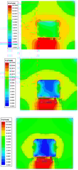
Figure 5.
Field magnetic distribution at 5 Hz, 50 Hz, 150 Hz frequency.
As seen from the simulation results, the magnetic field distribution pattern at different frequencies is basically the same, emitted outward from the linear motor and concentrated in the lower part of the train body. The magnetic field distributed along the physical center of the train is not completely symmetrical due to the linear motor end effect, and the electromagnetic emission in the carriage decreases with the increase of frequency. In order to better quantify the magnitude of the magnetic field, this paper selects nine sampling points at typical cross-sections of 0.3 m, 0.9 m, and 1.5 m from the bottom of the train train, respectively, based on the standard TB/T 3351-2014 standard requirements, three heights of 0.3 m, 0.9 m and 1.5 m from the ground were selected, and the sampling was carried out at 0.3 m from both ends of the train and the center of the axle, as shown in Figure 6. The values of magnetic induction at the nine points with different frequencies are shown in Table 3.
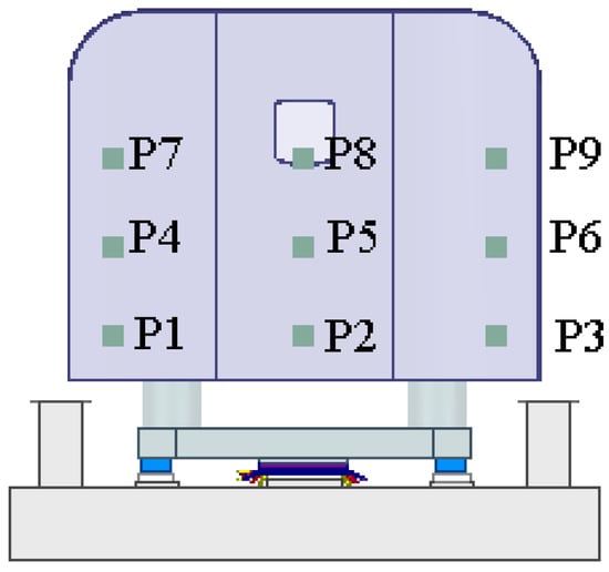
Figure 6.
Sampling points location.
Table 3.
Magnetic induction intensity values at different frequencies.
It can be seen that when the train is running at low speed, the magnetic field strength decreases with the increase of height. When the train is running at medium or high speed, the magnetic field strength of P4, P6, P7, and P9, located at the window side of the train, is much stronger than that of the internal area of the vehicle, that is, the magnetic levitation body can shield most of the magnetic field of this frequency. At this time, the low frequency magnetic field mainly comes from the leakage of the window. According to the requirements of relevant electromagnetic compatibility standards for electromagnetic environments to analyze the magnetic field, TB/T 3351-2014 stipulates the limits of public exposure to the time-varying magnetic field at a distance of 0.3 m, 0.9 m, and 1.5 m from the floor height of the rolling stock, and a comparison with the simulation results shows that the magnetic induction strength at all frequencies is much lower than the limits of the electromagnetic environment standards.
3.3. Static Magnetic Field Emission
The sources of static magnetic field simulation are the permanent magnet track and the linear electric motor, and the three-dimensional static magnetic field solver of the Maxwell software 2021 is used to analyze the static magnetic field distribution of the train as a whole, as shown in Figure 7. It can be seen that the static magnetic field is mainly distributed in the lower part of the maglev train, symmetrically distributed on the vertical centerline of the train. The train body has almost no shielding effect on the static magnetic field. The static magnetic field decays rapidly with the increase of distance. The static magnetic field around the permanent magnet track and linear motor winding is much greater than the static magnetic field inside the train, and the magnetic field at the bottom of the maglev train train is also greater.
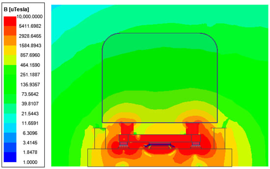
Figure 7.
Static magnetic field distribution of magnetic levitation train.
In order to protect passengers and staff in the passenger compartment of the rolling stock from electromagnetic hazards and interference, relevant electromagnetic compatibility standards are specified to control the electromagnetic fields generated by the rolling stock, to which magnetic levitation trains can be referred to. The standard of static magnetic field limit is the International Commission on Non-Ionizing Radiation Protection (ICNIRP) guidelines (2010) [14] with TB/T 3351-2014. Sampling points are set inside the train body, which are consistent with the sampling points during the low-frequency magnetic field analysis, and the magnetic induction intensity of nine sampling points are shown in Table 4. It can be seen that the static magnetic field magnetic induction intensity decreases significantly with the increase of height, and the magnetic induction intensity at the same height is closer.
Table 4.
Static magnetic field values at sampling points.
Comparing the static magnetic field value at the sampling point with the (ICNIRP) guideline (2010) limit requirement, it can be found that the static magnetic field is much lower than the ICNIRP public exposure limit, and it can be concluded that the static magnetic emission from this high-temperature superconducting test line will not cause adverse health effects to the personnel in the magnetic levitation train system.
3.4. Study of Static Magnetic Field Suppression Measures
The electromagnetic field obtained from the simulation has met the general passenger electromagnetic environment standard requirements, but considering the population with special medical needs, such as people with pacemakers, the standard EN45502-2 [15] is also considered, which stipulates that the static magnetic field value inside the rolling stock should not be higher than 1 mT to avoid interference with the normal operation of pacemakers. In order to ensure the safety of special populations in the maglev train environment and to provide guidance for subsequent electromagnetic protection, we investigate static magnetic field suppression measures.
The static magnetic field of maglev trains is suppressed by using high permeability materials as shielding plates. The high permeability material is made of permalloy, which has the advantages of high magnetic permeability and high saturation magnetic induction strength [16] and can effectively shield the static magnetic field. Its relative magnetic permeability is taken as 2 × 10⁴ S/m with electrical permeability 5 × 10⁷ S/m. The shielding layer is located at the bottom of the maglev train carriage, and the thickness of the shielding layer is 10 mm. The static magnetic field distribution after the shielding is obtained by simulation is shown in Figure 8, and it can be seen that the static magnetic field is obviously partly isolated after adding the shielding plate. In order to quantitatively observe the change value of the magnetic field before and after shielding, the magnetic field of the above nine points is sampled, and the values before and after shielding are shown in Table 5. It can be seen that the double shielding panel obviously reduces the static magnetic field inside the carriage.
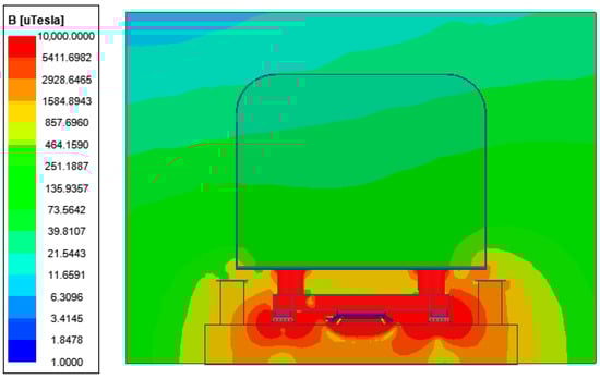
Figure 8.
Static magnetic field distribution after shielding.
Table 5.
Magnetic induction intensity values before and after shielding.
4. High-Temperature Superconducting Magnetic Levitation System Electromagnetic Environment Testing
In order to verify the electromagnetic emission characteristics of the high-temperature superconducting magnetic levitation system, this paper conducted electromagnetic environment tests on the test line. Since the length of the test line is 165 m and the test condition is low-speed (30 km/h) operation. At this time, except for the lighting and display system, no other on-board systems are operating. The test site diagram is shown in Figure 9.
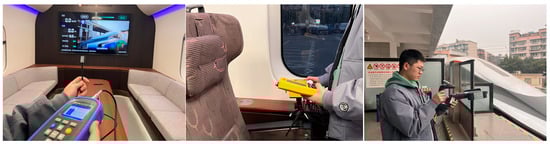
Figure 9.
High-temperature superconducting maglev train electromagnetic environment test site.
4.1. Static Magnetic Field Test
The static magnetic field in the train is tested at the slow speed of the train. The test position is as above, and the static magnetic field test values are shown in Table 6.
Table 6.
Static magnetic field test values.
As can be seen from the table, the magnetic field at the bottom of the train train is greater, and the static magnetic field decreases with the increase of height. The measured results are basically consistent with the simulation results of the electromagnetic environment, and the magnetic field value is much lower than the requirement of (ICNIRP) guideline limit value.
4.2. AC Electromagnetic Field Testing
4.2.1. Low Frequency Electromagnetic Field Testing
The low-frequency electromagnetic field test was measured using an electromagnetic radiation analyzer [17,18,19,20] with a test frequency of 0–150 kHz and test point locations as described above. Figure 10 shows the curve of the low-frequency magnetic field with frequency in the 0.3 m plane at the bottom of the carriage when the maglev train is running at low speed, showing that the low-frequency magnetic field is concentrated at the 0–8 Hz range during the test, probably because the linear motor was operating at 0–8 Hz at this time. Table 7 shows the magnetic field values at the sampling location when the frequency is 5 Hz.
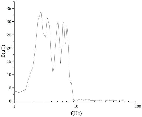
Figure 10.
Low frequency magnetic field test spectrum.
Table 7.
5 Hz magnetic field test values in low-speed operation.
It can be seen from Table 6 that the magnetic field strength decreases with increasing height when the train is running at low speed and is much lower than the limit requirement, and the trend is basically consistent with the simulation results when compared with the 5 Hz results (Table 2) during the electromagnetic environment simulation. The simulation successfully predicts the magnetic field distribution at low speed. Due to the limitation of the test line length, the magnetic field distribution at medium speed and high speed of the maglev train can be referred to the EM simulation results. In order to clarify further low-frequency electromagnetic interference sources, the stator winding current of the linear motor under low-speed operation was tested, and the results are shown in Figure 11. The stator winding current spectrum is exactly the same as the low-frequency magnetic field spectrum in the environment, that is, the stator winding is the main source of low-frequency electromagnetic interference.
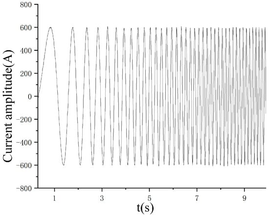
Figure 11.
Stator winding current.
4.2.2. High Frequency Electromagnetic Field Testing
The high-frequency field test is conducted outside the vehicle to measure the high-frequency electromagnetic radiation to the outside of the vehicle, and the test uses the antenna method with a test frequency of 150 kHz–6 GHz. First, the background electromagnetic field of the maglev train without high-temperature superconductivity is tested when the train passes through, and then the electromagnetic field of the maglev train is tested when it passes through. The maglev train in motion is equivalent to the radiation source, and the test points are arranged along the extension of two orthogonal lines from the center of the radiation source at a distance of 5 m. The curves of the background electric field and the electric field value of the maglev train operation are shown in Figure 12.
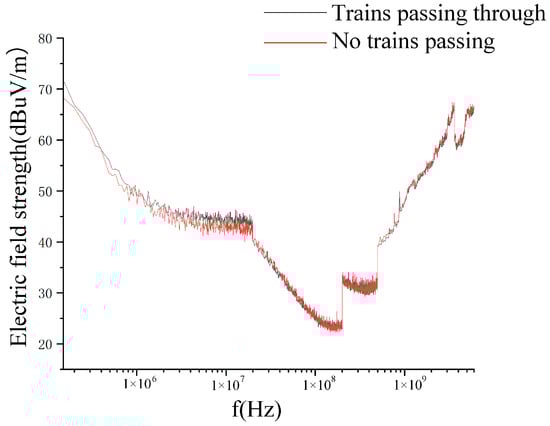
Figure 12.
High frequency electromagnetic field test values.
As can be seen from Figure 12, the measured EMF value curves with and without high-temperature superconducting magnetic levitation trains passing through basically overlap, all below 70 dBuV/m, which are all background noise, far below the relevant standards, i.e., the high-temperature magnetic levitation train system almost does not produce external high-frequency electromagnetic radiation at static or low speed.
5. Conclusions
In this paper, through the analysis of the working principle and structure of the high-temperature superconducting magnetic levitation train, a finite element electromagnetic simulation model is established based on the high-temperature superconducting magnetic levitation test line, and the electromagnetic radiation characteristics of the magnetic levitation train are predicted and analyzed. The correctness of the electromagnetic environment prediction model is verified by combining the static magnetic field test and the AC magnetic field test. Simulation and test results show that the electromagnetic field generated by the high-temperature superconducting magnetic levitation system is a composite space field, mainly including a static magnetic field and a low-frequency field, and the electromagnetic field of each frequency meets the requirements of the relevant limits, which shows they have no effect on the electromagnetic radiation safety of the vehicle occupants and the surrounding environment.
Author Contributions
Software, Q.W. and X.L.; methodology, H.Z. and J.Z.; resources, Z.D. and W.Z.; writing—review and editing, X.T. All authors have read and agreed to the published version of the manuscript.
Funding
This research was funded by The Fundamental Research Operation Funds of the Central Universities of China, grant number 2682021ZTPY128, 2682021ZT039 and Key R&D Project of Sichuan Science and Technology Department, grant number 22ZDYF3091.
Data Availability Statement
The data presented in this study are available on request from the corresponding author. The data are not publicly available due to the data also forms part of an ongoing study.
Conflicts of Interest
The funders had no role in the design of the study; in the collection, analyses, or interpretation of data; in the writing of the manuscript; or in the decision to publish the results.
References
- Wang, J.; Wang, S. High Temperature Superconducting Maglev Train. J. Electr. Eng. 2015, 10, 1–10. [Google Scholar]
- Xiong, J.; Deng, Z. Research progress of high-speed maglev rail transit. J. Traffic Transp. 2021, 21, 177–198. [Google Scholar]
- Ma, G.; Yang, W.; Wang, Z.; Ye, C.; Li, J. Research Development of Superconducting Maglev Transportation. J. South China Univ. Technol. (Nat. Sci. Ed.) 2019, 47, 68–74, 82. [Google Scholar]
- Fujiwara, O.; Wang, J.Q.; Ishimoto, S.; Fujino, M.; Mizuma, T. Environment Impact Assessment on the Tobu-Kyuryo-Line(HSST system) in Japan. In Proceedings of the Maglev, Shanghai, China; 2004; pp. 632–635. [Google Scholar]
- Wang, J.Q.; Fujiwara, O.; Ishimoto, S.; Fujino, M.; Mizuma, T. Electromagnetic environment assessment for the Tobu-Kyuryo-Line (HSST System) in Japan. In Proceedings of the 18th International Conference on Magnetically Levitated Systems and Linear Drives Maglev, Shanghai, China, 26–28 October 2004; pp. 636–639. [Google Scholar]
- Du, Y.; Han, J.; Zhang, R.; Jin, N.; Sun, G. Leakage Field Analysis of Levitation Electromagnet and Driving Motor for Medium and Low Speed Maglev 'Trains. In Proceedings of the International Conference on Electrical Machines and Systems, Incheon, Republic of Korea, 10–13 October 2010; pp. 1903–1906. [Google Scholar]
- Shen, G.Q.; Zheng, D.; Wang, Y.B. Simulation and Verification of Electromagnetic Radiation for the Moving Maglev Train. Environ. Technol. 2020, 38, 112–118. [Google Scholar]
- Li, T.; Gong, M.R.; Huang, H.; Su, L. Difference Analysis of Electromagnetic Environment Effects between Wheel-rail Transit and High-speed Surface Transport. Railw. Signal. Commun. 2021, 57, 53–57. [Google Scholar]
- Yu, K. Research on the Principle of Electromagnetic Radiation in Low and Medium Speed Maglev Traffic. J. Railw. Eng. Soc. 2020, 37, 74–79. [Google Scholar]
- Yu, K.; Yu, C.; Wei, B.; Duan, Y.Q. Research on the Electromagnetic Safety Protection Distance between Medium and Low Speed Maglev Traffic and Railway. J. Railw. Eng. Soc. 2020, 37, 95–99. [Google Scholar]
- Shi, X.; Liu, J. Actual Measurement and Evaluation of Electromagnetic Environment for the Moving Maglev Train. In Proceedings of the 13th International Conference on Microwave and Millimeter Wave Technology, Bangkok, Thailand, 24–26 April 2020. [Google Scholar]
- Li, G.; Lu, M.; Li, J. Safety assessment of passengers in electromagnetic exposure to magnetic field on superconducting magnetic levitation track. Mod. Electron. Tech. 2022, 45, 12–118. [Google Scholar]
- Zhang, M.; Li, M.; Liu, P.; Yan, Y.; Liu, L.; Yang, X. Study on Levitation Characteristics of High Temperature Superconducting Pinned Maglev Train. China Mech. Eng. 2022, 33, 2764–2771. [Google Scholar]
- ICNIRP. Guidelines for limiting exposure to time-varying electric and magnetic fields (1 Hz to 100 kHz). Health Phys. 2010, 99, 818–836. [Google Scholar] [CrossRef] [PubMed]
- DIN EN 45502-2-1-2004. Active Implantable Medical Devices, Part 2-1: Particular Requirements for Active Implantable Medical Devices Intended to Treat Bradyarrhythmia (Cardiac Pacemakers); European Standards Institute: Sophia-Antipolis, France, 2004.
- Wu, Y.; Sheng, W.; Han, Y.; Ma, X.; Zhang, R. The simulation and testing analysis on low-frequency magnetic shielding effectiveness of metal materials. Chin. J. Radio Sci. 2015, 30, 673–678. [Google Scholar]
- Tian, R.; Lu, M. Simulation and Health Assessment of Low Frequency Electromagnetic Exposure of Power Cables Below the Carriage of High-speed Electric Multiple Units. High Volt. Eng. 2016, 42, 2540–2548. [Google Scholar]
- Fu, C.; Zhao, T. Research on low-frequency magnetic field testing technology for urban rail vehicles. Electron. Technol. Softw. Eng. 2021, 5, 100–102. [Google Scholar]
- Zhu, F.; Niu, D.P.; Xu, C.W. Measurement and analysis on ambient magnetic field inside the bodywork of CRH1. J. Electr. Power Sci. Technol. 2012, 27, 42–46. [Google Scholar]
- Luo, R.; Wu, J.; Li, Z. Research on Electromagnetic Interference of Space which Suspension Sensor of Medium-Low Speed Maglev Train Located. Instrum. Tech. Sens. 2018, 11, 1–6. [Google Scholar]
Disclaimer/Publisher’s Note: The statements, opinions and data contained in all publications are solely those of the individual author(s) and contributor(s) and not of MDPI and/or the editor(s). MDPI and/or the editor(s) disclaim responsibility for any injury to people or property resulting from any ideas, methods, instructions or products referred to in the content. |
© 2023 by the authors. Licensee MDPI, Basel, Switzerland. This article is an open access article distributed under the terms and conditions of the Creative Commons Attribution (CC BY) license (https://creativecommons.org/licenses/by/4.0/).