1. Introduction
To take advantage of size and achieve a high spectral efficiency of antennas, communication systems have recently undergone a new development based on simultaneous transmission and reception. In radar and 5G applications, an antenna’s main lobe beamwidth determines the system’s angular resolution as it produces the required directivity for good angular resolution. The antenna gain, on the other hand, has a significant impact on the detection range of the system. As a result, an antenna array is the best candidate for achieving these goals. The sharing of electronic and antenna components in a monostatic configuration reduces the size and cost of synchronization between the transmitter and receiver, which is why the vast majority of radars are monostatic [
1]. As a result, on a single platform, a coupling challenge exists between the transmitting and receiving antennas. For the reason that coupling causes a correlation between the transmitting and receiving paths, it must be suppressed in order for these two functions to operate independently. If coupling is not suppressed, the receiver may experience saturation and intermodulation [
2].
A microstrip patch antenna, even though it is a high-gain planar antenna, is preferred for many portable radars and 5G applications because of its low cost and low profile. It can be fixed by employing arrays with configurations determined by the desired antenna characteristics. A microstrip antenna produces inter-coupling between its component constructions on the same platform, with either a single antenna or antenna array transceiver. The coupling between the feeding lines through conducting current on a metallic background, the coupling due to spatial electromagnetic fields, and the coupling due to surface waves via a signal leak along the substrate account for the majority of this component. The approach is to reduce the problem of coupling and correlation effects by obtaining a low correlation between the transmitting and receiving antennas and maintaining the characteristics of the antennas using a technique that allows us to keep the characteristics of the antennas.
The challenge with millimeter-wave bands is how to reduce the size while maintaining good efficiency due to the small spacing between antennas. When looking through the literature, different terminologies have been used depending on the application domain. Filters, gratings, frequency-selective surfaces (FSS) [
3], photonic crystals [
4], and photonic band gaps (PBG) [
5] are just a few examples of such applications. We group them together under the umbrella term “Electromagnetic Band Gap (EBG)” structures [
6]. An array of two 28 GHz antennas is introduced using a rectangular microstrip patch antenna, each with sixteen elements (8 × 8), and present the emission and reception with a low correlation between them, separated by (0.3
), are presented in this paper. The typical configurations for TEM or quasi-TEM narrow-band band stop filters are used to reduce signal correlation between two antennas. The proposed solution is to isolate the antennas using a high-impedance single-layer planar surface, which can have the property of an artificial magnetic conductor (AMC) with an electromagnetic bandgap [
7]. The artificial magnetic conductor technique aims to reduce this coupling by placing a layer between two antennas to suppress the magnetic field components, which are the main cause of coupling between the antennas. By reducing the magnetic field, it improves their overall performance. The results of the simulation in this article are carried out using two simulators, CST MICROWAVE STUDIO and Advanced Design System (ADS). The obtained results show a low correlation coefficient when compared to previous literature works. Furthermore, it significantly increases the gain value.
As a summary, the following is presented as this paper’s main contributions:
First, we design an antenna array based on 16 elements, with a rectangular patch antenna matched at 28 GHz. The general structure of the antenna array consists of 8 elements above and below, based mainly on their adaptation with microstrip narrowband matching lines, which are studied and calculated to allow the current to reach the 16 antennas well, with a vertical difference. The antenna array is printed on a substrate performing in the millimeter band, with an estimated height of 0.254 mm.
Second, we put two examples of the designed antenna array on the same substrate and a common ground plane to study the effect of this convergence and to obtain the lowest possible rapprochement.
Thirdly, we propose a new design of artificial magnetic conductor (AMC) to reduce the interference between the arrays of converging antennas, which are placed on the same substrate with a common ground plane. Besides, this is part of improving the quality of the antenna for its use in systems that depend on several antennas with a very close distance, where this solution is based on the use of an AMC to respect the small distance between the two antennas with a way to take advantage of the space available to increase and decrease the indicative and capacitive values of the AMC. This is in addition to relying on openings on the patches that offer us the possibility of reducing interference.
Fourth, we present the simulation of the antennas with AMC results, followed by a discussion to prove the effectiveness of our proposed solution.
Finally, we present the power of this proposed antenna and compare it with previous works. We end this paper by concluding our study.
2. Related Work
If several antennas are placed in close proximity to each other, the total field strength generated by an antenna is the result of the field strength of the antenna plus the fields induced by the other elements. This will result in distortions of the radiation pattern, and the input impedance of each element of the network is disturbed by the presence of the other impedances. As a result, the mutual coupling will deteriorate the channel and increase the correlation.
In many areas and applications, the coupling process reduces the quality of antenna operation that directly involves the overall system. As an example, the Radar system coupling or the interference between antennas produces false echoes that present an inappropriate signal [
7].
Additionally, in most practical configurations, mutual coupling is difficult to model analytically, but it must be taken into account because of its non-negligible contribution. The literature presents various definitions of mutual coupling. In his paper [
8], Daniel describes that when two antennas are identical, the mutual coupling can be expressed in transmission or reception, respectively, by the following equations:
These expressions are in terms of the transmission coefficient 𝑆21 and the matching coefficient 𝑆11. The first one (1) defines the mutual coupling between a transmitting antenna and a receiving antenna, and the second one (2) defines the receiving antenna loaded on its input impedance. It is obvious that the more mismatched the antennas are, the higher the coupling coefficient is. When the antennas are matched, the transmit coupling coefficient depends only on the parameter 𝑆21. Therefore, it is common to define the coupling between two antennas as the transmission coefficient 𝑆ij. On the other hand, the mutual coupling between two antennas in reception cannot be limited to the study of the transmission coefficient.
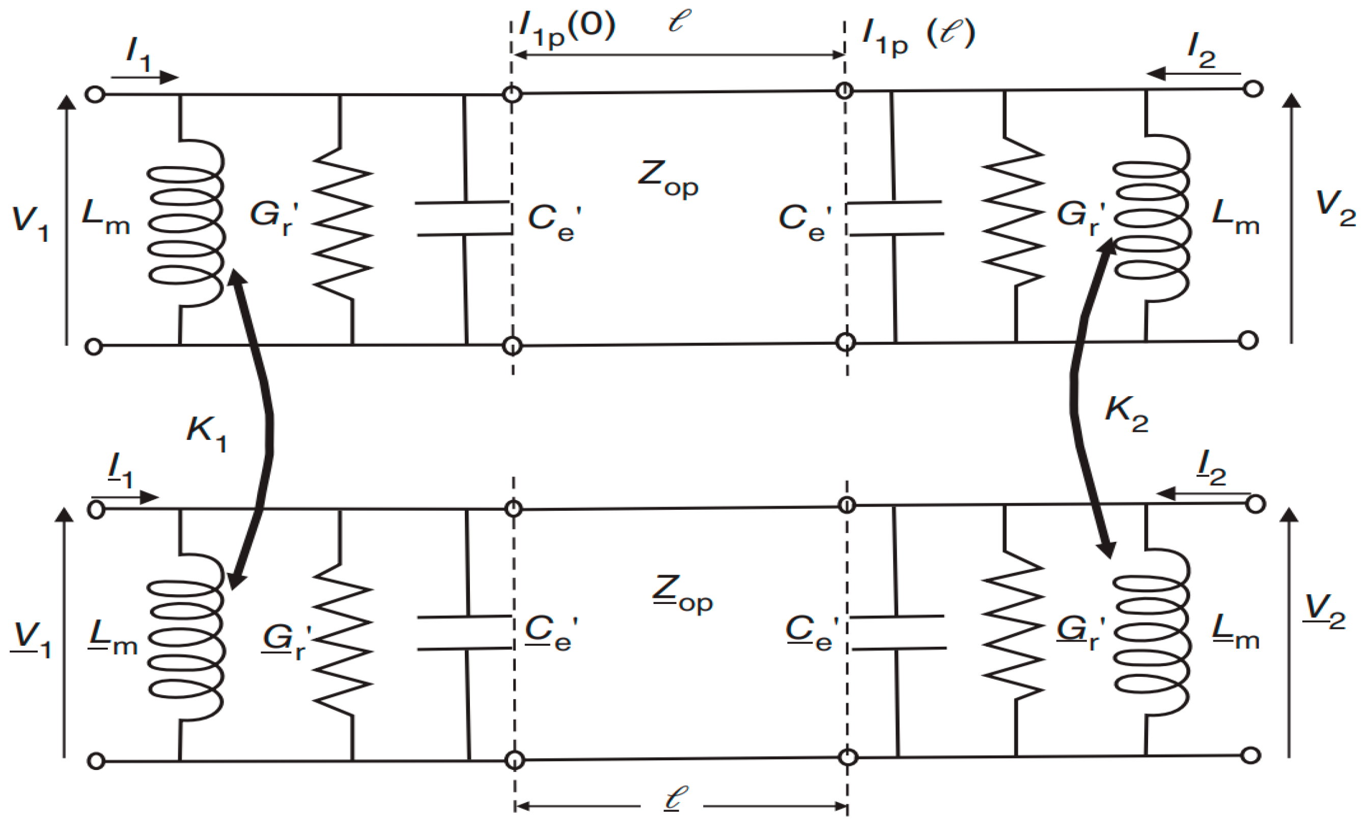
Based on the transmission line model depicted in
Figure 1 [
9], a single upper circuit, an equivalent circuit for a single rectangular patch antenna, is created, but it does not include the transformer inductors
.
Many studies have been published in the literature with the goal of reducing coupling and minimizing the correlation between transmitting and receiving antennas [
10,
11,
12]. Several attempts have been made to deal with surface wave suppression in order to reduce coupling and minimize correlation between transmitting and receiving antennas. Using the “Defect Ground Structure” between the two antennas [
13,
14] is one of the attempts. These structures necessitate calibrating the filter by slot width, and additionally, the chip resistors are loaded, which poses a problem at the millimeter-band level due to the small spacing between the antennas, thereby making it difficult to achieve the desired filter and increasing the risk of using the antennas’ ground plane, which causes noise or a change in radiation or frequency. Another type of attempt described in previous work [
7,
9] is to reduce coupling due to spatial electromagnetic fields by using meta-surface structures and to use the placement of a metamaterial absorber at the intermediate distance between two antennas. Other methods include parasitic elements [
15,
16], decoupling networks [
17,
18,
19], and metamaterial current reversal [
20] with the objective of introducing a second coupling path to cancel out the first. In [
14], an antenna interference cancellation chip is used to achieve the same goal (AICC). Alternative method for reducing surface waves is to use structures with an electromagnetic band gap [
21,
22], but these structures usually necessitate a large separation between antennas. Moreover, the research is not satisfied only with what is physical or mathematical, but also with optimal solutions with or without constraints, such as the use of genetic algorithms [
23] in the family of evolutionary algorithms.
Metamaterials, for instance, are engineered materials with unique properties that can enhance the performance of MIMO antennas by reducing mutual coupling among the MIMO elements. The orthogonal placement of MIMO elements is another technique that can improve isolation by placing antenna elements in a way that reduces the coupling between them. Parasitic elements placed between the inter space among MIMO elements can also reduce mutual coupling by changing the antenna’s radiation pattern.
We would like to present and conclude research that searches for the least expensive and most effective methods, as well as the methods that can be achieved, as there are methods that are difficult to achieve or costly in terms of material. In recent years, artificial magnetic conductor is appeared, which shows its effectiveness in several bands’ frequencies [
23]. It is also worth mentioning that AMCs are used in metamaterial antennas as a reflector to redirect the electromagnetic fields and enhance the directivity of the antennas. An AMC serves as a surface that reflects the electromagnetic waves in a specific direction, thereby improving the radiation pattern and gain of antennas [
24]. An AMC can be designed to reflect the electromagnetic fields of one antenna away from the other antennas, thus reducing mutual coupling and improving the performance of each antenna. Moreover, SIW antennas are integrated on a dielectric substrate using the substrate-integrated waveguide technology, which makes them smaller, more efficient, and easier to manufacture compared to traditional antennas [
25].
In this work, we study a very important band of frequency, which is 28 GHz, in terms of designing a new antenna array with important performances, as well as studying the coupling between two arrays by using an AMC. This research summarizes a group of parametric studies in order to reach an effective and practical result by using available and easy-to-achieve techniques. We propose the patch rectangles that are placed in a way that enables us to reduce mutual coupling, as well as using slot surface techniques in order to change the responses of patch matrices.
The antenna array suggested above can be used in radar systems that operate at 28 GHz, such as automotive radar systems and weather radar systems. The narrow bandwidth and mutual coupling reduction features can improve the accuracy and resolution of radar systems. With two separate antennas (reduced mutual coupling), it can be used as a transmitter and a receiver (monostatic antenna), with a frequency that is recommended. We took as an example the European Air Navigation Safety Organization EUROCONTROL, as part of its Airport Air Traffic Flow and Capacity Management (ATFCM) improvement project, which has published specifications for the implementation of the essential requirements of the A-SMGCS system that manifests the requirement for a non-cooperative sensor in the surveillance part in the Ka-band (Version 1.0—1 March 2018).
Simulation is an essential tool for the design and optimization of millimeter-wave antenna systems. In this study, we compared two popular simulation programs, ADS and CST, to evaluate the effectiveness of the proposed solution in reducing the mutual coupling between two antennas. We found that both software programs are capable of providing accurate and reliable results, but with slightly different simulation approaches.
3. Antenna Array Design
The first step to make a microstrip patch antenna array is to define the essential parameters, which is the desired frequency, the substrate used, as well as the method of feeding. In this work, we used Rogers RT 5880, which is known for its effectiveness in the millimetric range, with a thickness equal to 0.254 mm and a relative dielectric permittivity of 2.2, without forgetting that copper has been used as a conductor to design the antennas as well as feeder lines. In order to calculate the dimensions of the antenna, the mathematical equations and technical methods previously mentioned in the literature [
26] were used, according to the desired frequency of 28 GHz.
The antenna as a rectangular patch is assimilated to a cavity having two perfect electrical walls, and four perfect magnetic walls.
Figure 2 shows the basic geometry of a rectangular antenna with the dimensions (a,b) along the axes (o,
x,
y,
z).
In the literature [
27,
28] and depending on the mode of operation, we predicted the frequency of the operation of the antenna using the following equation:
In practice, the most used mode is (m, n, p) = (1, 0, 0) or (m, n, p) = (0, 1, 0). It should be noted that, in this work, the integer p, which is associated with the direction (), is always taken to be equal to 0 because, according to this dimension, the components of the electromagnetic field are constant inside the cavity.
As an illustration and for a dominant propagation mode TM010, the resonant frequency of the antenna is calculated from Equations (4) and (5) by replacing the values of m = 0 and n = 1 in Equation (3), without taking into account the effect of the edges.
Taking into account the modifications brought on by the effect of the edges, this frequency becomes
Hammerstad’s experimental formula provides this extension:
For effective radiation, the practical width according to the formula by Bahl and Bhartia for the patch is calculated as follows:
With a predefined substrate Rogers RT 5880, the use of (6) and (7), and a thickness equal to 0.254 mm, the antenna design at 28 GHz is shown in
Figure 3.
To match the line of characteristic impedance
to a load of impedance
, a quarter-wave line is inserted between the two. A schematic representation of the quarter-wave transformer matching technique is given in
Figure 4:
The impedance of the quarter-wave line is estimated as follows:
For the matching at the input, we chose the application of quarter-wave transformer matching, which gives us a good energy transfer to the antenna array.
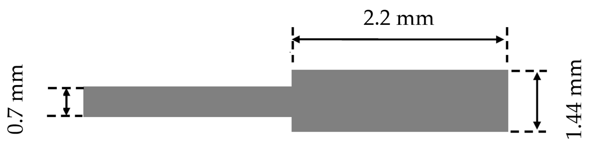
Figure 5 shows the transformer dimensions.
When the output impedances are chosen beforehand in the case of each antenna, the quarter-wave transformers are used to perform the impedance matching. The quarter-wave line can be placed at the input (
Figure 6).
We observe that
in parallel with
brings back
, and we use the relation of adaptation between two lines; the impedance of the quarter-wave sections is presented in
Figure 7 [
29]:
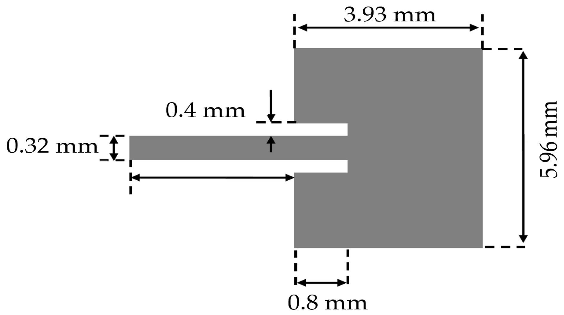
Figure 8 shows the proposed antenna array, which relies mainly on eight upper antennas and eight lower antennas that are separated at an estimated distance of 0.6
edge to edge (
= 6.34 mm), and the antennas are separated horizontally at an estimated distance of
which is from center to center
10 mm). The parametric study that was carried out to perform antenna dimension optimization by using the CST MW solver emerged of a rectangular microstrip antenna with the dimensions of w = 5.96 mm and L = 3.93, characterized by the line microstrip feeding method and power divider with an adapter at the input. The final optimized geometric parameters of the proposed microstrip antenna array are as follows:
= 0.7 mm,
= 0.2 mm,
= 0.58 mm,
= 0.8 mm,
= 1.44 mm,
= 4.6 mm,
= 2.3 mm,
= 2.3 mm,
= 19.86 mm,
= 17.66 mm,
= 13.6 mm, and
= 4 mm. The design of the antenna by the CST MW solver tool is shown in
Figure 9, where the final shape of the antenna appears from the front (a) and back (b) view, and
Figure 9c clearly shows the impedance matching at the desired frequency of 28 GHz, which is up to <−35 dB.
4. Mutual Coupling between Two Antenna Arrays (8 × 8) in the H-Plane Configuration
After we designed and simulated the unitary antenna array that matches the desired frequency listed in the previous part, a similar antenna array comprising 16 radiating elements was printed on the same substrate as the unitary array had been designed. However, the networking of the radiating elements causes electromagnetic interactions manifested by the modification of the distributions of the surface currents, which generate a modification of the electromagnetic behavior of the radiating elements and of the array.
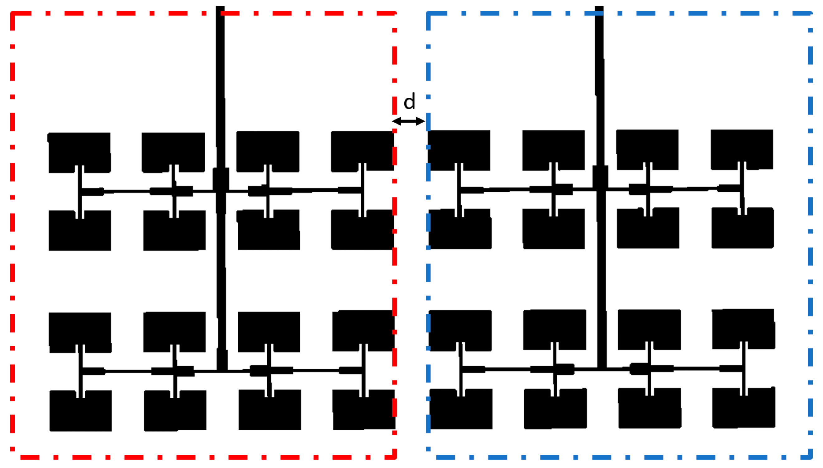
Figure 10 shows two antenna arrays designed on a single substrate and ground plane, where they are separated from each other by a distance “d”, which controls the interference between them, as it is important to separate them electromagnetically in order to guarantee the proper functioning of the antenna array, so that one antenna does not affect the other in the H-plane.
The mutual coupling between the two antenna arrays obviously depends on the distance between its elements. Indeed, the mutual coupling between these two antenna arrays printed on the same ground plane (
Figure 10) for different separations is illustrated in
Figure 11. Initially, distances equal to 𝑑 = 10.7 mm (1.0
) and 𝑑 = 8.56 mm (0.8
) between the two antenna arrays were chosen, but it could be seen that the mutual coupling between the array elements is always small. Then, with a distance equal to 𝑑 = 5.35 mm (0.539
) or 𝑑 = 3.5 mm (0.3
), the array elements become close to each other, which negatively affects the mutual coupling so that it becomes more important.
As we can see in
Figure 11, the coupling coefficient decreases linearly as the distance between the arrays increases. In essence, the strength of the electromagnetic coupling between the elements is inversely proportional to the distance between them. In order to improve decoupling in this array configuration, the simplest solution is to widen the distance between the array elements. However, this is not always the solution because when they share the same ground plane and the same substrate, there is always interference between them, and the challenge is to reduce the space as little as possible.
In this work, we studied the lowest possible distance (0.3
) due to the small size of the distances dealt with in the millimeter range. The results are shown in
Figure 12 where the (S
21) value is equal to −30 dB at 28 GHz. We can also observe that the reflection coefficient (S
11) at the center frequency (28 GHz) has become −34 dB. This coupling between the two antennas can be justified due to the surface waves between the two antennas in terms of the correlation between them.
S11 and S21 are the scattering parameters of a two-port network. In the case of two microstrip antennas, S11 represents the reflection coefficient of the first antenna due to its own impedance, while S21 represents the amount of signal coupled from the first antenna to the second antenna. If there is a significant overlap between S11 and S21, it indicates that the second antenna is receiving a significant amount of the signal radiated by the first antenna due to the strong coupling between them [
30,
31]. This can result in poor isolation between the two antennas and may lead to performance degradation of the overall system.
5. Design and Analysis of New Periodic Artificial Magnetic Conductor (AMC) Unit Cell
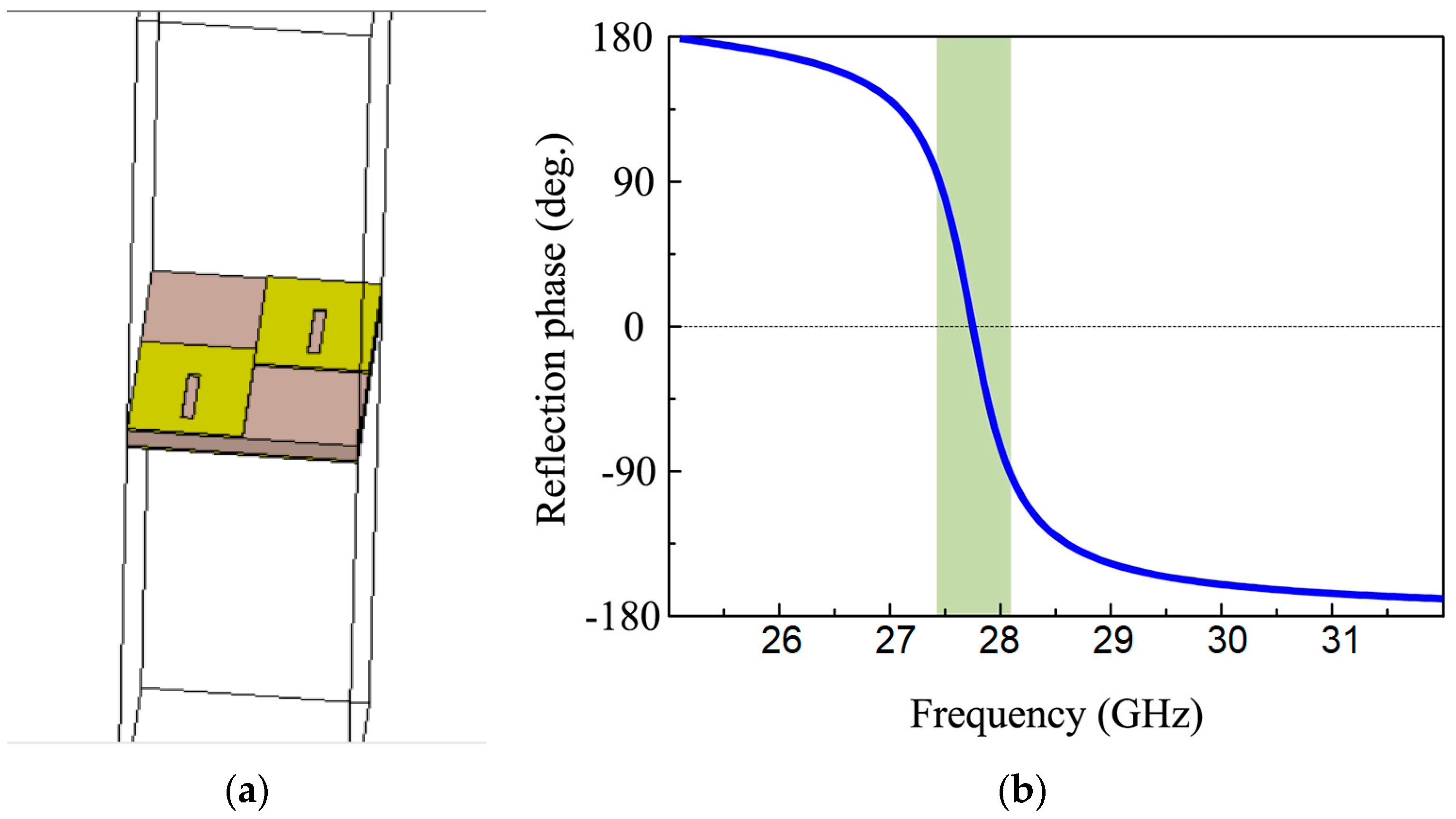
By designing transparent and electrically small unit cells and merging them in a defined spatial arrangement, a position-dependent phase distribution can be achieved with an AMC. The AMC can be exploited as a phase compensation surface to obtain an in-phase profile for directional emission. A high-impedance single-layer planar surface can have the property of an artificial magnetic conductor (AMC) with an electromagnetic bandgap where constructive signal interference occurs between the incident and reflected waves. In this paper, the rectangular-shaped unit cell is made on a Rogers RT5880 substrate having a dielectric constant of 2.2. It consists of two units connected to each other in a zigzag to exploit the minimal area in the millimeter band and achieve greater efficiency, as shown in
Figure 13.
According to
Figure 14, the AMC acts as a perfect magnetic conductor and offers a zero-reflection phase presented by the green bar in the figure. The design parameters of the unit cells are optimized to obtain a zero-reflection phase near 28 GHz, and the material properties are modified with the help of the tool CST Microwave.
The resonant frequency (
) and grid inductance (
) of the AMC, as shown in
Figure 15, can be expressed as follows:
As we can see that and are the dielectric slab inductance values; W is the width of the AMC; g is the gap between two neighboring cells; and a = 2 + g, where is the adjoining region between two plates.
The structure can be miniaturized by enhancing one of the following parameters: , , or . Increasing guides to a greater profile according to Equation (10). can be increased via enhancing either to (a/g) ratio or dielectric loading. In this design, increasing causes (a/g) ratio to increase, which, in turn, enhances as in (4).
The solution basically depends on using this structure of an artificial magnetic conductor (AMC) between two antennas to reduce the coupling between them by suppressing the magnetic field components, improving the isolation, reducing interference, and increasing the overall performance of the antenna system.
6. Two Printed Antenna Arrays in the H-Plane Configuration with Columns of New CMA Patterns
Figure 16 shows the overall design of the antenna proposed which contains two arrays of antennas made above the same substrate and the same ground plane, where they are separated by a distance of d estimated at 0.3
edge to edge, with the presence of columns of new CMA patterns in the middle.
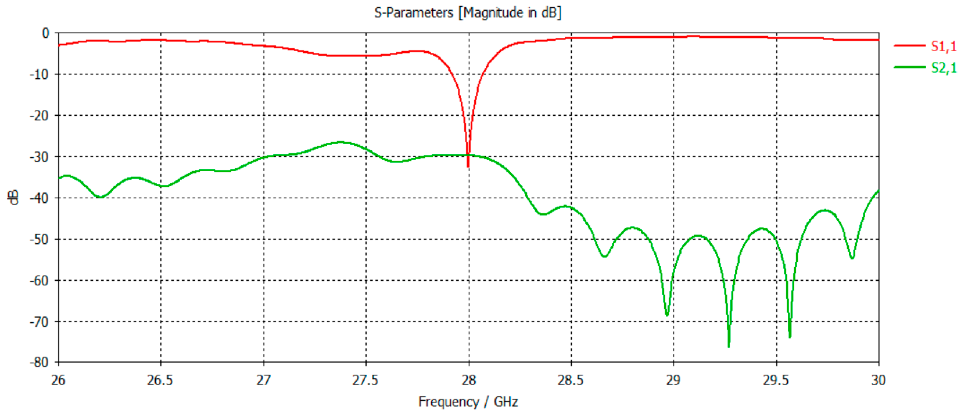
Figure 17 shows the great role played by the AMC as a solution to reduce interference between the two antennas, thanks to a reduction in the transmission coefficient (S21), which reaches −40 dB. We also notice a slight decrease in the reflection coefficient (S11), which has become −23 dB. It should be mentioned that the antenna response is still good at the frequency of 28 GHz that we want, and it also has conserved bandwidth.
The effect of the CMA structure in reducing the coupling between the two antennas at 28 GHz, where maximum coupling has occurred, takes place with a 10 dB reduction from −30 dB to −40 dB. Besides, the difference between the coefficients (reflection and transmission) equals 17 dB. The radiation pattern is one of the important points for any antenna.
Figure 18 shows the comparison of the radiation pattern in the E-plane and the H-plane, with the presence of the suggested solution compared to its absence. It should be noted that the AMC does neither affect the radiation pattern nor change its shape.
The surface current within the substrate for both antennas in
Figure 19 shows that the coupled surface waves have been reduced into the second antenna array. Thus, good isolation has been achieved after applying the AMC structure filter in between the compact antenna arrays. It is important to note that the AMC structure filter has succeeded in reducing the induced surface waves in the second antenna array, compared to the case of non-isolated antennas. This means that the compact antennas perform efficiently with good isolation at the operating frequency of 28 GHz.
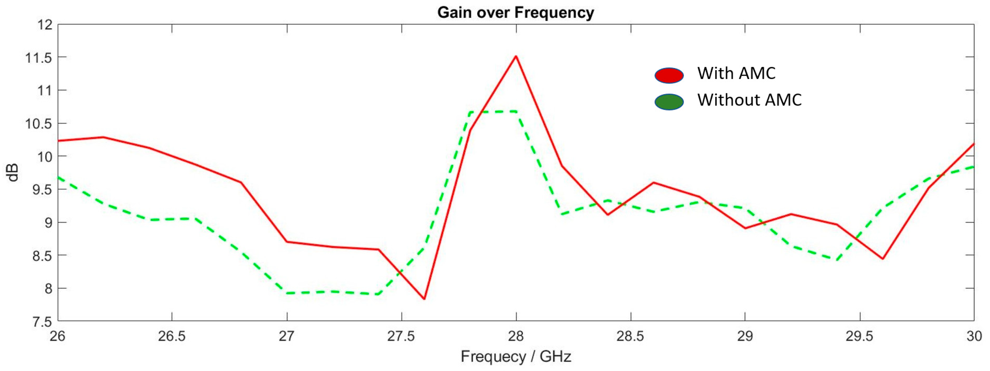
Among the most important points in the performance of antennas that needs be checked is the antenna gain, which is considered one of the most important factors of antennas in many applications.
Figure 20 below shows a comparison between the gain before and after the addition of the AMC structure, and it can be concluded that the gain is maintained with a clear increase in its value (11.5 dB); thus, the AMC structure provides an efficient solution without affecting our antenna values at different parameters.
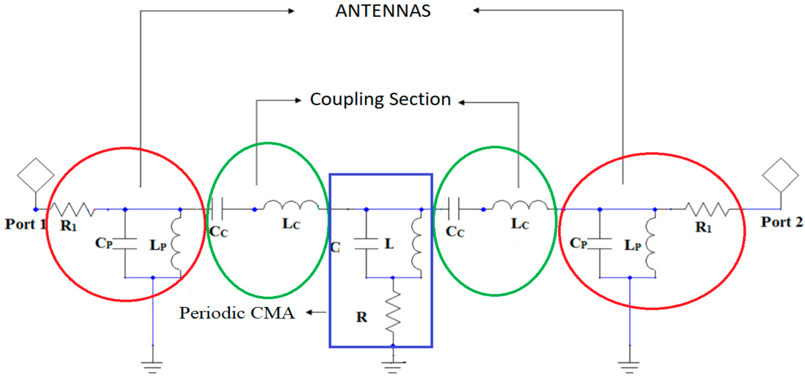
It could be remarked that the coupling between the patches is a combination of inductive (Lc) and capacitive (Cc) coupling, as seen in the coupling section in
Figure 21. The new periodic AMC cells, which are put with a zigzag structured task, reduce this coupling because they are created by a structure that bans the resonant frequency of 28 GHz of the antenna. The circuit parameters of the equivalent circuit model were extracted with the help of the optimizing and tuning features of Ansoft designer [
32,
33].
After performing the simulation with CST and obtaining satisfactory results, we wanted to confirm these results by using ADS, another simulation software with a slightly different simulation approach. ADS is a simulation software that allows the modeling of circuits in the time and frequency domains. In the time domain, the voltage and current vary in time at each point of a circuit. The layout of the general structure using ADS is shown in
Figure 22. The design parameters are the same, with two power gates that characterize the reflection and transmission coefficients.
The reflection coefficient as a function of frequency is presented in
Figure 23, which compares the results obtained using ADS and CST. Through this comparison, we can see that the obtained results match, which confirms the results of the reflection coefficient obtained in the previous simulation and provides us with a match in the desired frequency, which is 28 GHz.
Note that the simulation of the antenna by the ADS program shows us a larger estimated bandwidth between 27.6 GHz and 28.4 GHz. Regarding the transmission coefficient S21, it can be concluded from
Figure 24 that the results obtained are very good and show the estimated value of −40 dB. This is consistent with the results obtained previously, which confirms the effectiveness of the proposed solution aiming at minimizing the interference between the two antennas and obtaining good antenna performance.
We found that the results of CST are in agreement with those of ADS, confirming the effectiveness of the mutual coupling reduction method used in our study. This simulation comparison using two different software packages allowed us to evaluate the robustness and reliability of our simulation approach, as well as to strengthen the validity of our results.
Table 1 shows the performance of the various designs used to reduce mutual coupling and miniaturize devices. It can be said that each design has unique characteristics. Because of this, the proposed AMC structure shows better performance than those described in [
34,
35,
36,
37,
38,
39] in terms of mutual coupling reduction. Antenna arrays with the suggested decoupling structure were created, optimized for minimum spacing, and found to be appropriate for a variety of applications. The novel AMC structure with a zigzag position in between the antenna arrays has little influence on the radiation characteristics in terms of gain. The latter factor increases its values by about 0.40 dB when compared to the antenna structures without the AMC.
To determine how much the communication channels of the proposed antenna are isolated from one another, the value of the envelope correlation coefficient (ECC) is calculated. The value of ECC should be <0.5 for an antenna pair to perform diversity reasonably well.
In this section, the envelope correlation coefficient (ECC) using the MW CST formulation was studied for various applications with two-port antennas.
Figure 25 shows the simulated ECC before and after the installation of the EBG structure. The simulation results show excellent ECC after the installation of the AMC structure between the antenna elements. The AMC structure results in a reduced ECC of less than
.
Table 2 shows the comparison between previous papers and the proposed work. The ECC performance of the proposed antenna is compared with some other recently reported mmWave antennas [
38,
39,
40,
41]. The first thing to notice is that the antennas of the proposed structure are the closest, with a value of 0.3
. When compared to all other works, we can conclude that the proposed antenna results in a very good ECC, with a value of 0.00005.
7. Conclusions
In this work, we have validated a new AMC structure that reduces the mutual coupling between two antenna arrays which work at millimeter wave applications. The proposed AMC structure was validated firstly at 28 GHz, and we defined the electrical model to adjust this structure to other resonant frequency band. At the end, we associated this AMC with an antenna array, which permits a reduction in the coupling and dimensions of the whole antenna structure. The distance between the antenna arrays is reduced by a means of 0.3 for the edge-to-edge distance. The obtained results in comparison with the literature present a good isolation of −40 dB with a gain of 11.3 dB. The proposed antenna structure gives good advantages for its use in 5G application, as well as for Radars systems that can use it as a transmitting antenna and a receiving antenna without any effect on each other.


 ,
, 


