1. Introduction
The LoRa has gained much attention recently, from both academic and industrial fields, due to its capability to facilitate efficient Device-to-Device (D2D) communications and provide applications for different areas, including smart cities, health care, smart agriculture, smart metering, and so forth [
1,
2]. LoRa operates using the unlicensed ISM sub-GHz band and uses Chirp Spread Spectrum and Frequency Shift Keying modulation that makes it more robust to interference while transmitting to longer distances. It supports low power consumption and long-range transmission reaching up to several kilometers range. However, the long coverage, along with minimum transmission power, comes at the cost of a low data rate [
3].
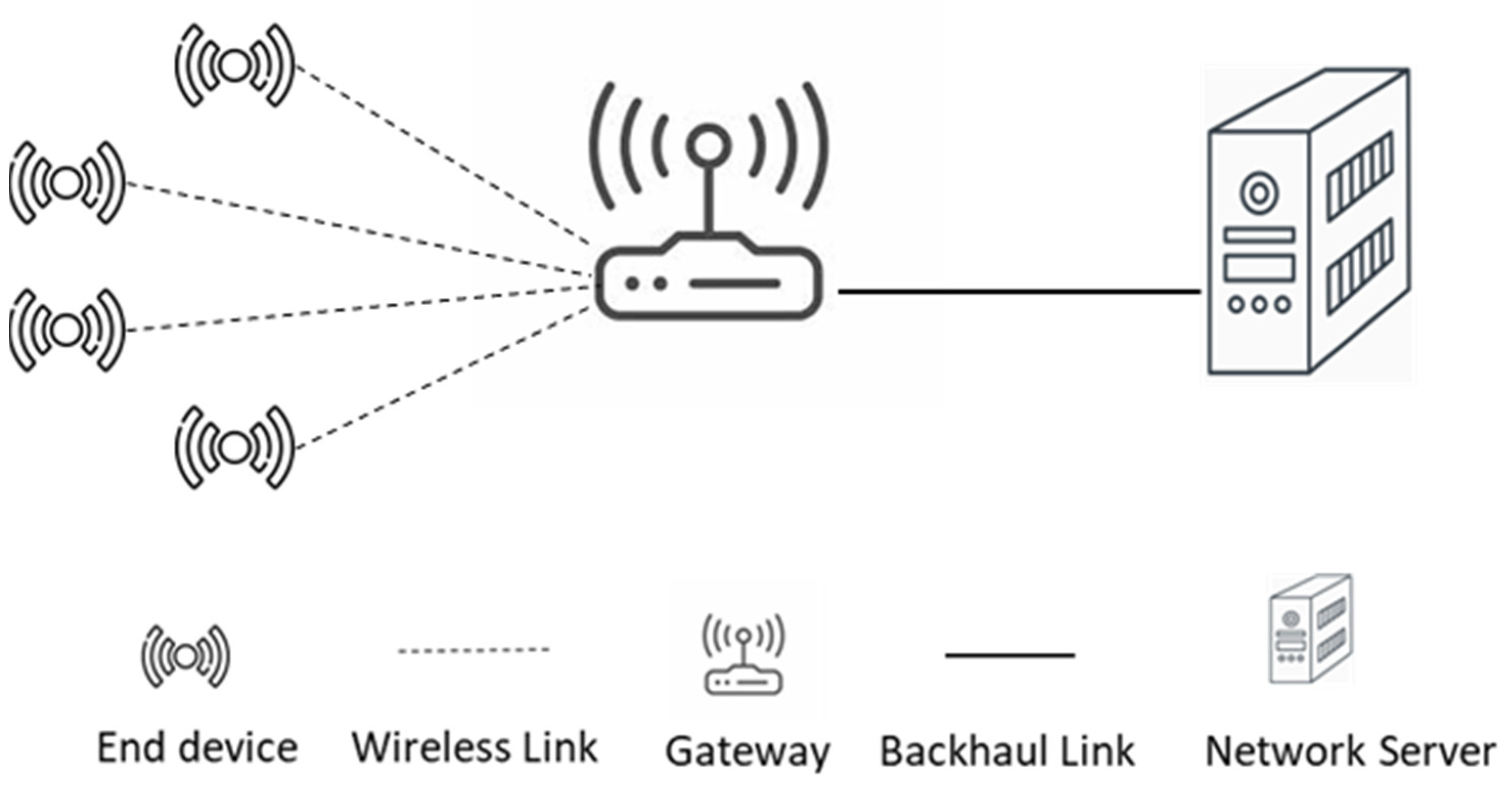
Long Range Wide Area Network (LoRaWAN) forms a star-of-star topology that contains end devices transmitting traffic to a gateway in a single-hop communication approach. Its basic design consists of end devices, gateways, and network servers, as shown in
Figure 1. End devices are in charge of collecting data by interacting with the surrounding environments based on the purpose of the deployed application. The collected data are transmitted by end devices to one or more gateways using Spreading Factors ranging from 7–12. Gateways take the responsibility of forwarding the received traffic to the network server. Gateways are connected to the network server via an IP network. The network architecture implies that an end device must be in the radio range of the gateway to transmit its traffic successfully. However, the radio range can be reduced due to different possible obstacles in the deployed environment, such as buildings, Trees, and mountains, hence affecting the overall efficiency of the network. In addition to that, some deployment scenarios require much longer coverage based on the purpose of the employed applications. Being out of the gateway range can also be a result of mobility if the end devices are mobile [
4]. Therefore, multi-hop LoRaWAN can fill in this gap, allowing out-of-the-range devices to transmit their traffic to the gateway utilizing other end devices that are in the range of the gateway without installing additional gateway devices. The use of additional gateways is considered impractical sometimes since a gateway requires main power that would be difficult to supply in some remote locations. Moreover, employing multi-hop LoRaWAN would be justified for avoiding collisions since faraway devices can use a smaller Spreading Factor (SF). The use of lower SF reduces the Time-on-Air (TOA) a packet requires to travel to its destination. Thus decreasing the chance of collisions.
LoRaWAN provides support for three different Medium Access Control (MAC) modes to satisfy different application requirements. An end device should operate according to one of the three classes: class A, class B, or class C [
5]. Class A functions based on the application need. It offers bidirectional communication between the device and the gateway based on the ALOHA protocol. The communication starts with an uplink transmission, which is followed by two receive windows that can be used for downlink communication. It is considered the lowest power device mode. Class B, on the other hand, adopts synchronization of end devices with the network server to enable more receive windows in addition to the two receive windows of class A. A time synchronization beacon is sent periodically by a gateway to allow end devices to synchronize their clocks and, hence, entitle the network server to know the moment that an end device is awake. It targets reducing the delay for the network server to transmit downlink data to an end device. Class C, finally, provides the least latency for downlink traffic since it opens an almost continuous receive window. The receive window is closed only when the device is transmitting. However, class C-enabled devices consume more power compared to classes A and B.
LoRaWAN employs an Adaptive Data Rate (ADR) mechanism as a method to adjust and control some of the network configuration parameters to reach an optimal operation [
6]. ADR’s main motivation is to efficiently set the data rate, which consequently affects network capacity and power consumption [
7]. It operates on two sides: the network server and the end devices. The one at the end device side is designed to entitle an end device to increase its transmission range via increasing transmission power and spreading factor. The end device maintains a counter to figure out whether it has received any ADR command or downlink messages from the server. If the counter reaches a threshold, the transmission power and spreading factor are accordingly increased. On the other hand, the network server ADR works on demand as requested by an end device. The network server measures the link budget between itself and an end device based on the last 20 packets exchanged. The collected information is used by the network server to first decrease the spreading factor and then adjust the transmission power. The recommendation is finally sent to the end device.
Several works have been proposed in the literature to handle the deployment of multi-hop LoRaWAN. Most of the proposed works are dependent on some assumptions which make their solutions appropriate for special cases. An example of that is the assumption of the use of synchronization where end devices and gateway are synchronized. Such synchronization would enable communicating devices to control activity time. This, however, contradicts the typical MAC approach used by LoRaWAN, ALOHA protocol. Other solutions assume the prior knowledge of the network topology to allow the use of some specific network construction technique, such as building a tree topology.
This paper proposes Listen-To-Talk-based Multi-hop LoRaWAN (LTM-LoRaWAN) to support multi-hop communication in LoRaWAN. The proposed system first entitles an end device to determine whether or not the device is in the range of a gateway by optimizing the existing ADR mechanism. The proposed system then provides a lightweight procedure for transmitting and forwarding out-of-range device traffic to a gateway. This requires the proposed system to employ a different mechanism for medium access similar to Listen-before-Talk. The contribution of this paper is the detailed design of LTM-LoRaWAN and a comprehensive simulative evaluation of the proposed system. Moreover, the paper provides a comparative assessment of the proposed multi-hop system compared to one-hop LoRaWAN using several performance metrics.
The remainder of this paper has been organized as follows.
Section 2 introduces the existing related work in the literature. The proposed system is then presented in
Section 3. The evaluation of the proposed system is addressed in
Section 4. The section begins by introducing the network model and the configuration parameters. It then defines the evaluation metric and introduces and discusses the result of the evaluation. The conclusion is finally drawn in
Section 5.
2. Related Works
LoRaWAN multi-hop communication approach has been investigated by several publications in the literature to find out its feasibility in increasing network coverage. It has been used in several LoRaWAN IoT applications, such as environmental monitoring [
8], underground monitoring [
9], oil pipeline detection [
10], and smart cities [
11]. This part of the paper covers current research related more to the relaying approaches rather than the routing. A comprehensive survey for multi-hop communication in the LoRaWAN field can be found in [
3,
12,
13].
The work in [
14] used a special node (Enhanced Node) to extend the range of the transmitted traffic. The Enhanced node requires a continuous power supply to stay ready for any incoming traffic. It operates at the link layer level. The Enhanced node duty is to replicate any received messages without enforcing any limitation if the incoming traffic does not require confirmation. However, the subsequent receive windows are used for confirmed traffic along with synchronizing the incoming and sending paths. In the case of downlink traffic, a gateway is required to transmit the downlink traffic after the first receive window of the e-node, whereas the e-node is required to send the downlink after the end of the second receive window of the initial uplink message. The feasibility of the e-node proposal was tested in 2800
industrial laboratory. The e-node was located about 100 m away from the gateway, and few nodes transmitting traffic were used.
The work in [
15] suggested the addition of a relay device after the deployment of the network. The relay devices are placed in locations to serve far away LoRaWAN end devices and work as intermediate entities, relaying the traffic toward the gateway. The proposed relay nodes are different from standard end devices, where their main task is to extend the coverage of the LoRaWAN network via receiving and forwarding operations. One of the proposal’s main considerations was to select the most appropriate location for the relay device. The relay devices can switch between active and sleep mode based on the analysis of the uplink traffic pattern. In addition, they are proposed as transparent where the end devices and the gateways are not aware of the existence of such relay devices. The proposed approach assumed two phases for a relay device operation. The first is when the relay device stays in active mode to discover end nodes within its vicinity and observe uplink traffic. Once a relay device finishes its observation phase, it moves to the second phase, the data forwarding stage. In this stage, the relay device is in sleep mode and wakes up periodically to receive and forward uplink traffic.
On-demand forwarding has been used in [
16], where relay nodes forward the received packet if and only if the network server does not receive it. This was achieved using an on-demand feedback mechanism by the server to inform the relay nodes of the status of a particular packet. The proposal made use of priority-based forwarding as well. The priority is organized based on the RSSI, which is distributed by the network server in advance of transmitting the feedback message. The relaying node with the highest priority can forward a packet immediately when it receives a feedback message from the server. Other relaying nodes should stay in active mode all the time, listening to the transmission from the relaying node with higher priority. Once the relay with higher priority is finished, the other can start forwarding their messages. The proposal was evaluated in simulation and achieved a similar delivery ratio with a smaller number of retransmissions.
The work in [
11] proposed two architectures to serve multiple hops in LoRaWAN. The first architecture assumes that an end device can operate as a relay node to forward faraway node traffic toward a gateway. However, the paper lacks a description of how the forwarding mechanism works. It claimed that the relay node operates a decode and forward mechanism. Moreover, the work evaluated the proposal using real experiments with a few devices that were placed only a few hundred meters from each other. The second architecture divides the network topology into several clusters. Each cluster has its gateway, which forwards the traffic towards a main gateway. The architecture was evaluated in a 290 m × 210 m topology covering two clusters.
An opportunistic protocol for LoRa, named LoRaOpp, was proposed in [
17]. It uses some opportunistic mechanisms, such as source routing and spray and focus, which have been studied to handle disruption and opportunistic networking in the literature. These mechanisms were used to limit the number of forwarded packets in the network. The proposal assumes three different LoRa devices: end node, peer node, and gateways. It assumed that LoRa devices are capable of storing data in case the next node in the path is not reachable until the following contact opportunity. LoRaOpp used broadcasting to allow gateways and end devices to announce their existence via broadcasting dedicated packets frequently. The protocol uses a collision detection mechanism and retransmission technique to avoid data loss. It was evaluated experimentally in an outdoor environment with seven end devices, including the gateway. An emulation was also used to evaluate the performance of the proposal in larger networks that contain up to 100 LoRa devices.
Based on the LoRa physical layer, the work in [
18] proposed a mesh LoRaWAN named LoRaMesh aiming to extend the coverage of LoRaWAN networks. To implement multi-hop functionality, the proposed system modified several components of LoRaWAN, including the implementation of the network server, reception windows, and packet headers to facilitate retransmission. Bacon flooding is initiated by Gateways and is used to keep time synchronization among devices. The synchronization bacon is then retransmitted by one hop device to other LoRaWAN devices. A rule-based mechanism is used to set a fixed transmission schedule for every single device at the beginning of the network, where each child device is assigned a slot time for transmission. The proposal assumes a routing procedure with a global knowledge of locations and path loss between devices and the gateway to calculate routing paths and build tree structure routing for the whole network. The network server determines parent devices as well as children’s devices. The proposal was implemented in NS-3, evaluated, and compared to single-hop LoRaWAN.
A genetic algorithm was used in [
19] to optimize the performance of the LoRaWAN network in terms of latency and coverage probability. The study investigated the performance of dual-hop LoRaWAN following the cooperative communication strategy where devices cooperate to carry out data transmission. The study then utilized a genetic algorithm to obtain the LoRa device’s optimal transmission configuration in terms of received power, where it is at its maximum value. The achieved values are then utilized to enhance the performance regarding coverage and latency. The proposal was simulated in MATLAB, and it is reported that it improved the coverage of the network by about 20%.
A two-hop real-time LoRa was proposed in [
20] and extended in [
21]. The proposed protocol contains two main phases: tree topology construction and slot scheduling. In the first phase, the protocol constructs a tree topology of the network based on the quality of the links between end devices and the gateway. The tree topology is then used by the network server to perform slot scheduling between one-hop and two-hop neighbors of the gateways. The one-hop end devices can transmit their uplink traffic directly, and the two-hop devices use one of the one-hop devices as a relaying node to transmit their traffic on the scheduled slots. The proposal optimizes broadcasting to build the tree topology where a gateway is required to broadcast a Tree Construction Request that will be received by all possible one-hop devices. The Tree Construction Request is then re-broadcast to other possible two-hop devices. Two-hop devices evaluate the received Tree Construction Requests to decide their parents. All end devices are required to transmit traffic periodically to maintain the topology. The proposal was evaluated in a testbed containing one gateway and ten nodes, which were located manually to have two-hop nodes in the topology.
The work in [
22,
23] proposed a multi-hop communication protocol based on a centralized MAC LoRaWAN instead of the MAC mechanisms used by standard LoRaWAN, such as Listen Before Talk and ALOHA. It uses Time Division Multiple Access (TDMA) as the medium access strategy to target real-time IoT applications. The main goal of the proposed system was to decrease the Time on Air (ToA) by utilizing a multi-hop technique to allow the LoRa device to use a smaller spreading factor. The proposed solution adopted a hierarchical topology approach. The end devices are organized in advance of the network operation; hence, the network topology is assumed to be priorly known. The whole topology is divided into several layers, where the first layer constitutes devices with one hop distance from the network gateway. Relaying of messages is restricted to devices that belong to adjacent layers. The system assumes the usage of devices that exclusively work as relay devices. It also uses frequent Bacon broadcasting to maintain node synchronization in the network. The proposed system was evaluated in a simulation environment using OMNeT++ with three layers of tree topology containing up to 54 nodes.
3. Proposed Protocol Design
This paper proposes a novel lightweight mechanism based on LoRaWAN to enable multi-hop communication named Listen-to-Talk-based Multi-hop LoRaWAN (LTM-LoRaWAN). The main goal is to allow out-of-range devices to deliver their traffic to the gateway while keeping the typical LoRaWAN functionalities as simple as possible. This is achieved by utilizing other in-range devices to forward the messages toward the gateway. The proposed system avoids any use of complex routing mechanisms or routing topology construction, nor does it use special entities or assign specific tasks to specific devices. This is to keep the functionality of the proposed one as similar as possible to standard LoRaWAN. The network model under investigation contains a network server, a gateway, and hundreds of LoRaWAN devices. No specific rules or functionalities are assigned to any device before the network deployment. All the end devices are standard devices. However, the proposed system entitles the devices to opt for forwarding their traffic based on their needs. Moreover, the proposed system introduces a lightweight mechanism within the end device’s functionalities to allow them to participate in traffic forwarding.
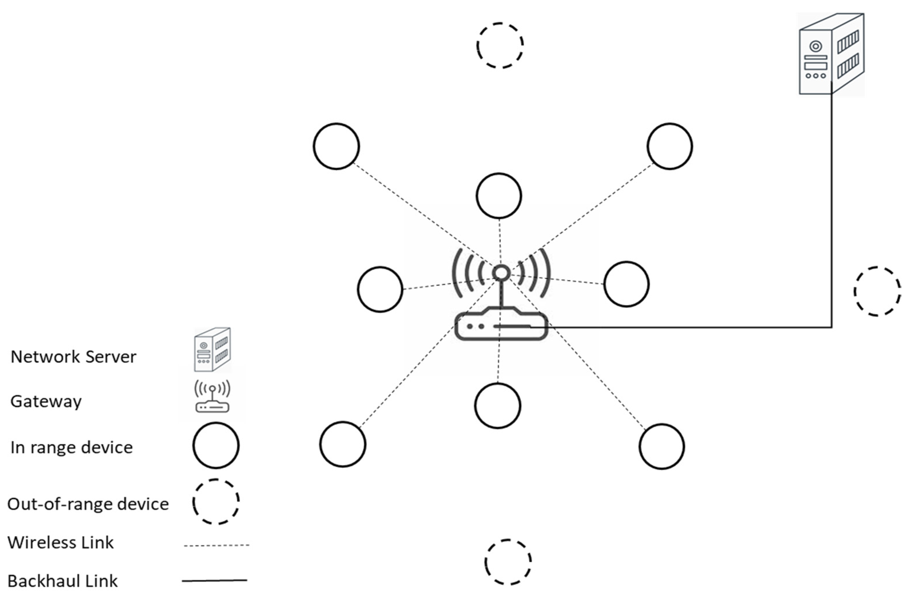
Figure 2 displays a simple representation of the considered LoRaWAN network containing out-of-range end devices in addition to standard LoRaWAN end devices.
The proposed protocol involves two main phases to carry out delivering faraway device traffic to the gateway. The first phase is related to out-of-range LoRaWAN devices. It covers the process according to which a device can identify itself as being out of the range of the gateway. The second phase is related to the process of transmitting and forwarding out-of-coverage devices’ traffic. The latter phase contains the proposed strategies that are embedded in the procedure of both out-of-range devices and other in-range devices.
3.1. Identification of Being out of a Gateway Coverage
The first phase in the proposed system is concerned with a device identifying itself as out of the gateway coverage. Therefore, delivering its messages requires collaboration from other LoRaWAN devices to pass on its messages to the gateway. The standard LoRaWAN offers an Adaptive Date Rate (ADR) to allow devices to control their data rate and, hence, increase the network efficiency. ADR operates on two different sides: the network server side and the end devices side. The ADR feature at the LoRaWAN device side is optimized and modified by the proposed system to serve for identifying out-of-range devices. ADR employs a counter to maintain connectivity with the gateway. The counter is increased for each transmission and reset to zero value if the device receives an ADR command or a downlink message. In the case that the counter reaches a predefined limit, the device must regain connectivity by increasing its transmission power and spreading factor, which allows longer radio coverage with a lower data rate. This feature has been modified and utilized by the proposed system to identify being out of the radio range of the gateway [
24].
When the spreading factor has been increased to its maximum value, 12, with no ADR command from the network server being received nor a downlink message for a predefined limit, it indicates that the end device is out of the gateway coverage even though it is using the maximum available SF and transmission power. The limit is defined by standard LoRaWAN as the sum of the number of acknowledgment limits and the number of acknowledgment delays. Once an end device reaches this point, it is regarded by the proposed system as an out-of-range end device, and its ADR mechanism is disabled. The proposed system then forces the current device to switch to the proposed mechanism LTM-LoRaWAN to be able to transmit its traffic despite being out of the coverage of the gateway. Algorithm 1 shows the pseudocode for identifying out-of-coverage LoRaWAN devices.
| Algorithm 1: Pseudocode for Identifying Out-of-Range Device |
| 1: | PKT: End device Packet for transmission |
| 2: | ADR_ACK_CNT: ADR Acknowledgement Counter |
| 3: | ADR_ACK_LMT: ADR Acknowledgement Limit |
| 4: | ADR_ACK_DLY: ADR Acknowledgement Delay |
| 5: | SF: Spreading Factor |
| 6: | For each PKT do |
| 7: | increase ADR_ACK_CNT |
| 8: | If ADR_ACK_CNT >=(ADR_ACK_LMT + ADR_ACK_DLY)
& SF = 12 & Transmission power is maximum |
| 9: | set forwarding field to 1 |
| 10: | set Time_To_Live to 1 |
| 11: | initialize ADR_ACK_CNT to zero |
| 12: |
End if |
| 13: |
End for |
3.2. Frame Structure
The uplink message format is re-engineered in the proposed system to contain the need for forwarding a message being transmitted by an end device. A MAC payload for a LoRaWAN frame consists of three parts: Frame Header (FHDR), Frame Port (FPORT), and Frame Payload (FRMPAYLOAD). The frame Header itself is divided into four sections with a size not exceeding 22 bytes, as shown in
Figure 3. The frame option (FOpts) part is up to 15 bytes field and is used for MAC commands. A portion of the FOpts is used in the proposed system to hold the status of a transmitted message regarding the need for forwarding by other end devices in the network.
Figure 3 shows the new format as well as the LoRaWAN frame header.
Moreover, an end device in the proposed system is required to attach a Time-To-Live (TTL) value to its messages. The TTL is positioned next to the Forwarding status field in the new structure of the frame header. The TTL is assigned 1 in messages generated by an out-of-range device and 0 in messages issued by end devices that reside within the coverage of the gateway. This is used to control the broadcasting of out-of-range devices’ traffic and provide loop avoidance. The TTL is decreased to 0 once the message is forwarded by one or more of the neighbors of the out-of-the-range device. Therefore, the message no longer gets forwarded in case it has been received by other end devices, hence decreasing the chance of storming the network with the introduced forwarding mechanism and providing loop avoidance.
3.3. MAC Mechanism to Facilitate Transmission and Forwarding
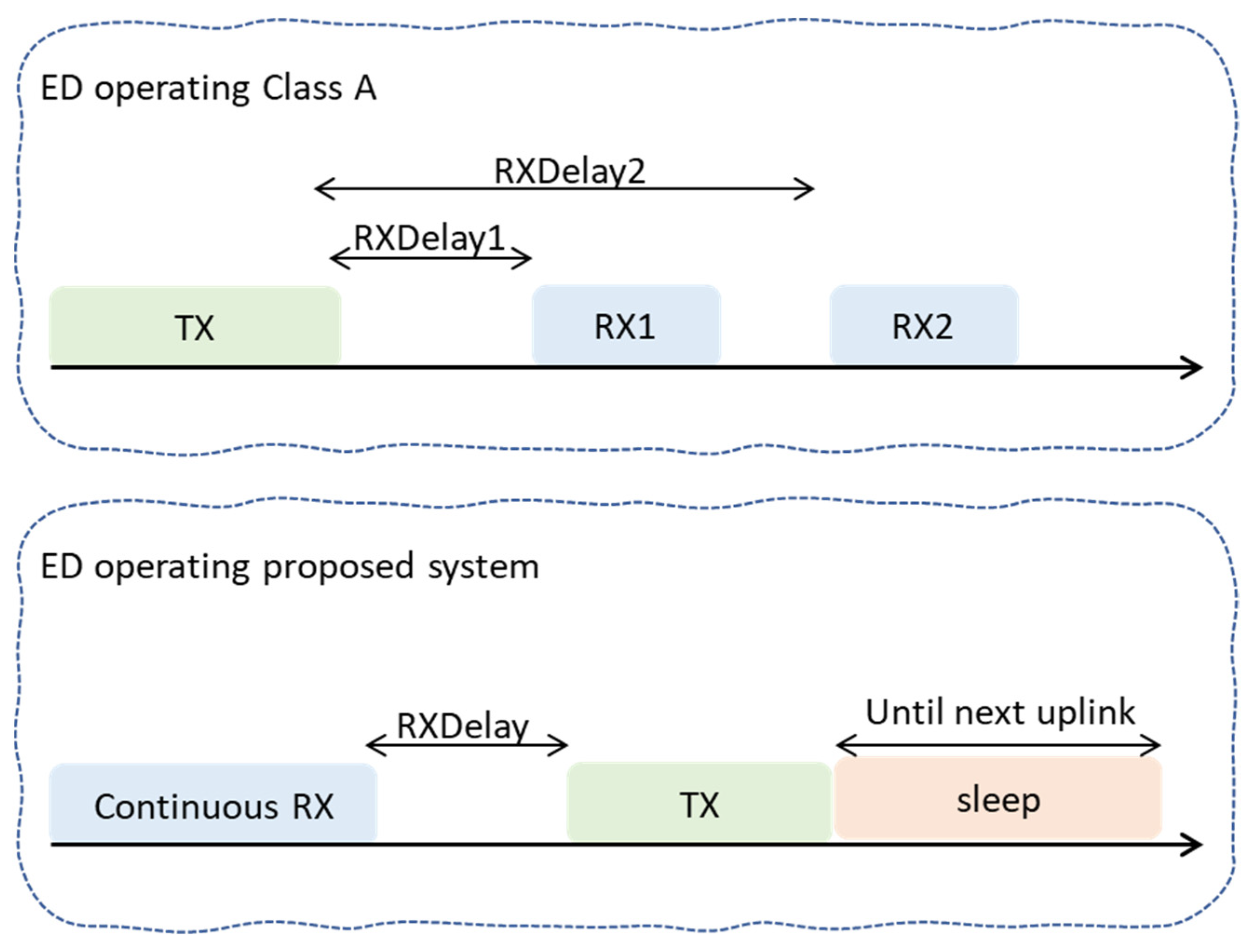
End devices in the proposed system implement the class A approach, which is the most implemented class, consumes the least amount of power compared to other classes, and provides the least functionalities of the LoRaWAN network. Similar to other classes, class A uses ALOHA as the medium access algorithm. An uplink transmission by an end device is followed by two short receive windows named RX1 and RX2. However, the proposed system opts for optimizing the ALOHA protocol by out-of-range devices to allow them to deliver their traffic to the main network server. Thus extending the coverage of the LoRaWAN network using a multi-hop strategy. Once an end device finds itself out of the range of the gateway based on phase one, it immediately employs a different scheme for medium access similar to Listen-Before-Talk (LBT) named Listen-To-Talk (LTT).
Differently from the traditional access scheme employed using the standard end device, the proposed medium access scheme forbids out-of-range devices to directly transmit their messages whenever they need to. Instead, the proposed system requires an out-of-range device to employ the Listen-To-Talk scheme. According to the utilized LTT, an out-of-range device starts the lifecycle of transmission by listening to other neighboring devices in advance of transmitting its traffic. Once the device senses an uplink transmission, the Listening phase of the LTT mechanism is finished. The listened uplink transmission indicates that there would be two receive windows following the transmission. This is possible since end devices use broadcasting when transmitting their messages toward LoRaWAN gateways, and hence, such transmission by closer-to-the-edge devices can be sensed by out-of-range devices. Thus, the proposed system utilizes these two windows to coincide out-of-range device transmission with one of the aforementioned two receive windows. In other words, the two receive windows of standard end devices are utilized by out-of-range devices to initiate their uplink communication. This constitutes the Talk phase of the employed LTT by the out-of-range device.
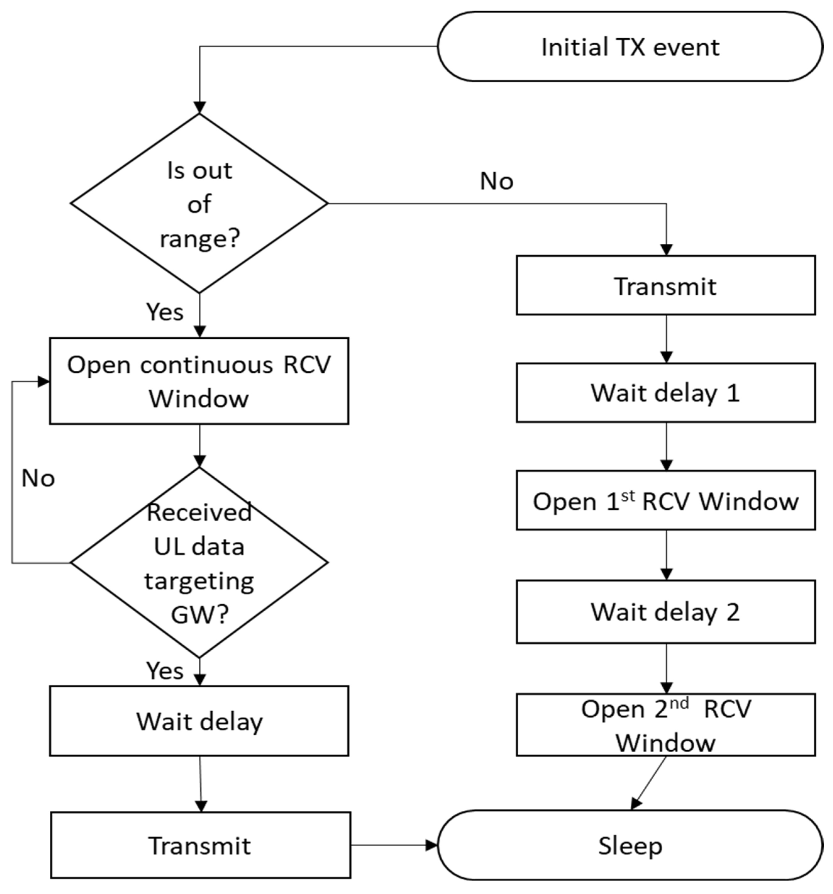
Figure 4 shows the standard MAC operations for in-range and the LTT operation for out-of-range devices. After sensing and receiving a transmission, an out-of-range device delays its transmission for a while, then starts the transmission, hoping that such uplink traffic would coincide with one of the two receive windows. Once the transmission finishes, the end device sleeps until the next transmission is needed. The process of transmitting an uplink message for an end device in the proposed system is illustrated in
Figure 5.
The second part of the second phase is the forwarding procedure that must be accomplished using other LoRaWAN end devices that have just received the message from an out-of-range device. The forwarding end device is expected to receive the message for forwarding during one of its two receive windows. Upon receiving and recognizing the message as a message for forwarding, the forwarding device cancels the other receiving window if it was in the first, sets its transmission parameters, such as SF and transmission power, to the received frame, and starts the transmission. It should be noted that the forwarding end device does not open any other receive windows and should go to sleep mode after the forwarding procedure. The pseudocode for the forwarding procedure is shown in Algorithm 2.
| Algorithm 2: Pseudocode for the Forwarding Procedure |
| 1: | PKT: End device Packet for transmission |
| 2: | SF: Spreading Factor |
| 3: | TP: Transmission Power |
| 4: | TTL: Time-To-Live |
| 5: | RCVW: Receive Window |
| 6: | For each received PKT do |
| 7: | If (PKT for forwarding & I can see the gateway) |
| 8: | decrease PKT’s TTL |
| 9: | set SF & TP |
| 10: | cancel other RCVW if any |
| 11: | insert PKT into Transmission Queue |
| 12: | schedule PKT for transmission |
| 13: |
End if |
| 14: |
End for |
5. Conclusions
In this paper, a multi-hop system for the LoRaWAN network, named Listen-To-Talk-based Multi-hop LoRaWAN (LTM-LoRaWAN), is proposed. It targets extending the coverage of the LoRaWAN network when increasing the number of gateways is infeasible due to gateway deployment constraints. The proposed system is dynamic and flexible enough to be adopted using different LoRaWAN applications that require an extended coverage capability while ensuring delivery reliability. The proposed system in this paper does not require any specific topology. It can be deployed using standard LoRaWAN end devices. The protocol ensures the ability of devices to discover themselves if they are out of the gateway coverage. This would be the trigger of the protocol operation. For out-of-coverage devices, the proposed system utilizes a procedure of transmission using a special type of medium access mechanism. The proposed system also entitles any standard end device that receives traffic from out-of-range devices to forward such traffic to a gateway while operating as a standard LoRaWAN device.
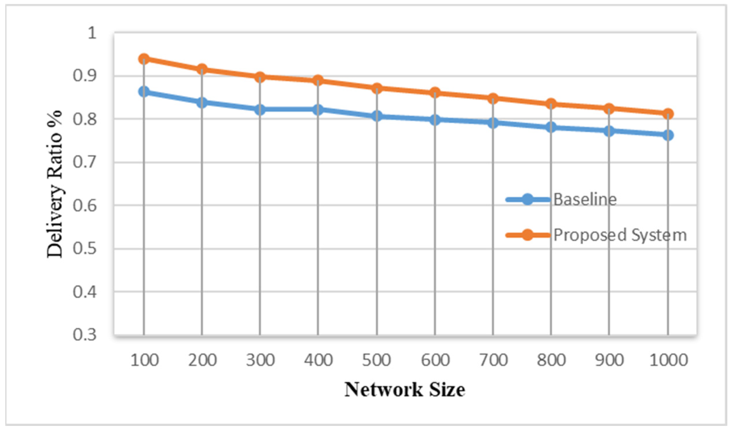
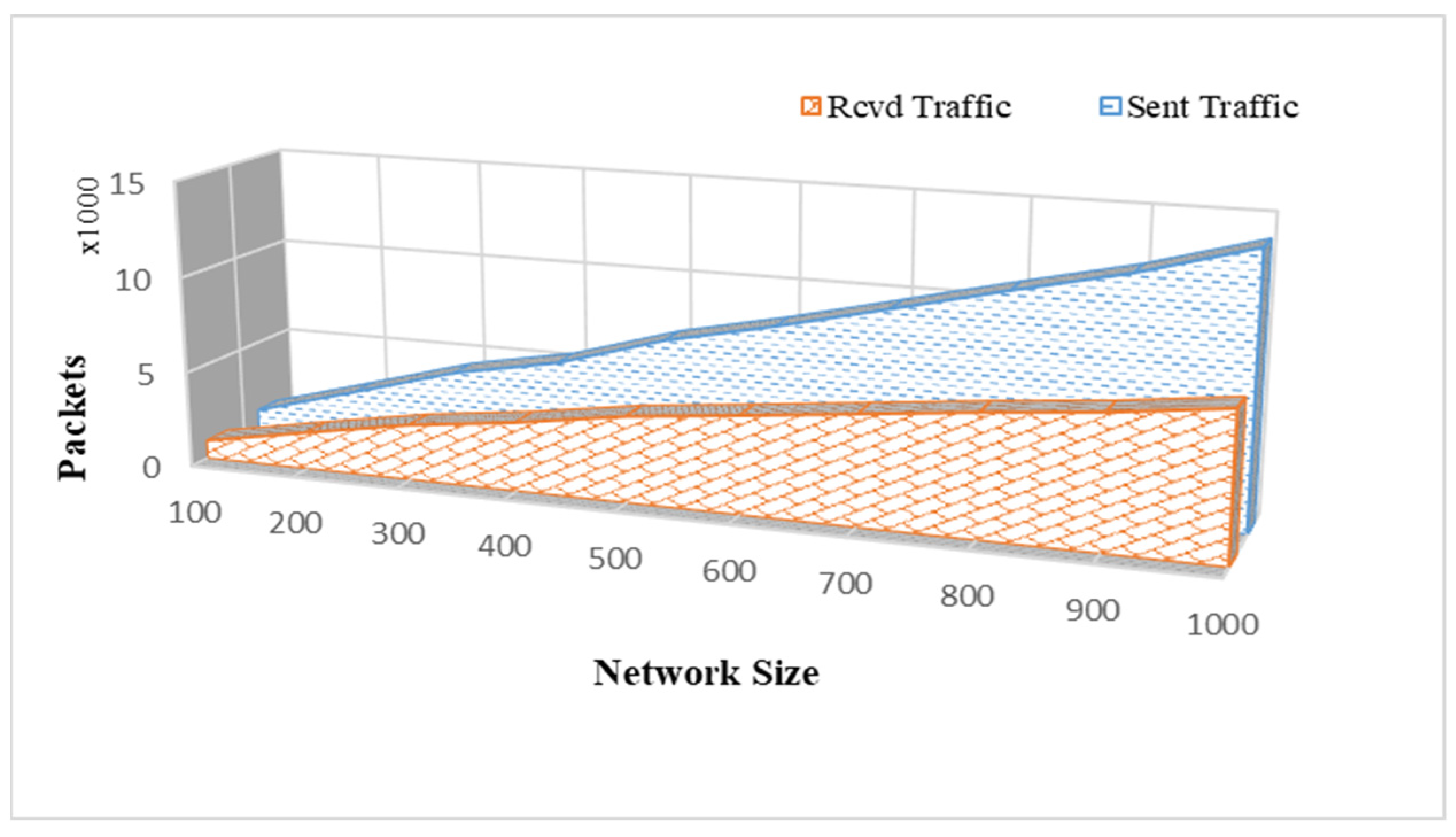
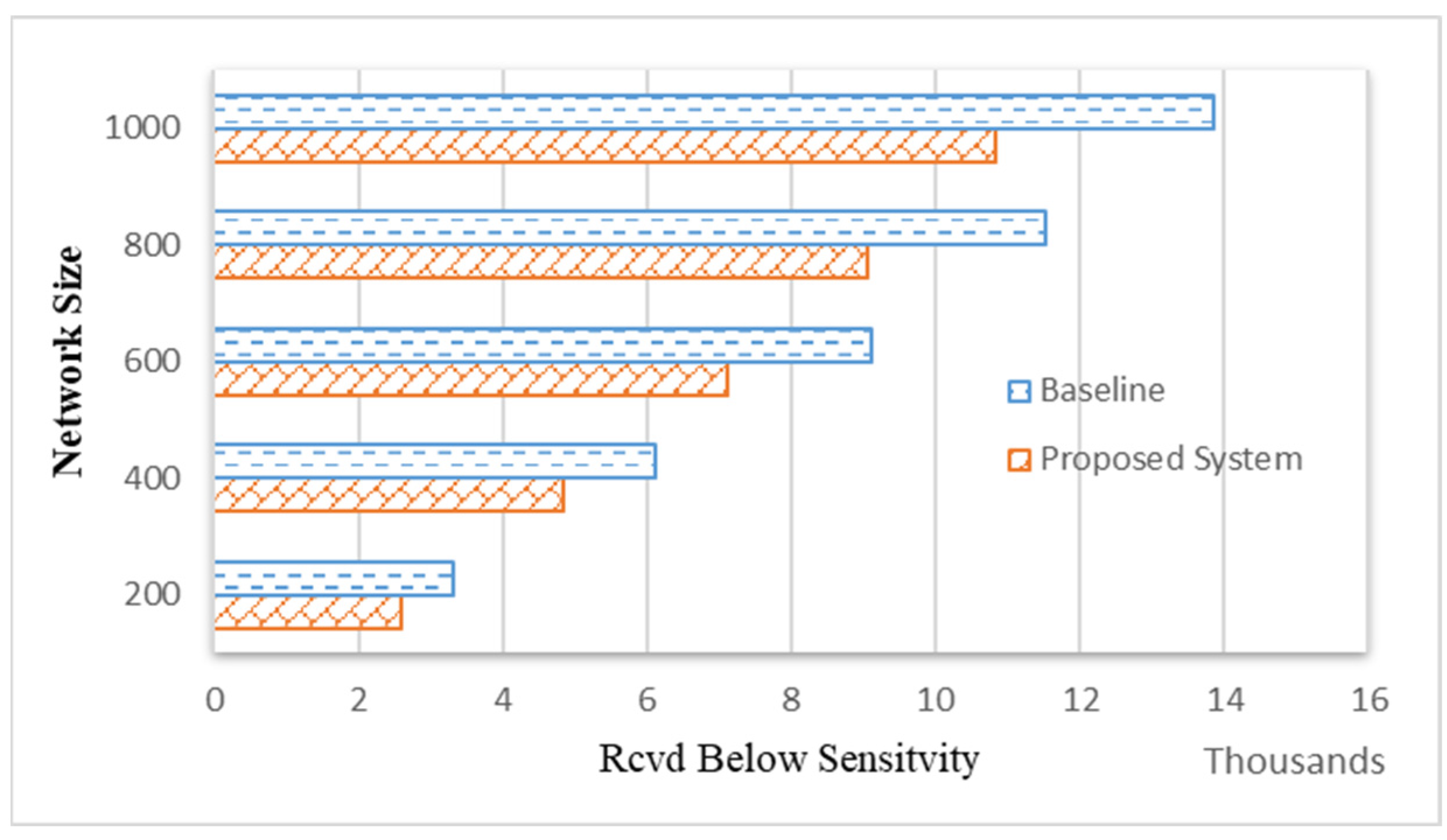
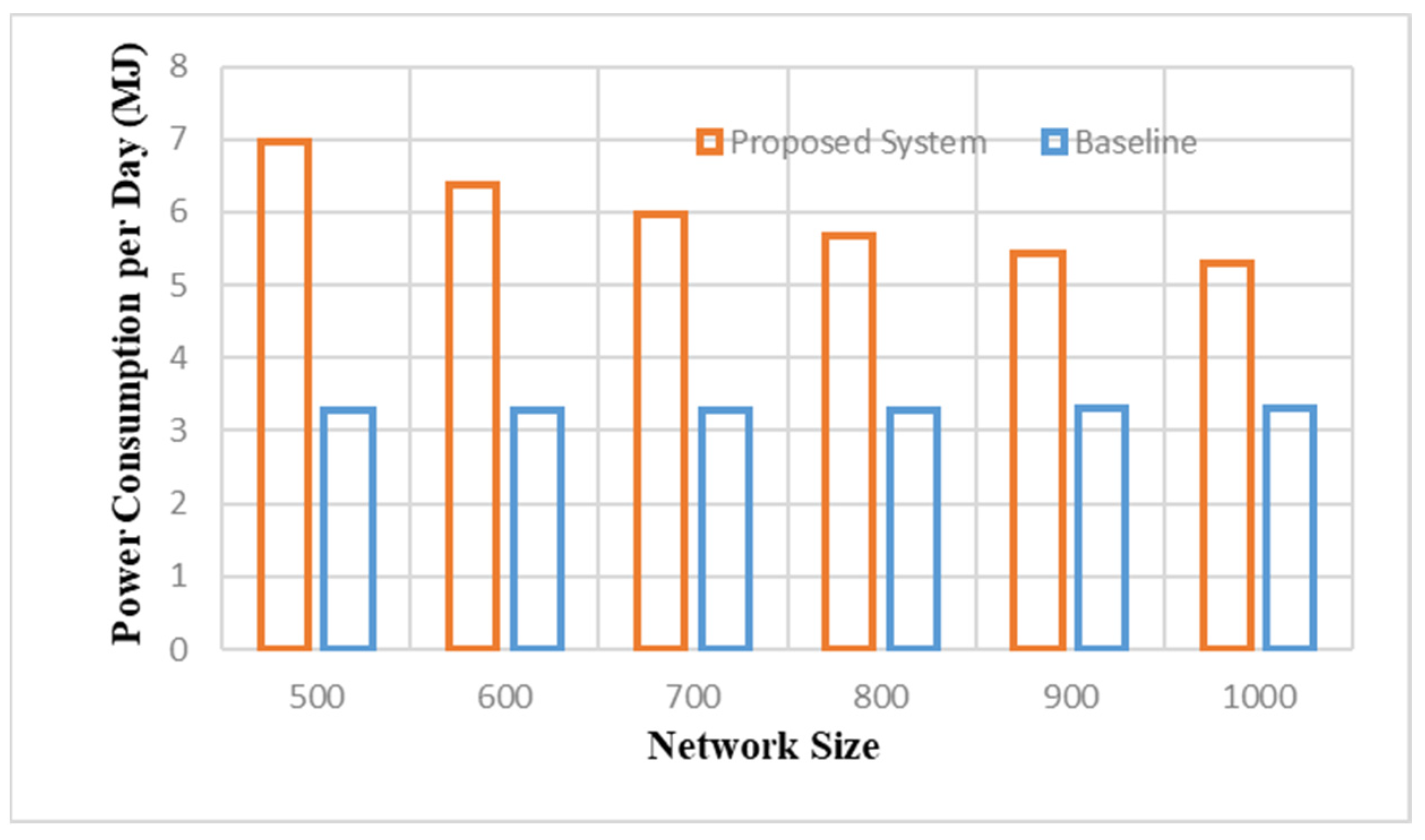
The performance of the proposed system is comprehensively evaluated using a network simulator. The result indicates the ability of the proposed system to increase network coverage while maintaining traffic reliability. The proposed system outperformed the standard LoRaWAN as it achieved a better delivery rate. The protocol also demonstrated scalability since it yielded a good performance while network sizes were increased. However, as a cost for providing data reliability and coverage extension, the proposed system showed higher energy consumption compared to the baseline system. In future work, the power consumption by the proposed system needs further investigation and analysis to improve the proposal’s performance regarding power consumption. This may involve investigating the listening time by out-of-range devices and the forwarding mechanism in order to decrease the consumed power. In addition, the impact of the proposed system on the traffic delay will be further investigated.


