Abstract
The rapid development of mobile devices and wireless network technologies have made them indispensable. This has created a demand for faster networks and longer battery life. The assurance of a stable network service and the enhancement of network experiences for mobile devices is equally crucial to meeting these demands. To address these challenges, mobile devices employ various techniques to decrease power consumption when they connect to wireless networks. Moreover, enhancing the endurance of mobile devices to maintain stable network services is critical when using wireless networks. In this paper, we propose a dual-radio opportunistic network for energy efficiency (DRONEE)–exponential weight with priority-based on rate control (WPRC) method which can extend and enhance the DRONEE hybrid network. By leveraging fuzzy logic control (FLC) and quality of service (QoS), our proposed method effectively solves the weighting problem in the DRONEE–weight (DRONEE–W) method. Through efficient allocation of network resources within each cluster, we minimize resource wastage and maximize resource utilization. Simulation results demonstrate the superior performance of our DRONEE–WPRC method in terms of throughput, buffer size, delay time, and power consumption compared to other methods. Therefore, our proposed method achieves optimal network resource allocation and energy efficiency.
1. Introduction
The rapid development and advancement of mobile devices and wireless network technology have made them indispensable in daily life. Essentially, all social activities can be performed and coordinated through smartphones. These activities include social networking, browsing information, instant messaging, gaming, sending and receiving emails, and viewing the stock market. As a result, there has been a growing requirement for faster mobile networks and longer battery life [,]. This trend has led the way for the emergence of green communications and networks that can be satisfied by employing various approaches, such as utilizing energy harvesting technology [,,,], artificial intelligence employed for resource management [], leveraging renewable energy [], and reducing energy wastage []. Specifically, energy harvesting technology collects energy from energy sources such as wind, solar, kinetic, and radio frequency signals. Harvesting energy from radio frequency signals has sparked interest in these signals that can be used for energy harvesting and data transmission. By leveraging radio frequency energy harvesting technology, wireless sensors can be operated more efficiently [,]. Radio frequency energy harvesting technology is integrated with cognitive radio networks [,]. This has effectively solved spectrum shortage and insufficient energy through energy transmission and data transmission. Radio frequency energy harvesting technology is an important issue in wireless sensor networks. The overarching goal of green communications and networks is to reduce power consumption, minimize environmental damage, and promote a more sustainable information and communication technology ecosystem.
The performance of previous cellular networks was mostly focused on the distribution of traffic [,] and traffic pattern learning []. These technologies are mainly to increase the period when the mobile device can turn off the wireless network, such as when the smartphone is on standby or when there is no network signal. There is also literature suggesting a method of delaying data transmission when there is no wireless network signal, and then performing the transmission after the wireless network is connected. However, these methods have disadvantages, such as causing additional system delays, leading to real-time confusion, inflexible services, and the utilization of complex traffic estimation or aggregation of traffic statistics from different applications. The existing literature has not considered the simultaneous use of one or more wireless interfaces to improve energy consumption [,]. Although some documents use multiple wireless modules to improve performance, these methods primarily focus on coordinating the balance of multiple parallel connections, such as multipoint transmission, multiplayer games, and device to device communications []. This paper uses the concept of the wireless sensor network [,]. It employs clusters and cluster heads to transfer data. It combines long-term evolution (LTE) cellular networks and wireless fidelity (Wi-Fi) networks to propose a hybrid network that can fully utilize the resources of two network interfaces. Additionally, it incorporates a fuzzy logic control (FLC) algorithm to automatically determine the optimal timing for utilizing the hybrid network. This innovative approach enhances network speed and network quality so that it significantly reduces the power consumption of mobile devices.
The dual-radio opportunistic network for energy efficiency (DRONEE) hybrid network was proposed in []. In the DRONEE method, users are grouped into clusters, and a cluster head is selected to establish communication with the base station. The DRONEE method has various schemes. The DRONEE–weight (DRONEE–W) method is utilized for allocating network resources in LTE networks. These clusters are interconnected through a Wi-Fi network, and each cluster is responsible for transmitting data to the evolved node B (eNB) via the cluster head []. In the DRONEE–W method, the system selects the node within each cluster with the best communication quality as the cluster head and uses the weighted round-robin (WRR) scheduling method to allocate resources for ensuring traffic that it is appropriately allocated to each node in the cluster. However, there is a limitation of the DRONEE–W method, which is its exclusive reliance on cluster size for resource allocation. This disregards the network demands of individual users. Consequently, the DRONEE–W method may lead to uneven resource allocation across users, and this potentially affects overall network performance. To address this, this paper proposes the DRONEE–exponential weight with priority-based rate control (WPRC) method. It enhances the performances of the DRONEE–W method and extends its application. The DRONEE–WPRC method utilizes the FLC algorithm and quality of service (QoS) [,] mechanism to efficiently allocate network resources within each cluster. Our objective is to improve the DRONEE–W method by adjusting network speed and resource allocation through weight and priority-based approaches. This optimizes the utilization of network resources. The primary objective of this paper can enhance the user’s wireless network experience, promote energy efficiency, and extend the battery life of their devices.
This paper includes several sections. Section 2 provides a discussion of the relevant literature. In Section 3, we present the dual-radio opportunistic networking for energy efficiency-exponential weight with priority-based rate control (DRONEE–WPRC) method in detail. Section 4 focuses on the presentation of the simulation. Finally, in Section 5, we conclude the paper by summarizing the proposed method and its contributions.
2. Related Work
2.1. Dual-Radio Opportunistic Networking for Energy Efficiency (DRONEE)
The DRONEE [] method utilizes a cluster-based approach to group users together with each cluster appointing a cluster head that improves energy efficiency and optimizes the utilization of LTE cellular networks. The cluster head is responsible for communicating with the evolved eNB. The eNB is an LTE terminology referring to the LTE cellular network infrastructure that is commonly known as a base station. This cluster head ensures efficient data transmission and network access for all members within the cluster. Users are connected through an energy efficient secondary wireless interface, such as Wi-Fi networks. The cluster head is responsible for high power consumption LTE communication with the base station [,]. DRONEE method’s cluster-based formation enables lower power consumption and contributes to an overall improvement in energy efficiency. This is because the DRONEE method’s cluster head selection process is determined on a per-frame basis. Therefore, its scheduling strategy is channel-opportunistic. This paper focuses on improving the DRONEE–W method, which utilizes the WRR scheduling method. The architecture of the DRONEE method is illustrated in Figure 1.
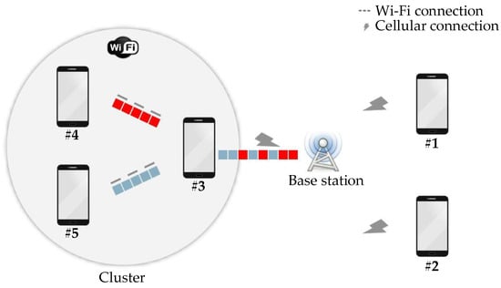
Figure 1.
Architecture of dual-radio opportunistic networking for energy efficiency (DRONEE).
In the cluster, the user with the best channel communication quality is selected to serve as the cluster head and is responsible for communicating with the base station. The DRONEE–W method emphasizes simplicity in its mechanisms. The complexity of throughput-fair opportunistic operations presents significant challenges for practical implementation in real systems []. Undoubtedly, pure opportunistic schedulers can be straightforward to implement and execute without requiring user cooperation. However, they often result in unfair behavior [].
The results of [] indicate that the DRONEE–W method can achieve high energy efficiency without sacrificing throughput fairness. Even when it employs a simple opportunistic mechanism. The DRONEE–W method simplifies scheduling complexity by allowing the base station to communicate only with the cluster head, since the base station only communicates with the cluster head and treats the cluster as a unit. The cluster members are scheduled based on their total traffic demand. From the perspective of model deployment, a cluster can be seen as a user within the cluster with the best base station connectivity. Under the DRONEE–W method, the base station plans multiple clusters for scheduling instead of counting individual users. This process indicates that the base station only provides the service to cluster, and the transmission is managed by the current cluster head.
2.2. Fuzzy Logical Control (FLC)
Since 1965, the FLC algorithm proposed by Zadeh, L. [] has been widely employed in various fields of technology, especially in wireless sensor networks [,,,,]. The FLC algorithm consists of four main components: fuzzification, fuzzy rules, fuzzy inference, and defuzzification. Fuzzification involves converting input parameter values into fuzzy logic and mapping them to their corresponding membership functions to determine the output membership degree. Fuzzy rules store all the potential rules of the input terminal, which are established based on experts’ experience or training from samples. Fuzzy inference occurs when the input parameter values satisfy one or more applicable rules. This process results in an appropriate output. Defuzzification is the process of converting the fuzzy inference result into an actual value that addresses the problem. For example, we consider an input terminal that is fuzzified to derive an output membership degree, which is then used to determine the output selection based on the fuzzy rules and fuzzy inference. Finally, defuzzification converts the fuzzy inference result into an exact value using methods such as the mean of maximum or center of gravity. The flowchart of the FLC algorithm is depicted in Figure 2.
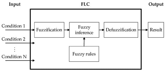
Figure 2.
Flowchart of fuzzy logic control.
3. Dual-Radio Opportunistic Networking for Energy Efficiency—Exponential Weight with Priority-Based Rate Control (DRONEE–WPRC)
After establishing a cluster, the DRONEE–W method assigns network resources to each cluster based on the weight of the cluster using the WRR scheduling method. To address the challenges associated with scheduling network resources for individual members of varying demand within the cluster, this paper proposes the DRONEE–WPRC method. Our proposed method incorporates a QoS mechanism [,] through FLC. We solve the WRR network resource scheduling problem described in Section 3.1.
In this section, we introduce the algorithm for improving the scheduling of network resources and propose the DRONEE–WPRC method. Our approach combines the FLC algorithm and weights to regulate the optimal transfer rate of the sink node. Additionally, our proposed method incorporates the priority-based rate control algorithm [] to determine the transmission rate of the aggregation node. By considering factors that the WRR scheduling method cannot address, our proposed method improves the efficiency of network resource scheduling. Consequently, all cluster members referred to as child nodes can fully utilize the network resources and lead to a reduction in delay time.
In each round of the DRONEE–WPRC method, a cluster head is selected, and the selected cluster head counts packet types for users within the cluster to allocate network resources accordingly. The packets are categorized into four types: video stream, audio, image, and text. The packets are prioritized in the same order as their categories. When there are multiple categories of packets to be transmitted, the category with the highest priority is processed first.
Initially, the cluster head acquires traffic based on the assigned weight and subsequently categorizes it according to the priority of the cluster members. The processed traffic is then transmitted back to the base station as information. At the base station, the total demand traffic and idle traffic for the round are consolidated, and the new weight for each cluster is calculated. This allows for the estimation of the optimal network resource allocation for the cluster in the next round. The overall workflow of the DRONEE–WPRC method is illustrated in Figure 3.
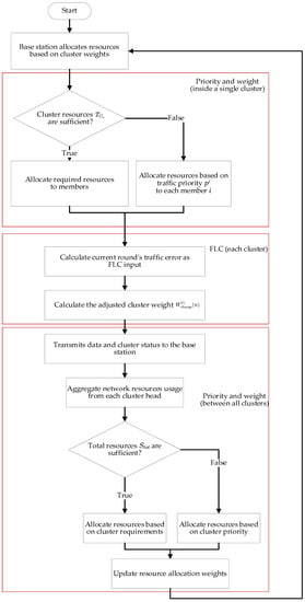
Figure 3.
Overall flow of the DRONEE–WPRC method.
3.1. Addressing Scheduling Problems and Proposing Improvements
In this section, we introduce the utilization of the QoS mechanism in the DRONEE–WPRC method to address the network resource scheduling problem in the DRONEE–W method. This problem is attributed to the limitations of the WRR scheduling method.
In the DRONEE method, the weight corresponds to each cluster . It can be assigned using various methods. In the case of the DRONEE–W method, weights are assigned based on the size of the cluster. The calculation of resource weights is determined as follows:
where represents the number of members in cluster and represents the number of all users under the network.
When the WRR scheduling method allocates all the upload resources, , within the frame, the average aggregate throughput and the average throughput of each user can be calculated using the equations described below.
In the DRONEE–W method, the average throughput received by cluster , is given as follows:
In the DRONEE–W method, the average throughput received by user , is given as follows:
In Equations (2) and (3), it can be observed that the cluster weight , which determines the average throughput received by the cluster is fixed and lacks flexibility. This limitation can lead to a problem where clusters with fewer members requiring more network resources are unable to acquire sufficient allocation. On the other hand, clusters with a larger number of members may have leftover network resources and lead to inefficient resource utilization and a suboptimal user experience. To address this issue, our proposed DRONEE–WPRC method introduces the QoS mechanism to optimize network resource allocation. When a cluster consistently utilizes network resources up to the allocated limit, the system examines the network resource usage of other clusters. If a cluster is found to have a lower usage rate and is unable to reach full utilization, the system adjusts the cluster weight accordingly, to ensure the effective utilization of network resources.
For example, let us consider cluster with three users and cluster with five users. According to the WRR scheduling method used in the DRONEE–W method, cluster . can allocate 37.5% of the total network resources , while cluster can allocate 62.5% of the total network resources . However, despite cluster having a larger number of members and being allocated more network resources, the five members within only utilize less than 20% of the allocated resources. Meanwhile, cluster which has fewer network resources, experiences congestion due to its resources being fully utilized. This scenario demonstrates that cluster consistently operates with a high load capacity, and the approximately 42.5% of the network resource is not effectively allocated by cluster . Therefore, the WRR scheduling method is used in the DRONEE–W method so that it may cause uneven network resource allocation in certain cases. This issue can lead to idle network resources and wastage. To address this issue, our proposed DRONEE–WPRC method leverages the QoS mechanism to dynamically adjust the cluster weights. Specifically, in this scenario, we increase the weight of cluster to increase the network resources that can allocate. This adjustment ensures that the resources of the entire network are effectively scheduled and utilized. We can optimize network performance and user experience. Figure 4 shows the DRONEE–W method problem scenario and our proposed solution.
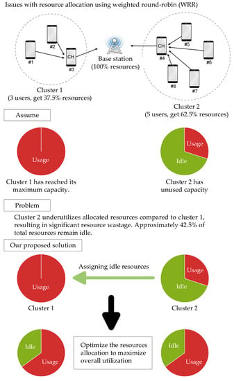
Figure 4.
Schematic of the DRONEE–W method problem scenario and our proposed solution.
3.2. Traffic Model Definition
We have defined four transmission types: the instant traffic transmission type and three types of non-instant traffic transmission. These transmission types are prioritized in the following order:
- Real-time (RT): this is the highest priority transmission type for instant, delay-sensitive traffic such as streaming video and telephony;
- High-priority nonreal time (HNRT): this is the secondary priority and typically used for transmitting non-instant traffic like audio;
- Medium-priority nonreal time (MNRT): This is the third priority and typically used for transmitting non-instant traffic like images;
- Low-priority nonreal time (LNRT): This is the lowest priority and is usually transmitting non-important and delay-tolerant traffic, such as text messages, e-mail, and application updates.
Transmission types 2 to 4 are categorized as non-instant traffic transmission types. The transmission rate of a child node is adjusted by the data type and the priority of its geographical location. The variable represents the sum of the transmission rates of all child nodes transmitted to the aggregation node. As depicted in Figure 5, the proposed algorithm utilizes the FLC algorithm to estimate the output transmission amount according to the input transmission amount received by the aggregation node. The output transmission amount refers to the data transmitted from the aggregation node to the base station.
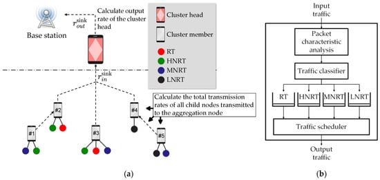
Figure 5.
The child node sends a packet queue (a) Schematic diagram of the traffic transfer model; (b) Packet classification queue model for each node.
The definitions of the maximum throughput and minimum delay achieved by the highest achievable transmission rate for each of the four transmission types are defined as follows:
where is the maximum throughput for the transmission type and is the allowable delay time for the transmission type.
Figure 5 depicts the child node utilizing a packet queue model. Each packet class is associated with a specific queue. When a packet enters the packet classifier, it undergoes analysis by the packet feature analyzer to determine its file type. According to its type, the packet data is assigned a priority weight. The transport traffic scheduler then handles the data based on its weight and prioritizing packet accordingly.
3.3. Weight Based on Priority-Based Rate Control
The weights discussed in [] are based on the priority-based rate control algorithm. Additionally, the adjusting transmission rate method is proposed in [], which combines the FLC algorithm and QoS mechanism as previously mentioned and is referred to as the exponential weight with priority-based on rate control (WPRC) algorithm. The WPRC algorithm employs a weight parameter to adjust the transmission rate of the aggregation node. By assigning traffic type and geographic location priorities to the child nodes, it enables a balance between network transmission and topology transmission rates. This balancing of the network transmission and topology transmission rates helps achieve control over network congestion.
3.4. FLC Model of the DRONEE–WPRC Method
Figure 6 illustrates the block diagram of the DRONEE–WPRC rate controller, which incorporates the FLC and WPRC algorithm. In the introduced FLC model, there are two input values and one output value. The input values, error () and error variation (), represent the difference between the input transmission rate and the output transmission rate . The output value serves as the weight parameter.
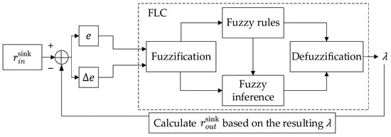
Figure 6.
Block diagram of the DRONEE–WPRC rate controller.
The FLC algorithm consists of four parts: fuzzification, fuzzy inference, fuzzy rule, and defuzzification. Fuzzification involves converting input parameter values into fuzzy logic and mapping them to their corresponding membership functions to determine the output membership degree. Fuzzy rules store all potential rules of the input. Fuzzy inference occurs when the input parameter value satisfies one or more applicable rules and results in an appropriate output. Defuzzification is the process of converting the result of the fuzzy inference into an exact value that addresses the problem.
In our introduced FLC model, the input variable value consists of seven membership functions: large positive (LP), medium positive (MP), small positive (SP), zero (Z), small negative (SN), medium negative (MN), and large negative (LN). The output value part includes seven membership functions: extremely low (EL), very low (VL), low (L), medium (M), high (H), very high (VH), and extremely high (EH). Figure 7 illustrates the membership functions for both input and output values. Table 1 presents the fuzzy rule set, which defines the actions of the entire FLC system.
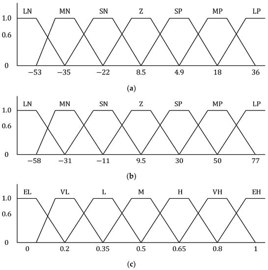
Figure 7.
Membership function graph for the DRONEE–WPRC fuzzy set (a) Transmission rate error (); (b) Error variation (); (c) Output weight parameter ().

Table 1.
Fuzzy rules for the DRONEE–WPRC method.
In the defuzzification part, the fuzzy inference result can be transformed into an exact value by defuzzification using the centroid method, which is depicted as follows:
where is the collection group of the fuzzy inference result, is the union in the entire set, and is a membership function of .
Section 3.3 and Figure 6 describe the utilization of the WPRC algorithm [] and the FLC model in the DRONEE–WPRC method to regulate the correlation of the output transmission rate at the aggregation node. However, in the WPRC algorithm, the weight parameter is fixed. This can lead to suboptimal network performance if there is a significant change in the transmitted data and results in a large error value between and . To address this issue, the DRONEE–WPRC method incorporates the FLC algorithm to dynamically adjust the weight parameter of the WPRC algorithm with the variations in transmitted data. This enables the sink node to achieve an optimal . Additionally, the DRONEE–WPRC method leverages the priority that it can assign to each child node to adjust the transmission rate.
Figure 8 illustrates the congestion control unit of the DRONEE–WPRC method. After the input rate is calculated by the congestion detection unit to determine and , the rate controller and rate management unit then adjust the output transmission rate based on these values. The process of adjusting the output transmission rate results in a new rate adjustment rate. The base station is responsible for aggregate nodes, while the sink node handles all child nodes.
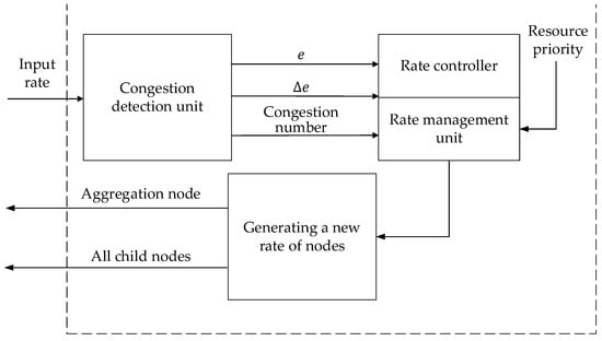
Figure 8.
DRONEE–WPRC congestion control unit architecture diagram.
In the DRONEE–WPRC method, each node is assigned a traffic priority . The traffic priority of node is represented by the resource priority . The priority levels of resource priority can also be manually configured to satisfy the personalized service. A higher value of indicates a higher traffic level. When transmitting data, the default subnode is assigned a traffic class if it contains a specific packet type, as mentioned in Section 3.2. Flow priority can be derived from Equation (4), and it is expressed as follows:
where is the traffic category which belongs to {RT, HNRT, MNRT, LNRT}.
The transmission rate calculation method can be divided into three steps as follows:
- Calculating and balancing the rate at the FLC output from the sink node between clusters;
- Calculating the transmission output by the new child node;
- Calculating the transmission output by the new aggregation node.
3.4.1. Calculating and Balancing the Rate at the FLC Output from the Sink Node between Clusters
We employ the FLC adjustment parameter to incorporate the error and error variation as input parameters. The error represents the difference between and at time , and it is expressed as:
The term represents the consecutive difference in error at time . It is given by:
According to Equation (8), when the error value of a cluster is positive, it indicates that the cluster is fully utilizing the resources. The network resource usage within the cluster is high load when it results in network congestion and limits network speeds. On the other hand, when the error value of a cluster is negative, the resource usage of the cluster has not reached full capacity and the resources are underutilized.
To determine the idle resource flow and demand flow of all current clusters, we first calculate the error value collected by the current base station from the cluster endpoints. According to the positive or negative values of the error value , we can determine the respective idle resource flow and demand flow by the following equations:
where represents the error value of the cluster, denotes the total sum of idle resource flows available for the round, represents the cluster among all clusters, where , and is the number of all clusters under the base station, as expressed in Equation (9). represents the sum of resource flows required for the round demand, represents the cluster among all clusters, where , and is the number of clusters under the base station.
The set represents the collection of child nodes belonging to node . The global priority for each node can be calculated using Equation (11). If no other child nodes exist in the node, the global priority is equal to .
where represents the aggregate of global priorities assigned to the sink nodes, denotes the set comprising all the subcollections and their respective sink nodes, and represents the sum of their priorities, which can be calculated by the following equation:
When we determine the sum of available idle resource traffic and required resource flow through Equations (9) and (10), respectively, we can readjust the allocation of resource flow from the base station to the cluster head. If is greater than , the currently idle network traffic is sufficient for the clusters that require network traffic. However, if is less than , it indicates that the current network traffic cannot allocate enough resources to the clusters requiring traffic adequately. In such cases, adjustments must be made to allocate network traffic appropriately in terms of need for the clusters.
Through Equation (12), we can calculate the sum of priority for each cluster after applying the DRONEE–WPRC method. When the available idle network resources cannot be fully allocated to all clusters requiring resources, the cluster traffic priority is used to determine the allocation ratio that also achieves a more equitable allocation of network resources. Clusters requiring resources receive the appropriate traffic allocation. The new weight distribution equation for cluster that requires network resource traffic is expressed as follows:
where is the adjusted weight of cluster in the round, with and is the total number of clusters under the base station, the term represents all the users in the network, denotes the number of members within cluster , is expressed as the weight parameter of cluster for the round, which is calculated from the aforementioned FLC model, the term represents the priority value of resource cluster . represents the cluster among all the required resource clusters, with and is the total number of resource clusters under the base station, the term represents the sum of the idle resource flows available for the round, the term represents the sum of the resource flows required for the round, and represents the total network resources.
In the DRONEE–WPRC method, the error value is generated according to each cluster collected by the base station. Equation (8) is used to determine whether the current network resources of the cluster efficiently handle the usage rate or if additional network traffic is required. Using Equations (9) and (10), we can calculate the total available network traffic and the total amount of demand traffic for all current clusters. Then, we can adjust the weight allocation from the base station to the cluster head using Equation (13). A cluster with a negative error value indicates that the cluster requires low network traffic. Thus, an adjusted weight that reduces the cluster’s allocation should be provided. A cluster with a positive error value indicates that the traffic allocated for the cluster is insufficient and that additional traffic allocation must be allocated. Using Equations (9) and (10), we determine the sum of the available idle traffic and the required traffic . We can determine whether the available network traffic is adequately allocated to the required clusters under the entire network topology and whether the available network traffic is sufficient for the clusters to be allocated according to demand. The error value is calculated by Equation (7) that it is allocated according to the demand clusters based on their respective traffic requirements. According to the demand flow, the weight of the demand cluster is increased. If the available network traffic is insufficient to be allocated to the demand cluster, then the priority is calculated by Equation (12) which is used to allocate traffic among the demand clusters. Weights are scaled according to the sum of priority values for all demand clusters. These scaled weights are then distributed to the demand clusters. This process enables the clusters that require network resources to obtain an appropriate amount of traffic. The process flowchart is illustrated in Figure 9.
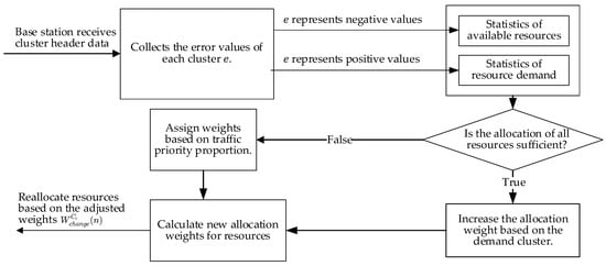
Figure 9.
Base station resource scheduling flowchart.
The flow equation estimated by each cluster is expressed as follows:
where represents the cluster head output rate for cluster in the round, denotes the new adjusted weight calculated according to Equation (13), , where denotes the total number of clusters under the base station, and represents all available network resources.
3.4.2. Calculating the Transmission Output by the New Child Node
To calculate the optimal transmission rate of node , the transmission rate of the base station is determined. Transmission from the aggregation node to node is according to the global priority of the child node and the proportion of the global priority of the sink node. This relationship can be represented by the following equation:
3.4.3. Calculating the Transmission Output by the New Aggregation Node
We define as the input transmission rate of node , which can be calculated by summing the output rates of all the child nodes. The equation for calculating is as follows:
where is the set of child nodes of node and represents the output rate of the child of node .
The transmission rate difference of node is calculated as follows:
where is a constant between 0 and 1.
The new output transmission rate for each child node generated by is calculated as follows:
In summary, our proposed DRONEE–WPRC method obtains traffic allocation based on the weight adjustment of the cluster head. Then, it evaluates whether sufficient traffic is available. If there is insufficient traffic, our proposed method allocates the traffic according to the traffic priorities to achieve optimal resource allocation.
4. Simulation Results
The simulation compared three methods: the proportional fair (PF) allocation [] method, the DRONEE–W [] method, and our proposed DRONEE–WPRC method. The PF allocation method is an algorithm that considers both throughput and fairness. It calculates the maximum rate that a user is allowed to use instantly. It is calculated by the ratio of instantaneous throughput to average throughput.
4.1. Network Performances
We compared the performance of these methods in terms of throughput, buffer size, and delay time in each round. The throughput was defined as the cumulative amount of data transmitted by all users to the base station per round. The buffer size refers to the total amount of data that each user cannot transmit to the base station per round. The delay time was defined as either the inability to transfer a certain amount of data to the base station within each round or it took a long time to complete the transfer to the base station [,]. Figure 10 provides a diagram illustrating the definition of buffer size and delay time.
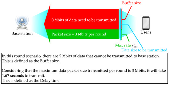
Figure 10.
Definition diagram for the buffer size and delay time.
The simulation parameters are set as in Table 2. The simulation was performed using MATLAB 9.14 and PHP 7.4.33. The data and figures represent the average results obtained from 500 simulations. The simulation was defined as having 100 rounds. The number of users was fixed at 30 people and users were randomly distributed in the field.

Table 2.
Parameters for the DRONEE–WPRC method simulation.
The simulation operators of the experiment divided users into groups according to their network usage rate. The users were divided into three groups: high-flow users, general traffic users, and low-traffic users. In the simulation, the definition of high-flow users was based on the RT and HNRT traffic transmission types. The file capacity of the transmission was 100 to 150% of the random simulation of the transmission packet. The definition of general traffic users was based on the MNRT traffic transmission type. The file capacity of the transmission was 75 to 100% of the random simulation of the transmission packet. The definition of low-traffic users was based on the LNRT traffic transmission type, and the file capacity of the transmission was 50 to 75% of the random simulation of the transmission packet. The network usage of each user was random according to the aforementioned traffic level. The simulated environment was a scenario in which the three groups of users were evenly distributed. The Wi-Fi transmission rate was set to , which is a reasonable rate according to the 802.11 a/g standard specification [,].
Figure 11 illustrates an example of the cluster formation diagram. In our simulation, we sequentially generated 30 users at random positions within the field. During the cluster formation process, we iterated through all the users and examined their nearby users so that it can establish a stable Wi-Fi connection based on their proximity to each other. These users are then grouped together in the same cluster. Finally, we iterate through each cluster and identify the user with the strongest LTE connection within the cluster, which corresponds to the user closest to the base station. Through this process, we have completed the cluster formation for the 30 users.
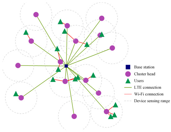
Figure 11.
Example diagram of the cluster formation.
Figure 12 illustrates the total throughput results for the scenario where the three groups of users were evenly distributed. Simulation results indicate that the overall average of total throughput for the DRONEE–WPRC, DRONEE–W, and PF methods are 98.17 Mbps, 85.46 Mbps, and 72.77 Mbps, respectively. The clustering architecture employed by the DRONEE–WPRC and DRONEE–W methods improves the total throughput compared to the PF method. Furthermore, our proposed DRONEE–WPRC method demonstrates high efficiency in resource allocation through the implementation of QoS-based resource scheduling. As a result, the total throughput of our proposed method surpasses that of the DRONEE–W method and PF method.
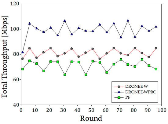
Figure 12.
Comparison of three methods for total throughput (Mbps).
Figure 13 illustrates the buffer size results for the scenario where the three groups of users were evenly distributed. The simulation result indicates that the overall average of the buffer size for the DRONEE–WPRC, DRONEE–W, and PF methods are 27.36 Mbits, 14.48 Mbits, and 39.20 Mbits, respectively. The adoption of the FLC algorithm and QoS mechanism for resource allocation and scheduling in our proposed DRONEE–WPRC method improves resource utilization compared to the DRONEE–W method and PF method. As a result, the overall buffer size of our proposed DRONEE–WPRC method is significantly reduced.
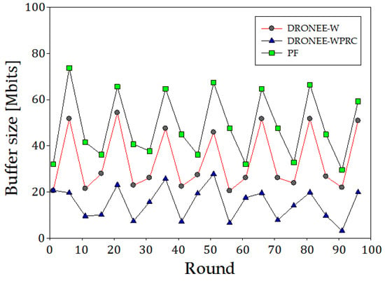
Figure 13.
Comparison of three methods for buffer size (Mbits).
Figure 14 illustrates the delay time results for the scenario where the three groups of users were evenly distributed. Simulation results indicate that the overall average of delay time for DRONEE–WPRC, DRONEE–W, and PF methods were 2.07 s, 5.84 s, and 19.88 s, respectively. The clustering architecture employed by the DRONEE–WPRC and DRONEE–W methods improves the total throughput compared to the PF method. Furthermore, the adoption of the FLC algorithm and QoS scheduling methods in our proposed DRONEE–WPRC method allows for better utilization of the network resources. This leads to a reduced buffer size and a corresponding reduction in delay time for users. As a result, the delay time of our proposed method surpasses that of the DRONEE–W method and PF method.
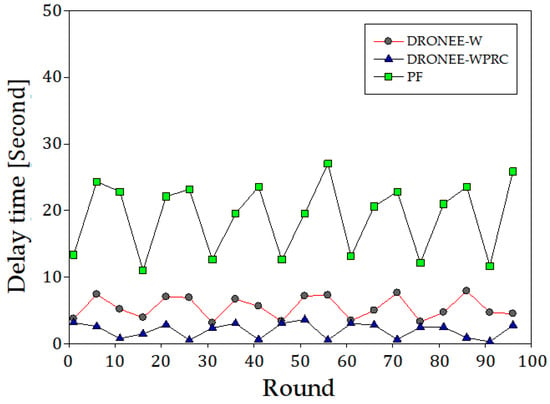
Figure 14.
Comparison of three methods for delay time (Second).
4.2. Network Power Consumption
We collected the average remaining battery for all users over various rounds in the simulation field at the end of each round for the scenario where three groups of users were evenly distributed. The simulation parameters were set according to Table 3. The number of users was 30 and the initial battery capacity of users was 100 mAh with an operating voltage of 3.7 V. In each round, users are required to transmit a packet of size 1024 KB. According to [,], the power consumption per Mbps of LTE uplink is 438.39 mW, Wi-Fi transmission is 283.17 mW, and Wi-Fi reception is 137.01 mW.

Table 3.
Parameters for the power consumption simulation.
Figure 15 illustrates the average remaining battery results in a scenario where three groups of users were evenly distributed. The simulation result indicates that the number of rounds until the battery depleted for the DRONEE–WPRC, DRONEE–W, and PF methods were 310, 309, and 193, respectively. The clustering architecture employed by the DRONEE–WPRC and DRONEE–W methods leverages the lower power consumption of the Wi-Fi network. As a result, users can utilize less power while efficiently meeting their network requirements.
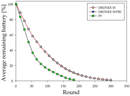
Figure 15.
Comparison of three methods for average remaining battery.
In summary, we have conducted simulations in the scenario where three groups of users were evenly distributed to evaluate our proposed DRONEE–WPRC method. Simulation results show that the total throughput of our proposed DRONEE–WPRC method is 14.87% and 34.9% higher than DRONEE–W and PF methods, respectively. The buffer size of our proposed DRONEE–WPRC method is 47.07% and is 63.06% lower than the DRONEE–W and PF methods, respectively. The delay time of our proposed DRONEE–WPRC method is 64.55% and is 89.58% lower than the DRONEE–W and PF methods, respectively. The power consumption of our proposed DRONEE–WPRC method is 60.62% lower than the PF method. The power consumption of our proposed DRONEE–WPRC and DRONEE–W methods were close. Our proposed DRONEE–WPRC method combines clustering architecture with the incorporation of the FLC algorithm and QoS mechanism. As a result, our proposed DRONEE–WPRC method demonstrates several advantages in terms of total throughput, buffer size, delay time, and power consumption.
5. Conclusions
In this paper, the DRONEE–WPRC method is proposed as an enhancement to the existing DRONEE–W method. By incorporating weights and priorities into the DRONEE–W method, our proposed method dynamically adjusts the network allocation using the base station. It considers the cluster and network packet type of the smartphone user to set traffic priorities and determine the weight for network resource allocation. Thereby, it addresses the weighting problem in the original DRONEE–W method and mitigates potential issues with the weighted round-robin scheduling method. Simulation results indicated that the total throughput of our proposed DRONEE–WPRC method is 14.87% and is 34.9% higher than the DRONEE–W and PF methods, respectively. The buffer size of our proposed DRONEE–WPRC method is 47.07% and is 63.06% lower than the DRONEE–W and PF methods, respectively. The delay time of our proposed DRONEE–WPRC method is 64.55% and is 89.58% lower than DRONEE–W and PF methods, respectively. The power consumption of our proposed DRONEE–WPRC method is 60.62% lower than PF method and close to the DRONEE–W method. The clustering feature utilized in both the DRONEE–W and DRONEE–WPRC methods significantly reduced network congestion and power consumption. In the proposed DRONEE–WPRC method, the incorporation of the FLC algorithm and QoS mechanism enabled the optimal utilization of network resources. Furthermore, it can reduce buffer size and delay time for users in the field. Our proposed DRONEE–WPRC method also improves energy efficiency.
Author Contributions
Conceptualization, Y.-L.C.; methodology, Y.-L.C. and N.-C.W.; software, Y.-S.L. and C.-Y.K.; validation, Y.-S.L., N.-C.W. and C.-Y.K.; formal analysis, Y.-L.C. and N.-C.W.; investigation, N.-C.W. and Y.-S.L.; resources, N.-C.W. and Y.-L.C.; data curation, Y.-S.L. and C.-Y.K.; writing—original draft preparation, Y.-S.L., Y.-L.C. and C.-Y.K.; writing—review and editing, Y.-L.C. and C.-Y.K.; visualization, Y.-S.L. and C.-Y.K.; supervision, Y.-L.C.; project administration, Y.-L.C.; funding acquisition, Y.-L.C. All authors have read and agreed to the published version of the manuscript.
Funding
This work was supported by the Ministry of Science and Technology of the Republic of China under grant MOST-109-2221-E-025-008.
Institutional Review Board Statement
Not applicable.
Informed Consent Statement
Not applicable.
Data Availability Statement
Not applicable.
Conflicts of Interest
The authors declare no conflict of interest.
References
- Xenakis, D.; Passas, N.; Merakos, L.; Verikoukis, C. Advanced mobility management for reduced interference and energy consumption in the two-tier LTE-advanced network. Comput. Netw. 2015, 76, 90–111. [Google Scholar] [CrossRef]
- Amour, L.; Dandoush, A. Crowdsourcing based performance analysis of mobile user heterogeneous services. Electronics 2022, 11, 1011. [Google Scholar] [CrossRef]
- Baranov, A.; Akbari, S.; Spirjakin, D.; Bragar, A.; Karelin, A. Feasibility of RF energy harvesting for wireless gas sensor nodes. Sens. Actuators A Phys. 2018, 275, 37–43. [Google Scholar] [CrossRef]
- Song, X.; Chin, K. Maximizing packets collection in wireless powered IoT networks with charge-or-data time slots. IEEE Trans. Cogn. Commun. Netw. 2023, 1. early access. [Google Scholar] [CrossRef]
- Liu, X.; Xu, B.; Wang, X.; Zheng, K.; Chi, K.; Tian, X. Impacts of sensing energy and data availability on throughput of energy harvesting cognitive radio networks. IEEE Trans. Veh. Technol. 2023, 72, 747–759. [Google Scholar] [CrossRef]
- Zheng, K.; Jia, X.; Chi, K.; Liu, X. DDPG-based joint time and energy management in ambient backscatter-assisted hybrid underlay CRNs. IEEE Trans. Commun. 2023, 71, 441–456. [Google Scholar] [CrossRef]
- Danino, T.; Ben, Y.; Greenberg, S. Container allocation in cloud environment using multi-agent deep reinforcement learning. Electronics 2023, 12, 2614. [Google Scholar] [CrossRef]
- Perin, G.; Meneghello, F.; Carli, R.; Schenato, L.; Rossi, M. EASE: Energy-aware job scheduling for vehicular edge networks with renewable energy resources. IEEE Trans. Green Commun. Netw. 2023, 7, 339–353. [Google Scholar] [CrossRef]
- Hussain, K.; Gupta, R. Method to minimize radio resource wastage and battery consumption in NB-IoT. In Proceedings of the IEEE Wireless Communications and Networking Conference, Nanjing, China, 29 March 2021. [Google Scholar]
- Balasubramanian, N.; Balasubramanian, A.; Venkataramani, A. Energy consumption in mobile phones: A measurement study and implications for network applications. In Proceedings of the IMC ‘09: Internet Measurement Conference, Chicago, IL, USA, 4–6 November 2009. [Google Scholar]
- Liu, H.; Zhang, Y.; Zhou, Y. TailTheft: Leveraging the wasted time for saving energy in cellular communications. In Proceedings of the MobiSys ‘11: The 9th International Conference on Mobile Systems, Applications, and Services, Bethesda, MD, USA, 28 June 2011. [Google Scholar]
- Deng, S.; Balakrishnan, H. Traffic-aware techniques to reduce 3G/LTE wireless energy consumption. In Proceedings of the CoNEXT ‘12: Conference on Emerging Networking Experiments and Technologies, Nice, France, 10–13 December 2012. [Google Scholar]
- Lee, K.; Lee, J.; Yi, Y.; Rhee, I.; Chong, S. Mobile data offloading: How much can WiFi deliver? IEEE/ACM Trans. Netw. 2013, 21, 536–550. [Google Scholar] [CrossRef]
- Ristanovic, N.; Boudec, J.; Chaintreau, A.; Erramilli, V. Energy efficient offloading of 3G networks. In Proceedings of the IEEE 8th International Conference on Mobile Ad-Hoc and Sensor Systems, Valencia, Spain, 17–22 October 2011. [Google Scholar]
- Lei, L.; Zhong, Z.; Lin, C.; Shen, X. Operator controlled device-to-device communications in LTE-advanced networks. IEEE Wirel. Commun. 2012, 19, 96–104. [Google Scholar] [CrossRef]
- Sergiou, C.; Vassiliou, V.; Paphitis, A. Congestion control in wireless sensor networks through dynamic alternative path selection. Comput. Netw. 2014, 75, 226–238. [Google Scholar] [CrossRef]
- Bagci, H.; Yazici, A. An energy aware fuzzy approach to unequal clustering in wireless sensor networks. Appl. Soft Comput. 2013, 13, 1741–1749. [Google Scholar] [CrossRef]
- Asadi, A.; Mancuso, V. DRONEE: Dual-radio opportunistic networking for energy efficiency. Comput. Commun. 2014, 50, 41–52. [Google Scholar] [CrossRef]
- Wang, Y.; Chuang, C. Efficient eNB deployment strategy for heterogeneous cells in 4G LTE systems. Comput. Netw. 2015, 79, 297–312. [Google Scholar] [CrossRef]
- Liu, T.; Wang, K.; Ku, C.; Hsu, Y. QoS-aware resource management for multimedia traffic report systems over LTE-A. Comput. Netw. 2016, 94, 375–389. [Google Scholar] [CrossRef]
- Sankar, V.; Sharma, V. QoS provisioning for multiple Femtocells via game theory. Comput. Netw. 2016, 102, 70–82. [Google Scholar] [CrossRef]
- Huang, J.; Quan, F.; Gerber, A.; Mao, Z.; Sen, S.; Spatscheck, O. A close examination of performance and power characteristics of 4G LTE networks. In Proceedings of the MobiSys ‘12: The 10th International Conference on Mobile Systems, Applications, and Services, Low Wood Bay, Lake District, UK, 25–29 June 2012. [Google Scholar]
- Garcia, A.; Serrano, P.; Banchs, A.; Bianchi, G. Energy consumption anatomy of 802.11 devices and its implication on modeling and design. In Proceedings of the CoNEXT ‘12: Conference on Emerging Networking Experiments and Technologies, Nice, France, 10–13 December 2012. [Google Scholar]
- Ramabhadran, S.; Pasquale, J. Stratified round robin: A low complexity packet scheduler with bandwidth fairness and bounded delay. In Proceedings of the SIGCOMM ‘03: Applications, Technologies, Architectures, and Protocols for Computer Communications, Karlsruhe, Germany, 25–29 August 2003. [Google Scholar]
- Asadi, A.; Mancuso, V. A survey on opportunistic scheduling in wireless communications. IEEE Commun. Surv. Tutor. 2013, 15, 1671–1688. [Google Scholar] [CrossRef]
- Zadeh, L. Fuzzy sets. Inf. Control. 1965, 8, 338–353. [Google Scholar] [CrossRef]
- Chen, Y.; Wang, J.; Lin, Y.; Wen, J. Combined fuzzy-based power control with window-based transmission rate management in multimedia CDMA cellular systems. AEU Int. J. Electron. Commun. 2011, 65, 377–383. [Google Scholar] [CrossRef]
- Mayer, K.; Oliveira, M.; Müller, C.; Castro, F.; Castro, M. Blind fuzzy adaptation step control for a concurrent neural network equalizer. Wirel. Commun. Mob. Comput. 2019, 2019, 9082362. [Google Scholar] [CrossRef]
- Thuy, N.; Wongthanavasu, S. Hybrid filter–wrapper attribute selection with alpha-level fuzzy rough sets. Expert Syst. Appl. 2022, 193, 116428. [Google Scholar] [CrossRef]
- Lee, J.; Cheng, W. Fuzzy-logic-based clustering approach for wireless sensor networks using energy predication. IEEE Sens. J. 2012, 12, 2891–2897. [Google Scholar] [CrossRef]
- Sattar, H.; Bajwa, I.; Amin, R.; Muhammad, J.; Mushtaq, M.; Kazmi, R.; Akram, M.; Ashraf, M.; Shafi, U. Smart wound hydration monitoring using biosensors and fuzzy inference system. Wirel. Commun. Mob. Comput. 2019, 2019, 8059629. [Google Scholar] [CrossRef]
- Yaghmaee, M.; Adjeroh, D. Priority-based rate control for service differentiation and congestion control in wireless multimedia sensor networks. Comput. Netw. 2009, 53, 1798–1811. [Google Scholar] [CrossRef]
- Chen, Y.; Lai, H. Priority-based transmission rate control with a fuzzy logical controller in wireless multimedia sensor networks. Comput. Math. Appl. 2012, 64, 688–698. [Google Scholar] [CrossRef]
- Chen, Y.; Lai, H. A fuzzy logical controller for traffic load parameter with priority-based rate in wireless multimedia sensor networks. Appl. Soft Comput. 2014, 14, 594–602. [Google Scholar] [CrossRef]
- Kushner, H.; Whiting, P. Convergence of proportional-fair sharing algorithms under general conditions. IEEE Trans. Wirel. Commun. 2004, 3, 1250–1259. [Google Scholar] [CrossRef]
- Zheng, Z.; Sinha, P. Buffer coding for reliable transmissions over wireless networks. Comput. Commun. 2009, 32, 111–123. [Google Scholar] [CrossRef]
- Rodas, A.; Llopis, L.; Igartua, M.; Gargallo, E. Dynamic buffer sizing for wireless devices via maximum entropy. Comput. Commun. 2014, 44, 44–58. [Google Scholar] [CrossRef]
- Jain, R.; Chiu, D.; Hawe, W. A Quantitative Measure of Fairness and Discrimination for Resource Allocation in Shared Computer System; Eastern Research Laboratory: Hudson, MA, USA, 1984. [Google Scholar]
- ETSI. LTE.; Evolved Universal Terrestrial Radio Access (E-UTRA); Medium Access Control (MAC) Protocol Specification (3GPP TS 36.321 Version 10.0.0 Release 10); ETSI TS 136 321 V10.0.0; ETSI: Sophia Antipolis, France, 2011. [Google Scholar]
Disclaimer/Publisher’s Note: The statements, opinions and data contained in all publications are solely those of the individual author(s) and contributor(s) and not of MDPI and/or the editor(s). MDPI and/or the editor(s) disclaim responsibility for any injury to people or property resulting from any ideas, methods, instructions or products referred to in the content. |
© 2023 by the authors. Licensee MDPI, Basel, Switzerland. This article is an open access article distributed under the terms and conditions of the Creative Commons Attribution (CC BY) license (https://creativecommons.org/licenses/by/4.0/).