Abstract
Multi-user multiple-input and multiple-output (MU-MIMO) systems are the mainstream of current antenna design. This paper proposes a dual-band 6 × 6 MIMO glasses antenna for Wi-Fi 6E and Wi-Fi 7 indoor wireless communication. The six antennas have the same structure, all of which are F-shaped monopole antennas. They are on the left and right temples, at the upper and lower ends of the left and right frames, which effectively uses the space of the glasses. The substrate uses FR4 . The antenna design is compact (9 mm × 50 mm × 0.8 mm) and the glasses model is made of FR4. The overall model is similar to virtual reality (VR) glasses, which are convenient for a user to wear. The proposed antenna has three working frequency bands, at 2.4 GHz, 5 GHz, and 6 GHz. Through matching and optimization, the reflection coefficient can be lower than −10 dB. In addition, this paper evaluates two usage environments for simulation and measurement on the head and free space. The measurement results show that when the operating frequency band is at 2.45 GHz, the antenna efficiency is 86.1%, and the antenna gain is 1.9 dB. At 5.5 GHz, the antenna efficiency is 86.5%, and the antenna gain is 4.4 dB. At 6.7 GHz, the antenna efficiency is 85.4%, and the antenna gain is 3.7 dB. When the isolation of the MIMO antenna system is optimized, the low-frequency band is better than −10 dB, and the high-frequency band is better than −20 dB. The measured envelope correlation coefficient (ECC) values are all lower than 0.1.
1. Introduction
Recently, wearable devices have become very popular in consumer electronics and biomedical applications. There are various wearable devices, such as smart bracelets, smart rings, smart gloves, smart glasses, and other devices. These wearable devices have in common that they are thin, light, and ergonomic. With antenna design optimization, communication modulation in wearable devices has gradually evolved from Wi-Fi indoor technology to 4G cellular network and 5G mm wave beamforming. More and more companies are developing smart glasses products like those of Google and Facebook. In the next generation, the popularization of intelligent wearable devices will significantly improve people’s living habits [1,2,3,4].
In order to realize the application of multi-band antennas in intelligent wearable devices and small-sized mobile phones, the development of small multi-band antennas has become a challenge faced by antenna design, and microstrip monopole antennas are one of the mainstream design structures for small multi-band antennas. Because of their ease of production and good microstrip antenna performance, they have received a great deal of attention and been the subject of vigorous development in recent years [5,6,7,8,9,10]. For example, the meandering structure of the antenna reduces the size of the antenna. Furthermore, this small-sized antenna is able to be applied in wearable devices that use the WBAN operating band, including 2.4 GHz and 5 GHz [5]. Alternatively, small-sized antennas can be applied in smartwatches that work in the Wi-Fi band, with an antenna efficiency that can reach 50% [6].
The advantage of monopole antennas is that they can be applied in different types of wireless communication technologies, including 4G LTE, 5G mm Wave, BT, GPS, WiMAX, and Wi-Fi 6E, with high efficiency and high gain [11,12,13,14,15]. In Ref. [11], a monopole antenna was applied to LTE 700/2500 and GSM 850/900/1800/1900, and the UMTS2100 antenna gain reached 6 dB. In Ref. [12], the antenna bands employed were 5G, Wi-Fi, and WiMAX.
In the past, indoor Wi-Fi communication has used the 2.4 GHz and 5 GHz bands, but in 2020, the Wi-Fi Alliance proposed a next-generation Wi-Fi communication technology, namely, Wi-Fi 6E [16]. It works in the newly licensed 6 GHz band and uses the new modulation 802.11 ax to deliver a throughput that is 2.7 times faster than 802.11 ac. In addition, Wi-Fi 6E is downward compatible, so the working frequency band includes 2.4 GHz, 5 GHz, and 6 GHz [17].
Wearable devices need to be very close to different parts of the human body. Therefore, it is necessary to evaluate the specific absorption rating (SAR) [18,19]. The SAR value must meet different specifications, depending on the regulations in different countries. Common SAR value specifications are 1 g 1.6 W/kg [20] and 10 g 2 W/kg [21]. When the working frequency exceeds 6 GHz, in addition to the evaluating of SAR value, it is also necessary to test the power density (PD), and the regulatory standard for PD is 10 W/m2 [22].
There have been many studies on wearable devices, but these have rarely discussed smart glasses. In this article, a 6 × 6 MIMO antenna system is proposed for application in eyewear devices. Section 2 describes the F-shaped monopole antenna design process and simulates it. Section 3 discusses the influence of the glasses antennas when placed near the human head, and provides the head SAR simulation. In Section 4, the glasses antenna is produced according to the previous simulation results, and a far-field test is performed in a far-field chamber to obtain the 2D radiation pattern, antenna gain, and antenna efficiency. Finally, the proposed antenna is compared with other reference antennas. The conclusions of the article are presented in Section 5.
2. Design Process
Figure 1a shows the structure of the 6 × 6 MIMO monopole antenna system applied to the Wi-Fi 6E band proposed in this paper. Moreover, the six antennas are distributed on the upper and lower frames and temples. The antenna is engraved on the glass fiber (FR4) plate, the substrate thickness is 0.8 mm, the dielectric constant is 4.4, and the dielectric loss coefficient is 0.02. All of the antennas were F-shaped monopole antennas, whereby the monopole antenna can be bent at an angle of 90 degrees to reduce antenna length and area while still maintaining a quarter wavelength resonance.
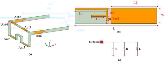
Figure 1.
(a) The proposed 6 × 6 MIMO glasses antenna; (b) F-shaped monopole antenna detailed dimensions; (c) equivalent model of the proposed antenna.
As presented in Figure 1a, the structure of glasses is similar to that of lightweight VR glasses, and the total size of the glasses is 155 mm × 145 mm × 50 mm. Antenna 1 is arranged on the left temple, antenna 3 and antenna 5 are arranged on the upper left and lower left frame, antenna 2 is arranged on the right temple, and antenna 4 and antenna 6 are also arranged on the upper frame and lower frame. The overall architecture of the glasses is symmetrical. Figure 1b presents the dimensions of a single antenna. From the direction of the feed point, the antenna is an F-shaped monopole antenna, and Table 1 provides detailed dimensions. The volume of a single antenna is 50 mm × 9 mm × 0.8 mm. Figure 1c presents an equivalent model of the proposed antenna. When it is configured on the frame of the glasses, as shown in Figure 1a, the 6 × 6 MIMO glasses antenna will be very compact.

Table 1.
Proposed antenna dimensions.
2.1. Simulation and Analysis
Figure 2 shows the proposed antenna design steps; in this article, the electromagnetic simulation software High-Frequency Structure Simulator (HFSS) 2021R1 was used for simulation. The 2.4 GHz band is first designed in Figure 2a to satisfy the wide bandwidth of the antenna in the 5–7 GHz band. Then, the authors tried four antennas to increase the high-frequency bandwidth, and recorded the antenna formation process, as shown in Figure 2a. The first antenna type subtracts a part of the metal ground plane. The reflection coefficient in Figure 2b shows that the reflection coefficient of the antenna type 1 in the 5–7 GHz band does not reach −10 dB. Antenna type 2 fills the metal ground plane. The reflection coefficient in Figure 2b shows that the reflection coefficient of antenna type 2 in the 5–7 GHz frequency band reaches −10 dB at 6.1–6.3 GHz, but the bandwidth ratio is only 12.5%, which is not enough to cover the Wi-Fi 6E band. The third antenna type moves the main antenna structure away from the metal ground plane, and the reflection coefficient in the 5.6–7.1 GHz band reaches −10 dB, and the bandwidth ratio increases to 47%. Finally, the antenna type published in this article adjusts the 5 GHz radiator to the middle to form an antenna structure with an inverse F shape. As a result, the reflection coefficient of its high-frequency broadband in the range 5.1–7.2 GHz is lower than −10 dB, and the overall antenna resonance frequency band covers the Wi-Fi 6E bands.
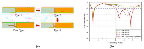
Figure 2.
(a) Antenna design process; (b) S-parameter results of the antenna design process.
Next, path analysis of the antenna at low and high frequencies is performed. The reflection coefficient in Figure 3a shows that reducing the length of L1 shifts the resonance of 2.4 GHz and 6 GHz to high frequencies. The reflection coefficient in Figure 3b shows that reducing the length of L3 shifts the resonance of 5 GHz to high frequencies. The simulation results show that the antenna operating frequency band is generated by L1 and L3.
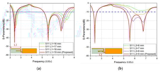
Figure 3.
Antenna patch analysis: (a) 2.4 GHz path analysis; (b) 5 GHz path analysis.
2.2. Surface Current and E Field Analysis
Observation of the surface current and the E field simulation results under different frequencies through HFSS, with working frequencies of 2.45 GHz, 5.5 GHz and 6.7 GHz, are shown in Figure 4. When both the surface current and the E field are strong, they are represented by red blocks and arrows; otherwise, they are blue. The surface current and E field at 2.45 GHz, the low-frequency of antenna is radiated by branch L1. The surface current and E field at 5.5 GHz, the high-frequency of antenna is radiated by branch L3. The surface current and E Field at 6.7 GHz, from coupling between branch W1 and ground plane.
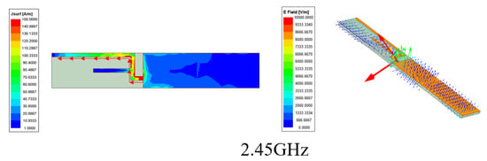
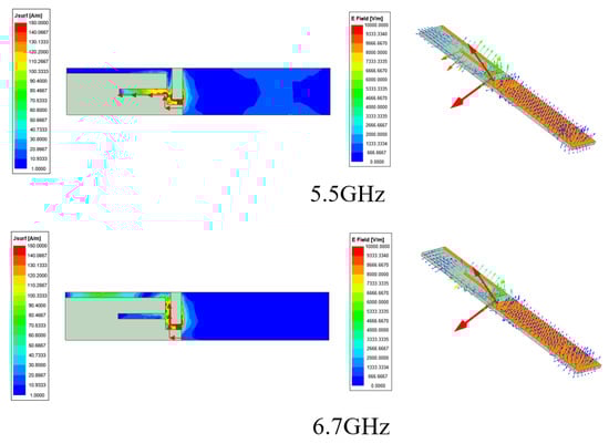
Figure 4.
Surface current and E field simulation results at 2.45 GHz, 5.5 GHz, 6.7 GHz.
3. Human Head Simulation and Analysis
For people who need to wear glasses, the time spent with glasses on their head may account for more than two-thirds of their day, resulting in light weight and comfort being among the development goals of smart glasses. The planar antenna proposed in this paper was designed on a lightweight FR4 substrate, with a combined thickness and weight similar to those of commercially available glasses. Therefore, this structure will be used to explore the impact of electromagnetic radiation on the human body.
When the glasses antenna is situated close to the human head, the characteristics of the antenna will be affected. This is because the human body is a high-loss medium. It is necessary to evaluate the characteristics of the antenna when it is close to the human head. Sim4Life was used to simulate the values of SAR and PD, allowing the antenna proposed in this paper to be closer to life. Figure 5 shows the proposed glasses antenna worn on a model of a human head using the Sim4Life simulation software.
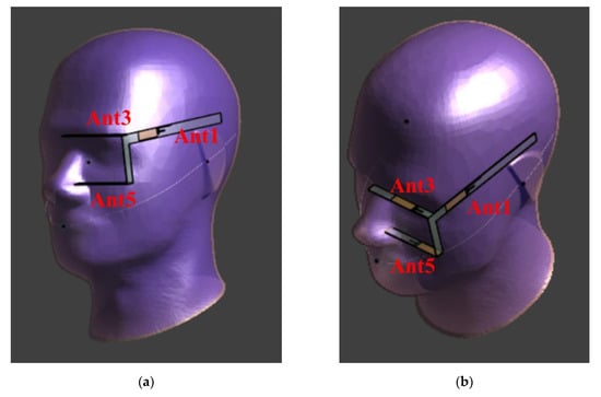
Figure 5.
Glasses antenna placed on a head model. (a) Right view; (b) top view.
Next, the simulation results of the antenna when worn on the head are presented. The proposed glasses antenna possesses a symmetrical structure; therefore, only the three antennas on the left side of the glasses—Ant1, Ant3, and Ant5—will be employed to simulate reflection coefficient, isolation, SAR, and PD. The reflection coefficient in Figure 6a shows that when the antenna is situated close to the human head, the resonance bands of Ant1 at 5 GHz and 6 GHz shift slightly towards a lower band. Meanwhile, when Ant3 and Ant5 are situated close to the human head, the resonance in the 5 GHz band weakens, and the 6 GHz frequency band shifts to a lower frequency; however, the overall bandwidth and resonance band are able to meet the requirements of Wi-Fi6e applications. Figure 6b shows the isolation of the three antennas. It can be observed that the isolation values of S13 and S15 are lower than −20 dB at 2.4 GHz, 5 GHz, and 6 GHz. The isolation value of S35 at 2.4 GHz is only −12 dB, but lower than −20 dB at 5 GHz and 6 GHz.
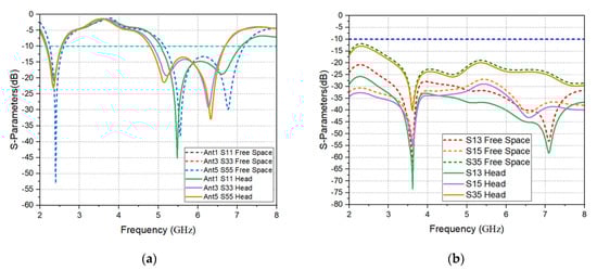
Figure 6.
Glasses antenna simulation on a human head and in free space: (a) reflection coefficients of antenna 1, antenna 3, and antenna 5; (b) isolation of antenna 1, antenna 3, and antenna 5.
Wearable devices must be close to the human body when in use, where they will transmit data by antennas, and electromagnetic waves will be irradiated during the transmission of data. Therefore, most countries have formulated standards and regulations in order to limit electromagnetic radiation exposure. If these standards and regulations are not followed in order to comply with national regulations, a product will be restricted from entering the market. The regulations of most countries are based on the values stated by the Federal Communications Commission (FCC) of 1 g SAR 1.6 W/kg and 10 g SAR 2 W/kg in the European CE. The following equation [21] is the method for calculating SAR, and this equation is defined as the radiation power energy absorbed by a unit volume in a specific time:
The 6 × 6 glasses antennas proposed in this paper sit close to the human head. The SAR simulation was carried out using the Sim4Life simulation software. When the distance of the glasses antenna from the human head is 10 mm, and the input power is 0.1 W (20 dBm), the frequencies of the three antennas are set to 2.45 GHz, 5.5 GHz, and 6.7 GHz to calculate the 1 g SAR and 10 g SAR values. According to the simulation results in Figure 7, it can be observed that the 1 g SAR and 10 g SAR values of antenna 1 at 2.4 GHz are 0.727 W/kg and 0.493 W/kg, respectively; the 1 g SAR and 10 g SAR values at 5.5 GHz are 0.938 W/kg and 0.433 W/kg, respectively; and the 1 g SAR and 10 g SAR values at 6.7 GHz are 1.55 W/kg and 0.796 W/kg, respectively. Furthermore, from the simulation results in Figure 8, it can be seen that the 1 g SAR and 10 g SAR values of antenna 3 at 2.4 GHz are 1.18 W/kg and 0.674 W/kg, respectively; the 1 g SAR and 10 g SAR values at 5.5 GHz are 1.13W/kg and 0.457 W/kg, respectively; and the 1 g SAR and 10 g SAR values at 6.7 GHz are 0.18 W/kg and 0.869 W/kg, respectively. Finally, from the simulation results in Figure 9, it can be seen that the 1 g SAR and 10 g SAR values of antenna 5 at 2.4 GHz are 0.434 W/kg and 0.26 W/kg, respectively; the 1 g SAR and 10 g SAR values at 5.5 GHz are 0.256 W/kg and 0.145 W/kg, respectively; and the 1 g SAR and 10 g SAR values at 6.7 GHz are 0.931 W/kg and 0.468 W/kg, respectively.
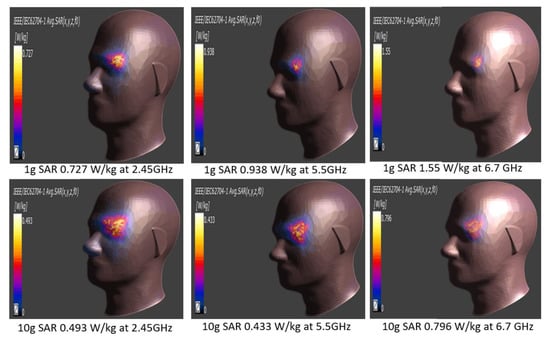
Figure 7.
SAR simulation results of antenna 1 at 2.4 GHz, 5.5 GHz, and 6.7 GHz.
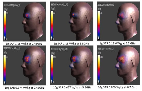
Figure 8.
SAR simulation results of antenna 3 at 2.4 GHz, 5.5 GHz, and 6.7 GHz.
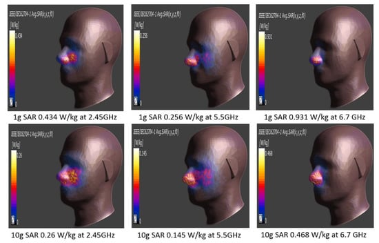
Figure 9.
SAR simulation results for antenna 5 at 2.4 GHz, 5.5 GHz, and 6.7 GHz.
In addition, the FCC regulations provide additional specifications. Therefore, when a wearable device supports frequencies above 6 GHz, additional test power density (PD) is required, and the PD specification must be less than 10 W/m2. Therefore, the authors performed PD simulations on three antennas at 6.7 GHz. Please refer to Figure 10, below, where it can be observed that when the input power is 0.1 W (20 dBm), the PD values of the three antennas at a frequency of 6.7 GHz are, respectively, 0.589 W/m2, 0.0443 W/m2, and 0.793 W/m2 for antennas 1, 3, and 5. Therefore, on the basis of the above results, it can be concluded that the PD values of the three antennas are all lower than the limit of 10 W/m2 specified in the FCC regulations.
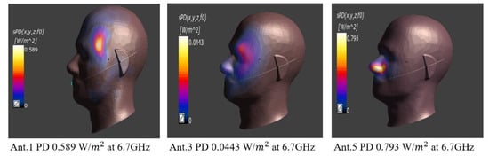
Figure 10.
The 6.7 GHz PD simulation results for antennas 1, 3 and 5.
4. Measurement Results
In this paper, the antenna is engraved on an FR4 substrate and assembled into the shape of VR glasses, as shown in Figure 11a, as a 6 × 6 MIMO glasses antenna. Figure 11b shows a single antenna, and it can be observed that it is very compact.
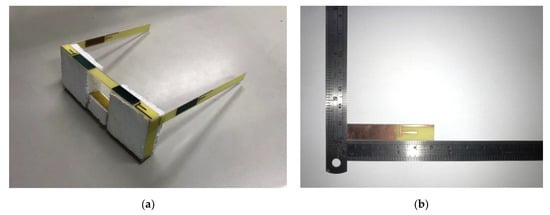
Figure 11.
(a) Photo of the glasses antenna; (b) single antenna.
4.1. S-Parameter Results
The S-parameters were measured using an Agilent E5071C network analyzer. Figure 12 presents a photograph of the measurement setup. Figure 13a shows the S-parameter measurement and simulation of antenna 1, antenna 3, and antenna 5 in free space. The results for antenna 1 are very close to the simulation results in the high-frequency part. The reflection coefficients of antenna 3 and antenna 5 are shifted to a lower frequency due to welding errors, but the overall bandwidth covers the Wi-Fi 6E frequency band. Figure 13b presents a comparison of the isolation of the three antennas in free space obtained by measurement and simulation. The results show that isolation of lower than −10 dB can be achieved.
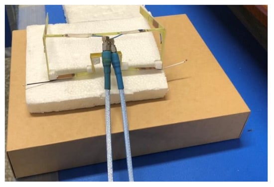
Figure 12.
The measurement setup with proposed antenna in free space.
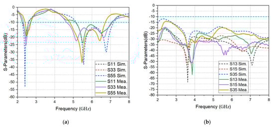
Figure 13.
The measurement and simulation results in free space. (a) Reflection coefficients of antennas 1, 3, and 5; (b) isolation between antennas 1, 3, and 5.
The glasses antenna was placed on a human head, as shown in Figure 14, for S-parameter measurement. Antenna 1 was closest to the head, so the reflection coefficient at 2.4 GHz shifted to a higher frequency, while antenna 3 and antenna 5 were very accurate in the 2.4 GHz frequency band. In Figure 15a, the antenna 1 result is very close to that of the simulation in the high-frequency block. The reflection coefficients measured by antenna 3 and antenna 5 are slightly shifted towards a lower frequency, but the overall bandwidth covers the Wi-Fi 6E frequency band. Figure 15b presents a comparison of the isolation values obtained via measurement and simulation for the three antennas. Isolation of lower than −10 dB can be achieved in the working range, and the isolation in the high-frequency band can even reach −20 dB.
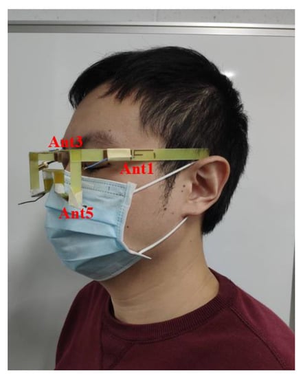
Figure 14.
The proposed antenna placed on a human head to measure S-parameters.
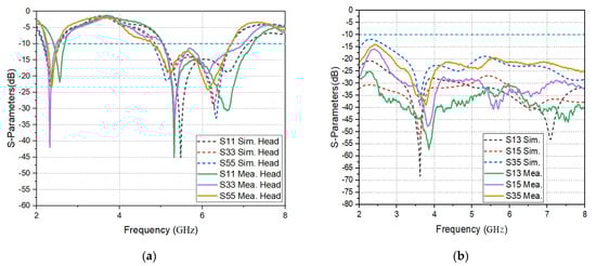
Figure 15.
Measured and simulated results of the proposed antenna on a human head: (a) reflection coefficients of antennas 1, 3, 5; (b) isolation between antennas 1, 3, 5.
4.2. Radiation Pattern
Next, the glasses implemented in this paper were placed in an anechoic chamber for far-field measurement, as shown in Figure 16. The measurement environment used was a standard far-field chamber, and the instrument used for measurement was an Anritsu MS46524B network analyzer. Measurement antenna in the far-field chamber was a horn antenna, with a measurement frequency range from 0.1 GHz to 8 GHz.
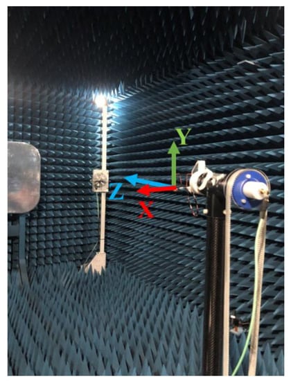
Figure 16.
The photograph of the far-field chamber and the axes.
Figure 17, Figure 18 and Figure 19 show the 2D gain pattern diagrams of the measured and simulated results of the three antennas in the three planes: the XY plane, the XZ plane, and the YZ plane, respectively. It can be seen that when the frequency points of the three antennas are 2.4 GHz, 5.5 GHz, and 6.7 GHz, the simulated and measured radiation modes exhibit the same trend.
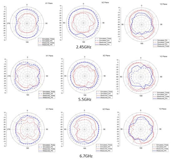
Figure 17.
2D radiation pattern simulation and measurement for antenna 1.
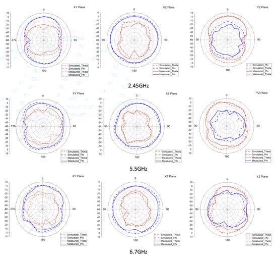
Figure 18.
2D radiation pattern simulation and measurement for antenna 3.
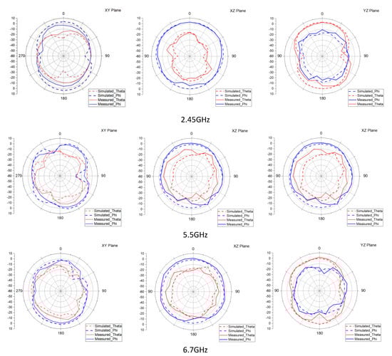
Figure 19.
2D radiation pattern simulation and measurement for antenna 5.
4.3. Efficiency, Gain, and ECC Results
Then, the antenna efficiency and gain were compared. From Figure 20a,b, it can be seen that the working band of antenna 1 can reach a peak gain of 1.8 dBi and an antenna efficiency of 84.41% in free space at 2.4 GHz. Meanwhile, at 5.5 GHz, peak gain reaches 4.7 dBi and an antenna efficiency of 86.55% is achieved. Finally, the peak gain at 6.7 GHz reaches 3.6 dBi and an antenna efficiency of 84.84% is achieved. From Figure 21a,b, it can be seen that the working frequency band of antenna 3 can reach a peak gain of 1.8 dBi and an antenna efficiency of 82.57% in free space at 2.4 GHz. Meanwhile, at 5.5 GHz, peak gain reaches 2.5 dBi and an antenna efficiency of 79.84% is achieved. Finally, the peak gain at 6.7 GHz reaches 3.6 dBi and an antenna efficiency of 84.84% is achieved. From Figure 22a,b, it can be seen that the working frequency band of antenna 5 can reach a peak gain of 1.8 dBi and an antenna efficiency of 75.41% in free space at 2.4 GHz. Meanwhile, at 5.5 GHz, peak gain reaches 3.7 dBi and antenna efficiency 86.55%. Finally, the peak gain at 6.7 GHz reaches 3.1 dBi and an antenna efficiency of 76.84% is achieved.
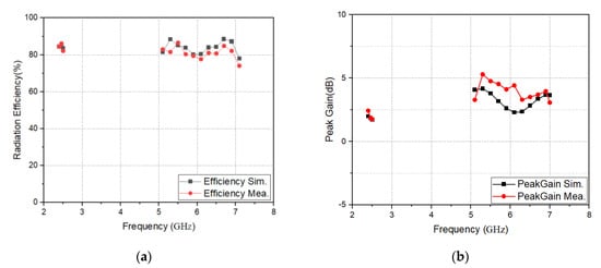
Figure 20.
(a) Simulated and measured efficiency of antenna 1; (b) simulated and measured gain of antenna 1.
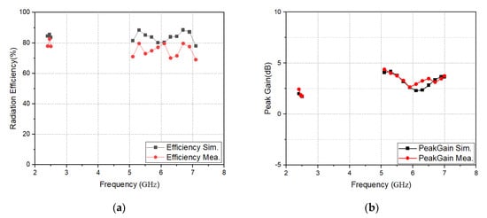
Figure 21.
(a) Simulated and measured efficiency of antenna 3; (b) simulated and measured gain of antenna 3.
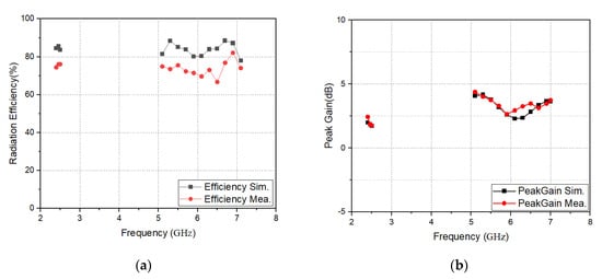
Figure 22.
(a) Simulated and measured efficiency of antenna 5; (b) simulated and measured gain of antenna 5.
The glasses antenna proposed in this article has a MIMO system. In addition to observing whether there is a mutual influence between the antennas through the isolation, the ECC value is usually used to judge whether the independence between the antennas is good. With the lower antenna coupling effect that ECC value will be lower and transmission efficiency will improve. The internationally recognized ECC limit value is 0.5. The authors used three states with larger ECC simulation values for measurement. The results show that the ECC values obtained are all lower than 0.05, as shown in Figure 23. The equation for calculating the ECC value is as follows [15]:
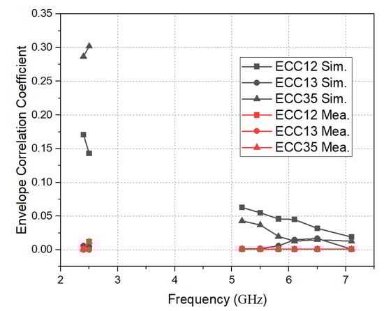
Figure 23.
ECC simulation and measured comparison of three antennas.
When antenna 1 is excited, it can be represented by ; when antenna 2 is excited, it can be represented by . Ω is the solid angle.
4.4. MIMO Performance
A MIMO antenna system was used to confirm whether the antenna design is useful by measuring the data throughput and the signal-to-noise ratio (SNR). The proposed glasses antenna was set up for measurement in an open conference room, and the distance between the transmitting antenna and the receiving antenna was 100 cm, as shown in Figure 24a. The test equipment was Measurement Systems Analysis (MSA). Due to the equipment limitations, only 2 × 2 MIMO function was possible, and the upper limit of the test frequency was 6 GHz; therefore, the authors sued two symmetrical antennas to measure 2.4 GHz and 5.5 GHz, with the first group consisting of antenna 1 and antenna 2, the second group consisting of antenna 3 and antenna 4, and the third group consisting of antenna 5 and antenna 6. The MSA measurement monitor is shown in Figure 24b.
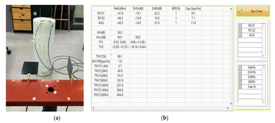
Figure 24.
(a) 2 × 2 MIMO test environment photograph; (b) MSA measurement monitor with throughput and SNR.
Table 2 shows the measurement results of the proposed glasses antenna in the 2 × 2 MIMO test. Based on three groups of 2 × 2 measurement data, it is possible to indirectly determine whether a 6 × 6 MIMO system is useful or not. Because the proposed antenna is a passive component, the function of MU-MIMO will also be excellent when the three groups of antennas operate well and they are sufficiently isolated. In wireless communication, larger SNR values suggest better antenna receiving performance. The SNR value of the combinations tested in this paper are all better than 15 dB, and the SNR value of the second group at 5.5 GHz test is better than 20 dB. In the throughput test, when the power was 10 dB, the three groups of tests were all better than 80%
Table 2.
The proposed glasses antenna 2 × 2 MIMO measurement results.
Table 3 shows a comparison between the antenna proposed in this paper and other reference with glasses antennas. It can be seen from Table 3 that the references that have Wi-Fi applications only work on a single band. For example, the glasses presented in Refs. [1,23,24] only cover Wi-Fi 2.4G, and the antenna efficiency is lower than 50%. The best efficiency achieved between these three references is only 46.8% [23]. Compared with Ref. [14], in this article, the 2.4 GHz operating band is increased. The advantage of the 2.4 GHz band is that it allows wireless products to still have a flexible choice of low power and low bandwidth. Some studies on glasses antennas also include LTE bands. The glasses antennas described in Refs. [2,3] support multiple LTE bands, but the antenna gain is not good. The antenna described in Ref. [25] supports IoT 5.8 GHz using a frame antenna, and the antennas described in Refs. [26,27] apply the frequency band to 60 GHz, although the proposed antennas in these three references do not have MIMO functions. None of the above references include complete antenna designs for Wi-Fi 6E frequency bands of 2.4 GHz, 5 GHz, and 6 GHz. It can be seen from Table 2 that the antenna proposed by the authors can be wholly applied on Wi-Fi 6E bands. The proposed antenna has good antenna gain, antenna efficiency, and a MIMO system.
Table 3.
Comparison of the proposed antenna with other reference glasses.
5. Conclusions
After the release of the IEEE 802.11 ax protocol in 2020, current Wi-Fi 6E wireless routers can support up to 8 × 8 MU-MIMO, which have eight antennas providing input or output at the same time, and adds multi-user capability to MIMO in the wireless realm. Modern IC designs and circuit layouts are compact. Therefore, the proposed 6 × 6 MIMO glasses antenna not only improves the basic transmission speed, but also uses six identical planar monopole antennas placed on the FR4, which is thinner than commercially available glasses. This design is able to perfectly combine the communication circuit and the glasses antenna, in order to maximize the utilization of the space of the smart glasses.
The proposed glasses antenna is similar to commercially available glasses, so the authors simulated SAR and PD. The simulation results show that the impact of the electromagnetic radiation from the glasses antenna on the human head is lower than the limits stipulated in the safety regulations of various countries. In addition, according to the measured 2D field pattern, the proposed antenna has a good gain and a perfect receiving range, and is almost able to support the operating frequency bands of Wi-Fi 6E and Wi-Fi 7. Based on the mentioned advantages, we have confidence that the proposed antenna will lead to great improvements in smart glasses products, making a large contribution to the design of smart glasses.
Author Contributions
Conceptualization, M.-A.C.; methodology, M.-A.C.; software, M.-A.C. and C.-W.H.; validation, C.-W.H.; formal analysis, M.-A.C. and C.-W.H.; investigation, M.-A.C.; resources, M.-A.C.; writing—original draft preparation, M.-A.C. and C.-W.H.; writing—review and editing, M.-A.C.; visualization, M.-A.C.; supervision, M.-A.C.; project administration, M.-A.C.; funding acquisition, M.-A.C. All authors have read and agreed to the published version of the manuscript.
Funding
This research received no external funding.
Conflicts of Interest
The authors declare no conflict of interest.
References
- Cihangir, A.; Gianesello, F.; Luxey, C. Dual antenna concept with complementary radiation for eyewear applications. IEEE Trans. Antennas Propag. 2018, 66, 3056–3063. [Google Scholar] [CrossRef]
- Wang, Y.Y.; Ban, Y.L.; Liu, Y. Sub-6GHz 4G/5G conformal glasses antennas. IEEE Access 2019, 7, 182027–182036. [Google Scholar] [CrossRef]
- Cihangir, A.; Panagamuwa, C.J.; Whittow, W.G.; Jacquemod, G.; Gianesello, F.; Pilard, R.; Luxey, C. Dual-band 4G eyewear antenna and sar implications. IEEE Trans. Antennas Propag. 2017, 65, 2085–2089. [Google Scholar] [CrossRef] [Green Version]
- Hu, X.; Yan, S.; Zhang, J.; Volskiy, V.; Vandenbosch, G.A.E. Omni-directional circularly polarized button antenna for 5 GHz WBAN applications. IEEE Trans. Antennas Propag. 2021, 69, 5054–5059. [Google Scholar] [CrossRef]
- Le, T.T.; Yun, T.Y. Miniaturization of a dual-band wearable antenna for WBAN applications. IEEE Antennas Wireless Propag. Lett. 2020, 19, 1452–1456. [Google Scholar] [CrossRef]
- Shahzad, M.A.; Paracha, M.N.; Naseer, S.; Ahmad, S.; Malik, M.; Farhan, M.; Ghaffar, A.; Hussien, M.; Sharif, A.B. An artificial magnetic conductor-backed CompactWearable antenna for smart watch IoT applications. Electronics 2021, 10, 2908. [Google Scholar] [CrossRef]
- Zhong, Y.; Wen, H.; Wang, K.; Lu, X.; Liang, Q.; Jiang, Z. A dual-band monopole antenna for WLAN in application. In Proceedings of the 2017 International Applied Computational Electromagnetics Society Symposium (ACES), Suzhou, China, 1–4 August 2017. [Google Scholar]
- Chen, A.; Sun, M.; Zhang, Z.; Fu, X. Planar monopole antenna with a parasitic shorted strip for multistandard handheld terminals. IEEE Access 2020, 8, 51648–51652. [Google Scholar] [CrossRef]
- Thiruvenkadam, S.; Parthasarathy, E.; Palaniswamy, S.K.; Kumar, S.; Wang, L. Design and performance analysis of a compact planar MIMO antenna for IoT applications. Sensors 2021, 21, 7909. [Google Scholar] [CrossRef]
- Smida, A.; Iqbal, A.; Alazemi, A.J.; Waly, M.I.; Ghayoula, R.; Kim, S. Wideband wearable antenna for biomedical telemetry applications. IEEE Access 2020, 8, 15687–15694. [Google Scholar] [CrossRef]
- Ghouz, H.H.M.; Sree, M.F.A.S.; Ibrahim, M.A. Novel wideband microstrip monopole AntennaDesigns for Wi-Fi/LTE/WiMax devices. IEEE Access 2020, 8, 9532–9539. [Google Scholar] [CrossRef]
- Mathur, P.; Augustine, R.; Gopikrshna, M.; Raman, S. Dual MIMO antenna system for 5G mobile phones, 5.2 GHz WLAN, 5.5 GHz WiMAX and 5.8/6 GHz Wi-Fi applications. IEEE Access 2021, 9, 106734–106742. [Google Scholar] [CrossRef]
- Cihangir, A.; Panagamuwa, C.J.; Whittow, W.G.; Gianesello, F.; Luxey, C. Ultrabroadband antenna with robustness to body detuning for 4G eyewear devices. IEEE Antennas Wirel. Propag. Lett. 2016, 8, 1225–1228. [Google Scholar] [CrossRef]
- Chung, M.A.; Hsiao, W.C.; Yang, C.W.; Chuang, B.R. 4 × 4 MIMO antenna system for smart eyewear in Wi-Fi 5G and Wi-Fi 6E wireless communication applications. Electronics 2021, 10, 2936. [Google Scholar] [CrossRef]
- Ali, H.; Ren, X.C.; Bari, I.; Bashir, M.A.; Hashmi, A.M.; Tareen, M.A.K.; Anjum, M.R. Four-Port MIMO antenna system for 5G n79 band RF devices. Electronics 2022, 11, 35. [Google Scholar] [CrossRef]
- Cai, C.A.; Kai, K.Y.; Liao, W.J. A WLAN/WiFi-6E MIMO antenna design for handset devices. In Proceedings of the 2021 International Symposium on Antennas and Propagation, Taipei, Taiwan, 19–22 October 2021. [Google Scholar]
- Wnag, W.; Zhang, M.; Bai, Z.; Guo, H.; Tan, E.K. Wi-Fi 6E test challenges on ATE. In Proceedings of the 2021 China Semiconductor Technology International Conference (CSTIC), Shanghai, China, 14–15 March 2021. [Google Scholar]
- Cihangir, A.; Whittow, W.; Panagamuwa, C.; Jacquemod, G.; Gianesello, F.; Luxey, C. 4G antennas for wireless eyewear devices and related SAR. Comptes Rendus Phys. 2015, 16, 836–850. [Google Scholar] [CrossRef] [Green Version]
- Matthaiou, M.; Koulouridis, S.; Kotsopoulos, S. A novel dual-band implantable antenna for pancreas telemetry sensor applications. Telecom 2022, 3, 1–16. [Google Scholar] [CrossRef]
- RF Exposure Procedures and Equipment Authorization Policies for Mobile and Portable Devices. 2015. Available online: https://apps.fcc.gov/oetcf/kdb/forms/FTSSearchResultPage.cfm?switch=P&id=20676 (accessed on 23 October 2015).
- IEEE Recommended Practice for Determining the Peak Spatial-Average Specific Absorption Rate (SAR) in the Human Head from Wireless Communications Devices: Measurement Techniques. Available online: https://ieeexplore.ieee.org/document/6589093 (accessed on 6 September 2013).
- FCC Wi-Fi 6E RF Exposure—FCC Report. 2021. Available online: https://fcc.report/FCC-ID/MSQI005D/5126834.pdf (accessed on 4 February 2021).
- Hong, S.; Kang, S.H.; Kim, Y.; Jung, C.W. Transparent and flexible antenna for wearable glasses applications. IEEE Trans. Antennas Propag. 2016, 64, 2797–2804. [Google Scholar] [CrossRef]
- Choi, S.; Choi, J. Miniaturized MIMO antenna with a high isolation for smart glasses. In Proceedings of the IEEE-APS Topical Conference on Antennas and Propagation in Wireless Communications (APWC), Verona, Italy, 11–15 September 2017. [Google Scholar]
- Wang, Y.; Zhang, J.; Peng, F.; Wu, S. A glasses frame antenna for the applications in internet of things. IEEE Internet Things J. 2019, 6, 8911–8918. [Google Scholar] [CrossRef]
- Bisognin, A.; Cihangir, A.; Luxey, C.; Jacquemod, G.; Pilard, R.; Gianesello, F.; Costa, J.R.; Fernandes, C.A.; Lima, E.B.; Panagamuwa, C.J.; et al. Ball grid array-module with integrated shaped lens for WiGig applications in eyewear devices. IEEE Trans. Antennas Propag. 2017, 65, 6380–6394. [Google Scholar] [CrossRef]
- Hong, Y.; Chou, J. 60 GHz patch antenna array with parasitic elements for smart glasses. IEEE Antennas Wirel. Propag. Lett. 2018, 17, 1252–1256. [Google Scholar] [CrossRef]
Publisher’s Note: MDPI stays neutral with regard to jurisdictional claims in published maps and institutional affiliations. |
© 2022 by the authors. Licensee MDPI, Basel, Switzerland. This article is an open access article distributed under the terms and conditions of the Creative Commons Attribution (CC BY) license (https://creativecommons.org/licenses/by/4.0/).