Article

Design and Implementation of a Miniaturized Filtering Antenna for 5G Mid-Band Applications

by
Fatimah K. Juma’a
1,
Alaa I. Al-Mayoof
2,
Abdulghafor A. Abdulhameed
3,4,
Falih M. Alnahwi
1,
Yasir I. A. Al-Yasir
5,* and
Raed A. Abd-Alhameed
5,6
1
Department of Electrical Engineering, College of Engineering, University of Basrah, Basrah 61001, Iraq
2
Communication Engineering Department, Iraq University College, Basrah 61001, Iraq
3
Department of Electronics and Information Technology, Faculty of Electrical Engineering, University of West Bohemia, 301 00 Pilsen, Czech Republic
4
Department of Electrical Techniques, Qurna Technique Institute, Southern Technical University, Basra 61001, Iraq
5
Faculty of Engineering and Informatics, University of Bradford, Bradford BD7 1DP, UK
6
Department of Information and Communication Engineering, Basrah University College of Science and technology, Basrah 61004, Iraq
*
Author to whom correspondence should be addressed.
Electronics 2022, 11(19), 2979; https://doi.org/10.3390/electronics11192979
Submission received: 24 August 2022 / Revised: 12 September 2022 / Accepted: 19 September 2022 / Published: 20 September 2022
(This article belongs to the Special Issue RF/Microwave Circuits for 5G and Beyond)

Abstract

:
Combining a microwave filter with an antenna results in a low-cost, efficient, and small-size selective radiator called a filtering antenna or filtenna. In this work, a compact filtering antenna is presented to radiate within the 5G mid-band frequencies along (3.6–3.8 GHz) with strong rejection for the frequencies outside this range. The proposed filtering antenna consists of a crescent-shaped planar monopole antenna that is electromagnetically coupled with a reduced-size capacitively loaded loop (CLL) microwave band-pass filter. The miniaturization of CLL is achieved by utilizing a single ring CLL structure instead of two rings to reduce the filter size to half without affecting the filter performance. The filtering antenna in this work is fabricated on a Rogers RT5880 substrate with dimensions equal to 24.2 × 27 × 0.8 mm3. Good congruence between the measurements and the simulation results, and both verify the antenna’s perfect operation along the 5G mid-band frequency range. The simulated and measured peak realized gain values of the proposed structure are 2.24 dB and 2.2 dB, respectively. Furthermore, the power pattern of the designed filtering antenna is omnidirectional, which is very convenient for portable 5G mid-band devices. Compared to other works, it is found that in spite of the small dimensions of the filtering antenna (24.2 × 27 × 0.8 mm3), the antenna has a bandwidth that covers the range 3.6–3.82 GHz with a maximum gain value equal to 2.2 GHz and omnidirectional pattern which makes the antenna very suitable for 5G mid-band applications.

1. Introduction

With the emergence of wireless transmission and to attain a wide wireless connection of data, the antenna was invented as an element that provides an interface between the guided electrical signals and the electromagnetic waves [1]. However, most of the designed antennas have an effective out-of-band radiation, such as the antennas utilized for cognitive radio applications [2,3], Radio Frequency Identification (RFID) applications [4,5], Wireless Local Area Network (WLAN)/Worldwide Interoperability for Microwave Access (WiMAX) applications [6,7], C and X-band applications [8,9] and 5G applications [10,11]. Therefore, many microwave band-pass filters (BPFs) were proposed to suppress the unintended out-of-band radiation. BPF is a device that provides a suppression for signals whose frequencies are outside a certain frequency band. Many planar BPF have been proposed to be compatible with the planar printed circuit antennas such as stub- loaded multiple mode resonator [12,13], tapped feeds hairpin filter [14,15], dual-band stepped-impedance resonator (SIR) BPF with enhanced selectivity [16,17], and capacitively loaded loop (CLL) filter [18,19].
In response to this, researchers have directed their focus toward designing a single element that combines the antenna feature and the selective filter behavior, and this combination is called a filtering antenna or simply filtenna. In [20], the authors attached a Γ-shaped antenna to a compact filter with three poles for WLAN applications. A filtering antenna for cognitive radio was also presented to achieve selective radiation during the communication mode of the system [21,22]. Fourth and fifth order filters were terminated by the cavity-backed antenna to cancel the undesired back radiation [23]. The circularly polarized filtering antenna was also utilized for X-band satellite applications [24]. In [25], the filtering antenna was used as a wearable antenna for ethanol detection. It is worth mentioning that the filtering antennas can also be presented for wideband applications with band notches to avoid interference with some critical applications, such as the designs proposed in [26,27].
This work presents a miniaturized CLL filter terminated with a crescent-shaped planar monopole antenna to form a filtering antenna for 5G sub-6 GHz applications (3.6–3.8 GHz). The compactness in the filtering antenna size is mainly attained by using a single arm of the CLL filter, and then it is electromagnetically coupled with the antenna to obtain an antenna size equal to 24.2 × 27 × 0.8 mm3. Rogers RT5880 is used as a substrate of the proposed design. The simulation and measured results of this design show a perfect coverage for the intended frequency band with good gain value and an omnidirectional power pattern suitable for 5G mid-band portable gadgets. The rest of the paper is organized as follows. Section 2 is a literature review of some related works. The dimensions and the overall structure of the proposed filtering antenna are presented in Section 3, while Section 4 studies the steps that were followed for combining the CLL filter with the crescent-shaped antenna. The effect of some important parameters on the performance of the antenna is demonstrated in Section 5, whereas Section 6 includes the measured results of the fabricated version of the proposed filtering antenna. Finally, the paper is summarized by a brief conclusion in Section 7.

2. Related Works

Many researchers have preferred the design of a filtering antenna to provide a radiating element with filtering capability in one element. Different designs have been proposed to meet the requirements of the filtering antenna structure. A Γ-shaped antenna was attached to a three poles compact filter to serve the WLAN application [20]. Filtering antennas were also exploited for cognitive radio applications to achieve a selective communication mode as well as a selective sensing mode of operation [21,22]. A filtering antenna with fourth and fifth-order filters and cavity-backed antenna for back radiation reduction purposes was proposed in [23]. The circularly polarized filtering antenna in [24] was designed for X-band military satellite applications. In [25], a wearable filtering antenna was used as an Ethanol detection sensor. In addition, the filtering antennas were also used in the front end of the wideband applications with band notches to eliminate the interference with some critical applications that intervene in the desired application operational band [26,27]. An end-fire filtering antenna was presented in [28] with a complex stacked structure to emulate the operation of Yagi-Uda antenna. A large size filtering antenna was introduced in [29] with defected ground plane and a slotted rectangular patch to operate for WLAN applications with high performance. In [30], a defected ground plane was utilized as a filter for 4 × 1 array of annular-shaped antenna to provide selective communication for Ku-band applications. A dual-band filtering antenna structure was designed in [31] using a dual-band planar band-pass filter with a conventional rectangular planar monopole antenna to limit its operation within the WiMAX and WLAN applications. In [32], a stacked structure with a complex substrate integrated waveguide (SIW) was utilized for 5G sub-6 GHz applications.
All the aforementioned works either tolerate the dimensions of the filtering antenna to get reasonable antenna gain or tolerate the antenna gain for the sake of the antenna size reduction. Therefore, it is important to make a balance between the gain value of the filtering antenna and the reduction in the filtering antenna size. This work is focused on filtering antenna has a relatively reduced size with reasonable gain value along the 5G mid-band range of frequencies, as will be explained in the next sections.

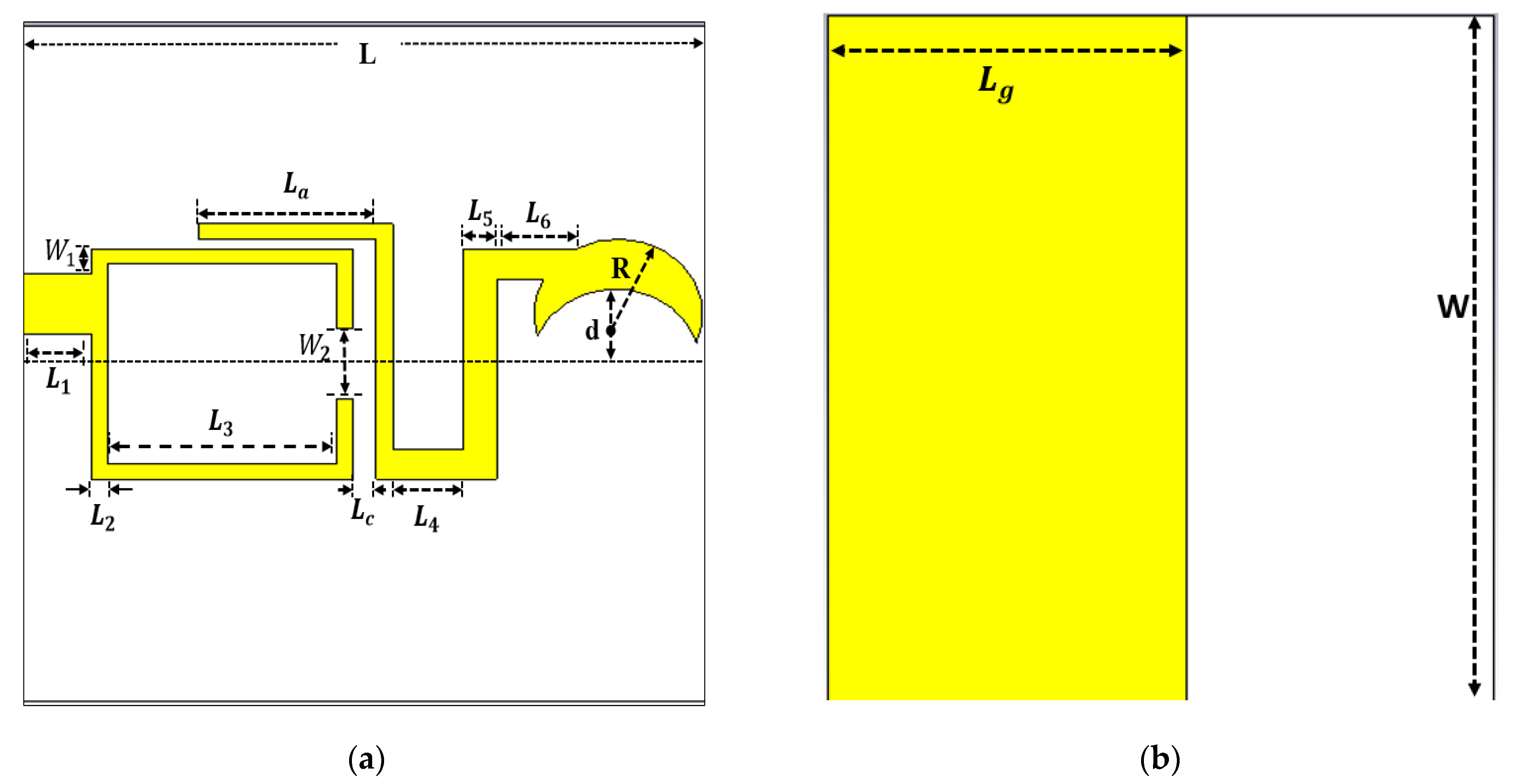
3. Antenna Structure

The proposed monopole crescent-shaped antenna and the single ring CLL band-pass filter are combined together as a single module and fed by a 50 Ω microstrip line. Figure 1 reveals the dimensions of each part of the proposed filtering antenna. The substrate proposed module is Rogers RT5880 with a relative permittivity of ε r = 2.2 . The loss tangent of the substrate is equal to δ = 0.0009 , while its height is equal to h = 0.8   mm . The overall size of the filtering antenna is 24.2 × 27 × 0.8 mm3. The best values of the parameters of the filtering antenna are given in Table 1.

4. Design Steps

As mentioned earlier, the design in this work consists of a compact CLL-based filter that is electromagnetically coupled with a planar monopole antenna. Consequently, the design steps can be concluded by demonstrating the design of the compact CLL filter and then studying its effect after attaching it to the monopole antenna. It is important to mention that the simulation results are obtained using CST Microwave Studio suite [33].

4.1. Design of CLL-Based Filter

The band-pass filter used in this work is a combination of two square-shaped capacitively loaded loop (CLL) [19]. Figure 2 shows that each CLL arm is a half wavelength resonator. A 50 Ω microstrip feed line is used to feed each arm of the CLL-based filter. The center frequency of this filter is intended to be at 3.7 GHz, and its bandwidth is intended to cover the 5G sub-6 GHz range (3.6–3.8 GHz). The dimensions of the filter are 27 × 24.2 × 0.8 mm3, and the total length of each CLL-element is around 35.7 mm based on Equation (1) given below [1]:
l = λ g 2 = c 2 f r ε r e f f
where λ g represents the guided wavelength, f r represents the resonant frequency, c denotes the speed of light in free space. ε r e f f denotes the effective relative permittivity, which can be related to the relative permittivity ε r by Equation (2) below [1]:
ε r e f f = ε r + 1 2 + ε r 1 2   1 + 12 h W p 1 / 2
where W p represents the width of the microstrip line, and h denotes the height of the dielectric substrate.
CLL filter has two different resonant frequencies. To give a reasonable interpretation for the generation of the two resonant frequencies, the equivalent circuit of the CLL filter is analyzed at the plane of symmetry (T-T’) as shown in Figure 3, which represents the equivalent circuit of the filter based on its T and π equivalent networks explained in [34]. The circuit has a low resonant frequency as [35]:
f o = 1 / 2 π [ L C + C m 1 2
where T-T’ is a short circuit to form the odd mode. Besides, the higher resonant frequency of the circuit is given by [35]:
f e = 1 / 2 π [ L C C m 1 2
where the plane of symmetry plane T-T’ is in the even mode (open circuit).
Figure 4 illustrates the current distribution of the CLL-based filter to verify both of its operation modes. At the lower (odd) resonant frequency (3.65 GHz), the current of each ring is in phase with that of the other arm. Therefore, the current is maximum at the boundary T-T’ with zero voltage, equivalent to a short circuit case (see Figure 4a). In adverse, the even mode appears at the frequency of 3.76 GHz, as illustrated in Figure 4b, where the current of each ring flows in the opposite direction with respect to that of the other ring. As a result, current cancellation occurs at T-T’, which is equivalent to an open circuit.
The S-parameters of the CLL-based filter are illustrated in Figure 5. The reflection coefficient ( S 11 ) reveals two overlapped resonant modes for the antenna where the resonant frequency for each mode is 3.65 GHz and 3.76 GHz. The filter bandwidth is 220 MHz which occupies the range of (3.6–3.82 GHz). Besides, the transmission coefficient ( S 21 ) of the filter exhibits a flat response at the pass band of the filter. In addition, the insertion loss of this filter is less than 1 dB along the pass band with two deep transmission zeros (3.25 GHz and 4.4 GHz) in the stop bands.

4.2. Design of Filtering Antenna

It can be noticed that the dimensions of the above filter are relatively large, so the resulting filtering antenna that is obtained from this filter would certainly be large. Therefore, it is essential to make some modifications to miniaturize the filter size before attaching it to an antenna. As discussed in the previous subsection, the CLL-based filter holds two arms that are electromagnetically coupled to each other [19]. One of the rings is canceled in this work for size reduction purposes. The idea of reducing the filter size to half by getting rid of one arm of the CLL has come up with by the fact that “the two half-wavelength arms of the CLL-based filter are presented to ensure the symmetry of the filter in terms of the forward (S21) and reverse (S12) transmission coefficients”. It is known that the filtering antenna has only a single port, so one arm of the CLL is enough to perform the filtering function of the proposed design. As a result, the crescent-shaped monopole antenna shown below in Figure 6 is attached to a single ring of the CLL-based filter to form the filtering antenna shown previously in Figure 1.
For comparison purposes, Figure 7a shows the simulation reflection coefficient of the antenna without a filter and the proposed (antenna + filter) model. It is clear that the monopole antenna has a large out-of-band matching which causes significant interference with adjacent applications. However, the filtering antenna results in a sharp reflection coefficient of almost stable value along the operational bandwidth, and strong suppression for the out-of-band signals. The resulting filtering antenna bandwidth is equal to 220 MHz extending from 3.6 GHz to 3.82 GHz, which is very close to the 5G mid-band application (3.6–3.8 GHz). To verify the energy transmission between the filter and the antenna, Figure 7b exhibits the current distribution at 3.7 GHz. It is clear that the current flows from the filter to the antenna to be radiated through it.

5. Parametric Study

The simulated reflection coefficient of the filtering antenna for different values of L a is depicted in Figure 8. Changing L a greatly modifies the impedance bandwidth of the present design because it operates as a tuning stub to manipulate the filter-antenna coupling, which results in controlling the locations of the two resonant frequencies. L a = 5.09 mm represents the suitable length that results in impedance matching for 5G mid-band frequency range.
As illustrated in Figure 9, the matching between the feed line and the filtering antenna is strongly affected by tuning the distance between the filter and the antenna L c . This is because the separation between the CLL band-pass filter and the antenna determines the strength of the coupling of the filtering antenna. It can easily be found that L c = 0.7 mm results in impedance bandwidth extended over the band (3.6–3.82 GHz), which perfectly occupies the 5G mid-band applications.
The reflection coefficient of the filtering antenna after varying   L g , which represents the length of the ground plane is shown in Figure 10. It is obvious that   L g has a subtle effect on the first resonant frequency, but the second resonant frequency is effectively influenced by the ground plane length. L g = 13 mm is very convenient to make the design cover the desired bandwidth of the 5G mid-band applications.

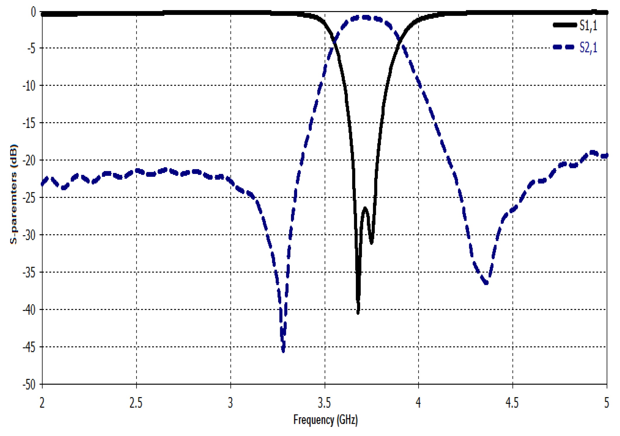
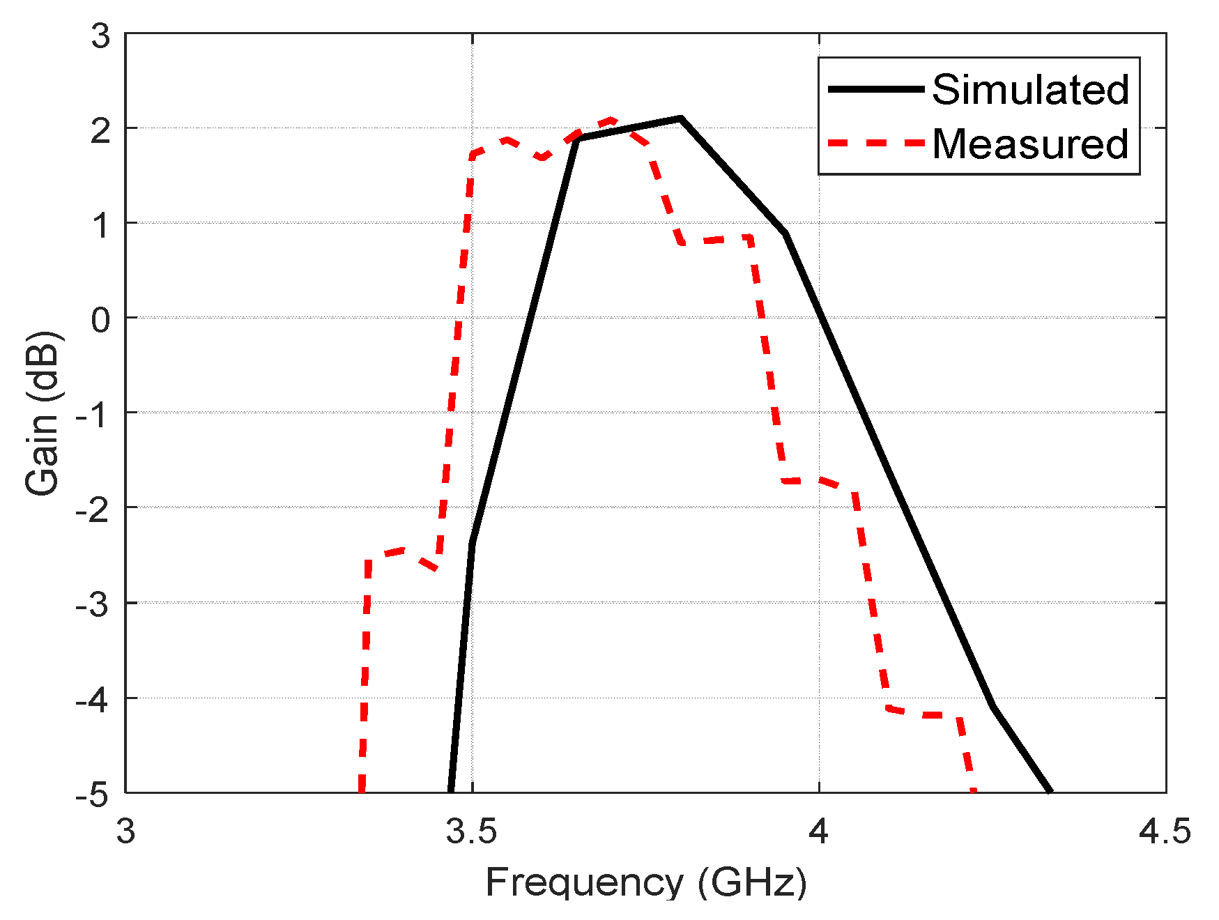
6. Measurement Results

The front and the back views of the fabricated version of the designed filtering antenna are exhibited in Figure 11, while the reflection coefficient measurement and radiation pattern measurement setups are demonstrated in Figure 12a,b, respectively. The measurements were acquired using Amitec VNA40 network analyzer. As mentioned in Section 2, the overall dimensions of the filtering antenna are 24.2 × 27 × 0.8 mm3, and it is fabricated on Rogers RT5880 dielectric substrates with a relative permittivity of ε r = 2.2 , a thickness 0.8 mm, and a loss tangent equal to 0.0009.
The reflection coefficient (simulated and measured) of the proposed design is illustrated in Figure 13. The simulated bandwidth of the proposed filtering antenna is 220 MHz extended over the band (3.6–3.82 GHz), whereas the bandwidth of the measured reflection coefficient is equal to 240 MHz covering the range (3.56–3.8 GHz). The difference between the simulation and measurements may be referred to the imperfection of the engraving machine, the SMA connector imperfect soldering, and the irregular variation of the value of the relative permittivity with the frequency.
Figure 14 shows the simulated and measured gains as a function of frequency. The simulated peak value of the gain is equal to 2.24 dB, whereas the measured peak value is equal to 2.2 dB. The simulated and measured normalized power patterns at 3.7 GHz in the E- and H-planes are illustrated in Figure 15. It is clear that the power pattern is omnidirectional and very suitable for portable 5G devices. The fluctuations in the measured power pattern and the gain results from the signals reflecting back from the surrounding objects in the anechoic chamber of the laboratory.
As a matter of comparison, the performance of the filtering antenna in this work compared with other important designs is listed below in Table 2. It is found that the proposed design makes a good balance between the antenna size, bandwidth, and realized gain. It is important to recall that the antenna gain value should exceed 0 dBi along the antenna frequency band [1], so the miniaturization process should not result in a gain value below the mentioned margin. This criterion has been met in this work because the size reduction of the proposed filtering antenna does not reduce the gain value below the threshold along the operational band of the antenna (see Figure 14). In addition, the reduction in the gain value also comes from the omnidirectional pattern of the antenna, which has lower gain than the directional antennas [1].
It is important to mention that the proposed filtering antenna covers the frequency range of LTE band 43 (3.6–3.8 GHz). Therefore, it is not suitable for systems that operate for LTE bands 42 and 43, which require additional coverage for band 42 (3.4–3.6 GHz).

7. Conclusions

A compact 5G mid-band filtering antenna that is composed by combining a crescent-shaped antenna and a single arm CLL band-pass filter has been designed in this paper. The miniaturization of the design mainly resides in reducing the filter size by 50% in addition to the compact size of the crescent-shaped antenna. In spite of its compact dimensions (24.2 × 27 × 0.8 mm3), the proposed filtering antenna perfectly covers the 5G mid-band frequency range of 3.6–3.8 GHz with acceptable realized gain along the band with strong elimination for the frequencies outside the desired band. The measured maximum gain is found to be equal to 2.2 dB with an omnidirectional power pattern that is convenient for portable 5G sub-6 GHz gadgets. For future work, a MIMO version of the proposed filtering antenna will be designed to be more compatible with 5G mid-band portable gadgets.

Author Contributions

Conceptualization, F.K.J., F.M.A. and Y.I.A.A.-Y.; methodology, F.K.J. and F.M.A.; investigation, F.M.A., A.A.A., Y.I.A.A.-Y., A.I.A.-M., A.A.A. and R.A.A.-A.; resources, F.M.A., Y.I.A.A.-Y., A.I.A.-M. and R.A.A.-A.; writing—original draft preparation, F.K.J., F.M.A., Y.I.A.A.-Y. and A.A.A.; writing—review and editing, F.M.A., Y.I.A.A.-Y., F.K.J., A.A.A. and R.A.A.-A.; visualization, F.M.A., Y.I.A.A.-Y. and A.A.A. All authors have read and agreed to the published version of the manuscript.

Funding

This research received no external funding.

Conflicts of Interest

The authors declare no conflict of interest.

References

  1. Balanis, C.A. Antenna Theory: Analysis and Design; John Wiley and Sons: Hoboken, NJ, USA, 2016. [Google Scholar]
  2. Gayatri, T.; Anveshkumar, N.; Sharma, V.K. A Hexagon Slotted Circular Monopole UWB Antenna for Cognitive Radio Applications. In Proceedings of the 2020 International Conference on Emerging Trends in Information Technology and Engineering (ic-ETITE), Vellore, India, 24–25 February 2020; pp. 1–5. [Google Scholar]
  3. Kantemur, A.; Tak, J.; Siyari, P.; Abdelrahman, A.H.; Krunz, M.; Xin, H. A Novel Compact Reconfigurable Broadband Antenna for Cognitive Radio Applications. IEEE Trans. Antennas Propag. 2020, 68, 6538–6547. [Google Scholar] [CrossRef]
  4. Ali, S.H.; Reja, A.H.; Hachim, Y.A. Design a Compact Coplanar Wideband Antenna Used in Radio Frequency Identification Systems. Iraqi J. Electr. Electron. Eng. 2020. [Google Scholar] [CrossRef]
  5. Dong, Y.; Wang, Z.; Pan, Y.; Choi, J.H. Characterization of Shorted Dipole Antennas for Low-Cost RFID Reader Applications. IEEE Trans. Antennas Propag. 2020, 68, 7297–7308. [Google Scholar] [CrossRef]
  6. Madina, R.; Rahardjo, E.T.; Zulkifli, F.Y. Multiband Wideband Monopole Antena Using RSRR for WLAN and WiMAX Applications. In Proceedings of the 2019 IEEE R10 Humanitarian Technology Conference (R10-HTC) (47129), Depok, West Java, Indonesia, 12–14 November 2019; pp. 16–18. [Google Scholar]
  7. Mkindu, H.; Iddi, H. Multi-Bands Circular Ring Monopole Antenna with Double L-Shape for WLAN/WiMAX Applications. Tanzan. J. Sci. 2021, 47, 228–242. [Google Scholar]
  8. Alnahwi, F.M.; Al-Yasir, Y.I.A.; Ali, N.T.; Gharbia, I.; See, C.H.; Abd-Alhameed, R.A. A Compact Wideband Circularly Polarized Planar Monopole Antenna with Axial Ratio Bandwidth Entirely Encompassing the Antenna Bandwidth. IEEE Access 2022, 10, 81828–81835. [Google Scholar] [CrossRef]
  9. Djengomemgoto, G.; Altunok, R.; Karabacak, C.; Imeci, S.T.; Durak, T. Dual-band Gemini-shaped Microstrip Patch Antenna for C-band and X-band applications. In Proceedings of the 2017 International Applied Computational Electromagnetics Society Symposium—Italy (ACES), Firenze, Italy, 26–30 March 2017; pp. 1–2. [Google Scholar]
  10. Alnahwi, F.M.; Al-Yasir, Y.I.A.; See, C.H.; Abd-Alhameed, R.A. Single-Element and MIMO Circularly Polarized Microstrip Antennas with Negligible Back Radiation for 5G Mid-Band Handsets. Sensors 2022, 22, 3067. [Google Scholar] [CrossRef]
  11. Zeng, J.; Luk, K.-M. Single-Layered Broadband Magnetoelectric Dipole Antenna for New 5G Application. IEEE Antennas Wirel. Propag. Lett. 2019, 18, 911–915. [Google Scholar] [CrossRef]
  12. Alnahwi, F.M.; Al-Yasir, Y.I.A.; Abdulhameed, A.A.; Abdullah, A.S.; Abd-Alhameed, R.A. A Low-Cost Microwave Filter with Improved Passband and Stopband Characteristics Using Stub Loaded Multiple Mode Resonator for 5G Mid-Band Applications. Electronics 2021, 10, 450. [Google Scholar] [CrossRef]
  13. Al-Yasir, Y.; Tu, Y.; Ojaroudi Parchin, N.; Abdulkhaleq, A.; Alnahwi, F.; Abd-Alhameed, R. Dual-Wide Band Stub Loaded Step Impedance Resonator Filter with Folded Meander Couple Lines. In Proceedings of the 1st International Multi-Disciplinary Conference Theme: Sustainable Development and Smart Planning, IMDC-SDSP 2020, Cyperspace, 28–30 June 2020. [Google Scholar]
  14. Lin, S.-C.; Chiou, P.-Y.; Chen, Y.-M.; Chang, S.-F. An Accurate Filtenna Synthesis Approach Based on Load-Resistance Flattening and Impedance-Transforming Tapped-Feed Techniques. IEEE Access 2018, 6, 24568–24581. [Google Scholar] [CrossRef]
  15. Ono, S.; Wada, K. Design and Fabrication of 3-Pole BPF Configured by Hairpin Resonators and Different Types of Coupling and Feed Types at 20 GHz. In Proceedings of the 2018 Asia-Pacific Microwave Conference (APMC), Kyoto, Japan, 6–9 November 2018; pp. 1363–1365. [Google Scholar]
  16. Gomez-Garcia, R.; Yang, L.; Munoz-Ferreras, J.-M.; Psychogiou, D. Selectivity-Enhancement Technique for Stepped-Impedance-Resonator Dual-Passband Filters. IEEE Microw. Wirel. Compon. Lett. 2019, 29, 453–455. [Google Scholar] [CrossRef]
  17. Wen, P.; Ma, Z.; Liu, H.; Zhu, S.; Ohira, M.; Wang, C.; Guan, X.; Ren, B. Novel Compact Dual-Band BPF Using Stub-Loaded Shorted Stepped-Impedance Resonators. In Proceedings of the 2018 Asia-Pacific Microwave Conference (APMC), Kyoto, Japan, 6–9 November 2018; pp. 22–24. [Google Scholar]
  18. Dakhli, S.; Smari, M.; Choubani, F.; Floch, J.-M. Microstrip Stop-band RF Filter at Microwave Frequencies Using CLLs Elements. In Proceedings of the 2020 4th International Conference on Advanced Systems and Emergent Technologies (IC_ASET), Hammamet, Tunisia, 15–18 December 2020; pp. 306–309. [Google Scholar]
  19. Tang, M.-C.; Chen, Y.; Ziolkowski, R.W. Experimentally Validated, Planar, Wideband, Electrically Small, Monopole Filtennas Based on Capacitively Loaded Loop Resonators. IEEE Trans. Antennas Propag. 2016, 64, 3353–3360. [Google Scholar] [CrossRef] [Green Version]
  20. Wei-Jun, W.; Ying-Zeng, Y.; Shao-Li, Z.; Zhi-Ya, Z.; Jiao-Jiao, X. A New Compact Filter-Antenna for Modern Wireless Communication Systems. IEEE Antennas Wirel. Propag. Lett. 2011, 10, 1131–1134. [Google Scholar] [CrossRef]
  21. Hasan, Y.M.; Abdullah, A.S.; Alnahwi, F.M. Dual-Port Filtenna System for Interweave Cognitive Radio Applications. Iran. J. Sci. Technol. Trans. Electr. Eng. 2022. [Google Scholar] [CrossRef]
  22. Atallah, H.A.; Abdel-Rahman, A.B.; Yoshitomi, K.; Pokharel, R.K. Compact frequency reconfigurable filtennas using varactor loaded T-shaped and H-shaped resonators for cognitive radio applications. IET Microw. Antennas Propag. 2016, 10, 991–1001. [Google Scholar] [CrossRef]
  23. Yun, J.; Trinh-Van, S.; Park, J.-Y.; Yang, Y.; Lee, K.-Y.; Hwang, K.C. Cavity-Backed Patch Filtenna for Harmonic Suppression. IEEE Access 2020, 8, 221580–221589. [Google Scholar] [CrossRef]
  24. Wang, W.; Jin, H.; Yu, W.; Zhang, X.H.; Wu, F.; Chin, K.-S.; Luo, G.Q. A Single-Layer Dual-Circularly Polarized SIW-Cavity-Backed Patch Filtenna with Wide Axial-Ratio Bandwidth. IEEE Antennas Wirel. Propag. Lett. 2021, 20, 908–912. [Google Scholar] [CrossRef]
  25. Benassi, F.; Paolini, G.; Masotti, D.; Costanzo, A. A Wearable Flexible Energy-Autonomous Filtenna for Ethanol Detection at 2.45 GHz. IEEE Trans. Microw. Theory Tech. 2021, 69, 4093–4106. [Google Scholar] [CrossRef]
  26. Mohamadzade, B.; Simorangkir, R.B.V.B.; Hashmi, R.M.; Chao-Oger, Y.; Zhadobov, M.; Sauleau, R. A Conformal Band-Notched Ultrawideband Antenna with Monopole-Like Radiation Characteristics. IEEE Antennas Wirel. Propag. Lett. 2020, 19, 203–207. [Google Scholar] [CrossRef]
  27. Hasan, Y.M.; Abdullah, A.S.; Alnahwi, F.M. UWB Filtenna with Reconfigurable and Sharp Dual-Band Notches for Underlay Cognitive Radio Applications. Prog. Electromagn. Res. C 2022, 120, 45–60. [Google Scholar] [CrossRef]
  28. Chen, C. A Compact Wideband Endfire Filtering Antenna Inspired by a Uniplanar Microstrip Antenna. IEEE Antennas Wirel. Propag. Lett. 2022, 21, 853–857. [Google Scholar] [CrossRef]
  29. El Ouadi, Z.; Amadid, J.; Khabba, A.; El Yassini, A.; Ibnyaich, S.; Zeroual, A. Compact Microstrip Filtenna Designed for Wireless Local Area Network Applications. In Proceedings of the 2022 International Conference on Decision Aid Sciences and Applications (DASA), Chiangrai, Thailand, 23–25 March 2022; pp. 1593–1597. [Google Scholar]
  30. T, K.; Lalitha, S.K. Defected Ground Structure Implementation for Slotted Annular Ring Microstrip Filtenna. In Proceedings of the 2022 2nd International Conference on Intelligent Technologies (CONIT), Hubli, India, 24–26 June 2022; pp. 1–4. [Google Scholar]
  31. Turkeli, A.; Gorur, A.K.; Altuncu, Y. Design of a Novel Dual-Wideband Filtenna. In Proceedings of the 2022 Microwave Mediterranean Symposium (MMS), Pizzo Calabro, Italy, 9–13 May 2022; pp. 1–4. [Google Scholar]
  32. Meyer, E.; Vertegaal, C.; Johnson, L.; Meyer, P.; Johannsen, U. Substrate Integrated Waveguide Pedestal Filtenna for Sub-6 GHz 5G Radio Frequency Front-Ends. In Proceedings of the 2022 16th European Conference on Antennas and Propagation (EuCAP), Madrid, Spain, 27 March–1 April 2022; pp. 1–5. [Google Scholar]
  33. CST Studio Suite. CST Microwave Studio Suite; Dassault Systèmes UK: Coventry, UK, 2014. [Google Scholar]
  34. Pozar, D.M. Microwave Engineering; John Wiley & Sons: Hoboken, NJ, USA, 2011. [Google Scholar]
  35. Garg, R.; Bahl, I.; Bozzi, M. Microstrip Lines and Slotlines; Artech House: London, UK, 2013. [Google Scholar]
Figure 1. Structure of the proposed filtering antenna: (a) top view; (b) back view (the white color represents the dielectric and the yellow color is the conductor).
Electronics 11 02979 g001
Figure 2. Structure of the CLL-based BPF (all dimensions are in mm (the white color represents the dielectric and the yellow color is the conductor).
Electronics 11 02979 g002
Figure 3. The circuit diagram of CLL-based BPF.
Electronics 11 02979 g003
Figure 4. Current distribution of proposed CLL based BPF: (a) odd-mode; (b) even-mode.
Electronics 11 02979 g004
Figure 5. Simulated transmission and reflection coefficients of the CLL-based BPF.
Electronics 11 02979 g005
Figure 6. Structure of the crescent-shaped monopole antenna: (a) top view; (b) bottom view (the white color represents the dielectric and the yellow color is the conductor).
Electronics 11 02979 g006
Figure 7. (a) Reflection coefficient of the monopole antenna and the antenna after attaching it to a CLL-based BPF; (b) current distribution of the proposed filtering antenna at 3.7 GHz.
Electronics 11 02979 g007
Figure 8. The designed filtering antenna reflection coefficients with L g = 13 mm, L c = 0.7 mm, and different values of L a .
Electronics 11 02979 g008
Figure 9. The designed filtering antenna reflection coefficients with L g = 13mm, L c = 0.7mm, and different values of L a .
Electronics 11 02979 g009
Figure 10. The designed filtering antenna reflection coefficients with L a = 5.09 mm, L c = 0.7 mm, and different values of L g .
Electronics 11 02979 g010
Figure 11. (a) Top view and (b) bottom view of the fabricated version of the filtering antenna.
Electronics 11 02979 g011
Figure 12. The measurement setup for the presented filtering antenna by using Amitec VNA (a) reflection coefficient measurement and (b) power pattern and gain measurement.
Electronics 11 02979 g012
Figure 13. Reflection coefficients (simulated and measured) of the suggested filtering antenna.
Electronics 11 02979 g013
Figure 14. Simulated and measured realized gains of the suggested design.
Electronics 11 02979 g014
Figure 15. Simulated and measured power patterns of the designed filtering antenna structure at 3.7 GHz (a) E-plane and (b) H-plane.
Electronics 11 02979 g015
Table 1. The best design parameters of the proposed filtering antenna.
ParameterDimension (mm)ParameterDimension (mm)
L 24.2 L 4 2.49
W27 L 5 1.2
L g 13 L 6 3.05
W f 2.4 L a 5.09
R3d3.8
R c 3 L c 0.7
L 1 3.6 W 1 1
L 2 0.6 W 2 2.8
L 3 8.09 W 3 9
Table 2. Comparison between the filtering antenna of this work and some other important works.
ReferencesFrequency Coverage (GHz)Gain (dB) Dimensions   ( mm 2 )
[19]2.24–2.3852.329 × 27
[20]2.26–2.662.4130 × 43
[22]2.85–3.16.7351.2 × 47.6
[23]2.6–3.556.566.4 × 55.7
[24]8.92–10.637.450 × 30
This work3.56–3.82.224.2 × 27
Publisher’s Note: MDPI stays neutral with regard to jurisdictional claims in published maps and institutional affiliations.

