

IoT-Based Access Management Supported by AI and Blockchains †


Abstract
1. Introduction
2. Related Work
2.1. Internet-of-Things IoT
2.2. Internet-of-Things and Artificial Intelligence
2.2.1. Convolutional Neural Networks
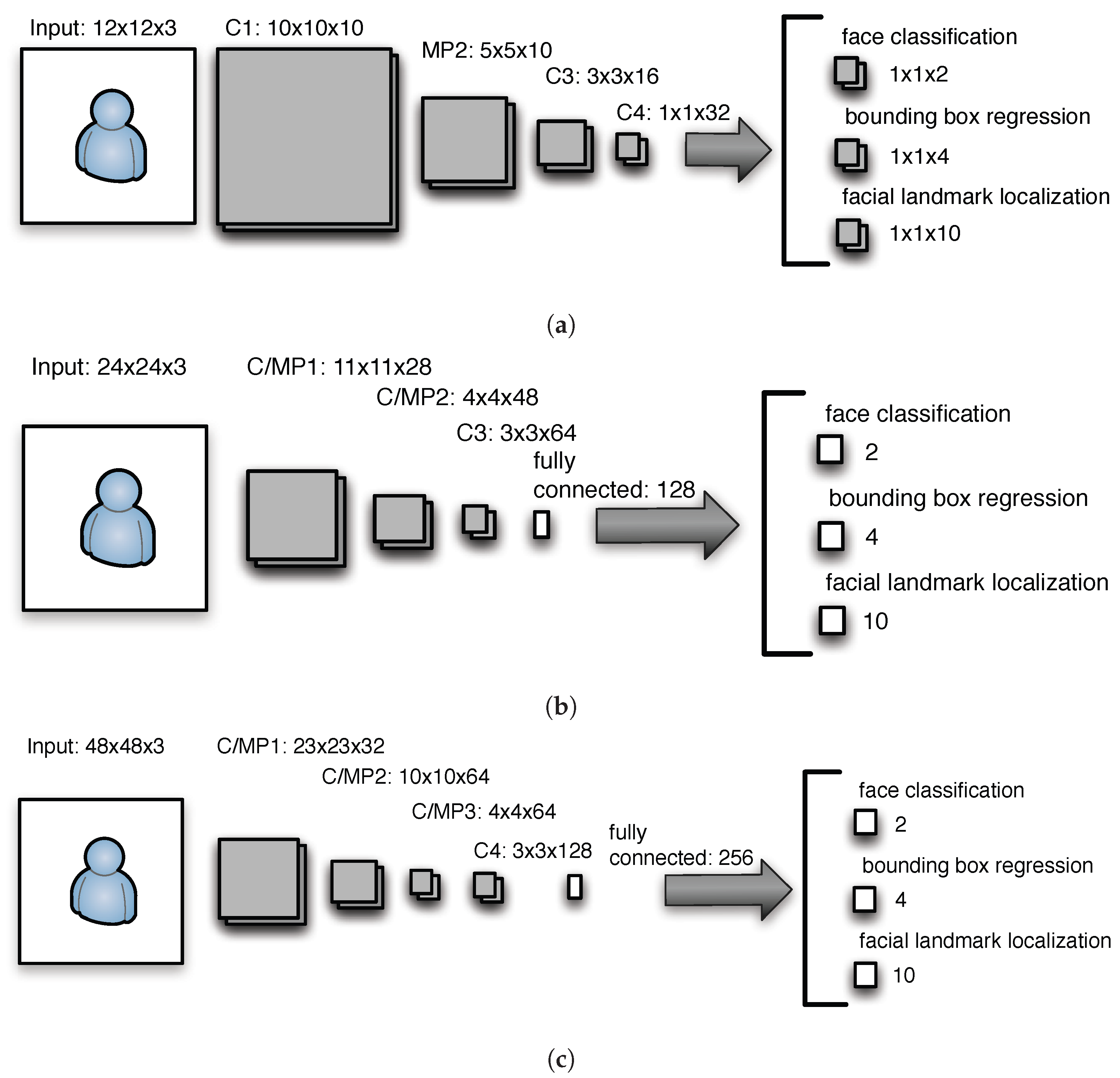
2.2.2. Multi-Task Cascaded Convolutional Networks
Proposal Network (P-Net)
Refine Network (R-Net)
Output Network or (O-Net)
2.2.3. Face Recognition Model Based on CNN
2.2.4. MobileNets for Lightweight CNNs
Regular Convolution
Depthwise Convolution
Pointwise Convolution
Parameters and Computing Effort
2.3. Internet-of-Things and Blockchains
2.4. Artificial Intelligence and Blockchains
2.5. Artificial Intelligence, Blockchains, and Internet-of-Things
2.6. Approaches Similar to This Work
2.7. The Newly Proposed Approach
3. Use Case and Architecture
3.1. Use Case
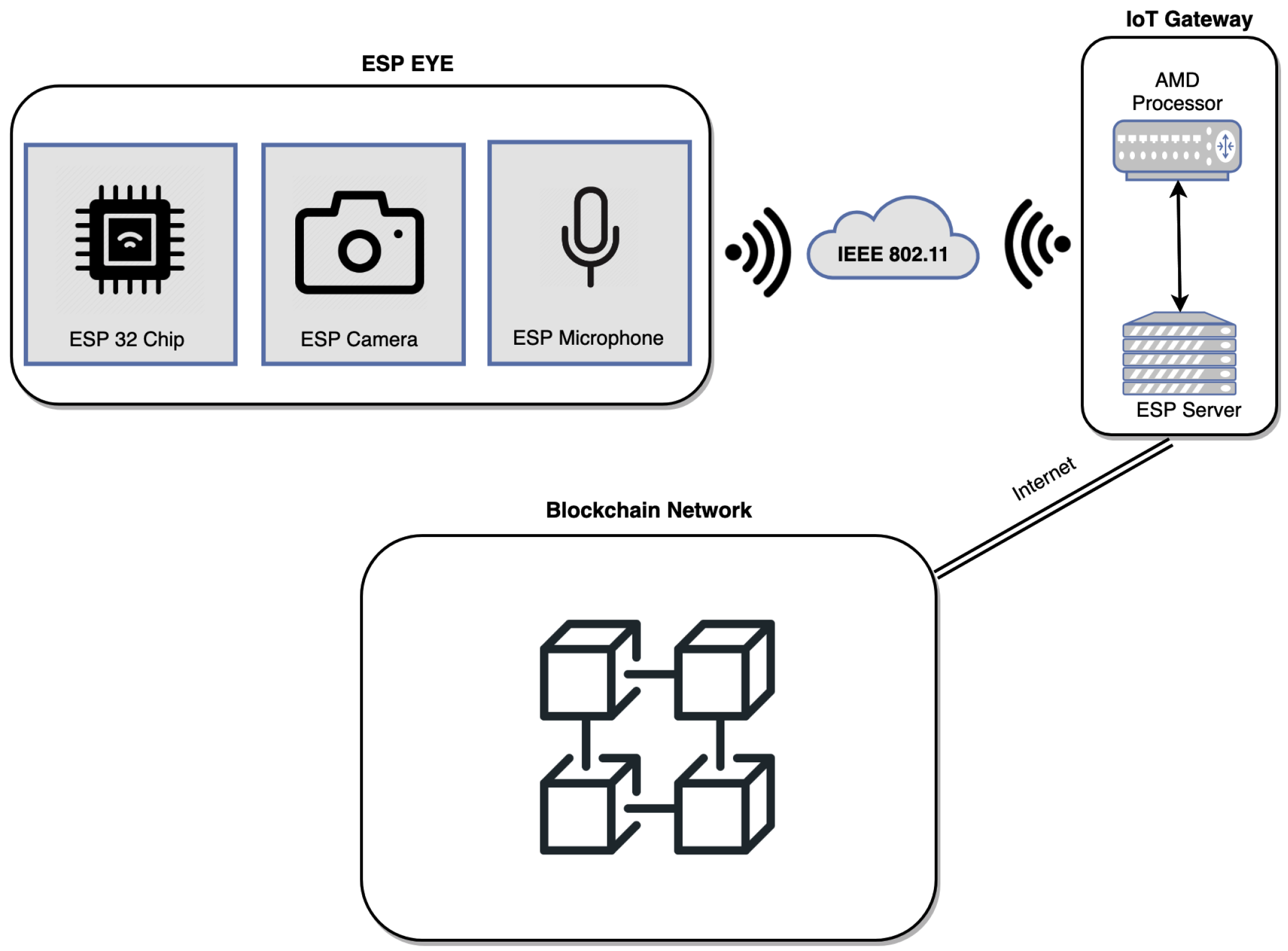
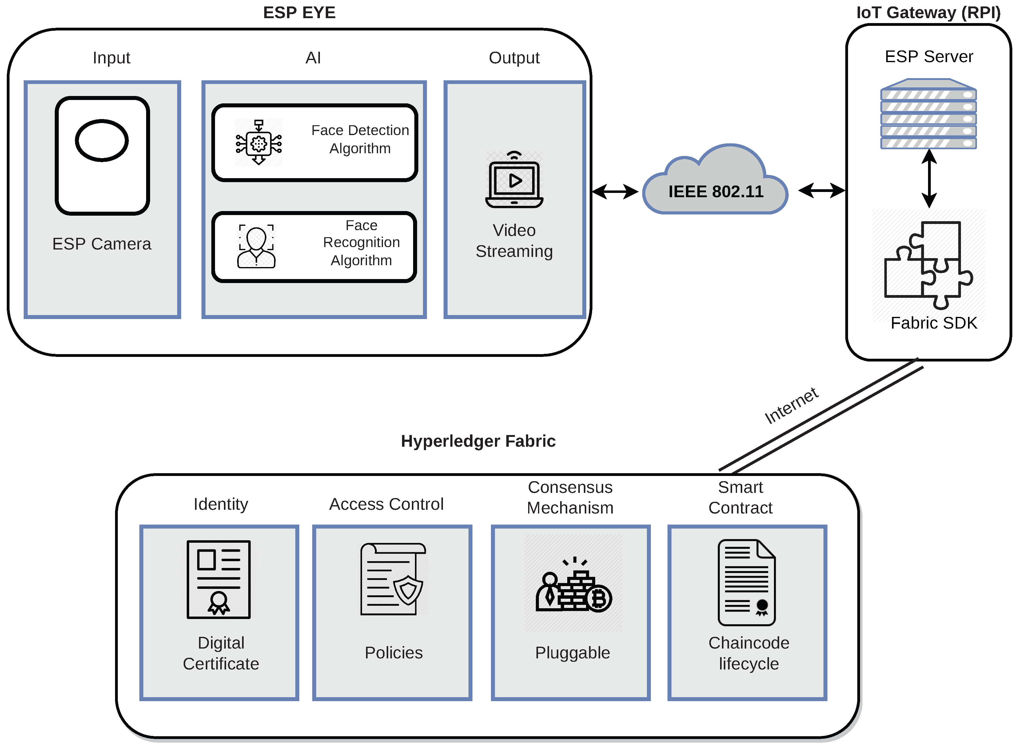
3.2. Architecture
3.2.1. Hardware Components
3.2.2. Software Architecture
3.2.3. Communication Protocols
3.3. Implementation
3.3.1. Multi-Task Cascaded Convolutional Networks (MTCNN) with MobileNets (MN)
3.3.2. Face Recognition MobileNets (FRMN)
3.3.3. Note on MTMN and FRMN Complexity
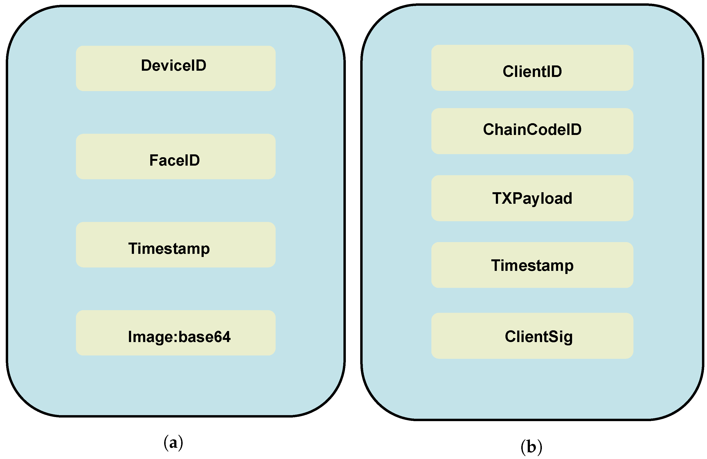
3.3.4. Esp Eye Transmission Overview
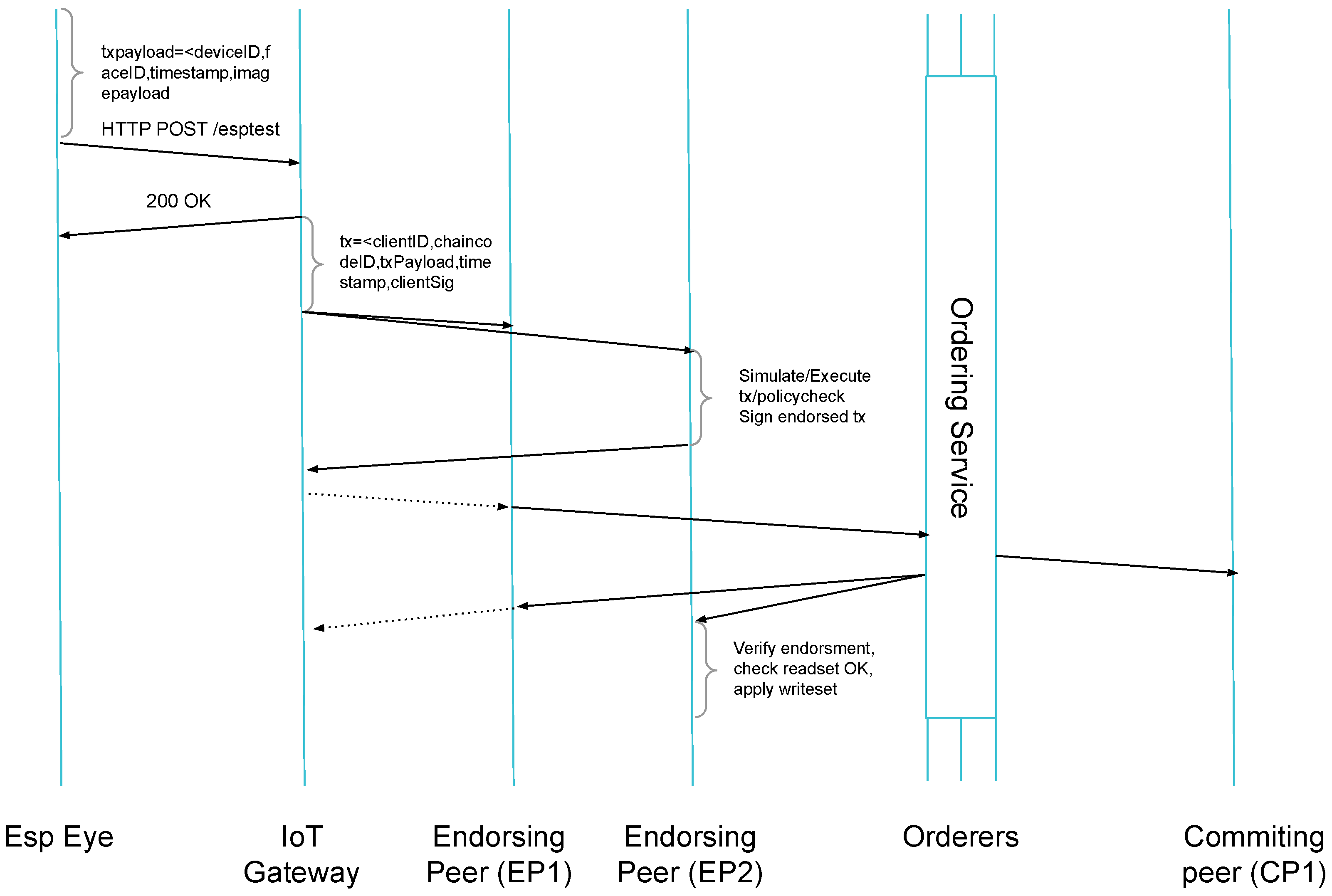
3.3.5. HLF Transaction Submission
4. Evaluation
4.1. Image Quality
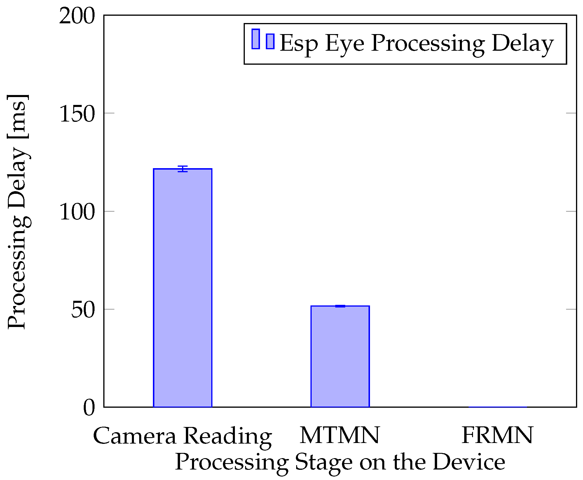
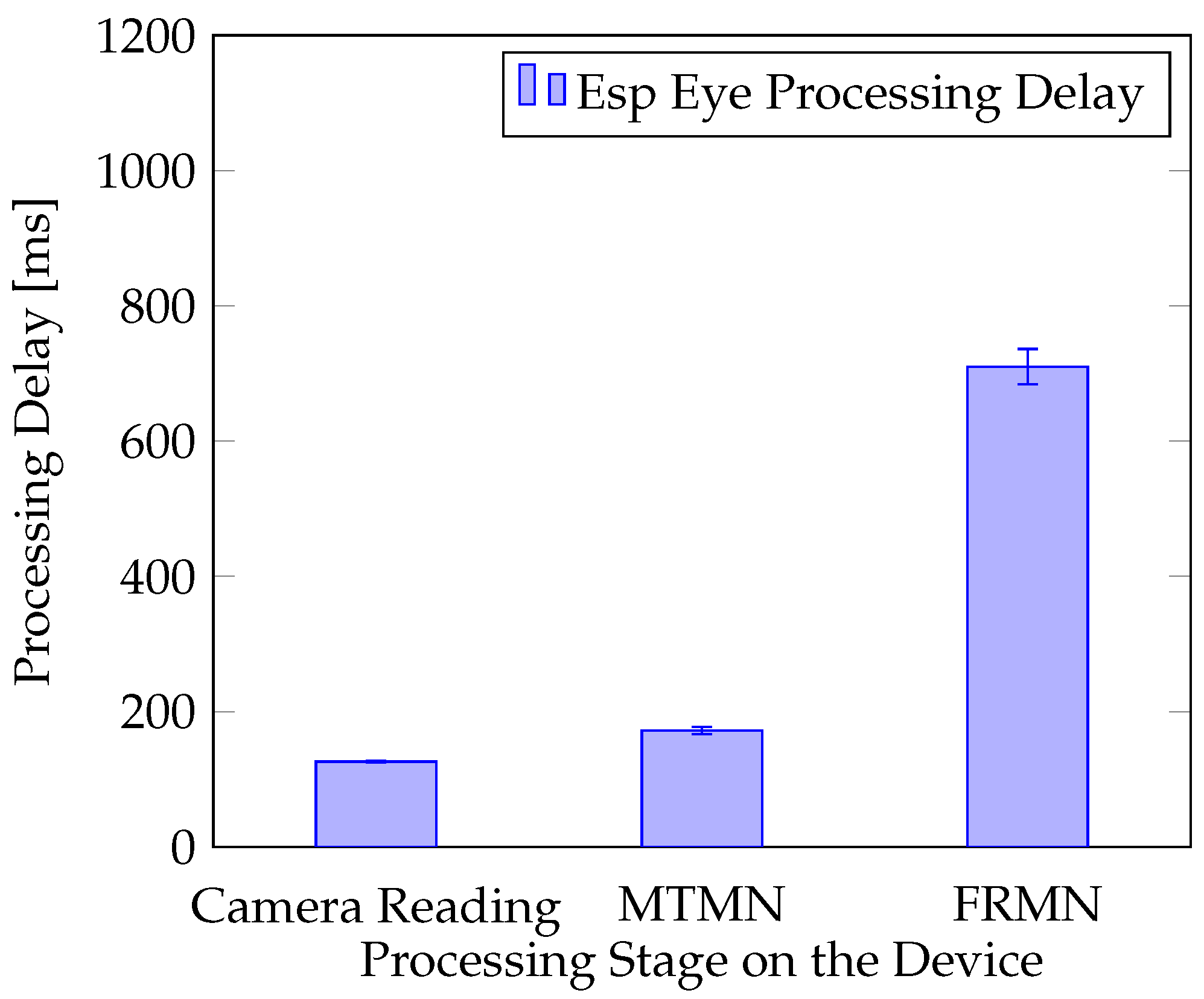
4.2. Processing Delay of Face Detection and Recognition
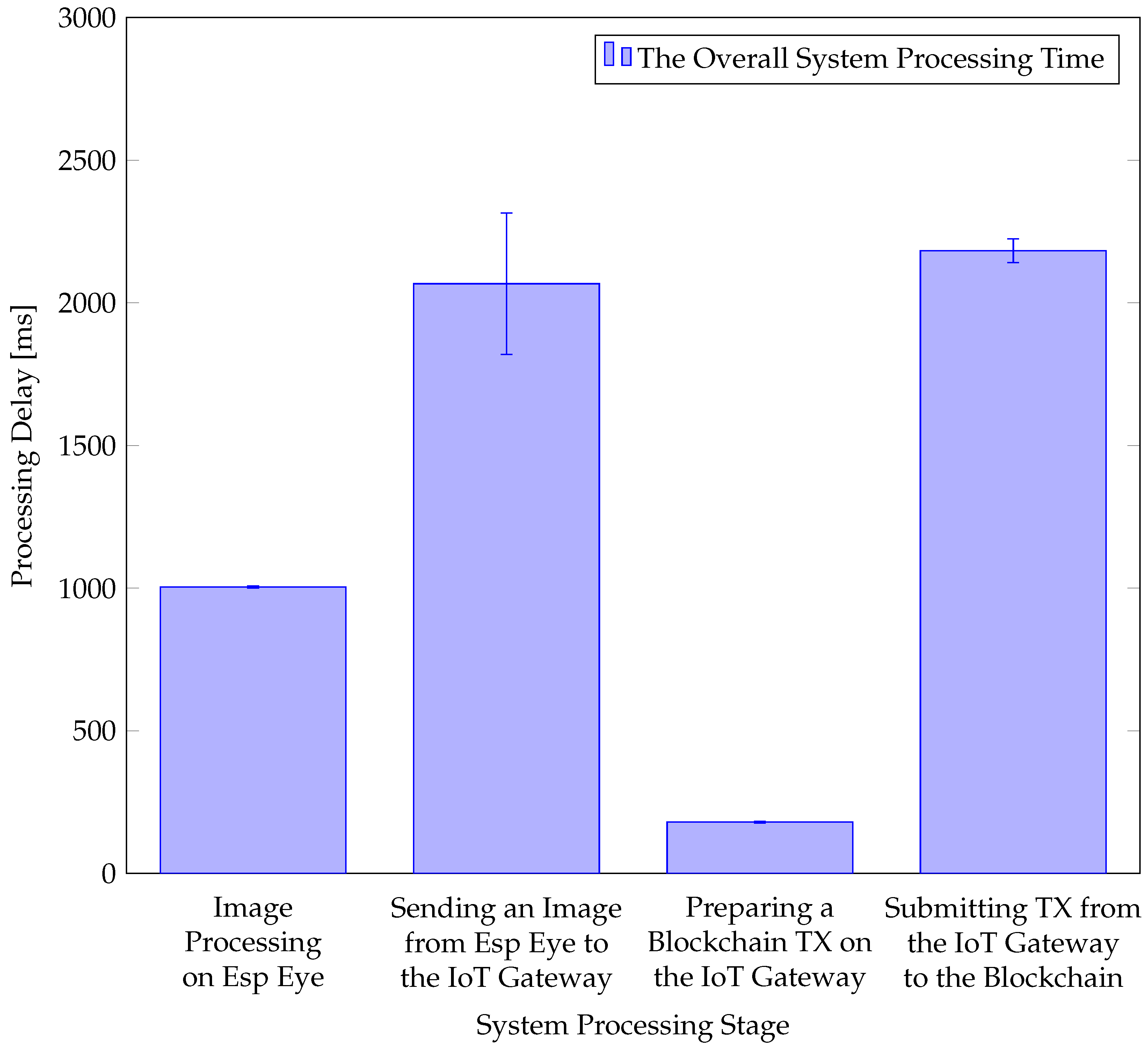
4.3. End-to-End Processing Delay
4.4. Energy Efficiency of Esp Eye
5. Summary and Future Work
- 1.
- All face descriptors of recognized faces are hard-encoded on Esp Eye devices.
- 2.
- The HLF Transaction (TX) signing is not performed directly on Esp Eye devices, since it is delegated to the IoT Gateway device supporting this process on behalf of the sensor.
- 1.
- The face descriptor management will allow an IoT device to retrieve a remote directory of recognized faces.
- 2.
- Porting the HLF Software Development Kit (SDK) to IoT devices will enable an HLF TX submission directly from IoT devices.
Author Contributions
Funding
Data Availability Statement
Conflicts of Interest
References
- Atlam, H.F.; Walters, R.J.; Wills, G.B. Intelligence of Things: Opportunities Challenges. In Proceedings of the 3rd Cloudification of the Internet of Things (CIoT’18), Paris, France, 2–4 July 2018; pp. 1–6. [Google Scholar] [CrossRef]
- Espressif Systems. ESP-EYE Development Board. Available online: https://www.espressif.com/en/products/devkits/esp-eye/overview (accessed on 10 December 2020).
- Raspberry Pi Foundation Group. Raspberry Pi 3 Model B. Available online: https://www.raspberrypi.org/products/raspberry-pi-3-model-b (accessed on 2 October 2019).
- Banafa, A. IoT and Blockchain Convergence: Benefits and Challenges. IEEE Internet-of-Things Newsletter. Available online: https://iot.ieee.org/newsletter/january-2017/iot-and-blockchain-convergence-benefits-and-challenges.html (accessed on 25 January 2022).
- Kolias, C.; Kambourakis, G.; Stavrou, A.; Voas, J. DDoS in the IoT: Mirai and Other Botnets. IEEE Comput. 2017, 50, 80–84. [Google Scholar] [CrossRef]
- Valenta, M.; Sandner, P. Comparison of Ethereum, Hyperledger Fabric and Corda. 2017. Available online: http://explore-ip.com/2017_Comparison-of-Ethereum-Hyperledger-Corda.pdf (accessed on 29 December 2021).
- Androulaki, E.; Barger, A.; Bortnikov, V.; Cachin, C.; Christidis, K.; De Caro, A.; Enyeart, D.; Ferris, C.; Laventman, G.; Manevich, Y.; et al. Hyperledger Fabric: A Distributed Operating System for Permissioned Blockchains. In Proceedings of the 13th EuroSys Conference, EuroSys 2018, Porto, Portugal, 23–26 April 2018. [Google Scholar] [CrossRef]
- Rafati-Niya, S.; Schiller, E.; Cepilov, I.; Stiller, B. BIIT: Standardization of Blockchain-based I2oT Systems in the I4 Era. In Proceedings of the IEEE/IFIP Network Operations and Management Symposium (NOMS 2020), Budapest, Hungary, 20–24 April 2020; pp. 1–9. [Google Scholar] [CrossRef]
- Schiller, E.; Rafati-Niya, S.; Surbeck, T.; Stiller, B. Scalable Transport Mechanisms for Blockchain IoT Applications. In Proceedings of the 44th IEEE LCN Symposium on Emerging Topics in Networking (LCN Symposium), Osnabrueck, Germany, 14–17 October 2019; pp. 34–41. [Google Scholar] [CrossRef]
- Schiller, E.; Esati, E.; Niya, S.R.; Stiller, B. Blockchain on MSP430 with IEEE 802.15.4. In Proceedings of the 2020 IEEE 45th Conference on Local Computer Networks (LCN), Sydney, Australia, 16–19 November 2020; pp. 345–348. [Google Scholar]
- Atlam, H.F.; Azad, M.A.; Alzahrani, A.G.; Wills, G. A Review of Blockchain in Internet of Things and AI. Big Data Cogn. Comput. 2020, 4, 28. [Google Scholar] [CrossRef]
- Singh, S.K.; Rathore, S.; Park, J. BlockIoTIntelligence: A Blockchain-enabled Intelligent IoT Architecture with Artificial Intelligence. Future Gener. Comput. Syst. 2019, 110, 721–743. [Google Scholar] [CrossRef]
- Singh, S.; Sharma, P.K.; Yoon, B.; Shojafar, M.; Cho, G.H.; Ra, I.H. Convergence of Blockchain and Artificial Intelligence in IoT Network for the Sustainable Smart City. Sustain. Cities Soc. 2020, 63, 102364. [Google Scholar] [CrossRef]
- Parker, B.; Bach, C. The Synthesis of Blockchain, Artificial Intelligence and Internet of Things. Eur. J. Eng. Technol. Res. 2020, 5, 588–593. [Google Scholar] [CrossRef]
- Espressif Systems. ESP-WHO Platform. Available online: https://github.com/espressif/esp-who (accessed on 19 September 2020).
- Abedin, S.F.; Alam, M.G.R.; Haw, R.; Hong, C.S. A System Model for Energy Efficient Green-IoT Network. In Proceedings of the International Conference on Information Networking (ICOIN’15), Siem Reap, Cambodia, 12–14 January 2015; pp. 177–182. [Google Scholar] [CrossRef]
- Tang, J.; Sun, D.; Liu, S.; Gaudiot, J. Enabling Deep Learning on IoT Devices. Computer 2017, 50, 92–96. [Google Scholar] [CrossRef]
- Gopinath, S.; Ghanathe, N.; Seshadri, V.; Sharma, R. Compiling KB-Sized Machine Learning Models to Tiny IoT Devices. In Proceedings of the 40th ACM SIGPLAN Conference on Programming Language Design and Implementation (PLDI’19), Phoenix, AZ, USA, 22–26 June 2019; pp. 79–95. [Google Scholar] [CrossRef]
- Lin, J.; Chen, W.M.; Lin, Y.; Cohn, J.; Gan, C.; Han, S. Mcunet: Tiny deep learning on iot devices. arXiv 2020, arXiv:2007.10319. [Google Scholar]
- Ackerman, D. System Brings Deep Learning to Internet of Things Devices. Available online: https://news.mit.edu/2020/iot-deep-learning-1113 (accessed on 10 December 2020).
- Zhang, K.; Zhang, Z.; Li, Z.; Qiao, Y. Joint Face Detection and Alignment Using Multitask Cascaded Convolutional Networks. IEEE Signal Process. Lett. 2016, 23, 1499–1503. [Google Scholar] [CrossRef]
- Howard, A.G.; Zhu, M.; Chen, B.; Kalenichenko, D.; Wang, W.; Weyand, T.; Andreetto, M.; Adam, H. MobileNets: Efficient Convolutional Neural Networks for Mobile Vision Applications. arXiv 2017, arXiv:cs.CV/1704.04861. [Google Scholar]
- Shang, S.; Liu, H.; Qu, Q.; Li, G.; Cao, J. FRMN-A Face Recognition Model Based on Convolutional Neural Network. In Proceedings of the IOP Conference Series: Materials Science and Engineering, Hunan, China, 17–18 May 2019; Volume 585, p. 012101. [Google Scholar]
- LeCun, Y.; Jackel, D.L.; Bottou, L.; Cortes, C.; Denker, J.S.; Drucker, H.; Guyon, I.; Muller, U.A.; Sackinger, E.; Simard, P.; et al. Learning Algorithms for Classification: A Comparison on Handwritten Digit Recognition. In Neural Networks: The Statistical Mechanics Perspective; World Scientific: Singapore, 1995; pp. 261–276. [Google Scholar]
- Lecun, Y.; Bottou, L.; Bengio, Y.; Haffner, P. Gradient-based Learning Applied to Document Recognition. Proc. IEEE 1998, 86, 2278–2324. [Google Scholar] [CrossRef]
- Adelson, E.H.; Anderson, C.H.; Bergen, J.R.; Burt, P.J.; Ogden, J.M. Pyramid Methods in Image Processing. RCA Eng. 1984, 29, 33–41. [Google Scholar]
- Sandler, M.; Howard, A.G.; Zhu, M.; Zhmoginov, A.; Chen, L. Mobilenetv2: Inverted Residuals and Linear Bottlenecks: Mobile Networks for Classification, Detection and Segmentation. arXiv 2018, arXiv:1801.04381. [Google Scholar]
- Sandler, M.; Howard, A.; Zhu, M.; Zhmoginov, A.; Chen, L.C. Mobilenetv2: Inverted residuals and linear bottlenecks. In Proceedings of the IEEE Conference on Computer Vision and Pattern Recognition, Salt Lake City, UT, USA, 18–22 June 2018; pp. 4510–4520. [Google Scholar]
- Rafati Niya, S.; Schiller, E.; Stiller, B. Architectures for Blockchain-IoT Integration. In Communication Networks and Service Management in the Era of Artificial Intelligence and Machine Learning; Zincir-Heywood, N., Diao, Y., Mellia, M., Eds.; IEEE Press Series on Networks and Service Management; Wiley-IEEE Press: New York, NY, USA, 2021; pp. 100–137. [Google Scholar]
- Waheed, N.; He, X.; Ikram, M.; Usman, M.; Hashmi, S.S.; Usman, M. Security and Privacy in IoT Using Machine Learning and Blockchain: Threats and Countermeasures. ACM Comput. Surv. 2020, 53, 122. [Google Scholar] [CrossRef]
- Dinh, T.N.; Thai, M.T. AI and Blockchain: A Disruptive Integration. Computer 2018, 51, 48–53. [Google Scholar] [CrossRef]
- Liu, L.; Feng, J.; Pei, Q.; Chen, C.; Ming, Y.; Shang, B.; Dong, M. Blockchain-Enabled Secure Data Sharing Scheme in Mobile-Edge Computing: An Asynchronous Advantage Actor–Critic Learning Approach. IEEE Internet Things J. 2021, 8, 2342–2353. [Google Scholar] [CrossRef]
- Quadri, S.A.I.; Sathish, P. IoT based Home Automation and Surveillance System. In Proceedings of the International Conference on Intelligent Computing and Control Systems (ICICCS’17), Madurai, India, 15–16 June 2017; pp. 861–866. [Google Scholar] [CrossRef]
- LoRa Alliance. A Technical Overview of LoRa and LoRaWAN. Available online: https://lora-alliance.org/portals/0/documents/whitepapers/LoRaWAN101.pdf (accessed on 17 May 2019).
- Schiller, E.; Esati, E.; Stiller, B. IoT-based Access Management Supported by AI and Blockchains. In Proceedings of the 17th International Conference on Network and Service Management (CNSM’21), Izmir, Turkey, 25–29 October 2021; pp. 350–354. [Google Scholar] [CrossRef]
- Gorenflo, C.; Lee, S.; Golab, L.; Keshav, S. FastFabric: Scaling Hyperledger Fabric to 20,000 Transactions per Second. In Proceedings of the IEEE International Conference on Blockchain and Cryptocurrency (ICBC’19), Seoul, Korea, 14–17 May 2019; pp. 455–463. [Google Scholar] [CrossRef]
- Scheid, E.J.; Lakic, D.; Rodrigues, B.B.; Stiller, B. PleBeuS: A Policy-based Blockchain Selection Framework. In Proceedings of the NOMS 2020–2020 IEEE/IFIP Network Operations and Management Symposium, Budapest, Hungary, 20–24 April 2020; pp. 1–8. [Google Scholar] [CrossRef]
- Pezoa, F.; Reutter, J.L.; Suarez, F.; Ugarte, M.; Vrgoč, D. Foundations of JSON Schema; International World Wide Web Conferences Steering Committee: Geneva, Switzerland, 2016; pp. 263–273. [Google Scholar] [CrossRef]
- Esati, E. IoT-Based Access Management, GitHub Repository. Available online: https://github.com/eesati/Master-Thesis (accessed on 25 January 2022).
- Tilkov, S.; Vinoski, S. Node. js: Using JavaScript to Build High-Performance Network Programs. IEEE Internet Comput. 2010, 14, 80–83. [Google Scholar] [CrossRef]
- Josefsson, S. The BASE16, BASE32, and BASE64 Data Encodings; Technical Report, IETF RFC 4648; The Internet Society: Reston, VA, USA, October 2006. [Google Scholar]
- Badamasi, Y.A. The Working Principle of an Arduino. In Proceedings of the 11th International Conference on Electronics, Computer and Computation (ICECCO’14), Abuja, Nigeria, 29 September–1 October 2014; pp. 1–4. [Google Scholar] [CrossRef]


| CNN Stage | Regular | MobileNet | ||
|---|---|---|---|---|
| Parameters | Operations (MAdds) | Parameters | Operations (MAdds) | |
| P-Net | 6318 | 116,352 | 327 | 20,362 |
| R-Net | 25,139 | 2,095,680 | 550 | 309,276 |
| O-Net | 135,168 | 15,951,872 | 1310 | 2,121,504 |
Publisher’s Note: MDPI stays neutral with regard to jurisdictional claims in published maps and institutional affiliations. |
© 2022 by the authors. Licensee MDPI, Basel, Switzerland. This article is an open access article distributed under the terms and conditions of the Creative Commons Attribution (CC BY) license (https://creativecommons.org/licenses/by/4.0/).
Share and Cite
Schiller, E.; Esati, E.; Stiller, B. IoT-Based Access Management Supported by AI and Blockchains. Electronics 2022, 11, 2971. https://doi.org/10.3390/electronics11182971
Schiller E, Esati E, Stiller B. IoT-Based Access Management Supported by AI and Blockchains. Electronics. 2022; 11(18):2971. https://doi.org/10.3390/electronics11182971
Chicago/Turabian StyleSchiller, Eryk, Elfat Esati, and Burkhard Stiller. 2022. "IoT-Based Access Management Supported by AI and Blockchains" Electronics 11, no. 18: 2971. https://doi.org/10.3390/electronics11182971
APA StyleSchiller, E., Esati, E., & Stiller, B. (2022). IoT-Based Access Management Supported by AI and Blockchains. Electronics, 11(18), 2971. https://doi.org/10.3390/electronics11182971