Abstract
A simple data-aided carrier synchronization scheme is proposed for variable modulation (VM) communication systems under the initial conditions of a low signal-to-noise ratio (SNR) and normalized carrier frequency offset (CFO) symbol rate of 20%. The proposed carrier synchronization scheme is simplified into two steps; a reconfigurable L&R (RLR) algorithm and pilot-aided (PA) phase linear interpolation algorithm is applied for carrier frequency recovery (CFR) and carrier phase recovery (CPR), respectively. Furthermore, the autocorrelation values of multi-pilot blocks are superimposed to improve the accuracy of the CFR algorithm, and the algorithm formulas are decomposed and modularized to simplify the implementation complexity of the RLR algorithm. Simulation results show that the RLR algorithm can track and lock the CFO up to a 33.2% symbol rate and reduce the CFO to 0.024%. The bit error rate (BER) performance of the carrier synchronization scheme almost coincides with the theoretical curve results. Comparison of hardware complexity shows that the multiplication resource consumption can be reduced by at least 72.47%.
1. Introduction
The proliferation of bandwidth caused by the factors of low-order modulation, spatial channel spectrum resource constraint, and increasing transmission inefficiency are becoming increasingly prominent. To meet the demand of payload data transmission, we can fix the situation in three ways: channel band utilization, power consumption utilization, and signal power utilization. The data transmission efficiency is usually improved by increasing the channel band utilization. The existing satellite–ground link data transmission system is often based on the modulation method applicable to the lowest inter-satellite link gain for data transmission, which will lead to the waste of satellite–ground channel resources and satellite resources. To make full use of the satellite link resources and improve the data transmission efficiency, a variable modulation (VM) system is proposed. The VM system can switch various Modulation modes according to the gain of inter-satellite links.
The receiver of a VM communication system usually adopts a low-cost oscillator, which introduces large initial carrier frequency offset (CFO) to the process of digital transmission for various reasons, such as system oscillation frequency error and Doppler shift, while the receiver of a VM communication system usually needs to achieve high phase estimation accuracy with a low signal-to-noise ratio (SNR). Carrier synchronization is often used for carrier frequency offset recovery (CFR) and carrier phase recovery (CPR). A CFR algorithm consists of a data-aided CFR algorithm and a non-data-aided CFR algorithm, and a CPR algorithm consists of a data-aided CPR algorithm and a non-data-aided CPR algorithm. The commonly used data-aided CFR algorithms are Kay, C&S, M&M, Jiang, Fitz, and L&R algorithms, and the widely used data-aided CPR algorithms are pilot-aided (PA) phase linear interpolation algorithms.
The existing CFR scheme requires at least two steps, including initial frequency recovery, the coarse CFR algorithm, and the fine CFR algorithm. The CPR scheme requires at least one step, including coarse CPR and fine CPR. The four-step carrier synchronization scheme is proposed in [1], including the M&M algorithm for initial CFR, the improved L&R algorithm for coarse CFR, the pilot block interpolation for fine CFR, and the phase difference of the pilot symbols for CPR. A three-step carrier synchronization scheme is proposed in [2], which uses a Delay & Multiply (D&M) algorithm for coarse CFR, then an L&R algorithm for fine CFR, and the PA phase linear interpolator for CPR. The three-step carrier synchronization scheme is proposed, utilizing the Fitz algorithm for coarse CFR, the simple pilot block correlation algorithm for fine CFR, and the PA phase linear interpolator for CPR in [3,4]. The three-step carrier synchronization scheme that adopts the M&M algorithm for coarse CFR, the simple pilot block correlation algorithm [5] for fine CFR, and the pilot-aided block for CPR is proposed in [6]. The study of the features of the application of the coarse frequency synchronization algorithm in [7] reduces the synchronization time, but it does not reduce the complexity of the scheme. A three-step scheme is given in [8]; its purpose is not to simplify the scheme, but to optimize performance. Among them, the alternative carrier synchronization scheme proposed in [3] is less complex compared with [1,2,6], but the scheme is still more complicated.
In this paper, a simplified data-aided carrier synchronization scheme for the VM system is proposed, where the CFO estimation algorithm utilizes the RLR algorithm, and the CPR utilizes the PA phase linear interpolation algorithm. In comparison with the Kay [9], C&S [10], M&M [11], Jiang [12], Fitz [13], and L&R algorithms [14,15,16], the RLR algorithm is reconfigurable with higher accuracy. The residual frequency offset and residual phase offset can be reduced to the correctable range of the CPR algorithm. The proposed carrier synchronization scheme is simulated under the condition that the symbol rate is 25 Mbaud and the CFO is 20% symbol rate, and its performance almost coincides with the theoretical curve results. In addition, its operating frequency can be up to 200 MHz, with less resource consumption and less complexity of implementation.
2. Conventional Carrier Synchronization Algorithm
2.1. Conventional Carrier Synchronization Scheme
As shown in Figure 1, the physical layer (PL) frame of the VM system consists of three parts: the frame header, the data block, and the pilot block. The physical layer header (PLHEADER) consists of 26 symbols of start of frame (SOF) code and 64 symbols of physical layer signaling (PLS) code (PLSCODE). The data block consists of 16 slots, each with 90 symbols. The pilot block consists of 36 pilot symbols, and each unmodulated pilot symbol can be defined as and . The conventional carrier synchronization scheme is illustrated in Figure 2, which consists of three parts: coarse CFR, fine CFR, and CPR, and the scheme is more complicated [13].

Figure 1.
Frame structure.
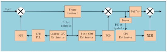
Figure 2.
Conventional carrier synchronization scheme.
2.2. Proposed Carrier Synchronization Scheme
The frame header position needs to be detected before the carrier synchronization algorithm. Therefore, frame header detection is the key to the whole carrier synchronization scheme. As shown in Figure 3, the proposed carrier synchronization scheme is simplified from three steps to two steps. Differential detection of the SOF and PLSCODE algorithm is adopted to detect the frame header and calculate the location of the pilot block, the distance between pilot blocks, and the index according to the position of the frame header. The RLR algorithm is used to calculate the CFO, the loop filter, and the numerically controlled oscillator (NCO), which are used for CFO compensation. The RLR algorithm locked at a 33.2% CFO with high accuracy. A PA phase linear interpolation algorithm is applied to CPR.
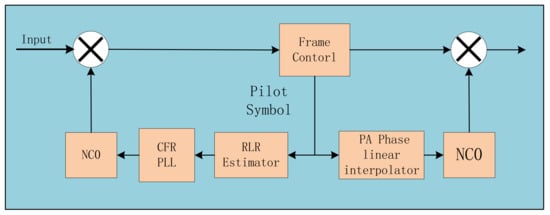
Figure 3.
Proposed carrier synchronization scheme.
3. Proposed Carrier Synchronization Algorithm
3.1. Frame Header Detection Algorithm
The commonly used frame header detection algorithm is the differential detection of the SOF and PLSCODE [17]. The algorithm first performs differential operations on the input signal, then correlates on both the SOF and PLSCODE differentially using 89 registers and 57 taps. Finally, the outputs of the two parts are, respectively, added and subtracted to produce two values, the maximum of which is the final output of this correlation circuit. When the SOF is detected, we get:
where , represents the noise, is the symbol sent, is the symbol received, is the SOF register tap, and is the CFO. is the conjugate of .
When the PLSCODE is detected, we get:
where , denotes the noise, is the PLSCODE register tap, and is 0 or 1.
When the frame header is detected, the correlation detector output of the SOF and PLSCODE can be expressed as:
where is the noise. The correlation value is insensitive to the CFO and phase offset . When the maximum correlation value is about 57, it indicates that the frame header is detected.
3.2. Carrier Frequency Recovery Algorithm
The data-aided CFO estimation algorithm is implemented based on pilot autocorrelation in the VM system. The commonly used data-aided CFO estimation algorithms are Kay, C&S, M&M, Jiang, Fitz, and L&R. Figure 4 shows the CFO estimation range of different algorithms using 36 pilot symbols. In [3], when the CFO estimation algorithm needs to satisfy the two conditions that the CFO can be tracked and locked to 20% of the symbol rate and the algorithm has high accuracy, only D&M, L&R, Fitz, M&M, and improved M&M algorithms can meet this need, but the complexity of D&M, M&M, and Fitz algorithms is higher compared with the L&R algorithm. Therefore, the L&R algorithm is more suitable for CFR. When , the L&R algorithm can track the locked CFO up to 33.2% of the symbol rate.
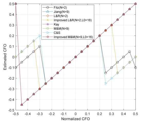
Figure 4.
Estimation range of different CFO estimation algorithms.
is the de-modulated pilot signal, and the autocorrelation function is expressed as:
where represents the number of pilot symbols, .
The expression of the L&R algorithm [7] is:
To simplify the complexity of the L&R algorithm implementation and to modularize each function, the RLR algorithm is proposed in this paper, in which the conjugate of is redefined as:
is the conjugate of . Then, can be expressed as:
where . The sub-autocorrelation function , with , can be written as:
The sum of different intervals’ autocorrelation values of the demodulated signal in the pilot block can be written as:
Then:
Figure 5 shows the block diagram of function . The signal can be used to indicate whether the sub-autocorrelation function module is in the operation. According to different conditions, the signal can be flexibly controlled in this algorithm to implement the RLR architecture under different parameters, N, in which can be defined as:
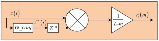
Figure 5.
Sub-autocorrelation function module.
The estimation accuracy of the algorithm can be improved by superimposing consecutive pilot blocks. The frequency estimate value of the RLR algorithm is:
where is the autocorrelation function of the pilot block. Then:
As shown in Figure 6, the structure of the CFO estimation algorithm is mainly composed of Unit1, Unit2, Unit3, Unit4, and Unit5. Unit1 realizes the autocorrelation function at different intervals; Unit2 accumulates the autocorrelation values of different intervals; Unit3 calculates the cumulative sum of the autocorrelation values of the pilot block with different intervals; Unit4 realizes the cumulative autocorrelation values of multiple pilot blocks; and Unit5 estimates the CFO. Assuming that the number of cumulative autocorrelations of multiple pilot blocks is , then the accumulator loop is set from 0 to , and the signal is the enable signal of the accumulator. When the accumulator number is equal to , the cumulative autocorrelation result of multiple pilot blocks is an arctangent calculation to obtain the frequency estimate value , and the enable signal is generated to clear the accumulation value to zero. It can be seen from Unit4 that the increased resource consumption is limited. The RLR algorithm calculates the CFO and recovers the CFO through the feedback loop.
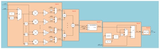
Figure 6.
Block diagram of carrier frequency offset estimation regarding RLR algorithm.
3.3. Carrier Phase Recovery Algorithm
After the CFO compensation, residual frequency offset and residual phase offset still exist in the signal, so residual phase estimation and phase compensation are also needed. In this paper, the PA phase linear interpolator algorithm is used for phase estimation and compensation, and the phase error detector uses the pilot block to estimate the phase error. The expression is:
where is the input sequence of the CPR, is the known pilot sequence, and is the conjugate of . The PA phase linear interpolator algorithm implements linear interpolation between the preamble pilot block and the current pilot block, which is shown in Figure 7. The phase linear interpolation expression is:
where represents the estimated phase of the data symbol between the pilot block and the pilot block, is the phase offset evaluation value of the pilot block, and denotes the number of symbols between the block and the pilot block. The estimated range of the phase error detector should be between .
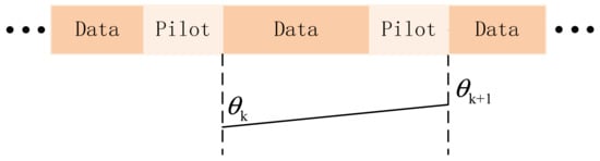
Figure 7.
Pilot-aided (PA) phase linear interpolator.
As shown in Figure 8, the implementation structure of the CPR algorithm is composed of Unit6 and Unit7. The de-modulated pilot block is selected to accumulate. Moreover, the current pilot block phase is calculated in Unit6. The phase difference value between the current pilot block phase and the preamble block is calculated. Moreover, the phase difference is limited between in Unit7. The index value and the distance between the preamble block and the current pilot block are used to calculate a linear interpolation , which is limited to between , and the linear interpolation is input to the DDS for feedforward compensation.
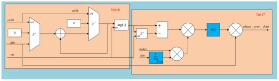
Figure 8.
Block diagram of CPR implementation.
4. Carrier Synchronization Scheme Simulation and Hardware Implementation
4.1. Carrier Synchronization Scheme Simulation and Performance Analysis
Under the conditions of pilot-aided environment of symbol rate of 25 Mbaud, initial CFO of 5 MHz, initial phase offset of , and a code length of 8160, the proposed carrier synchronization scheme is simulated with QPSK, 8PSK, 16APSK, and 32APSK BER curves. The multiplication resource consumption of the RLR algorithm is proportional to the parameter N, which is 2 × N. The larger the value of N, the more the multiplication resource is consumed, the smaller the capture range, and the higher the algorithm accuracy. Therefore, combining various factors, the valid signal can be controlled to make the RLR architecture work in the N = 2 architecture. When the carrier frequency offset is reduced to a smaller range, the valid signal can be controlled to make the RLR architecture work in the N = 15 architecture so that the carrier frequency offset accuracy can reach the carrier phase offset.
The number of superimposed pilot segments will affect the precision of the RLR algorithm. The larger the superimposed blocks, the higher the accuracy. In Figure 9, the root mean square error (RMSE) changes little when the number of superimposed blocks is less than 64. In the four modulations, the RMSE is almost the smallest when the number of superimposed blocks is L = 16 or L = 32. In this paper, the RLR algorithm with 16 superimposed blocks is selected for CFR.
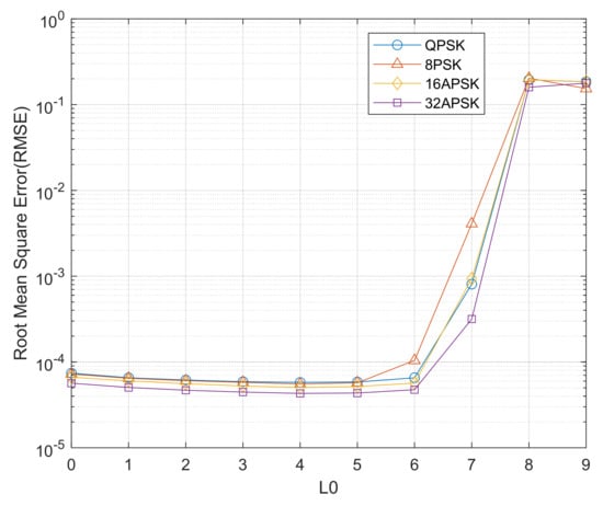
Figure 9.
Effect of the number of superimposed pilot blocks on the performance of the RLR algorithm.
The differential detection of the SOF and PLSCODE algorithm detects the frame header and deduces the position of the pilot block. Furthermore, CFR reduces the CFO to 0.024% using 36 pilot symbols. The PA phase linear interpolator algorithm can correct the residual frequency deviation and phase deviation. As shown in Figure 10, the BER curve of the proposed carrier synchronization scheme almost coincides with the theoretical curve under four different modulations, and the demodulation performance loss is close to 0 dB. Therefore, the proposed carrier synchronization scheme is reliable under the condition of a low SNR and a normalized CFO of 20% of the symbol rate.
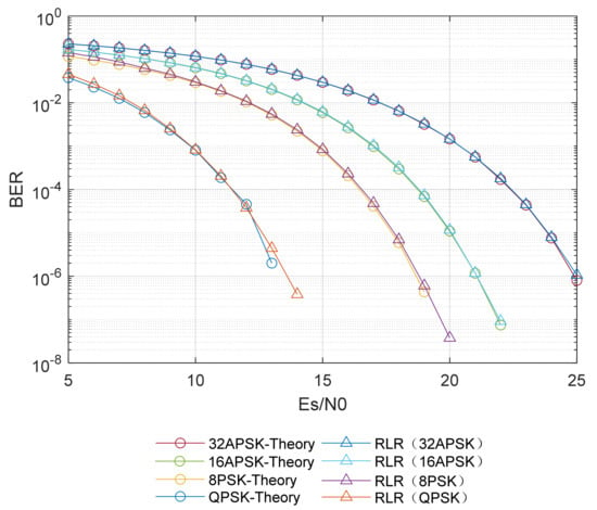
Figure 10.
Simulation of BER curves of the proposed carrier synchronization scheme.
The hardware complexity of the conventional carrier frequency synchronization scheme and the proposed carrier frequency synchronization scheme are compared in Table 1, where the proposed scheme simplifies the carrier frequency synchronization scheme from two-step to one-step. According to Table 1, compared with studies [2,3,4], multiplication resource consumption can be reduced by 90.68%, 72.47%, and 90.53%, respectively.

Table 1.
Hardware complexity comparison.
4.2. Carrier Synchronization Scheme Hardware Implementation
The proposed scheme was verified in the simulation environment of vivado2017.4 and the hardware platform of xcku040-ffva1156-2-e FPGA. The resource consumption and the maximum operating frequency for different functional modules were analyzed, as shown in Table 2. Frame synchronization utilizes 1.67% DSP resources, the CFR algorithm utilizes 12.50% DSP resources, and the CPR algorithm utilizes 0.73% DSP resources. The proposed RLR architecture can be realized by controlling the valid signal.
Table 2.
Hardware utilization.
The operating frequency of the proposed scheme can be up to 200 MHz with less resource consumption and less complexity of implementation. Only 15.1% of the DSP resources are utilized.
5. Conclusions
Compared with the conventional scheme, the proposed scheme simplifies the carrier synchronization from three steps to two steps and dramatically reduces the multiplication of carrier synchronization, which is relatively simple and practical. In the pilot-aided VM system, the BER curve of the proposed carrier synchronization scheme is almost the same as the theoretical BER curve. The operating frequency of the proposed scheme can be up to 200 MHz. Therefore, it has a wide range of application prospects in high-speed equipment.
Author Contributions
Conceptualization, W.H. and Z.W.; methodology, W.H.; software, W.H.; validation, W.H. and R.M.; formal analysis, W.H.; investigation, W.H. and R.M.; resources, W.H.; data curation, W.H.; writing—original draft preparation, W.H.; writing—review and editing, M.L. and R.M.; visualization, R.M.; supervision, W.H. and Z.W.; project administration, Z.W. and W.H. All authors have read and agreed to the published version of the manuscript.
Funding
This research was funded by the Strategic Priority Research Program of the Chinese Academy of Sciences (Class A) (Subject Number: XDA153501, Sub-Subject Number: XDA15350103).
Conflicts of Interest
The authors declare no conflict of interest.
References
- Park, J.W.; Sunwoo, M.H.; Kim, P.S.; Chang, D.I. An Efficient Data-Aided Initial Frequency Synchronizer for DVB-S2. In Proceedings of the IEEE Workshop on Signal Processing Systems, Shanghai, China, 17–19 October 2007; pp. 645–650. [Google Scholar]
- Casini, E.; De Gaudenzi, R.; Ginesi, A. DVB-S2 modem algorithms design and performance over typical satellite channels. Int. J. Satell. Commun. Netw. 2004, 22, 281–318. [Google Scholar] [CrossRef]
- Oh, J.G.; Kim, J.T. An alternative carrier frequency synchronization scheme for DVB-S2 systems. In Proceedings of the International Conference on Advanced Communication Technology, Gangwon, Korea, 11–14 February 2010; pp. 529–533. [Google Scholar]
- Kim, P.; Ryu, J.-G. Carrier phase recovery for DVB-S2x standard in VL SNR channel. In Proceedings of the Advances in Communications Satellite Systems, 37th International Communications Satellite Systems Conference (ICSSC-2019), Okinawa, Japan, 1–8 November 2019. [Google Scholar]
- Barbieri, A.; Colavolpe, G. On Pilot-Symbol-Assisted Carrier Synchronization for DVB-S2 Systems. IEEE Trans. Broadcast. 2007, 53, 685–692. [Google Scholar] [CrossRef] [Green Version]
- Oh, J.G.; Kim, J.T. A simple and robust carrier frequency recovery scheme for DVB-S2 systems. IEEE Int. Symp. Consum. Electron. 2010, 15, 1–4. [Google Scholar] [CrossRef]
- Antiufrieva, L.; Ivchenko, A.; Dvorkovich, A. Features of a coarse frequency synchronization for DVB-S2X system. In Proceedings of the 2020 International Conference Engineering and Telecommunication (En&T), Dolgoprudny, Russia, 1–4 November 2020. [Google Scholar]
- Antiufrieva, L.; Iansitov, K.; Ivchenko, A.; Dvorkovich, A. Features of Frequency Synchronization Algorithms DVB-S2(X) for LEO Satellites. In Proceedings of the 2021, 23rd International Conference on Digital Signal Processing and Its Applications (DSPA), Moscow, Russia, 1–4 November 2021. [Google Scholar]
- Kay, S. A fast and accurate single frequency estimator. IEEE Trans. Acoust. Speech, Signal Process. 1989, 37, 1987–1990. [Google Scholar] [CrossRef] [Green Version]
- Chuang, J.C.-I.; Sollenberger, N.R. Burst coherent demodulation with combined symbol timing, frequency offset estimation, and diversity selection. IEEE Trans. Commun. 1991, 39, 1157–1164. [Google Scholar] [CrossRef]
- Mengali, U.; Morelli, M. Data-aided frequency estimation for burst digital transmission. IEEE Trans. Commun. 1997, 45, 23–25. [Google Scholar] [CrossRef]
- Jiang, Y.M. Synchronization and Channel Parameter Estimation in Wireless Communications; University of Maryland: College Park, MD, USA, 2000. [Google Scholar]
- Fitz, M.P. Planar filtered techniques for burst mode carrier synchronization. In Proceedings of the Global Telecommunications Conference, Phoenix, AZ, USA, 2–5 December 1991; pp. 365–369. [Google Scholar]
- Gong, F.; Shang, G.; Li, Y.; Peng, K. Initial-Estimation-Based Adaptive Carrier Recovery Scheme for DVB-S2 System. IEEE Trans. Broadcast. 2012, 58, 654–659. [Google Scholar] [CrossRef]
- Luise, M.; Reggiannini, R. Carrier frequency recovery in all-digital modems for burst-mode transmissions. IEEE Trans. Commun. 1995, 43, 1169–1178. [Google Scholar] [CrossRef]
- Sun, J.; Shi, J. A two-step frequency offset estimation algorithm using the iNET preamble in multipath fading channels. In Proceedings of the 2018 14th IEEE International Conference on Signal Processing (ICSP), Beijing, China, 12–16 August 2018; pp. 676–681. [Google Scholar]
- Zhang, Y. Research on Key Techniques of VCM/ACM in Satellite Data Transmission Link; University of Chinese Academy of Sciences: Beijing, China, 2019. [Google Scholar]
Publisher’s Note: MDPI stays neutral with regard to jurisdictional claims in published maps and institutional affiliations. |
© 2021 by the authors. Licensee MDPI, Basel, Switzerland. This article is an open access article distributed under the terms and conditions of the Creative Commons Attribution (CC BY) license (https://creativecommons.org/licenses/by/4.0/).