1. Introduction
Two main perspectives, very different from each other, have been adopted in Computer Science for information storage and handling. The ‘Knowledge Base’ (KB) perspective is interested in high-level reasoning on the available information, so as to infer implicit information or check the consistency of the information with respect to the reference domain. It is pursued by the Knowledge Representation (KR) branch of Artificial Intelligence (AI) and includes the research field of formal ontologies. The ‘Data Base’ (DB) perspective is a traditional branch of research in Computer Science interested in developing optimal data organizations aimed at efficient storage, management and retrieval. While clearly complementary, these two perspectives have traditionally been investigated separately. However, due to the increasingly pervasive use of AI solutions in many applications, it would be extremely relevant to take advantage of both.
A new opportunity for cooperation comes from the recent development of
Graph Databases, a kind of NoSQL DB aimed at optimizing element-driven data browsing rather than batch processing as in traditional relational DBs. Another difference between graph and relational DBs is that the former do not have a pre-defined schema to describe and organize the data, which obviously affects the interpretability and accessibility of the data by the applications and their interoperability. A
graph is a data structure consisting of nodes (usually representing things) and arcs connecting these nodes (usually representing relationships between things). The arcs may be directed, if they have a direction, and may have attributes or labels qualifying or quantifying the relationship. Interestingly, when the terminological part of an ontology (Tbox, reporting definitions and axioms) is considered in conjunction with the assertional part (Abox, specifying individuals or instances) the result is a so-called
Knowledge Graph (KG, a kind of KB) [
1]. Whilst the literature on ontologies often defines them as encompassing both parts, the relevant literature adopts this very definition for KGs, equating the ontology to the data model only:
“A knowledge graph is created when you apply an ontology (the data model) to a dataset of individual data points (the [...] data). In other words:
| ontology + data = knowledge graph” [2]. |
“Ontologies represent the backbone of the formal semantics of a knowledge graph. They can be seen as the data schema of the graph” [
3].
Knowledge graphs derive from “the core idea of using graphs to represent data, often enhanced with some way to explicitly represent knowledge” [
4].
“In general, a knowledge graph describes objects of interest and connections between them. […] Many practical implementations impose constraints on the links in knowledge graphs by defining a schema or ontology’ [
5].
It is clear that graph representation can be the missing link to join the two perspect ives/technologies and take the best from each. Unfortunately, formal ontologies and graph DBs refer to different graph models which cannot straightforwardly be combined together. This paper proposes a technology, called GraphBRAIN, aimed at bridging the gap between them through the following contributions:
Defining a formalism for expressing graph DB schemas, so as to allow data interpretability and applications interoperability;
Defining the mapping between the graph DB model expressed by this formalism and the standard ontological model adopted in the literature;
Defining the basics for the operational connection between graph DBs and ontologies, through the two mentioned standards;
Implementing a software library (intended to act as a wrapper for the DB, permitting only interactions that are compliant to the schema) and tools for the practical exploitation of the proposed formalisms and methodologies.
It would allow graph DB developers to carry out high-level reasoning on their data. Indeed, formal, automated reasoning is much more powerful than the DB’s query language, e.g., using ontological reasoning one may check consistency, correctness or completeness of the data. Using rule-based reasoning one may infer information that is not explicitly expressed in the data, possibly defined by complex patterns (as expressible in Logic Programming). Even more, multiple inference strategies (e.g., abduction, argumentation, etc.), not just deduction, can be carried out.
We already developed prototypes of the library, of a tool for building and maintaining the schema and of a tool for handling and consulting the DB based on the schema. This preliminary implementation of GraphBRAIN [
6] is currently in use as part of a larger ongoing project [
7], aimed at building an integrated system for AI-supported tourism, providing advanced support to end-users, entrepreneurs and institutions involved in touristic activities. It currently includes schemas describing the inter-related domains of ‘tourism’ (concerning history, cultural heritage items, points of interest, logistics and services, etc.), ‘food’ (concerning typical dishes and beverages from specific regions), ‘computing’ (concerning computing devices and their history) [
8] and ‘lam’ (concerning libraries, archives and museums) [
9].
Original contributions of this paper are:
For the first time, a detailed specification of the proposed formalism with a complete account and explanation of its components;
An extension and refinement of the formalism’s components proposed in the previous papers;
A description of its use as a schema for graph DBs;
A full mapping of it on a standard ontological format.
This paper is organized as follows. After discussing in
Section 2 the basic concepts and related works about formal ontologies and graph databases,
Section 3 describes our proposed formalism for interfacing the two technologies. Then,
Section 4 shows how schemas expressed in our formalism can be mapped onto graph DBs on one hand and onto a standard ontological format on the other. Finally,
Section 5 concludes the paper.
2. Basics and Related Work
According to one of its many definitions in Computer Science, an
ontology is “a formal, explicit specification of a shared conceptualization” [
10]. Therefore, building an ontology requires a conceptualization step, by which: (1) the relevant entities, relationships and their attributes in a domain of interest are identified; (2) names are defined for them; (3) possibly (in the case of
formal ontologies) axioms are stated expressing what is mandatory, permitted or prohibited in that domain. Explicit or implicit ontology building is pervasive in Computer Science (e.g., when designing E-R diagrams in DBs, or class diagrams in Object-Oriented systems, or predicates, functions and constants in KBs), to determine what can be represented in a (family of) application(s) and to define the rules driving their operation. Indeed, ontologies are key to improving communication among agents, foster systems interoperability and support reuse. Formal Ontologies specifically focus on automated reasoning aimed at making inferences on the available knowledge (concerning both the concepts and their instances) expressed according to the ontology. The main reasoning tasks include KB satisfiability, axiom entailment, concept satisfiability, instance retrieval, classification, query answering [
11].
A standard formalism for expressing ontologies and KGs is the Web Ontology Language (OWL) [
12]. In fact, a number of reasoners based on OWL are available [
13] that provide implementations for all or part of the inferences. OWL is based on the Resource Definition Framework (RDF) [
14], originally developed for describing resources on the Web but amenable to knowledge representation in general. RDF graphs are based on a directed graph data model in which nodes are Uniform Resource Identifiers (URIs). A Named Graph is an RDF graph named by a graph URI. An RDF Graph is a collection of RDF Triples, representing arcs, i.e., units of RDF Data of the form:
where the Subject and Predicate are URIs and the Object may be a URI or a literal value. Triplestores (or ‘Semantic Graph Databases’) are DB Management Systems (DBMSs) specifically focusing on RDF Data. Sometimes they need to extend Triples to store extra information, thus actually becoming Column Stores. A common extension are Quads, useful to add context or provenance to triples. Another NoSQL semantic graph database is GraphDB, which may work schema-free or exploiting an RDF ontological schema. Triplestores are specialized for RDF knowledge graphs and thus not optimized for generic data handling, like standard DBMSs. Since data representation constrained to using URIs does not necessarily make sense out of the Automated Reasoning applications (e.g., the Semantic Web), we aim at working with ‘normal’ DBs but still adopting the graph approach and still being able to carry out formal reasoning on their contents.
A more general structure than Triplestores is provided by graph DBs, based on the Labeled Property Graphs (LPGs) model [
15]. In LPGs, both nodes and arcs may have names (called
labels for nodes and
types for arcs) and can store
properties represented as key/value maps. Many arcs, possibly labeled with the same type, may exist between the same pair of nodes. Operationally, nodes and arcs are associated with unique identifiers. The most relevant differences between RDF graphs and LPGs are [
16]:
Nodes are atomic in RDF graphs while they carry information in LPGs; this ensures a much more compact structure in the latter (the estimated decrease in number of nodes is of up to one order of magnitude), which means that not only the former are much less readable, they also cause a significant decay in efficiency, especially in browsing-intensive tasks such as Social Network Analysis or Graph Mining algorithms;
RDF cannot distinguish different occurrences of the same relationship between the same pair of entities; this is possible in LPGs thanks to the unique identifiers of relationships instances;
RDF cannot attach properties to instances of relationships; the reification solution (transforming a relationship instance into an object which has relationships to the original Subject and Object and to the additional properties) worsens readability; another partial solution is via annotations;
RDF admits multivalued properties (triples with same subject and predicate but different object); these are recovered in LPGs by using arrays as property values;
The notion of Quad has no equivalent in LPGs, but LPGs have labels, types and properties to carry additional information;
There is only one kind of node in LPGs, but two in RDF graphs (URIs or literal values for objects of triples).
Whilst not directly related to data storage and management, and seemingly irrelevant, readability may be important for exploitation purposes when a portion of the graph is to be graphically displayed for humans—one of the main strengths of graphs. For the reader’s reference,
Table 1 provides a comparison of the different terms used to denote the same concepts in the DB, KR and LPG communities. In the following we will use them interchangeably, depending on the needs and context.
The relevance of the graph-based approach to DB technology nowadays is witnessed by many big players in the industry developing their own solutions: just consider Google’s ‘Knowledge Graph’, Facebook’s ‘Social Graph’ and Twitter’s ‘Interest Graph’. All these solutions are proprietary and specifically intended for use in the products of such companies. As a more general-purpose solution we may mention Microsoft Research’s ‘Graph Engine’ (previously known as ‘Trinity’) [
17], a project started in 2010 and released as open source in 2017; however, no recent news is available for it, nor any particular success has been reported for it. In the following we will refer to Neo4j [
18], the most popular graph DB according to DB-Engines, a platform that ranks DBMSs according to their popularity [
19]. It is currently ranked #17, gaining 4 places in the past year [
20]. It has been adopted by many big companies and governmental organizations for several different and relevant use cases, including Recommendation, Biology, Artificial Intelligence and Data Analytics, Social Networks, Data Science and Knowledge Graphs [
21].
In Neo4j labels usually represent classes, nodes represent class instances, types represent relationships and arcs represent relationship instances. Each node may be associated with many labels, while each arc may have at most one type. Neo4j comes with a powerful query language (Cypher) and extensive libraries for advanced data manipulation (APOC). However, Neo4j (as most graph DBs) is schema-free: the user may apply any label/type or property to each single node or arc. Only simple ‘constraints’ may be defined to bias the DB content; while ensuring great flexibility, this causes the lack of a clear semantics for the graph contents. This motivated this work, aimed at proposing a schema formalism for graph DBs. In particular we believe the schema must be in the form of an ontology, so as to enable high-level reasoning on the available knowledge and still benefit from the advantages provided by graph DBs and LPGs. Specifically, we may leverage the advantages of DBMSs (scalability, storage optimization, efficient handling, mining and browsing of the data, etc.) and LPGs (flexibility, expressive power) for handling individuals, and exploit the high-level functionalities of ontological reasoners (allowing formal reasoning on, and consistency or correctness checks of, the data) on the ontological part.
On the methodological side, a few theoretical works analyze the possibilities of cooperation between ontologies and graph DBs, e.g., ref. [
22] recognizes the need, but limited adoption, of logic-based KR for the development of KGs and summarizes some attempts to tackle this issue. Ref. [
23] uses Neo4j to show how ontological schemas can be applied to Multilayer graphs (graphs whose labeled edges belong to a number of predetermined classes) and their algebraic counterpart, ontological tensors, also elaborating on complexity.
Other approaches are more practical, aimed at mapping ontologies or KGs to graph DBs. Ref. [
24] stores the Freebase KG in Neo4j. As opposed to our proposal, it is not interested in developing ontologies as schemas for the graph DB; actually, it focuses on simple ‘querying’, not on ‘reasoning’, and the power or the proposed queries is incomparable to what can be obtained using automated reasoning techniques from AI. Most other works specifically focus on the mapping between OWL and LPGs. G2GML [
25] maps OWL (RDF graphs) to PGs to overcome the limitations of SPARQL in implementing traversal or analytics algorithms. It proposed an exchangeable serialization format to support different graph DBMSs and their interoperability, but redefined the PG model. OWL2LPG [
26] maps OWL 2 ontologies to an LPG representation, and vice versa, identifying specific kinds of queries that in Neo4j should be both easily expressible and more performant than in WebProtégé 4.0. Since the queries concern the ontology axioms and their revisions, it translates the ontology, not the data. In our approach the ontology stays apart from the DB, where only the data are stored and queried. SciGraph [
27] aims at representing OWL ontologies and data as Neo4j graphs. It is strictly ‘OWL-centric’ and implementation dependant: it reads only formats available to the OWLAPI [
28]—an API for OWL which is fully compliant with the official OWL specifications by W3C—and ignores the rest. It is clearly stated that creating ontologies based on the graph and supporting reasoning are not goals of this work. Therefore, it is exactly opposite to our work. VirtualFlyBrain [
29] aims at translating only “a well defined subset” of OWL 2 EL ontologies into Neo4j and back in such a way that entailments and annotations (not the syntactic structure) are preserved after the round-trip. Differences from other mappings, such as SciGraph, are quite technical, e.g., having to do with the treatment of blank nodes or with the use of ‘safe labels’ for typing relations (a safe label is basically the URI with all non-alphanumeric characters being replaced by underscores). The authors point out some ‘idiosyncrasies’ of the approach, again very technical. Like us they only support datatypes that are supported by both Neo4j and OWL. As opposed to us, they label individuals with their most direct class, while we label them with their top-level class. All these approaches adopted a perspective biased towards ontologies and on their mapping on the graph DB. Since LPGs are more structured than RDF graphs, this direction seems quite obvious, at least syntactically. Since we believe that the DB technology is more mature and widely exploited than the ontology one, we take the opposite perspective and aim at preserving the DB structure and organization, superimposing the ontology on it only so far as it can be easily done.
OWLStar [
30] exports Neo4j to OWL but specifying ontological semantics (e.g., OWL-DL interpretations), to be converted to OWL, in edge properties, so the driving perspective is again OWL-centric. It uses RDF* (and its query language SPARQL* that extends SPARQL), in an attempt to bring PGs into RDF by adding syntax to attach properties to edges. Ref. [
31] proposes a formal mapping between LPGs and RDF
⋆ that can be leveraged to keep the data in the DB and render them in RDF
⋆. However, RDF
⋆ is an extension of RDF and thus not compliant with standard reasoners, which prevents immediate reuse of the many reasoners available in the literature for performing ontological reasoning that involves instances. To overcome this limitation we developed a mapping of LPGs onto standard RDF. This required reconciling the differences between the two models and notably the inability of RDF to express datatype properties on relationships.
Some discussions and practical proposals can be found in the Neo4j community blog. The mainstream approach [
32] proposes solutions for interoperability of Neo4j data and automated reasoning on them. The former is obtained by exporting Neo4j instances to RDF, e.g., upon request of an ontological reasoner. One way to do this is exporting Neo4j data in JSON using Cypher and the APOC libraries [
33] and then further translating the result into other ontological formats (e.g., using libraries such as [
34]). The latter is obtained by importing an RDF ontology into Neo4j, e.g., using the tool provided by the ‘official’ Neo4j library [
35]. The RDF triples specifying the ontology are just transposed into nodes and arcs in the graph, so that the graph DB includes the schema, almost like schemas are stored in relational DBs as tables within the DB itself. On this representation, some (simple) kinds of ontological reasoning (e.g., navigation of the subclass hierachy) are translated into DB queries using Cypher. This solution has several drawbacks. First, the graph would include two disjoint parts, the ontology and the data, to be handled in totally different ways albeit coexisting in the same graph (in relational DBs they would be stored in different schemas, while in graph DBs there is a single overall graph). Second, no formal discussion is provided about what kinds of reasoning can be mapped onto graph DB queries. We expect them to be quite limited if compared to the power of state-of-the-art ontological reasoners. Furthermore, implementing these reasoning facilities is still in charge of the applications accessing the DB. Finally, it does not prevent data that are not compliant with the intended ontology to be inserted into the DB.
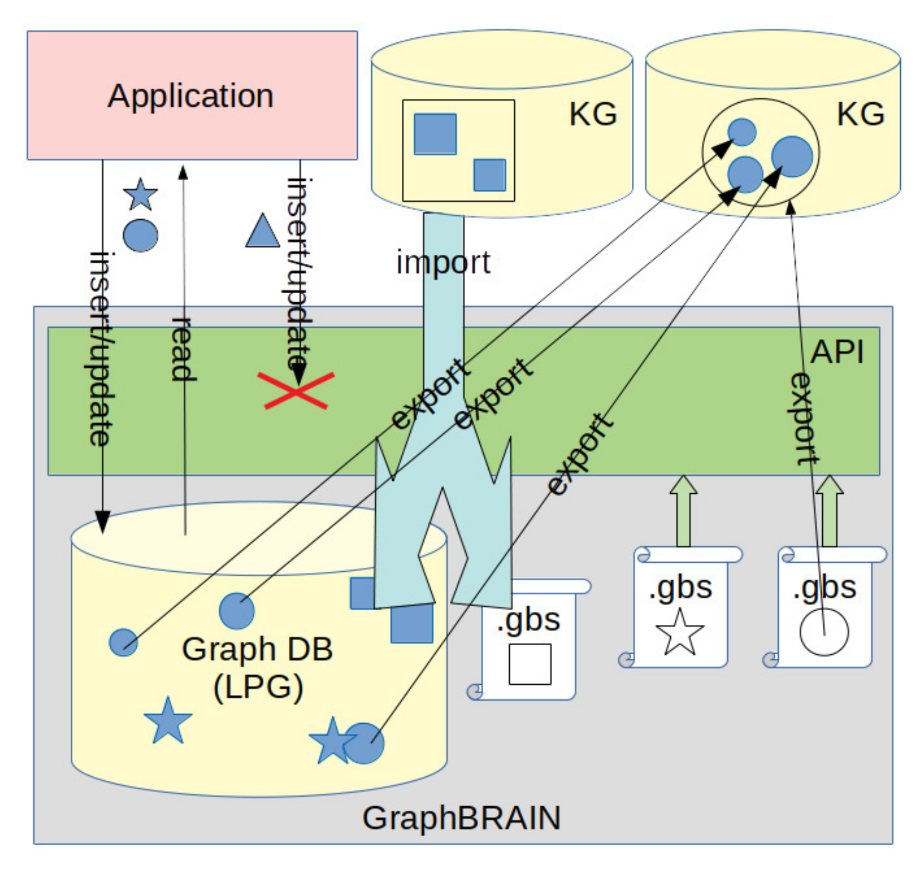
Instead, we propose an API, to be exploited by all applications accessing the DB, that wraps the DB and enforces compliance of the data with the intended schemas in both building and consulting the DB. In our vision KB designers must provide pre-specified data schemas, expressed in the form of ontologies for LPGs, that this API will interpret and use to drive all subsequent accesses to the DB. By referring to a schema, the applications will commit to be compliant with it, as in traditional databases. Just like in Triplestores and RDF* this will ensure a tight integration between the data and the schema. As opposed to Triplestores, RDF* and most of the cited works, where the ontology is ingested in the graph, the data/instances (stored in the graph DB) are kept apart from the schema/ontology (specified in a file external to the DB, using an ontological representation format). As discussed in
Section 4, we leverage this separation between the data repository and the data schema to obtain the additional opportunity of applying different (but compatible) schemas to the same DB. Indeed, each schema may represent a different, partial view on the same data, allowing to limit or expand the possible interactions depending on specific needs and adding flexibility to our solution. Again, this is not even thinkable in Triplestores.
Proposing an ontological format brings the need for tools to comfortably build, browse and edit the ontologies expressed in this format. Several tools have been proposed, in the literature and practice, for the current standard ontology representations (notably OWL). Each pursues different objectives as regards the construction, editing, annotation and merging of ontologies [
36]. Protégé [
37,
38], based on the OWLAPI, is the most popular and mature. Different versions, extensions and plugins for Protégé have been proposed (e.g., [
39,
40]), including an online version. Since sometimes they are not completely compatible with the original tool, we will take the OWLAPI as the standard reference in the rest of this paper. Since the ontological format for LPGs we propose in this paper has different features than those available for the RDF graph model, we also developed a corresponding tool for ontology definition and handling. In particular, it allows the ontology designer to specify attributes also for relationships and to specify labels for nodes and types for arcs, which is not allowed by extant ontological standards and tools. Therefore, our starting point was the need to define a schema for the graph DB, and the tool was developed so as to allow the users to comfortably define a schema to be used for building the KB. Then, in order to enable OWL reasoning capabilities, the translation in standard ontology format was a consequential objective. The various approaches proposed in the literature to assess the quality of tools for the construction of ontologies [
41] can provide useful hints for improving and extending our tool with advanced features.
3. GraphBRAIN Graph Database Scheme Format
The GraphBRAIN Schema (GBS) format we propose to define graph DB schemas consists of an XML file whose tags allow us to exploit the representational features provided for by the LPG model (we developed a DTD for automated syntax checking of GBS files). In the following, when specifying the GBS file structure, we will adopt the usual notation of square brackets to denote optional elements, curly brackets to denote repeated elements and pipes in parentheses to denote choices. Furthermore, we write XML tag names in boldface, XML tag attribute names in italics and entity or relationship names in smallcaps. Text in plain typeface reports comments useful to understand the various elements and their behavior.
The main structure of the XML with the tags and their nesting is reported in
Table 2, where the universal entity
Entity and the universal relationship
Relationship, acting resp. as the roots of the entity and relationship hierarchies, are implicitly assumed (remember that in ontological terminology entities correspond to classes and relationships correspond to object properties). Therefore, entities and relationships are to be specified only starting from the first level of specialization, which we will call
top-level. Since each node (resp., arc) in the graph must be associated with one top-level entity (resp., relationship), the top-level entities (resp., relationships) are to be considered as disjoint. They may be the roots of specialization hierarchies of sub-entities (resp., sub-relationships). The set of direct specializations of a (sub-)entity or (sub-)relationship are in turn disjoint and are not to be intended as a partition: instances that do not fit any of the specializations of a parent (sub-)entity or (sub-)relationship may be directly associated with the parent. Therefore, also the root and intermediate levels of each hierarchy admit instances in the knowledge base. This design choice prevents multiple inheritance (associating an instance to many classes belonging to different branches in the hierarchy). We partially recover this at the level of instances: when two instances of different (sub-)entities represent the same object, we link them using an
aliasOf relationship. The single reference object represented by all these instances takes the union of their attributes.
Entities and relationships are specified using the structure shown in
Table 3.
Reference is used only in relationships to specify their possible domain-range pairs,
taxonomy is optional (used only if the entity or relationship has sub-entities or sub-relationships) and allows us to conveniently represent the specialization-type assertions; all other object properties are to be specified in the
relationships section.
Attributes is mandatory for entities (an entity instance must be described by some attribute) and optional for relationships (a relationship may carry information in its very linking two instances).
Specialization is a recursive tag, allowing to define hierarchies of sub-entities or sub-relationships. In addition to its own attributes each specialization inherits all the attributes of the (sub-)entities (resp., (sub-)relationships) on the hierarchy path from its specific
specialization section up to the corresponding top-level entity (resp., relationship).
Some tags have XML attributes that specify the details of the item they represent in the schema:
domain tag:
name the unique identifier for the domain being described
author the author of the schema
version the version of the schema
entity tag:
name the unique identifier for the entity
relationship tag:
name the unique identifier for the relationship
inverse the unique identifier for the inverse relationship of name
reference tag:
subject the identifier of the entity that is the domain of the (sub-)relationship
object the identifier of the entity that is the range of the (sub-)relationship
specialization tag:
name the unique identifier for the specialization (sub-entity or sub-relationship)
[inverse] the unique identifier for the inverse sub-relationship of name (not used for sub-entities)
attribute tag:
name an identifier for the attribute
mandatory = ( true | false )
whether the attribute must take a value in each instance
distinguishing = ( true | false )
whether the attribute may concur in distinguish instances having the same values for mandatory attributes
display = ( true | false )
whether the attribute represents interesting additional information with respect to mandatory and distinguishing attributes, to be possibly displayed
datatype = ( integer |real|boolean|string|text|select|tree|date| entity )
[length] the maximum allowed number of characters (used only when datatype = string)
[target] an entity name (used only when datatype = entity)
Therefore, the union of mandatory and distinguishing attributes of an entity or relationship can be used to specify a key for uniquely identifying its instances. The union of mandatory, distinguishing and display attributes of an entity or relationship can be used to build and display a summary reporting the most relevant information about the instances.
Regarding datatypes, attributes of type integer, real, boolean, string, text take an atomic value of the corresponding type, where text is intended for free text of any length, differently from string which has a limited maximum length that can be specified in the ‘length’ attribute. Attributes of type date take values in one of the following forms:
Year;
Year/month;
Year/month/day.
where year is any integer, month
and day
. Attributes of type
select denote a choice in an enumeration of values, described using the substructure reported in
Table 4; attributes of type
tree denote a choice in a tree of values, described using the recursive substructure shown in
Table 5. Attributes of type
entity denote 1:1 relationships between an instance of the current entity and an instance of another entity (specified in the ‘target’ attribute of the tag), e.g., the birthplace of an entity Person would be modeled as an attribute of type
entity with target=‘Place’:
| <entity name="Person"> |
| <attributes> |
| <attribute name="birthplace" datatype="entity" target="Place"/> |
| </attributes> |
| </entity> |
As a conventional notation we propose identifiers made up of uppercase letters, lowercase letters or decimal digits only. They should start with an uppercase letter for entity names and enumeration or tree values, or with a lowercase letter for domain, relationship and attribute names. Multi-word names are built by juxtaposing their constituent words, using an uppercase letter for the first letter of each word (except for the first one, as prescribed above). When writing documentation, a relationship ‘rel’ between an entity ‘Subj’ and an entity ‘Obj’ can be represented using the dot notation
which is not ambiguous since dots are not allowed in our entity and relationship names.
Table 6 and
Table 7 show a fragment of a GBS file concerning the domain of computing. We see entity ‘Component’, representing an electronic component and including a taxonomy of sub-classes, some of which have specific attributes of various type, e.g., sub-class ‘Memory’ has attributes ‘capacity’ and ‘speed’ in addition to those inherited by ‘Component’ (‘name’, ‘description’, ‘originalPrice’ and ‘announcementDate’). In the relationships section we see that relationship ‘wasIn’ may be established between a ‘Component’ and an ‘Event’ (to signify that the component was on show at the event), or between a ‘Person’ and a ‘Place’ (meaning that the person was in that place), etc.
Each GBS schema is intended to describe one domain. However, sometimes wider domains involve ontological elements that are already described in more ‘basic’ schemas (e.g., the schemas for Cultural Heritage, Food and Transportations might be exploited in the ontology aimed at supporting a touristic application) and it might be useful to reuse such schemas, both for standardization of the definitions and for building on existing knowledge. Actually, the combination of many schemas is more powerful a representation than the simple juxtaposition of their elements. Indeed, their shared entities act as bridges that allow, through the relationships available in those domains, to connect proprietary entities of each domain that would not otherwise have a chance to be related with each other. In the GBS framework, classes and relationships in different ontologies are considered the same (and thus are shared) if they have the same name. They may have, however, different attributes, reflecting the different perspectives associated with the different domains. If an attribute is present in different domains it must have the same type in all of them. Moreover, additional cross-schema relationships (and entities) may be defined in the overall ontology, building on the existing ones. GBS schemas support such opportunity by providing for an optional section in which existing schemas can be imported. The structure of this section (delimited by tag
imports and placed at the beginning of the schema, before the entities and relationships) is as shown in
Table 8. The tag attributes are:
import tag:
schema: the name of a schema to be imported
delete tag:
elementtype = ( entity | relationship )
elementname: the name of the element to be deleted
Schemas are imported in the same order as specified by the sequence of import tags. Definitions of top-level elements (entities or relationships) in an imported schema having the same name as elements defined in previous imported schemas override the previous definitions. Finally, elements defined in the entities or relationships sections of the importing schema override elements with the same name in all imported schemas. Since it may happen that some elements of the imported schemas are not needed in the current domain, delete tags allow to remove them from the overall ontology.
In addition to the API for GBS-based handling of Neo4j, we developed tools for GBS schema/ontology editing and for data management. They were implemented as Web Applications based on the Java Server Faces technology and the PrimeFaces library. JavaScript was used for handling interactive browsing of the graph. A connection to Prolog allows it to carry out rule-based reasoning on selected portions of the data. Obviously Neo4j was used to store the knowledge graph, while Postgres was used to store user and usage data (roles, access rights, change log, etc.). A demo of the tools can be found at
http://193.204.187.73:8088/GraphBRAIN/ in the form of a general-purpose system for the collaborative development, management and (personalized) fruition of a KB, in the same spirit as Freebase [
42]. After logging into the system, the user may choose a domain and all subsequent interaction is driven by the corresponding GBS schema. Screenshots of the current online prototypes are shown in
Figure 1,
Figure 2 and
Figure 3.
Figure 1 shows the interface for building, editing and browsing GBS schemas/ontologies. In the left-hand-side section the entity hierarchy, with entity attributes and attribute types and values, can be handled. In the center section the same can be done for relationships, also including inverse relationships and references. On the right-hand-side section imports can be handled and existing schemas can be loaded. On the bottom several save and export buttons are available.
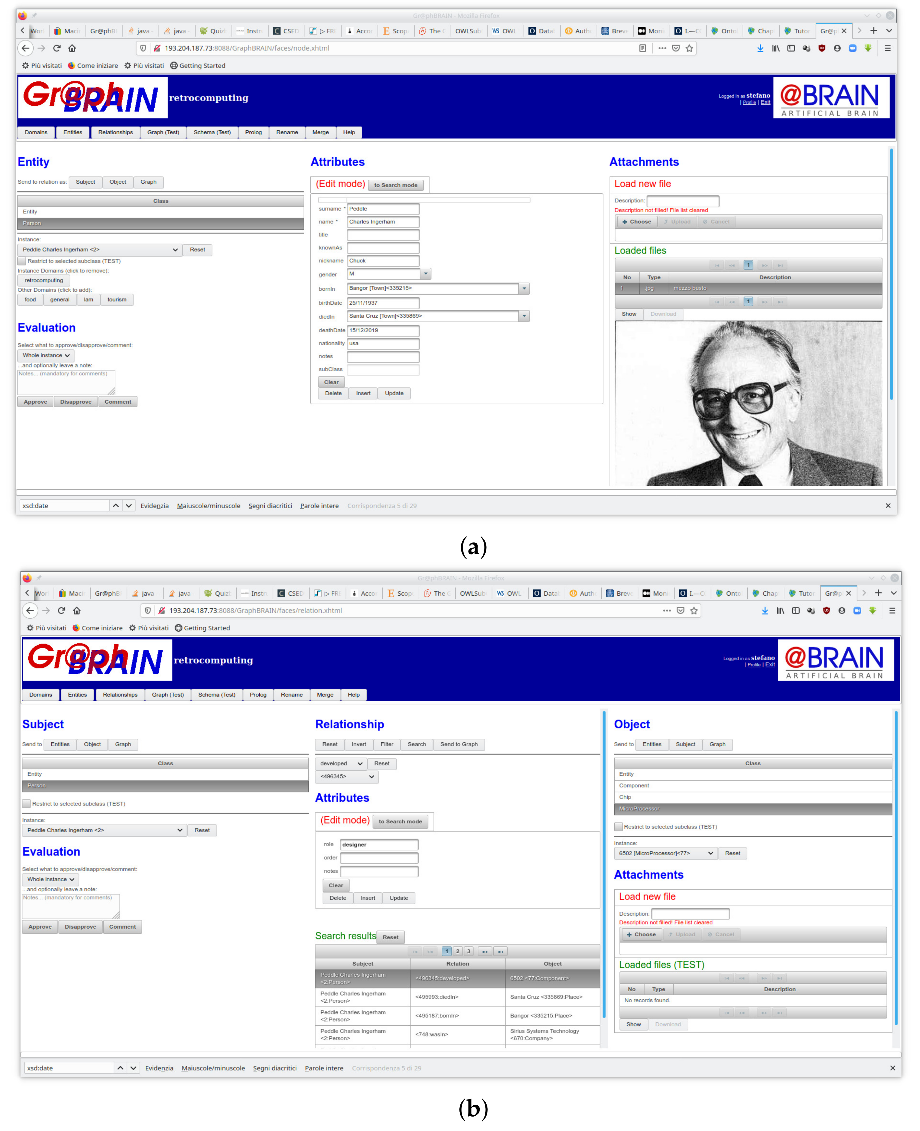
Figure 2 shows the interactive interface to feed and consult information in the knowledge base by direct interaction. It consists of two form-based tabs, one for entities (
Figure 2a) and one for relationships (
Figure 2b), allowing the user to insert, update, remove or query instances. The forms are automatically generated by the system from the GBS specification of a schema and interact with the graph DB using our API to enforce consistency with the selected schema. Let us first describe the entity tab. In the left-hand-side section (sub-)entities and corresponding instances can be selected. In the center section a form with the attributes of the selected (sub-)entity is shown, possibly filled with the values from the selected instance. Regarding the relationships tab, the center section allows to choose a relationship, for which subject and object (sub-)entities and corresponding instances can be selected in the left- and right-hand-side sections, respectively. When a triple (subject, relationship, object) is selected, the center section also shows a form with the attributes of the selected (sub-)relationship. If subject and object instances are also selected, a drop-down menu allows selecting a specific relationship instance, in which case the attribute form is filled with the corresponding values. More functions are available (e.g., handling of attachments to the selected instances, or search and collaborative evaluation facilities) but their description is beyond the scope of this paper.
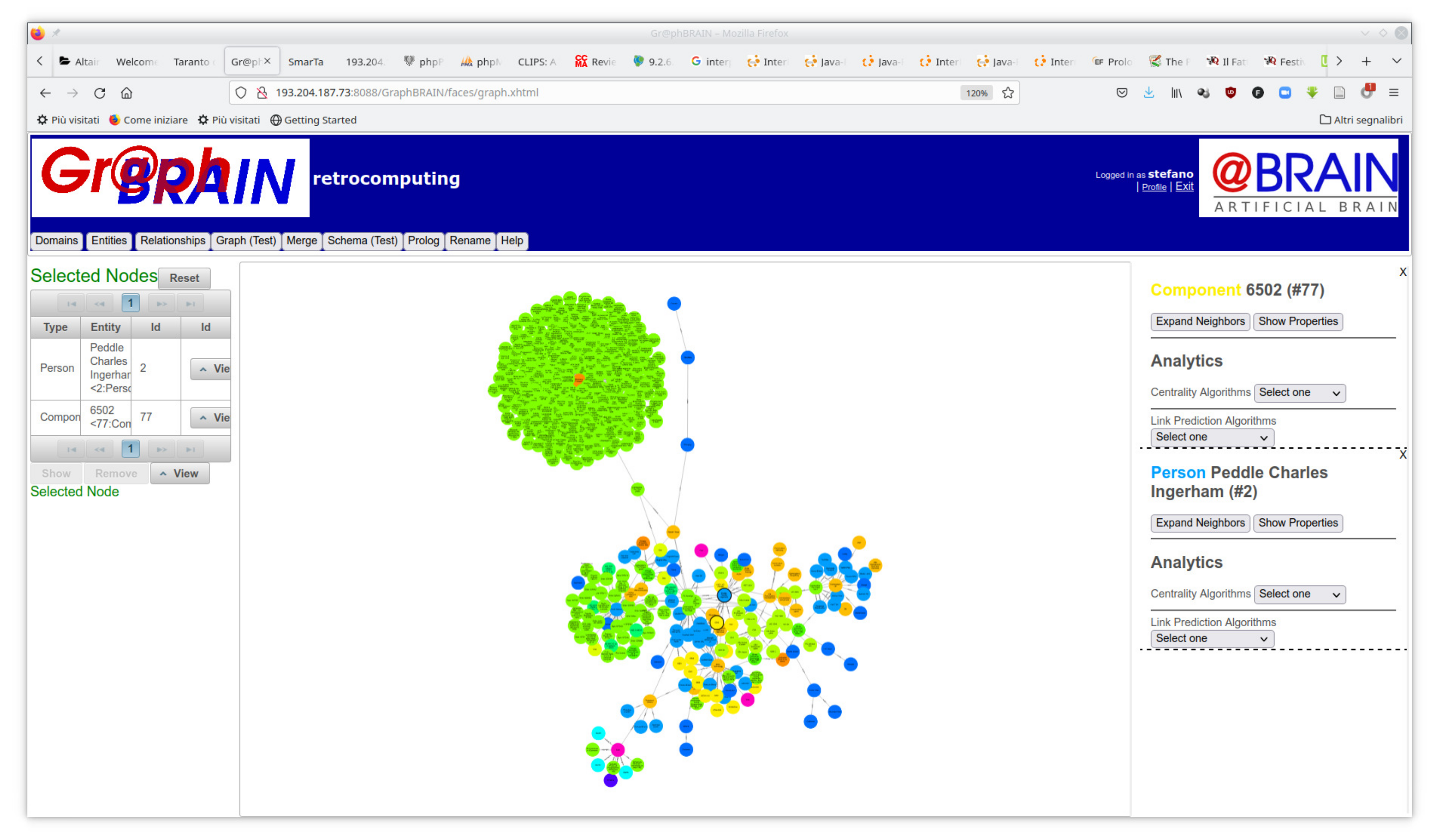
Figure 3 shows the tab in which users can display and manually browse the graph. Since the whole KB would be too large to be readable, only a portion thereof is shown in this tab. The portion is dynamically generated so as to focus on the portion of graph of interest to the user based on their profile, optionally starting from selected nodes specified by him. In the figure, the graph was generated for user ‘stefano’ starting from nodes representing Chuck Peddle (a pioneer in microprocessor design) and the 6502 (one of the earliest and most successful microprocessors on the market), identified by a thicker node border. Different colors of nodes denote different classes (e.g., light blue for Person, yellow for Component, etc.). At a glance, it is possible to see clusters of nodes that represent possibly relevant aggregates of information to be investigated or explored. Note that the nodes and arcs in this view may belong to different schemas, not only to the schema selected for the form-based interaction. Therefore, here the user may discover connections that are beyond the starting domain. The user may pan and zoom on the graph, drag nodes, dynamically follow links, read attributes of nodes and/or arcs, further expand the graph around nodes of interest and run analytics and mining algorithms from menus on the right-hand-side and contextual menus that appear by clicking on the graph. The information on a node or arc in this view is the complete set of properties for that node or arc, gathered from all domains in which it is involved.
5. Conclusions
Formal ontologies, described as RDF graphs, have traditionally been investigated as a means to formalize an application domain so as to carry out automated reasoning on it. The union of the terminological and assertional parts of an ontology is known as a Knowledge Graph. On the other hand, database technology has ever since focused on the optimal organization of data so as to boost efficiency in their storage, management and retrieval. Graph databases, based on the Labeled Property Graphs (LPG) model, are a recent technology specifically focusing on element-driven data browsing rather than on batch processing. Furthermore, graph databases are typically schema-less, preventing uniform interpretation of the data by, and interoperability of, the applications. In spite of the patent and intuitive complementarity and connections between these technologies, the underlying graph models are partially incompatible and little exists to bring them to full integration and cooperation.
Whilst most efforts in the literature are OWL-centric and aimed at mapping RDF ontologies to LPGs, we place more emphasis on the database, so as to benefit from efficient data handling, and aim at enriching it with reasoning capabilites that exploit as much as possible the flexibility of the LPG model. To the best of our knowledge this is a completely novel perspective in the literature.
For this purpose, we proposed to express database schemas in the form of ontologies, so as to clearly describe the database content and to allow users to carry out complex reasoning on it, beyond the queries allowed by the database query language. Specifically, we defined an intermediate format (GBS) that can be easily mapped onto formal ontology standards on one hand and onto the graph database structure on the other. A peculiarity of our approach is that many schemas/ontologies can be applied to the same graph to express different domains or perspectives on its content. These ontologies may share classes and relationships, allowing cross-fertilization of the knowledge from the corresponding domains. The use of ontologies enables multistrategy formal, automated reasoning on the data, that goes much beyond what simple queries can do.
In this paper, for the first time, we provided the full specification for GBS and discussed how its components can be mapped on a most famous graph DB (Neo4j) and on a standard formal ontology (OWL). Operationally, this framework is supported by an API that is meant to act as a wrapper for the DB, ensuring that its content is compliant with a GBS schema, and that can connect the instances in the DB with an ontological reasoner using the same schema as an ontology. Based on this API many different applications may exploit this powerful combinations of databases and ontologies in their functions. Among these applications we developed a tool to build, browse and edit GBS schemas, and a tool to add, edit and consult the DB content according to a pre-specified schema. Such a tool is described in this paper, as well.
The API and tools are continuously under development to be extended and refined, and research is ongoing to further improve the mapping between the GBS and OWL formalisms, so as to fully exploit their respective advantages in both the instance (database) and the schema (ontology) part of the knowledge graph. In particular, we are working at the extension of the schema format with additional tags/features to express information that may improve the effectiveness of reasoning at the ontological level.


