Abstract
Low-voltage and high-current direct current (DC) power supplies are essential for aerospace and shipping. However, its robustness and dynamic response need to be optimized further on some special occasions. In this paper, a novel rectification system platform is built with the low-voltage and high-current permanent magnet synchronous generator (PMSG), in which the DC voltage double closed-loop control system is constructed with the backstepping control method and the sliding mode variable structure (SMVS). In the active component control structure of this system, reasonable virtual control variables are set to obtain the overall structural control variable which satisfied the stability requirements of Lyapunov stability theory. Thus, the fast-tracking and the global adjustment of the system are realized and the robustness is improved. Since the reactive component control structure is simple and no subsystem has to be constructed, the SMVS is used to stabilize the system power factor. By building a simulation model and experimental platform of the 5 V/300 A rectification module based on the PMSG, it is verified that the power factor of the system can reach about 98.5%. When the load mutation occurs, the DC output achieves stability again within 0.02 s, and the system fluctuation rate does not exceed 2%.
1. Introduction
In the fields of shipping, electrolysis, and electroplating, direct current (DC) power supply is required to operate in low-voltage and high-current modes. For example, in the all-electric propulsion system, the generator has an obligation to have lower voltage and higher power output characteristics due to the limitation of output voltage. However, the process of commutating the rectification current leads to the distortion of the alternating current (AC) voltage waveform, which leads to harmonic loss. Therefore, realizing the high performance and high-power DC power supply system is a problem that has received considerable attention in recent years. Since the setting of the proportional-integral (PI) parameters in conventional PI control is sensitive to the rectification itself and includes the hysteresis of the PI control itself, it is difficult to maintain excellent dynamic performance and robustness in four-quadrant operation. Meanwhile, due to the time-varying of the switching power supply system, the control method needs to be optimized to keep the output of the converter in a stable state. The application of the modern nonlinear control method has become one of the research hotspots in power electronic control [1,2]. Commonly, there are internal model control, direct power control, passive theoretical control, and exact feedback linearization control. The purpose of control is to maintain the DC output voltage at the expected value [3]. Direct power control method indirectly controls the output voltage by directly controlling the active and reactive power. In [4], a method for direct power control using natural switching surfaces was proposed, which considered the output voltage when selecting the switching state. Thus, the control method does not prescribe an external voltage control loop and can greatly improve the dynamic performance of the DC output voltage [5,6]. However, due to the limitation of the current circuit, harmonic distortion is easily generated in the input current, which reduces the power factor. Passive theoretical control is realized through state feedback and changing the energy function of the system. Its construction is to create Lyapunov equivalence expressions for the research object of a nonlinear system, from which a set of static state or output feedback is found to satisfy passive expressions. The process of establishing Lyapunov’s expressions is the process of passivating the object of study [7]. Adopting passive control to control the pulse width modulation voltage source rectification system improves the dynamic and steady-state characteristics and disturbance of the system. The exact feedback linearization method obtains the exact feedback linearization model by transforming the model with coordinate and state feedback expressions, which can accurately reflect the system model. The method can make the DC output voltage response of the system faster and has reliable tracking performance. However, the method is based on the exact elimination of nonlinearity. Because the parameters can vary, this technique is not effective [8]. As well as the linearization process is complex and difficult to find the optimal feedback control rule [9]. Internal model control is a control strategy based on a mathematical model of the process for controller design. It has the simple structure [10], the intuitive design, and does not require an accurate object model, has limited online adjustment parameters, but poor robustness.
The backstepping control method is a recursive and nonlinear control method [11] that has been implemented in Buck circuits, inverter circuits, and PMSM [12,13,14]. The backstepping control method decomposes the system into subsystems that do not exceed the order of the system. Then intermediate virtual control variables and Lyapunov functions are designed for each subsystem. Finally, the control function that satisfies Lyapunov’s stability theory is given [11]. So far, the design of the entire control system is completed. The backstepping control method allows global adjustment and accurate tracking of the system. Thus, making the performance metrics of the system reach the expected values. Derivatives of virtual control are required at each step of the design process [15] to the later subsystems through virtual compensation, which enables stable control of preceding subsystems. Therefore, the construction of the reasonable virtual control variable is the most important step in the design of the backstepping control method. In [16], a new nonlinear and adaptive state feedback controller with a fast-adaptive robust differentiator was presented, which avoids the complexity of the existing backstepping method but its velocity of tracking input error is slow. In [17], a robust integral backstepping controller is designed to reduce overshoot/undershoot and steady-state error, but its response time is long and the design process is complex. In [18], the study focuses on the design of global backstepping control for direct power control. This three-phase pulse width modulation (PWM) rectifier has control performance, including lower total harmonic distortion value, less harmonic orders, and faster dynamic response speed. However, no conclusion is given about the high power factor operation of the system after load mutation. Although many previous works have been proposed to control nonlinear systems, none can improve the robustness of the system while rapidly tracking input errors under high-power output conditions. Compared with other papers, the novelties and advantages in our work can be summarized as follows:
- (1)
- The asymptotically stable nonlinear controller is designed using the backstepping control method for the single-input single-output (SISO) model of the active component control structure. The reactive component control structure is uncomplicated and it does not reflect the advantages of the backstepping control method, so this paper uses the sliding mode variable structure (SMVS) to improve it.
- (2)
- The rectification system can realize low-voltage and high-current DC power generation and high-power output;
- (3)
- The rectification system achieves better dynamic and static performance, improves responsiveness and robustness, and maintains the high power factor operation after load mutation.
The main structure of this paper is as follows, and the second part introduces the controller design combining the backstepping control method and the SMVS. The third part describes the circuit simulation design of the system based on Simulink. Experimental results are provided in the fourth part, and the fifth part concludes the paper.
2. Methods
Figure 1 shows the outline of the double closed-loop control system. The control system is composed of the active component control structure controlled by the backstepping control method and the reactive component control structure controlled by SMVS.
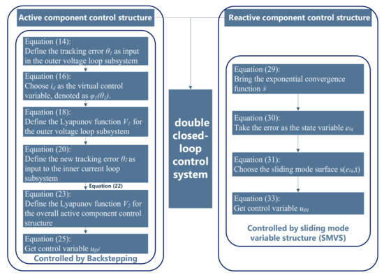
Figure 1.
Outline of double closed-loop control system.
2.1. Active Component Control Structure
The mathematical model of voltage and current under the a-b-c three-phase stationary axis is converted to the d-q dynamic axis, and the mathematical model of the three-phase rectification system under the d-q axis can be obtained as [19]
where id and iq are the active and reactive current components of the AC input current in the d-q coordinate system; ed and eq are the active and reactive voltage components of the AC input voltage in the d-q dynamic system; Sd and Sq are voltage modulation ratios on d and q axis; ugd and ugq are the voltage modulation control variables on d and q axis; udc is the DC output voltage; idc is the DC output current; iL is the load current; RL is the load; ω is the angular velocity of AC current; L is the equivalent inductor in the three-phase permanent magnet synchronous generator (PMSG); R is the equivalent resistance in the three-phase PMSG; C is the DC energy storage capacitance.
This paper adopts the quasi-linearization processing used in [19], which is defined as
When using the equivalent coordinate transformation, the AC and DC sides keep the input and output power conserved. The AC side active power and DC side power can be expressed as
Multiplying both ends of Equation (2) by udc and put them into Equation (4). Then the improved quasi-linearized model can be derived by
The improved Equation (6) is formally a linear system, but considering the variables substitution described above, Equation (2) is still essentially a nonlinear system. Therefore Equation (6) is known as a quasilinear model [20]. The variables substitution is formally linearized and does not change the nature of the system as a nonlinear system. The purpose of using variables substitution here is intended to facilitate the subsequent design of the controller.
When the three-phase AC input voltage is symmetrical and the d-axis of the d-q dynamic system coincides with the three-phase AC input voltage vector, it follows that
where Em is the amplitude of AC input voltage.
After bringing Equations (4) and (7) into Equations (1) and (6), the SISO system with the active component structure can be represented by
In this paper, the backstepping control method is used to control the active component control structure, which is to achieve the goal of maintaining the stable DC output voltage and to ensure that the rectification system can operate normally.
The backstepping control method is built with a subsystem and radiates out another subsystem. Because of this recursive structure, it is possible to start the design process on a known stable system and ‘step back’, outputting a new controller and gradually stabilizing each external subsystem. The process terminates when the final external control is reached after several steps. Therefore, this process is known as backstepping control [21].
The mathematical model of a SISO nonlinear system is
where is the state variables of the system, which can be considered as the virtual control variable of the subsystem; is the uncertainty of the system; is a smooth function and , and the control objective is to drive the state variables toward its expected value . The design concept of the backstepping control method is to take as the virtual control variables, then construct a Lyapunov function Vi and design a virtual feedback control so that the error has asymptotic characteristics. The backstepping control method ensures the convergence of the error to zero [22]. Finally, construct a Lyapunov function and control variable for the whole system so as to achieve asymptotic stability of the whole system [20].
In this paper, the control structure is divided into two parts. The first part is the outer voltage loop subsystem and the second part is the inner current loop subsystem. The output id of this subsystem can be obtained by using the squared error between the actual DC output voltage value and the expected DC output voltage value as the input of the outer voltage loop subsystem. Then the id is set as a virtual control variable, and the second part of the subsystem can be designed by tracking the error between id and the d-axis component of the AC input current, which is the input into the inner current loop subsystem. After that, the control function of the active component control structure is obtained by satisfying the Lyapunov stability theory.
Convert the SISO system of active component structure into the mathematical model of the backstepping control method, namely, transform Equation (8) into the form of Equation (9). If [x1 x2] = [u2dc id]T is set, we can obtain the following:
The step of applying the backstepping control method to design the active component control structure is as follows:
Step 01: Define the tracking error as input in the outer voltage loop subsystem, in which udcref is the expected value of the DC output voltage.
The derivative of θ1 is
Step 02: Since id is not the control input, in the backstepping design, id is called the virtual control variable, denoted as φ1(θ1). PI control is used to eliminate the static deviations of the input of the outer voltage loop subsystem [20], so that φ1(θ1) is expressed as
where k1 is the proportional gain, k2 is the integral gain.
Bringing Equation (16) into Equation (15), the following is given:
Step 03: Define the Lyapunov function V1 and its derivative for the outer voltage loop subsystem of
Step 04: Define the new tracking error as input to the inner current loop subsystem.
The derivative of θ2 is
Let , then get
Select control variable:
Bringing Equation (23) into Equation (21), we can obtain
Step 05: Define the Lyapunov function V2 and its derivative for the overall active component control structure
From Equation (26), the reaching condition can be derived by
Then the derivative of the Lyapunov function V2 is negative definite and the active component control structure is global asymptotic stability.
2.2. Reactive Component Control Structure
The control objective of the reactive component control structure is to enable the AC input current to quickly track the voltage and to present a nearly complete smooth sine wave so that the power factor of the rectification system can reach 1.
The iq is selected as the input of the reactive component control structure to control the power factor, and the SISO system of the reactive component structure is obtained
The reactive component control structure is controlled using the SMVS which is a nonlinear control method that switches from one continuous structure to another according to the current position in the state space. Therefore, SMVS is a variable structure control method that will slide along the boundary of the control structure. The motion of the system as it slides along these boundaries is referred to as the sliding mode, and the geometric trajectory formed by these boundaries is called the sliding surface [23].
An exponential convergence function is utilized to design the control variables of the reactive component control structure. The main advantage is that the process of approaching the sliding mode surface converges with the changed velocity. It starts with the fast velocity and then gradually decreases, and the velocity is close to zero when the sliding mode surface is about to be reached. This not only shortens the convergence time, but also narrows the velocity of the motion point when it reaches the switching surface. The chatter is weakened while the dynamic characteristics of the control structure are improved.
Here, an exponential convergence function is used, making
where , is the exponential convergence term, which solution is ; is the isokinetic convergence term.
In which
The exponential convergence term in Equation (29) can only guarantee that the motion point approaches the switching surface infinitely, and does not guarantee that it can be reached in finite time. Thus, it is an important condition for the control of the SMVS that the motion point can reach the switching surface in finite time. Therefore, it is necessary to add the isokinetic convergence term to ensure that the convergence velocity tends to be zero, so that the condition of reaching in finite time can be satisfied. To satisfy the relevant performance indicators of the control structure and play a fast convergence while weakening the chattering effect, the two parameters of the exponential convergence term should be as large as possible while the value should be as small as possible.
Taking the error between the expected value and the actual value as the new state variable, Equation (28) can be rewritten as
where .
The purpose of the control is to obtain the unit power factor, which is to control iq to 0. Following Equation (30) and the theory of SMVS, it can be inferred that the choice of sliding mode surface can ensure the robustness of the closed-loop system, which can be defined as
From Equation (31), it follows that
Therefore, by combining Equations (28), (31), and (32), the control variable of reactive component structure can be calculated as
Once ugq is obtained, the pulse can be generated with the space vector pulse width modulation.
The purpose of the control variable of reactive component structure is to ensure that the structure state can reach the switching surface quickly and remain near the sliding surface. To avoid a series of problems such as discretization of continuous variables, the ugq is converted to a voltage signal in the a-b-c stationary axis as the input signal, and the control pulses of the metallic oxide semiconductor field effect transistors (MOSFETs) in the three-phase rectification bridge are obtained directly by the modulation with fixed switching frequency.
3. Results
For the convenience of the study, a single three-phase rectification module is selected which consists of the three-phase AC input voltage section, the rectification and filtering section, the phase locked loop section, and the double closed-loop control section. Figure 2 shows the simulation model of DC voltage control system, in which the reactive component control structure of the double closed-loop control system will be analyzed by using the backstepping control method and the SMVS, respectively. Table 1 shows the simulation parameters of the three-phase rectification module.
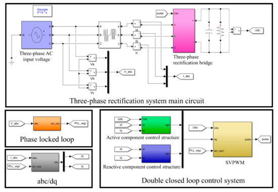
Figure 2.
Simulation model of DC voltage control system.

Table 1.
Simulation circuit parameters.
3.1. Active Component Control Structure
Figure 3 shows the simulation model of the active component control structure. The input of the outer voltage loop subsystem is the squared error between the actual voltage value and the expected voltage value on the DC side. The id is selected as the virtual control variable to construct the state expression of the outer voltage loop subsystem, and the stability of the subsystem is judged by the Lyapunov stability theory, then the reasonable expression can be obtained. According to the definition of the backstepping control method, it is known that the virtual control variable constructed by the outer voltage loop subsystem is used to control the inner current loop subsystem. The φ1(θ1) module is constructed in the outer voltage loop subsystem so that the error between φ1(θ1) and virtual control variable of the outer voltage loop is used as the input of the inner current loop subsystem. The δ2 module is constructed to derive the ugd, which is the output of the active component control structure, and the output satisfies Lyapunov stability theory.
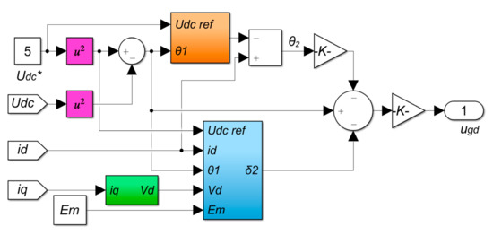
Figure 3.
Simulation model of active component control structure controlled by backstepping control method.
3.2. Reactive Component Control Structure
Figure 4 shows the simulation model of the reactive component control structure using SMVS. The reactive component control structure is employed to make the input current fast track the voltage. Thus, the iq, which is the current of the input reactive component axis, is selected and its expected value is set to zero to achieve the objective of controlling the reactive power nearly to zero. Thence, the error between iq and its expected value is used as input to obtain the ugq that is the output of the reactive component control structure.
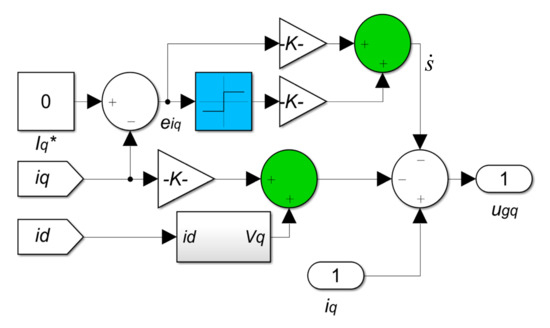
Figure 4.
Simulation model of reactive component control structure controlled by SMVS.
3.3. Phase Locked Loop
In the phase locked loop of three-phase rectification system as shown in Figure 5, the voltage of q axis is controlled to be equal to 0, which is combined with the feedback output voltage to generate an error voltage [24], and then PI control is used to adjust the voltage without static error. The output of the PI controller is superimposed with the actual input rated frequency to obtain the output frequency, and in turn, the angle and sine values can be obtained.
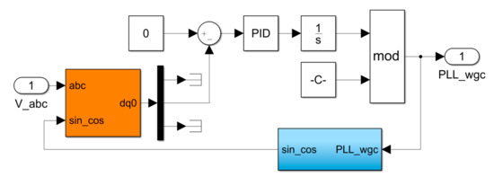
Figure 5.
Simulation model of phase locked loop.
3.4. Simulation Waveform Comparison and Analysis
3.4.1. Startup Characteristics
Figure 6 exhibits the startup response of DC output voltage and current in the rectification system at steady state. It can be observed that the rectification system starts at 0 s and quickly enters the steady state without overshoot. At the time of 0.07 s, the DC output voltage reaches a stable value of 5 V, and the DC voltage starts with excellent response characteristics. The simulation results indicate that the double closed-loop control system operates stably and achieves the expected object.
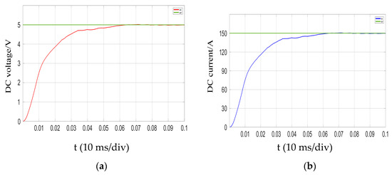
Figure 6.
Startup response of DC output: (a) voltage waveform; (b) current waveform.
3.4.2. Load Mutation
The load mutation is that the load increases and decreases suddenly at 0.5 s. Figure 7 demonstrates the waveform of DC output voltage and current when the load suddenly decreases from 32 Ω to 16 Ω at 0.5 s, respectively. The analysis demonstrates that after the load decreasing, the voltage value returns to stability after reaching about 4.9 V. Meanwhile, the current stabilizes at 300 A, and the whole response process lasts for 15 ms.
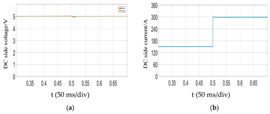
Figure 7.
Simulated waveform of DC output when the load suddenly decreases: (a) DC output voltage waveform; (b) DC output current waveform.
Figure 8 shows the waveform of DC output voltage and current when the load suddenly increases. It can be noticed that the DC voltage value starts to approach the steady state value after reaching about 5.1 V, and the current is stable at 75 A. The time of the entire response process is about 16 ms.
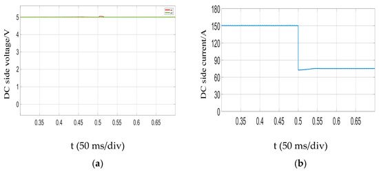
Figure 8.
DC output voltage and current waveform when the load suddenly increases: (a) DC output voltage waveform; (b) DC output current waveform.
3.4.3. Comparative Simulation Analysis
The recursive structure of backstepping control method is to start the design process with a known stable system and ‘back’ to a new structure for the output, which is to gradually stabilize each external subsystem. However, for the reactive component control structure, there is only a single structure without a gradual stabilization process, so the SMVS is used for its control. The SMVS has been verified to be an efficient and pretty popular robust control technique since it owns some well-known and strong properties in disturbance rejection and insensitivity to model uncertainties and parameter variations occurring in dynamical systems [25,26] which can regulate reactive power and reduce harmonic distortion to reach better system requirements. Therefore, for comparison during load mutation, the simulation is concentrated on the reactive component control structure with backstepping control method and SMVS, respectively.
To verify the performance difference between SMVS and backstepping control method, the simulation models of the reactive component control structure using these two kinds of control methods respectively are presented in Figure 9.
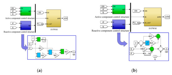
Figure 9.
Simulation model of reactive component control structure: (a) controlled by backstepping control method; (b) controlled by SMVS.
Figure 10 shows the Fast Fourier Transform comparison between backstepping control method and SMVS. As a standard sine wave power supply, the synchronous generator contains only odd harmonics. However, the non-linearity of PWM rectifier components, the dead zone of the control signal and the lag of the phase-locked loop all lead to the existence of even harmonics, but they are still far lower than the odd harmonics. For the reactive component control structure controlled by backstepping control method, as shown in Figure 10a, the fundamental voltage is 5 V and the total harmonic distortion of voltage is 0.45%; for the reactive component control structure controlled by SMVS, as shown in Figure 10b, the fundamental voltage is 5 V and the total harmonic distortion of voltage is 0.13%. It is generated that the SMVS is better than the backstepping control method for voltage harmonic suppression.
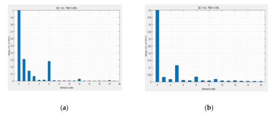
Figure 10.
Fast Fourier Transform analysis of reactive component control structures: (a) controlled by backstepping control method; (b) controlled by SMVS.
Figure 11 displays the comparison of A-phase input current between backstepping control method and SMVS after halving the load. The analysis demonstrates that the AC input current value quickly doubles to the stable value of 360 A. From Figure 11a, it can be noticed that A-phase input current which is controlled by the backstepping control method has the large overshoot during the two cycles of AC input current, and over after two cycles, the A-phase current reaches the stable value with the response time of 0.04 s. After the load mutation, the state point of the system deviates from the switching surface, but under the control of the SMVS, the state point tends to move towards the switching surface. From Figure 11b, it can be seen that the AC input current soon returns to the new steady state value of 360 A. The current overshoot is obviously reduced, and the whole process time of adjustment is within 0.03 s.
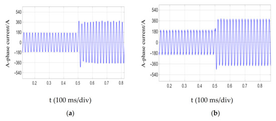
Figure 11.
A-phase current waveform when the load suddenly decreases: (a) Controlled by backstepping control method; (b) Controlled by SMVS.
Figure 12 displays the analytical comparison of AC input power factor between backstepping control method and SMVS after halving the load. The AC input current has a fast response, so it has the good tracking effect on the input voltage. Analysis shows that compared with the backstepping control method, the SMVS control the reactive component control structure can accelerate the responsiveness of the AC input current and enter a new steady state faster after load mutation. Furthermore, the power factor reaches stability in 30 ms.
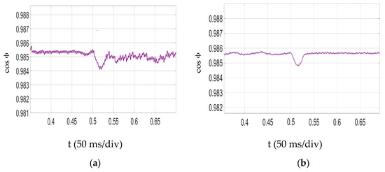
Figure 12.
Power factor on the AC input side when the load suddenly decreases: (a) Controlled by backstepping control method; (b) Controlled by SMVS.
Figure 13 shows the comparison of A-phase input current between backstepping control method and SMVS when the load suddenly increases from 32 Ω to 64 Ω. The analysis shows that the value of AC input current soon reaches a stable value of 90 A. From Figure 13a, it can be seen that the reactive component control structure controlled by the backstepping control method has the response time of 0.04 s and reach a steady state value after two cycles of AC input current; for the reactive component control structure controlled by the SMVS, as shown in Figure 13b, the AC input current reaches a new steady state value of 90 A within 0.03 s.
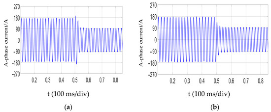
Figure 13.
A-phase current waveform when the load suddenly increases: (a) Controlled by backstepping control method; (b) Controlled by SMVS.
Figure 14 shows the analytical comparison of AC input power factor between backstepping control method and SMVS when the load suddenly increases from 32 Ω to 64 Ω. Compared to the backstepping control method, the SMVS makes the reactive component control structure enter the new steady state faster after the load mutation and the power factor reaches stability in 30 ms.
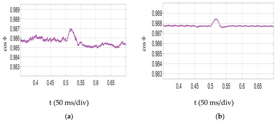
Figure 14.
Power factor of AC input side when the load suddenly increases: (a) controlled by backstepping control method; (b) controlled by SMVS.
According to the above simulation results, the active component control structure controlled by the backstepping control method can enhance the robustness of DC output voltage, and the squared error between the value of DC output voltage and the predicted value of DC output voltage makes the DC output voltage respond quickly. Meanwhile, the reactive component control structure controlled by the SMVS can effectively enhance the robustness of the system, which has low current distortion. It can be observed that compared with the global backstepping control method, the rectification system with the combination of backstepping control method and SMVS has better performance. The DC output voltage is more stable, the current distortion is smaller, and the AC input current track AC input voltage faster in real time. Under the load mutation, both DC output voltage and AC input current can reach the steady state quickly.
3.5. Verification of the Experimental Result
According to the experimental principles, an experimental test platform for low-voltage and high-current DC power generation system with double closed-loop control based on DSP28335 was built to verify the effectiveness of backstepping control method and SMVS, as shown in Figure 15. The platform can directly output DC power to supply the load after the three-phase PMSG generates AC power and rectifies it by the confluence plate. The confluence plate is composed of upper and lower legs of the bridge and in order to improve the conduction capability, each leg is connected in parallel with five MOSFETs which are fixed on the heat sink. The experiments of load mutation are carried out on the experimental platform, on which the phase voltage on the AC side of the three-phase PMSG is 3.8 V and the output voltage on the DC side is 5 V. The overall structure of the rectification double closed-loop control system consisting of active and reactive component control structure is shown in Figure 13.
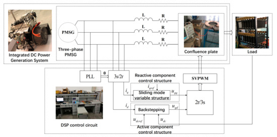
Figure 15.
Low-voltage and high-current DC voltage control system.
The DC output voltage of the rectification system is shown in Figure 16. From the figure, it can be seen that the output waveform is smooth, with the voltage value of 5 V and the current value of 150 A, which is consistent with the DC characteristics. The experimental results are basically consistent with the dynamic simulation results and satisfy the DC output requirements.
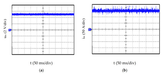
Figure 16.
DC output waveform: (a) voltage waveform; (b) current waveform.
The experimental waveform is shown in Figure 17 which shows the DC output voltage and current waveform when the load suddenly increases and decreases, respectively. Owing to the presence of internal resistance, the external characteristics of the rectification system change when the load changes under the condition of the same duty cycle. The DC output voltage in both Figure 17a,c were able to quickly return to a stable state with a brief fluctuation and the DC output voltage remains at 5 V. Meanwhile, the DC output current in Figure 17b is able to quickly reach 300 A in 20 ms; the DC output current in Figure 17d is also able to reach 75 A in 30 ms, returning to a new steady state. The experimental results are basically consistent with the dynamic simulation results, which prove that the dynamic control performance of the system is better after the combination of backstepping control method and SMVS.
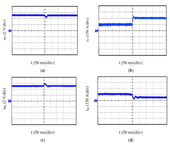
Figure 17.
DC output voltage and current waveform: (a) voltage waveform when load decreases; (b) current waveform when load decreases; (c) voltage waveform when load increases; (d) current waveform when load increases.
The waveform of A-phase input current is shown in Figure 18 when the load suddenly increases and decreases under the combination of backstepping control method and SMVS. It can be observed that A-phase input current rises and falls more smoothly without overshoot and reaches stability after 30 ms. The experimental results are basically consistent with the dynamic simulation results.
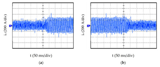
Figure 18.
A-phase current waveform when load changes: (a) load decreases; (b) load increases.
4. Conclusions
In this study, a rectification control system by using of backstepping control method and SMVS in a multi-three-phase PMSG is proposed with the aim of stabilizing the DC output at low-voltage and high-current. In the active component control structure, the backstepping control method is used for optimization, which can achieve fast tracking and global adjustment of the system by setting intermediate virtual control variables and satisfy the stability requirement of Lyapunov stability theory so that a reasonable control variable is finally designed. The reactive component control is stabilized by the SMVS to stabilize the power factor. In this paper, the performance of the reactive component control structure is compared by using two methods, the backstepping control method and the SMVS. The simulation results demonstrate that the system robustness is better and the dynamic performance is greatly improved when the SMVS is applied to the reactive component control structure in the rectification control system. The backstepping control method and the SMVS constitute the double closed-loop control system, whose stability is not easily disturbed by large signals, and the power factor can quickly reach a steady state. The experimental results are consistent with the simulation results which prove that the control strategy combining the backstepping control method and the SMVS is an effective and reliable control scheme. This study is only a preliminary discussion of the design and performance of the three-phase voltage rectification double closed-loop control system. Furthermore, study the situation of the rectification system with nonlinear load, and make it design together with the whole system of the post-nonlinear load, optimize the matching, and get the best performance and reliability.
Author Contributions
Conceptualization, J.L. and X.Q.; Methodology, J.L. and X.Q.; Software, X.Q.; Validation, J.L. and X.Q.; Formal analysis, J.L. and X.Q.; Investigation, J.L.; Writing—original draft preparation, J.L. and X.Q.; Writing—review and editing, J.L. and X.Q.; Visualization, H.H.-C.I.; Supervision, H.H.-C.I.; Funding acquisition: J.L. All authors have read and agreed to the published version of the manuscript.
Funding
This research was funded by Natural Science Foundation of Heilongjiang Province, grant number LH2019E067.
Conflicts of Interest
The authors declare no conflict of interest.
References
- Zhang, P.H.; Yang, G.J.; Li, T.C. Direct voltage control of three phase PWM rectifier based on feedback linearization. Proc. CSEE 2010, 30, 39–46. [Google Scholar]
- Gensior, A.; Sira-Ramirez, H.; Rudolph, J.; Guldner, H. On Some Nonlinear Current Controllers for Three-Phase Boost Rectifiers. IEEE Trans. Ind. Electron. 2009, 56, 360–370. [Google Scholar] [CrossRef]
- Eltoum, M.M.; Al-Mahzamah, F.; El Ferik, S. Feedback Linearization Sliding Mode Control of Three-Phase Grid-tied AC/DC PWM Converter. In Proceedings of the 2020 17th International Multi-Conference on Systems, Signals & Devices (SSD), Monastir, Tunisia, 20–23 July 2020; pp. 1116–1121. [Google Scholar]
- Bouafia, A.; Krim, F.; Gaubert, J.-P. Fuzzy-Logic-Based Switching State Selection for Direct Power Control of Three-Phase PWM Rectifier. IEEE Trans. Ind. Electron. 2009, 56, 1984–1992. [Google Scholar] [CrossRef]
- Ge, J.; Zhao, Z.; Yuan, L.; Lu, T.; He, F. Direct Power Control Based on Natural Switching Surface for Three-Phase PWM Rectifiers. IEEE Trans. Power Electron. 2015, 30, 2918–2922. [Google Scholar] [CrossRef]
- Malinowski, M.; Kazmierkowski, M.P.; Hansen, S.; Blaabjerg, F.; Marques, G. Virtual flux based direct power control of three-phase PWM rectifiers. In Proceedings of the Thirty-Fifth IAS Annual Meeting and World Conference on Industrial Applications of Electrical Energy, Rome, Italy, 8–12 October 2000; pp. 2369–2375. [Google Scholar]
- Wan, C.; Huang, M.; Tse, C.K.; Wong, S.C.; Ruan, X. Nonlinear Behavior and Instability in a Three-Phase Boost Rectifier Connected to a Nonideal Power Grid with an Interacting Load. IEEE Trans. Power Electron. 2012, 28, 3255–3265. [Google Scholar] [CrossRef]
- Allag, A.; Hammoudi, M.Y.; Mimoune, S.M.; Ayad, M.Y.; Becherif, M.; Miraoui, A. Tracking control via adaptive backstepping approach for a three phase PWM AC-DC converter. In Proceedings of the 2007 IEEE International Symposium on Industrial Electronics, Vigo, Spain, 4–7 June 2007; pp. 371–376. [Google Scholar]
- Geetha, N.; Parvathy, S.; Thampatty, K.C.S. Output voltage regulation of controlled rectifiers using feedback linearization control algorithm. In Proceedings of the 2017 IEEE International Conference on Signal Processing, Informatics, Communication and Energy Systems (SPICES), Kollam, India, 8–10 August 2017; pp. 1–7. [Google Scholar]
- Li, M.H. Modeling method of three-phase voltage mode PWM rectifier. Electron. Sci. Technol. 2016, 5, 121–123. [Google Scholar]
- Parsa, A.; Monfared, S.B.; Kalhor, A. Backstepping Control based on Sliding Mode for Station-Keeping of Stratospheric Airship. In Proceedings of the 2018 6th RSI International Conference on Robotics and Mechatronics (IcRoM), Tehran, Iran, 23–25 October 2018; pp. 554–559. [Google Scholar]
- Chen, Z.Y.; Chen, Y.R. Design of fast response Buck Controller Based on backstepping method. Power Electron. 2020, 54, 102–104. [Google Scholar]
- Dong, F.B.; Zhong, Y.R. Application of backstepping method in the control of three-phase voltage-based pulse-width inverter. Control Theory Appl. 2012, 29, 928–932. [Google Scholar]
- El-Sousy, F.F.M.; El-Naggar, M.F.; Amin, M.; Abu-Siada, A.; Abuhasel, K.A. Robust Adaptive Neural-Network Backstepping Control Design for High-Speed Permanent-Magnet Synchronous Motor Drives: Theory and Experiments. IEEE Access 2019, 7, 99327–99348. [Google Scholar] [CrossRef]
- Patel, R.; Hafiz, F.; Swain, A.; Ukil, A. Nonlinear Excitation Control of Diesel Generator: A Command Filter Backstepping Approach. IEEE Trans. Ind. Inform. 2021, 17, 4809–4817. [Google Scholar] [CrossRef]
- Kamal, T.; Karabacak, M.; Kilic, F.; Blaabjerg, F.; Fernández-Ramírez, L.M. Fast Adaptive Robust Differentiator Based Robust-Adaptive Control of Grid-Tied Inverters with a New L Filter Design Method. Energies 2020, 13, 360. [Google Scholar] [CrossRef] [Green Version]
- Siffat, S.A.; Ahmad, I.; Rahman, A.U.; Islam, Y. Robust Integral Backstepping Control for Unified Model of Hybrid Electric Vehicles. IEEE Access 2020, 8, 49038–49052. [Google Scholar] [CrossRef]
- Wai, R.; Yang, Y.; Wang, Y. Design of Backstepping Direct Power Control for Three-Phase PWM Rectifier. IEEE Trans. Ind. Appl. 2019, 55, 3160–3173. [Google Scholar] [CrossRef]
- Yang, P.Z.; Zhang, X.H.; Chen, H.J. Quasi linearization of three phase voltage source PWM rectifier model. Trans. China Electrotech. Soc. 2007, 22, 28–35. [Google Scholar]
- Zhu, X.R.; Li, H.M.; Peng, Y.L.; Shi, X.C. Control strategy of current source PWM rectifier based on backstep-ping method. Trans. China Electrotech. Soc. 2007, 22, 78–82. [Google Scholar]
- Krstic, M.; Kanellakopoulos, I.; Kokotovic, P. Nonlinear design of adaptive controllers for linear systems. IEEE Trans. Autom. Control 1994, 39, 738–752. [Google Scholar] [CrossRef] [Green Version]
- Din, W.U.; Zeb, K.; Ishfaq, M.; Islam, S.U.; Khan, I.; Kim, H.J. Control of Internal Dynamics of Grid-Connected Modular Multilevel Converter Using an Integral Backstepping Controller. Electronics 2019, 8, 456. [Google Scholar] [CrossRef] [Green Version]
- Bouchareb, H.; Semcheddine, S. Sliding mode observer for the synchronous machine with permanent magnets. In Proceedings of the 3rd International Conference on Systems and Control, Algiers, Algeria, 29–31 October 2013; pp. 786–791. [Google Scholar]
- D’Amato, G.; Avitabile, G.; Coviello, G.; Talarico, C. DDS-PLL Phase Shifter Architectures for Phased Arrays: Theory and Techniques. IEEE Access 2019, 7, 19461–19470. [Google Scholar] [CrossRef]
- Zheng, B.-C.; Fei, S.; Liu, X. Event-Triggered and Memory-Based Sliding Mode Variable Structure Control for Memristive Systems. Electronics 2018, 7, 253. [Google Scholar] [CrossRef] [Green Version]
- Lin, H.; Yan, W.; Wang, Y.; Gao, B.; Yao, Y. Nonlinear sliding mode speed control of a PM synchronous motor drive using model reference adaptive backstepping approach. In Proceedings of the 2009 International Conference on Mechatronics and Automation, Changchun, China, 9–12 August 2009; pp. 828–833. [Google Scholar]
Publisher’s Note: MDPI stays neutral with regard to jurisdictional claims in published maps and institutional affiliations. |
© 2021 by the authors. Licensee MDPI, Basel, Switzerland. This article is an open access article distributed under the terms and conditions of the Creative Commons Attribution (CC BY) license (https://creativecommons.org/licenses/by/4.0/).