Article

Specific Features of Structure, Electrical Conductivity and Interlayer Adhesion of the Natural Polymer Matrix from the Layers of Branched Carbon Nanotube Networks Filled with Albumin, Collagen and Chitosan

by
George V. Savostyanov
,
Michael M. Slepchenkov
,
Dmitriy S. Shmygin
and
Olga E. Glukhova
*
Department of Physics, Saratov State University, Astrakhanskaya street 83, 410012 Saratov, Russia
*
Author to whom correspondence should be addressed.
Coatings 2018, 8(11), 378; https://doi.org/10.3390/coatings8110378
Submission received: 19 August 2018 / Revised: 6 October 2018 / Accepted: 19 October 2018 / Published: 24 October 2018
(This article belongs to the Special Issue Advanced Bioadhesive and Bioabhesive Coatings)

Abstract

:
This paper considers the problem of creating a conductive matrix with a framework made of carbon nanotubes (CNTs) for cell and tissue engineering. In silico investigation of the electrical conductivity of the framework formed by T-junctions of single-walled carbon nanotubes (SWNTs) (12, 12) with a diameter of 1.5 nm has been carried out. A numerical evaluation of the contact resistance and electrical conductivity of seamless and suture T-junctions of SWCNTs is given. The effect of the type of structural defects in the contact area of the tubes on the contact resistance of the T-junction of SWCNTs was revealed. A coarse-grained model of a branched SWCNT network with different structure densities is constructed and its electrical conductivity is calculated. A new layered bioconstruction is proposed, the layers of which are formed by natural polymer matrixes: CNT-collagen, CNT-albumin and CNT-chitosan. The energy stability of the layered natural polymer matrix has been analyzed, and the adhesion of various layers to each other has been calculated. Based on the obtained results, a new approach has been developed in the formation of 3D electrically conductive bioengineering structures for the restoration of cell activity.

1. Introduction

Currently, the rapidly developing field of medical materials science is cell and tissue engineering, focused on the development of bio-artificial systems to restore the three-dimensional structure of tissue at the site of injury [1]. The key role in the reconstruction of damaged tissue is played by the so-called matrices-wireframe smart materials designed to support the growth and proliferation of cells [2]. For successful use in tissue and cell engineering, matrices should have a controlled structure, be non-toxic, and also be characterized by high strength, electrical conductivity, and thermal conductivity. In this regard, the actual problem of modern bioengineering is a search for materials to create the matrices. Promising candidates for the role of matrices are hybrid materials consisting of native proteins and inorganic components [3]. Such biohybrids have wide functionality due to the combination of biofunctions of native proteins, such as direct cellular signaling and biodegradation, with the beneficial physical properties of specific inorganic components, in particular, high electrical conductivity and rigidity. Organic polymers [4], metallic nanowires [5] and other nanometallic forms [6] are already used as conductive elements in the construction of biohybrid materials. Of particular interest are carbon nanomaterials, primarily carbon nanotubes (CNTs), due to their high electroconductive and strength properties [7], as well as recent reports of their biocompatibility [8,9]. It is known that CNTs can adsorb extracellular and serum proteins and improve interaction with cell cultures due to their high bioactivity and biocompatibility [10]. Unique electronic properties of CNTs are used to create biocompatible materials with high electrical conductivity [11,12]. The framework of such materials is a branched CNT network, and the filler is one of the proteins or a protein complex. The effectiveness of the use of CNT for cardiac regeneration is confirmed by the results of many papers [13,14,15,16]. It has been established that the introduction of CNTs into the structure of polymer 124 increases electrical conductivity and improves the excitation threshold of a biomass material [13]. A hydrogel based on methacrylate anhydride and CNT was developed in [14] to support the functioning and growth of cardiomyocytes. It has been shown that the collagen hydrogel reinforced with CNTs significantly improves the functioning of cardiomyocytes [15]. It was found that the addition of CNT improves the structural integrity and biomechanical properties of film bioconstructions from chitosan, and as a result promotes proliferation and differentiation of myofibroblasts without induction of toxicity and apoptosis [16].
However, the main problem of such biomaterials is the reduction of the mass fraction of CNTs, so that the material is not toxic, without loss of high electrical conductivity [11]. One way to solve this problem is to optimize the junctions between CNTs, which should provide the minimum possible contact resistance [17]. The optimization of junctions between tubes is realized by the addition of conductive fillers [18], by the creation of covalent bonds between CNTs through adding polymers [19], by thermal treatment [20] and by laser irradiation [21], inducing covalent bonds between CNTs. However, in such materials consisting of a large number of randomly oriented carbon nanotubes, the electric current flows due to electron tunneling between neighboring CNTs at the points of their contacts [22]. Earlier it was already shown that the resistance reached 0.7–3 MΩ at the tunneling of electrons [23]. It depends on the distance between the tubes and the area of their contact. For example, when an external force is applied to the tube, the contact resistance can drop down to 0.1–1.6 MΩ. An even more significant decrease in the contact resistance is observed when covalent bonds between the tubes are formed. However, this may increase the resistance along the tube in the contact area.
The nanotube junctions differ in the shape and number of nanotubes participating in them [24]. We considered the junctions between two nanotubes [24,25], three nanotubes [26,27], four nanotubes [28], and so on. Interest in such structures is associated with the possibility of using such multi-terminal contacts in nanoelectronics [29]. In addition, the possibility of combining an array of carbon nanotubes into a single network, which has high electrical conductivity and strength, was also of practical interest [30]. Such networks are synthesized using high temperatures [20] or laser welding [21].
One of the interesting and common junctions between CNTs in branched networks is the T-junction. Such networks are already widely synthesized [31,32] and are used to produce biocompatible composite materials for medical purposes and tissue engineering [11]. The electrical conductivity of biomaterials with such CNT networks can be quite high [32]. It was shown that T-junctions can be both sutured with the formation of covalent bonds, and seamless.
In this paper, we investigate in silico the electroconductive layered natural polymer matrices, the framework of which is formed by a branched SWCNT network with T-junctions between tubes, and the filler is (1) albumin, (2) collagen, and (3) chitosan. The purpose of this work is to study the electrical conductivity of the carbon framework, the patterns of structure and energy for the conductive layered natural polymer matrix, as well as interlayer adhesion.

2. Materials and Methods

To construct a coarse-grained model of natural polymer matrix with a framework of a branched CNT network, we preliminarily constructed coarse-grained models of natural polymers—collagen, albumin and chitosan, as well as a coarse-grained model of a framework of branched CNT.
A collagen was modeled in the triple-helical T3-785 molecule. The homotrimeric structure of this collagen-like peptide presents large conformational similarity to the human type III collagen. The X-ray crystal structure of the peptide T3-785 at 2 Å resolution is stored in the Protein Data Bank (PDB) (the code 1BKV) [33]. Previously, by the example of this model, the conformational stability of the human type III collagen was analyzed using the DFT quantum-chemical calculations [34]. All-atom collagen system used in our work contains 1245 non-water atoms. The total structure weight in this system is 8159.755 g/mol. The conversion from all-atom to MARTINI coarse grained structure of a collagen-like peptide was carried out using special scripts taken from the MARTINI website [35]. The number of beads in the coarse-grained representation of the peptide T3-785 is 145.
An albumin was modeled by a model of human serum albumin (HAS). The X-ray crystal structure of the HAS at 2.5 Å resolution is stored in the PDB archive (the code 1AO6) [36]. The all-atom albumin system used in our work contains 18,261 non-water atoms. The total structure weight in this system is ~266284 g/mol. The conversion from all-atom to MARTINI coarse-grained structure of HAS was carried out using special scripts taken from the MARTINI website [35]. The number of beads in the coarse-grained representation of HAS system is 2594.
All-atom chitosan system contains 64 monomers of two types—D-glucosamine (GlcN) and N-acetyl-D-glucosamine (GlcNAc), resulting from the deacetylation of chitin. The total structure weight in this system is ~10313.984 g/mol. The coarse-grained structure of chitosan was obtained using the model by Benner and Hall [37]. The number of beads in the coarse-grained representation of chitosan is 704.
Coarse-grained modeling of natural polymers was carried out in water. The water environment was modeled by the beads, each of which consists of 4 H2O molecules [38].
All-atom and coarse-grained structures of a branched CNT network are described in detail in paragraph 3.1 of the “Results and Discussion” section. Detailed information on the assembly of the matrix with a framework of branched CNT network and natural polymers as a filler is given in paragraph 3.2 of the “Results and Discussion” section.
To obtain energy-efficient atomistic models of nanotube T-junctions, the reactive empirical bond order (REBO) potential [39] and the density-functional tight-binding (DFTB) method [40] were used. The REBO potential provided a thermodynamically stable atomic network of T-junction in the initial approximation. The DFTB method was used to determine the coordinates of the atomic grid and calculate energy. To calculate the electrical conductivity of T-junctions, we apply the Landauer-Buttiker formalism [41], the Keldysh nonequilibrium Green function technique [42], and the DFTB method in the basis of s-p orbitals. Contact resistance of CNT junctions was calculated using the Keldysh nonequilibrium Green function technique. Within the framework of this method, a multi-terminal device that describes the interaction of the conduction channel with various contacts (terminals) is characterized by transmission functions of the following type:
T i j ( E ) = T r ( Γ i ( E ) G ( E ) Γ j ( E ) ( E ) G ( E ) )
where Е is the value of the energy, i, j are the indices of the contacts, the matrix of the broadening of the levels of the contact with number i, and the retarded Green’s matrix of the channel. The Landauer-Buttiker formalism is used to calculate the conductivity at a given temperature:
G i j = 2 e 2 h T i j ( E ) F T ( E ) d E
where
F T ( E ) = 1 4 k B T sec h 2 ( E μ 2 k B T )
is the thermal broadening function, μ is the Fermi energy of the contacts, T is the temperature, kB is the Boltzmann constant, e is the electron charge, and h is the Planck constant. The interaction matrices were calculated using the DFTB method.
Coarse-grained modeling was used to build a model of a branched SWCNT network. Generation of the framework topology was carried out by uniformly filling the space region with nanotubes [43], wherein the T-junctions formed in regions with a low concentration of CNTs up to reaching a given concentration value.

3. Results and Discussion

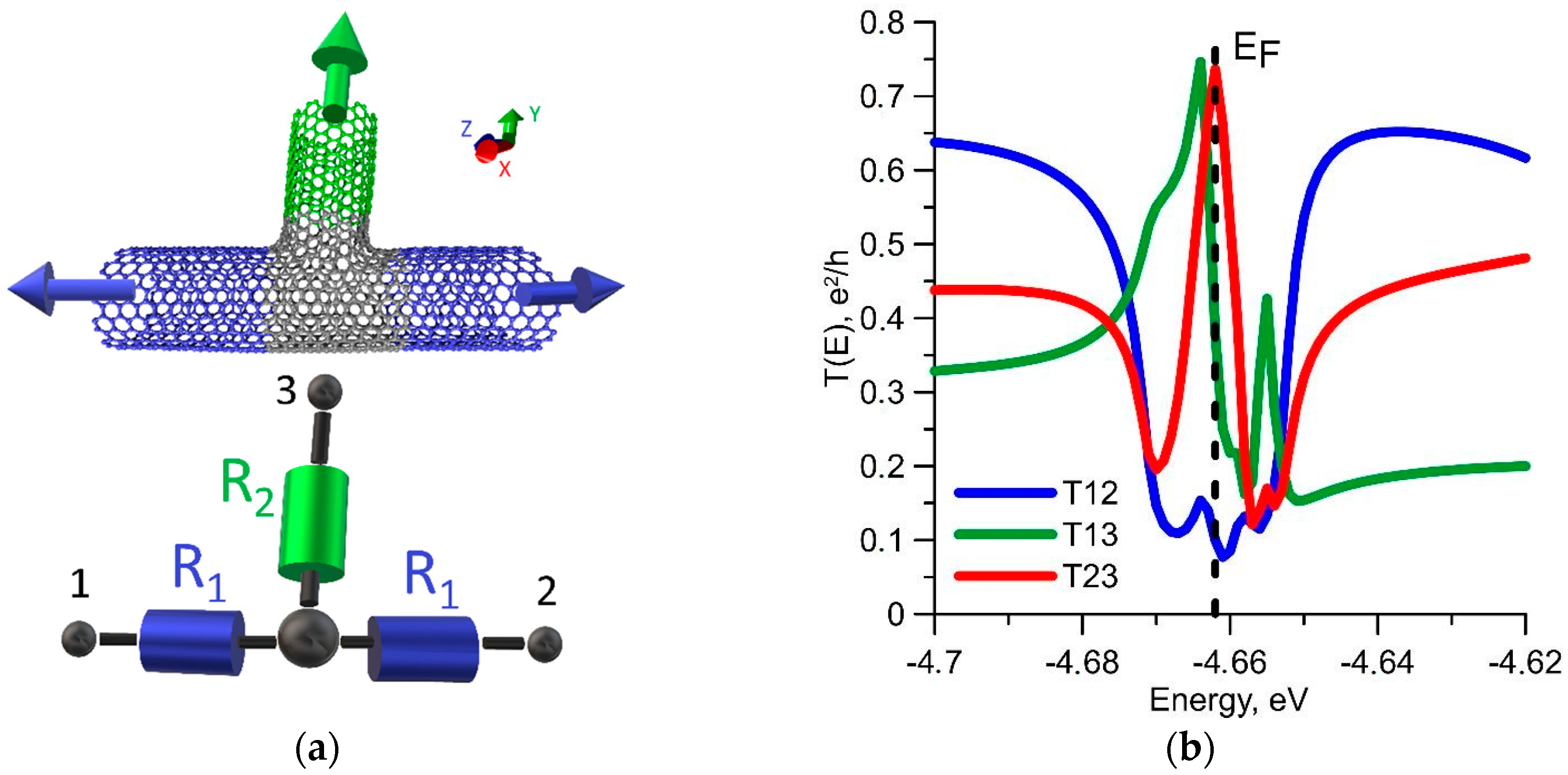
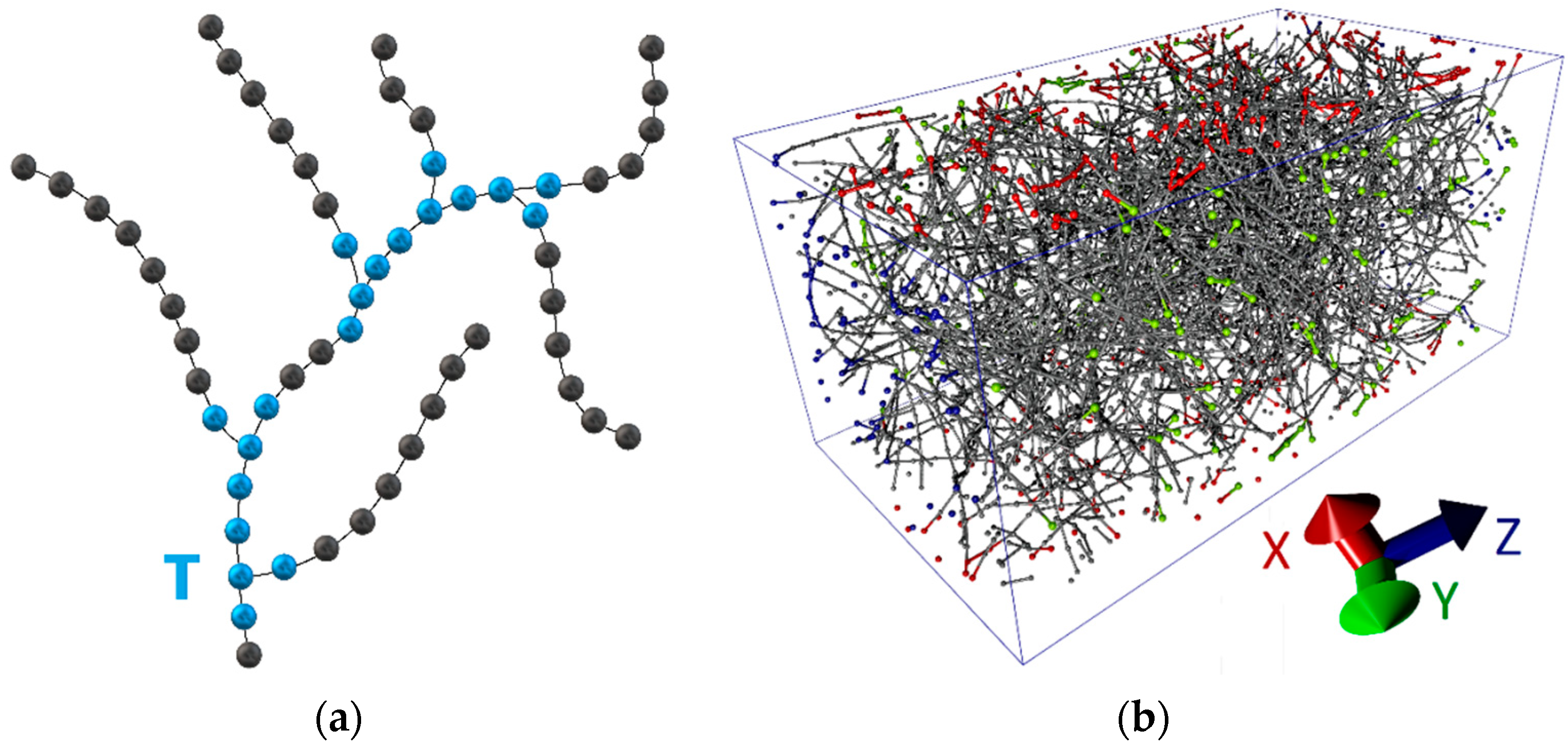
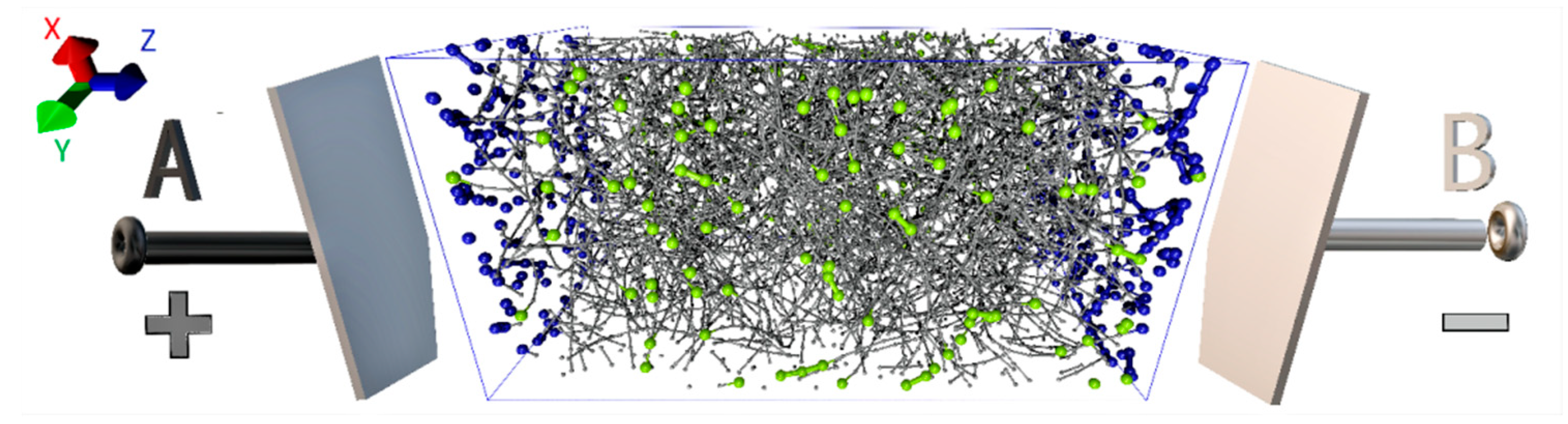
3.1. Atomic Structure of the Carbon Framework of Matrix and Its Electrical Conductivity

In this paper, we consider T-junctions formed by SWCNTs (12, 12) with a diameter of 1.5 nm. The choice of these tubes is due to two facts: (1) they have a metallic type of conductivity, (2) SWCNTs with a diameter of 1–2 nm are formed during the synthesis. We have considered two groups of T-junctions. One group is presented by seamless junctions, the other by the junctions with the formation of a different number of covalent bonds. Seamless junctions are formed due to non-hexagonal elements in the contact area. Figure 1a shows an example of a seamless junction. In the contact area, purple colors denote the atoms of the pentagons, green the atoms of adjacent heptagons, and yellow the atoms of adjacent octagons. In our case, an energetically favorable seamless junction was obtained with five pentagons, eight heptagons, and one octagon.
The formation of suture T-junctions is also impossible without defects in the contact area between two tubes. As a result of a series of numerical experiments carried out by the molecular dynamics method using the adaptive intermolecular reactive empirical bond order (AIREBO) force field, it was established that the bonds formed between tubes during the heating up to 1200 K are temporary and disappear with decreasing temperature [12]. The energetically advantageous formation of covalent bonds occurs only in the presence of defects in the region with which the open end of the other tube contacts. This fact was previously predicted in [44]. Therefore, we previously created various defects in the tube and only then was the junction formation modeled by the molecular dynamics method. Stone-Wales (SW) defects, single-/double-/triple vacancies (1V/2V/3V) and mixed-type defects were considered. Covalent bonds of length 1.38–1.55 Å were formed in all cases. To refine the atomic network of T-junctions, the DFTB method was also used. An example of one of these junctions is shown in Figure 1b. The blue color denotes covalent bonds between tubes. The number of bonds depends on the type and number of defects. Table 1 shows the heat of formation of T-junctions for different types of defects and the number of formed covalent bonds. The number after the designation of the defect (2V1, 1V2, etc.) indicates the number of defects of this type in the tube structure. Analysis of calculation results shows that all types of junctions are energetically favorable. The number of bonds varies from 5 to 17. At the same time, the maximum number of bonds is formed in the mixed-type defect of 2V/SW.
As mentioned above, the electrical conductivity of T-junction will be lower as compared to the tubes themselves. As is known, an ideal tube (12, 12) has two conduction channels at the Fermi level; therefore, the conductivity is equal to 4G0, taking into account the spin (G0 is the conductance quantum). The ballistic resistance R0 is 6.5 kΩ. Since the T-junction should be considered as a three-terminal device, we calculate the electrical conductivities for each pair of terminals. An equivalent circuit of T-junction is shown in Figure 2a by the example of a seamless junction, where the tube fragments are represented by resistances R1, R2 and terminals 1, 2, 3 are shown. The transmission functions T12(E), T13(E), T23(E) for three ways of connection are calculated accordingly. The graphs of these functions are shown in Figure 2b. The curve profiles are very different. The function T12(E) exhibits a sharp dip at the Fermi level. This dip is obvious, since the tube is torn along the Z axis, forming a branch. On the contrary, a peak at the Fermi level exists at other two ways of connection. This can be explained by an additional overlap of the π-electrons of the tubes marked with blue and green colors in Figure 2b.
Unlike a seamless junction, the profiles of all the transmission functions of the sealed T-junctions have a dip near the Fermi level. Figure 3 shows an equivalent circuit of the suture junction and a graph of the transmission functions for some cases of defects. It should be noted that the average value of T12 is higher in comparison in the case of a seamless junction, which is explained by a smaller change in the atomic framework of SWCNTs in the contact area. The functions T13 and T23 do not have a peak of transmission function at the Fermi energy, which is characteristic for a seamless junction.
The values of electrical conductivity and resistance were estimated based on the calculated transmission functions. For three-terminal contact, the resistances R1 and R2 were calculated using the following formulas:
R 1 = 1 2 G 12 ,   R 2 = 2 G 13 + G 23 R 1
where Gij is the electrical conductivity between the respective terminals. Resistance R1, R2 for seamless and suture junctions are shown in Table 2. For seamless junction, the resistance increased two times in the direction 1–2 (along Z axis, see Figure 3a) as compared to an ideal single CNT and in the direction 1–3 and 2–3 (along Y axis, see Figure 3a)—four times. Among the considered suture contacts, the best combination of pairs of resistors R1, R2 is observed for the case of two 2 V defects. In general, the resistance of the initial tube (12, 12) varies only within 7–14 kΩ. Thus, if the electrodes are connected in the 1–2 direction (see Figure 3a), the resistance will increase within 100% and not more. However, in the perpendicular direction (1–3 and 2–3), the resistance increases sharply, because the value of R2 is in the range of 20–100 kΩ according to our calculations. It should also be noted that the resistance R1, R2 in the case of two 2V defects is less than in comparison with a seamless junction. The junctions that have the least number of bonds are characterized by the maximum contact resistance, but there is no explicit relationship between the number of bonds and the resistance. For example, a junction with a 2V3 defect that creates 12 bonds has less resistance than a 2V-SW junction having 17 bonds. In general, the junctions with more than 12 covalent bonds have the same resistance as the seamless T-junctions.
Next, a branched CNT network with T-junctions was constructed and the electrical conductivity was investigated. To construct the most realistic model with the concentration of the tubes corresponding to the synthesized films, we used coarse-grained modeling. In this paper, we use a coarse-grained model in which each nanotube is a chain of connected segments, as shown in Figure 4a. The segment has a certain length lseg. This metric parameter is characteristic for the given CNT network. The segment length will be different for CNTs of different diameters, because it determines the resistance of T-junction. In fact, a CNT segment of length lseg has a resistance R1 (Figure 2a and Figure 3a) and directly participates in the formation of a node of T-junction. On the basis of a number of numerical experiments, we adopted the segment length of 0.74 nm for the tubes (12, 12). This segment contains 144 atoms, that is, the linear density ρL = 3.88 × 10⁻¹⁵ kg/m. Knowing the density of nanotubes ρ in a given sample and its volume, we can calculate the number of segments by the following formula:
N seg = V ρ ρ L l seg
If we assume that each open end of a CNT forms a T-junction, then the maximum number of T-junctions in volume V with a tube length L will be:
N T = 2 V ρ ρ L L
For example, with average tube length L = 1 μm, a parallelepiped of a volume V = 1 μm3 with a tube density of 60 kg/m3 will contain 30,000 T-junctions.
The bulk model was created using the following algorithm: (1) The entire volume V is divided into cubes so that it can accommodate one T-junction; (2) The probability of T-junction occurrence in a cube is determined; (3) All the cubes are filled. This approach gives a uniform distribution of the volume V. Periodic conditions are imposed on the volume boundaries. Figure 4b shows a 3D box with a CNT network, the length of which varied from 0.5–1.5 μm, and the density of nanotubes was 36 kg/m3. The grains lying on the faces are marked with red, green and blue colors for the translation directions X, Y and Z, respectively. The model is a carbon framework made of nanotubes connected to each other. This model contains 7842 grains; other models contain up to 16,696 grains.
Further, in order to reveal patterns of the electrical conductivity of the CNT framework, we constructed an equivalent circuit. This circuit is a resistor network, the nodes of which are T-junctions (see Figure 2a and Figure 3a), and are characterized by the calculated resistances R1, R2. The resistance R0 corresponding to the ideal tube (12, 12) acts as resistances between the nodes. The resistor network is a weighted graph whose edges determine the total resistance between nodes. In order to evaluate correctly the resistance of the framework, we have considered that its fragments were in the form of separate limited boxes, differing in the structure of the branched network. This is necessary in order to average the obtained values and evaluate the resistance of the macro sample of the framework. Figure 5 shows one of these boxes. Nanotubes emerging from two faces along the Z axis of the volume V of the CNT framework are attached to the nodes A and B. The ends of these tubes are marked in blue. Green color indicates the ends of the tubes on the front and back sides (along the Y axis). Nodes A and B are already directly connected to the battery. To determine the resistance of the framework with a certain potential difference between the nodes A and B, the Ngspice program [44] was applied and the specific electrical conductivity σ = L/RS was calculated (S is the area of the parallelepiped with volume V, L is the length, R is resistance of the carbon framework). Ten different variants of a branched network for the same box of volume V were constructed. As a result, the specific electric conductivity σ was averaged over 10 variants for each value of the density ρ. We investigated a sample of the framework with a volume of 1 μm × 1μm × L. The value of L was chosen to be 2 μm. This is due to the fact that the nanotube length was within the range of 1–1.5 μm.
The results of calculations of the specific electric conductivity are given in Table 3 for different values of the carbon framework density ρ. The values of σ1 are the maximum of the considered (limiting case), the values of σ3 correspond to the case with the lowest possible electrical conductivity. The variant with σ2 corresponds to the averaged variant. The absolute error of the calculations did not exceed 1.2 kS/m. It can be said that the electrical conductivity increases linearly with increasing density of CNTs in a given volume. Thus, it is easy to determine the combination of the required concentration of CNTs in a given sample and electrical conductivity.

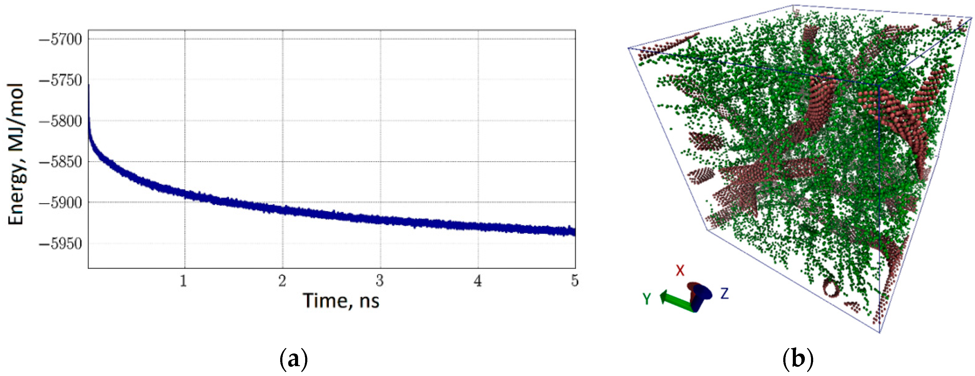
3.2. Atomic Structure and Energy of A Multilayer Natural Polymer Matrix on the Basis of A Branched CNT Network

The next stage of our study was to consider the natural polymer matrix based on the branched SWCNT network. At this stage, we used a coarse-grained simulation of the SWCNT network, which is based on the transformation of the hexagonal atomic framework of a tube into a trigonal coarse-grained network. That is, one hexagon of CNT was replaced by one grain. All the hexagons surrounding this hexagon do not give a grain. That is, the formation of a new grid of coarse-grained model involves only hexagons isolated from each other. Figure 6a shows one of the rings of the CNT formed in this way. One can see that the topological element of a new grid is a triangle. The same figure shows the T-junction between one tube and the open end of the other, as well as a small fragment of a coarse-grained model of a branched network with several T-junctions between CNTs. This approach to the construction of a coarse-grained model of nanotubes was previously successfully used by Baoukina et al. [45] in modeling the interaction of nanotubes with lipid membranes. A large fragment of the CNT network is shown in Figure 6b. The structure was optimized using the MARTINI force field [46] and the molecular dynamics method in the GROMACS software package [47]. Optimization time was chosen sufficiently large for such structures-1 ns. Calculation results showed that already during the first 100 ps, the total energy of the CNT network stabilized and did not change more. The graphs of the change in total energy, potential and kinetic energies are shown in Figure 6c. The time step was chosen to be 10 fs; the cut-off radius was 1.4 nm (maximum distance at which the interaction energy was nonzero). It is clearly seen that the stabilization of the atomic framework is achieved already during the first 40–50 ps.
Next, we investigated three types of natural polymer matrix, representing a carbon framework with filler as a human albumin protein [36], with collagen [33] and with chitosan [37]. In all cases, the trigonal coarse-grained model of the carbon framework constructed by us and coarse-grained natural polymer models constructed using data from a protein database (PDB) and MARTINI model were used. The structure and energy of natural polymer matrices were studied using the GROMACS software package. The main task was to find the equilibrium configuration of the CNT network-natural polymer complexes. Since all such natural polymer matrices are formed in a water environment [12], we carried out self-assembly of this complex in a water box by molecular dynamics at a temperature of 310 K. The self-assembly process was monitored by the energy of the interaction between CNT and natural polymer (potential energy) and by the root-mean-square deviation (RMSD) value. If these parameters stabilized in time and did not change, then the complex reached an equilibrium and energetically favorable configuration.
The CNT-albumin matrix was modeled in a water periodic box with size of 30 nm × 31 nm × 51 nm. The total number of coarse-grained particles was 245,796; 200,000 of these particles was water. Ten variants of such boxes with different orientation of CNTs and branching of the network, as well as the location of albumin, were constructed. For each of them, optimization of the relative location of the protein and the CNT network was carried out. One of the box variants and the energy of the CNT-albumin interaction are shown in Figure 7. The simulation time is 100 ns. However, the stabilization of the matrix was observed much earlier. Figure 7a shows how the interaction energy changes over the first 10 ns. The most noticeable decrease in energy is observed only in the first 2 ns. It can be assumed that during this time, the albumin fuses with the tubes and forms the equilibrium structure of the CNT-albumin complex. The equilibrium state corresponds to an energy value of −8230/−8225 MJ/mol, taking into account the small thermal spread. Thus, the average value of the interaction energy per atom is −179.6 kJ/mol·atom. Our numerical studies have shown that when a certain layer (film) of a natural polymer matrix of the desired thickness is formed from such boxes, the energy of “splicing” the albumin with the tubes will simply increase in proportion to the number of such layers. That is, the average energy of −33.5 kJ/mol·atom will be valid for layers of hundreds of nanometers. Figure 7b shows the corresponding equilibrium structure of the CNT-albumin complex in a periodic box. Tubes are marked with pink color, albumin is blue-yellow, and water molecules are made invisible for convenience. This figure shows how tightly the albumin envelops the CNT, filling the voids in the branched network of the carbon framework. This causes not only energy stability, but also mechanical strength of such a natural polymer matrix, as shown in [12].
Similarly, a model of the CNT-collagen natural polymer matrix was constructed. As in the previous case, a periodic box was constructed in the initial approximation, in which a fragment of a branched network of CNTs was connected with collagen. The box was 30 nm × 30 nm × 42 nm in size. The total number of coarse-grained particles was 236,325, 160,000 particles of which were water beads. As in the case of the matrix of CNT-albumin, 10 variants of such boxes were constructed with different degrees of filling with collagen and densities of the carbon framework. One example of a box is shown in Figure 8. The behavior of the energy of interaction of collagen with the CNT network is shown in Figure 8a. Immediately one can see an essential difference from the behavior of albumin. In the case of collagen, the interaction energy was stabilized for the first 5 ns. This is due to the smaller size of collagen molecules, and, accordingly, their greater maneuverability in water. Averaging energy by all variants of the periodic boxes of CNT-collagen, it can be said that the binding energy of collagen with nanotubes is −100.5 kJ/mol·atom per one grain of the model. Despite the denser filling of the carbon framework, the binding energy turned out to be less than that of the CNT-albumin complex. However, the tendency of changing the interaction energy when forming a layer of hundreds of nanometers from the CNT-collagen matrix remains the same. The interaction energy increases almost linearly with the increasing thickness of the layer. A picture of the distribution of collagen in a CNT network is shown in Figure 8b. The grains of collagen are marked with a yellow-lilac color. Indeed, collagen fills the matrix sufficiently tightly, since its dimensions are very well combined with the dimensions of the cavities formed by the branches of the carbon framework.
The third variant of the natural polymer matrix was the CNT-chitosan complex. By analogy with the two previous cases, a water periodic box was constructed, and the structure of the coarse-grained model of the complex was optimized. In this case, the box was 30 nm × 30 nm × 30 nm in size and contained 229,064 coarse-grained particles, 200,000 of which were water particles. Again, the average energy of CNT interaction with chitosan was determined by 10 variants of such boxes with different structures of the carbon network and filling with chitosan chains. It amounted to −204.4 kJ/mol·atom. As in the case of collagen, the interaction energy in the self-assembly of the complex quickly came to a value corresponding to the equilibrium configuration under the same conditions as in the previous cases. An example is shown in Figure 9. The graph of energy in Figure 9a is identical to the graph of Figure 8a, that is, already during the first 5 ns, the energy is stabilized with the formation of a natural polymer matrix. Its structure is shown in Figure 9b for the periodic box described above. Chitosan chains, marked in green, envelop the CNT network, filling all the cavities of the carbon framework.
It should be noted that in all cases, natural polymer molecules either form stable bonds with the nanotubes of the framework, or form their own conglomerates.
Next, we investigate layered structures of natural polymer matrices with a carbon framework, but with different natural polymers as filler. As before, we use the molecular dynamics approach. The combinations of natural polymer matrices with different natural polymers were studied. The purpose of the study was to calculate the adhesion energy of different layers with each other. For this purpose, the layers of different natural polymer matrices were considered in the state of van der Waals contact. The two-layer construction was optimized so that the interaction energy of the layers was minimal. As a result, the adhesion energy was calculated as the ratio of the interaction energy of the layers to the surface area of their contact. The values of adhesion energy obtained in this way are presented in Table 4. The table data shows that the two-layer construction of the CNT-albumin + CNT-collagen layers, as well as the CNT-albumin layer, which contacts the CNT-chitosan layer, is characterized by the greatest cohesion.

4. Discussion

Investigations held by us on the basis of numerical experiments with the application of coarse-grained molecular modeling and quantum-mechanical calculations allowed us to consider in detail the problem of forming a stable electrically conductive framework from a branched CNT network with natural polymer fillers to create an extracellular matrix with super-adhesive properties. The obtained results of numerical calculations helped to establish the optimal ways of forming a CNT framework. The optimality criteria were the values of the heat of formation, the contact resistance, and the electrical conductivity of the CNT network structure. For the first time, the question was raised about which of two ways of joining the tubes together in the framework structure—seamless or suture—will give the smallest value of contact resistance. This question is an extremely important factor in determining the electrical conductivity of the entire branched CNT structure. We have shown that the smallest value of contact resistance for various ways to connect the contacts within the framework of three-terminal device model is provided by the suture nanotube junctions. At the same time, a key role of the type of structural defects in the area of formation of CNT T-junctions in reducing the contact resistance of the structure was revealed. It is shown that among the suture junctions considered, the best combination of a pair of contact resistances is observed for the case of two defects of a double vacancy (R1 = 6.8 kΩ for a defect of 2V2 and R2 = 20.1 kΩ for defect 2V3). The presence of already developed technologies for controlled synthesis of CNTs, including those that provide for the possibility of carrying out a given restructuring of the atomic grid of the nanotube material, make it possible to obtain CNT framework with optimal electrical and electrophysical parameters in practice.
A new coarse-grained model of layered bioconstruction has opened new horizons for computer studies of matrices based on biohybrid materials with high conductive and adhesive properties. The obtained results of computer tests offer a new approach to the formation of 3D electrically conducting bioengineering structures for the restoration of cell activity. This approach involves the creation of a layered framework structure with alternating layers created from biohybrid materials with high adhesive properties and with the greatest energy stability. According to our estimates, among natural polymer fillers, most commonly used in modern tissue bioengineering, albumin and collagen form such hybrids with a CNT frame. It is the layers from the CNT-albumin and CNT-collagen biogybrids that are characterized by the greatest adhesive capacity (the adhesion energy of –22.45 kJ/mol2). Increasing the number of layers, taking into account their high adhesion, will create a 3D construction with super-conductive and adhesive properties.

Author Contributions

Conceptualization, O.E.G.; Methodology, O.E.G.; Software, G.V.S.; Validation, D.S.S.; Investigation, O.E.G., D.S.S. and M.M.S.; Writing—Original Draft Preparation, O.E.G. and M.M.S.; Writing—Review & Editing, O.E.G.

Funding

This research was funded by the Russian Foundation for Basic Research (No. 18-32-00610) and Russian Presidential scholarship (projects No. СП-3135.2016.1, СП-892.2018.1).

Conflicts of Interest

The authors declare no conflict of interest.

References

  1. Salgado, A.J.; Oliveira, J.M.; Martins, A.; Teixeira, F.G.; Silva, N.A.; Neves, N.M.; Sousa, N.; Reis, R.L. Tissue engineering and regenerative medicine: Past, present, and future. Int. Rev. Neurobiol. 2013, 108, 1–33. [Google Scholar] [PubMed]
  2. De Witte, T.M.; Fratila-Apachitei, L.E.; Zadpoor, A.A.; Peppas, N.A. Bone tissue engineering via growth factor delivery: from scaffolds to complex matrices. Regen. Biomater. 2018, 5, 197–211. [Google Scholar] [CrossRef] [PubMed]
  3. Ryan, A.J.; Kearney, C.J.; Shen, N.; Khan, U.; Kelly, A.G.; Probst, C.; Brauchle, E.; Biccai, S.; Garciarena, C.D.; Vega-Mayoral, V.; et al. Electroconductive biohybrid collagen/pristine graphene composite biomaterials with enhanced biological activity. Adv. Mater. 2018, 30, e1706442. [Google Scholar] [CrossRef] [PubMed]
  4. Balint, R.; Cassidy, N.J.; Cartmell, S.H. Conductive polymers: Towards a smart biomaterial for tissue engineering. Acta Biomater. 2014, 10, 2341–2353. [Google Scholar] [CrossRef] [PubMed]
  5. Dvir, T.; Timko, B.P.; Brigham, M.D.; Naik, S.R.; Karajanagi, S.S.; Levy, O.; Jin, H.; Parker, K.K.; Langer, R.; Kohane, D.S. Nanowired three-dimensional cardiac patches. Nat. Nanotechnol. 2011, 6, 720–725. [Google Scholar] [CrossRef] [PubMed] [Green Version]
  6. Marsich, E.; Bellomo, F.; Turco, G.; Travan, A.; Donati, I.; Paoletti, S. Nano-composite scaffolds for bone tissue engineering containing silver nanoparticles: Preparation, characterization and biological properties. J. Mater. Sci. Mater. Med. 2013, 24, 1799–1807. [Google Scholar] [CrossRef] [PubMed]
  7. Dresselhaus, M.S.; Dresselhaus, G.; Charlier, J.C.; Hernandez, E. Electronic, thermal and mechanical properties of carbon nanotubes. Philos. Trans. A Math. Phys. Eng. Sci. 2004, 362, 2065–2098. [Google Scholar] [CrossRef] [PubMed] [Green Version]
  8. Akinoglu, E.M.; Ozbilgin, K.; Kilicaslan Sonmez, P.; Ozkut, M.M.; Giersig, M.; Inan, S.; Gumustepe, E.; Kurtman, C. Biocompatibility of vertically aligned multi-walled carbon nanotube scaffolds for human breast cancer cell line MDA-MB-231. Prog. Biomater. 2017, 6, 189–196. [Google Scholar] [CrossRef] [PubMed] [Green Version]
  9. Popov, A.M.; Lozovik, Y.E.; Fiorito, S.; Yahia, L. Biocompatibility and applications of carbon nanotubes in medical nanorobots. Int. J. Nanomed. 2007, 2, 361–372. [Google Scholar]
  10. Ramasamy, T.; Kim, J.H.; Choi, J.Y.; Tran, T.H.; Choi, H.G.; Yong, C.S.; Kim, J.O. pH sensitive polyelectrolyte complex micelles for highly effective combination chemotherapy. J. Mater. Chem. B 2014, 2, 6324–6333. [Google Scholar] [CrossRef]
  11. Gerasimenko, A.Yu.; Ichkitidze, L.P.; Podgaetsky, V.M.; Selishchev, S.V. Biomedical applications of promising nanomaterials with carbon nanotubes. Biomed. Eng. 2015, 48, 310–314. [Google Scholar] [CrossRef]
  12. Gerasimenko, A.Y.; Glukhova, O.E.; Savostyanov, G.V.; Podgaetsky, V.M. Laser structuring of carbon nanotubes in the albumin matrix for the creation of composite biostructures. J. Biomed. Opt. 2017, 22, 065003. [Google Scholar] [CrossRef] [PubMed]
  13. Ahadian, S.; Davenport, H.L.; Estili, M.; Yee, B.; Smith, N.; Xu, Z.; Sun, Y.; Radisic, M. Moldable elastomeric polyester-carbon nanotube scaffolds for cardiac tissue engineering. Acta Biomater. 2017, 52, 81–91. [Google Scholar] [CrossRef] [PubMed]
  14. Sun, H.; Tang, J.; Mou, Y.; Zhou, J.; Qu, L.; Duval, K.; Huang, Z.; Lin, N.; Dai, R.; Liang, C.; et al. Carbon nanotube-composite hydrogels promote intercalated disc assembly in engineered cardiac tissues through β1-integrin mediated FAK and RhoA pathway. Acta Biomater. 2017, 48, 88–99. [Google Scholar] [CrossRef] [PubMed]
  15. Sun, H.; Zhou, J.; Huang, Z.; Qu, L.; Lin, N.; Liang, C.; Dai, R.; Tang, L.; Tian, F. Carbon nanotube-incorporated collagen hydrogels improve cell alignment and the performance of cardiac constructs. Int. J. Nanomed. 2017, 12, 3109–3120. [Google Scholar] [CrossRef] [PubMed]
  16. Kroustalli, A.; Zisimopoulou, A.E.; Koch, S.; Rongen, L.; Deligianni, D.; Diamantouros, S.; Athanassiou, G.; Kokozidou, M.; Mavrilas, D.; Jockenhoevel, S. Carbon nanotubes reinforced chitosan films: Mechanical properties and cell response of a novel biomaterial for cardiovascular tissue engineering. J. Mater. Sci. Mater. Med. 2013, 24, 2889–2896. [Google Scholar] [CrossRef] [PubMed]
  17. Bao, W.S.; Meguid, S.A.; Zhu, Z.H.; Weng, G.J. Tunneling resistance and its effect on the electrical conductivity of carbon nanotube nanocomposites. J. Appl. Phys. 2012, 111, 093726. [Google Scholar] [CrossRef]
  18. Spitalsky, Z.; Tasis, D.; Papagelis, K.; Galiotis, C. Carbon nanotube–polymer composites: Chemistry, processing, mechanical and electrical properties. Prog Polym. Sci. 2010, 35, 357–401. [Google Scholar] [CrossRef]
  19. Ozdena, S.; Tsafack, T.; Owuor, P.S.; Li, Y.; Jalilov, A.S.; Vajtai, R.; Tiwary, C.S.; Lou, J.; Tour, J.M.; Mohite, A.D.; et al. Chemically interconnected light-weight 3D-carbon nanotube solid network. Carbon 2017, 119, 142–149. [Google Scholar] [CrossRef]
  20. Celebi, A.T.; Kirca, M.; Baykasoglu, C.; Mugan, A.; To, A. Tensile behavior of heat welded CNT network structures. Comput. Mater. Sci. 2014, 88, 14–21. [Google Scholar] [CrossRef]
  21. Yuan, Y.; Chen, J. Nano-welding of multi-walled carbon nanotubes on silicon and silica surface by laser irradiation. Nanomaterials 2016, 6, 36. [Google Scholar] [CrossRef] [PubMed]
  22. Gau, C.; Kuo, C.Y.; Ko, H.S. Electron tunneling in carbon nanotube composites. Nanotechnology 2009, 20, 395705. [Google Scholar] [CrossRef] [PubMed]
  23. Buldum, A.; Lu, J.P. Contact resistance between carbon nanotubes. Phys. Rev. B 2001, 63, 161403. [Google Scholar] [CrossRef]
  24. Wei, D.; Liu, Y. the intramolecular junctions of carbon nanotubes. Adv. Mater. 2008, 20, 2815–2841. [Google Scholar] [CrossRef]
  25. Nizam, R.; Mahdi, S.; Rizvi, A.; Azam, A. Calculating the electronic transport properties of different carbon nanotube based intramolecular junctions. World Appl. Sci. J. 2010, 11, 418–425. [Google Scholar]
  26. Chiu, P.W. Carbon nanotube T junctions: Formation and properties. J. Nanosci. Nanotechnol. 2008, 8, 88–98. [Google Scholar] [CrossRef] [PubMed]
  27. Li, W.Z.; Pandey, B.; Liu, Y.Q. Growth and structure of carbon nanotube Y-junctions. J. Phys. Chem. B 2006, 110, 23694–23700. [Google Scholar] [CrossRef] [PubMed]
  28. Meng, F.; Shi, S.; Xu, D.; Yang, R. Size effect of X-shaped carbon nanotube junctions. Carbon 2006, 44, 1263–1266. [Google Scholar] [CrossRef]
  29. Saha, K.K.; Lu, W.; Bernholc, J.; Meunier, V. Electron transport in multiterminal molecular devices: A density functional theory study. Phys. Rev. B 2010, 81, 125420. [Google Scholar] [CrossRef]
  30. Sahaa, A.; Jianga, C.; Marti, A.A. Carbon nanotube networks on different platforms. Carbon 2014, 79, 1–18. [Google Scholar] [CrossRef]
  31. Zuo, S.; Li, W.; Liu, X.; He, Y.; Xiao, Z.; Zhu, C. Field emission properties of the dendritic carbon nanotubes film embedded with ZnO quantum dots. J. Nanomater. 2011, 2011, 382068. [Google Scholar] [CrossRef]
  32. Kobashi, K.; Ata, S.; Yamada, T.; Futaba, D.N.; Yumura, M.; Hata, K. A dispersion strategy: Dendritic carbon nanotube network dispersion for advanced composites. Chem. Sci. 2013, 4, 727–733. [Google Scholar] [CrossRef]
  33. Kramer, R.Z.; Bella, J.; Mayville, P.; Brodsky, B.; Berman, H.M. Sequence dependent conformational variations of collagen triple-helical structure. Nat. Struct. Biol. 1999, 6, 454–457. [Google Scholar] [PubMed]
  34. Bezerra, K.S.; Oliveira, J.I.N.; Lima Neto, J.X.; Albuquerque, E.L.; Caetano, E.W.S.; Freire, V.N.; Fulco, U.L. Quantum binding energy features of the T3-785 collagen-like triple-helical peptide. RSC Adv. 2017, 7, 2817–2828. [Google Scholar] [CrossRef] [Green Version]
  35. Martini Coarse Grain Forcefield for Biomolecules. Available online: http://www.cgmartini.nl/ (accessed on 19 August 2018).
  36. Sugio, S.; Kashima, A.; Mochizuki, S.; Noda, M.; Kobayashi, K. Crystal structure of human serum albumin at 2.5 A resolution. Protein Eng. 1999, 12, 439–446. [Google Scholar] [CrossRef] [PubMed]
  37. Benner, S.W.; Hall, C.K. Development of a coarse-grained model of chitosan for predicting solution behavior. J. Phys. Chem. B 2016, 120, 7253–7264. [Google Scholar] [CrossRef] [PubMed]
  38. Marrink, S.J.; Risselada, H.J.; Yefimov, S.; Tieleman, D.P.; de Vries, A.H. The MARTINI force field: Coarse grained model for biomolecular simulations. J. Phys. Chem. B 2007, 111, 7812–7824. [Google Scholar] [CrossRef] [PubMed]
  39. Brenner, D.W.; Shenderova, O.A.; Harrison, J.A.; Stuart, S.J.; Ni, B.; Sinnott, S.B. A second-generation reactive empirical bond order (REBO) potential energy expression for hydrocarbons. J. Phys. Condens. Matter. 2002, 14, 783. [Google Scholar] [CrossRef]
  40. Elstner, M.; Porezag, D.; Jungnickel, G.; Elsner, J.; Haugk, M.; Frauenheim, T.; Suhai, S.; Seifert, G. Self-consistent-charge density-functional tight-binding method for simulations of complex materials properties. Phys. Rev. B 1998, 58, 7260–7268. [Google Scholar] [CrossRef]
  41. Datta, S. Exclusion principle and the Landauer-Büttiker formalism. Phys. Rev. B 1992, 45, 1347. [Google Scholar] [CrossRef]
  42. Do, V.N. Non-equilibrium Green function method: Theory and application in simulation of nanometer electronic devices. Adv. Nat. Sci. Nanosci. Nanotechnol. 2014, 5, 033001. [Google Scholar] [CrossRef]
  43. Kirca, M.; Yang, X.; To, A.C. A stochastic algorithm for modeling heat welded random carbon nanotube network. Comput. Methods Appl. Mech. Eng. 2013, 259, 1–9. [Google Scholar] [CrossRef]
  44. Bettinger, H.F. The reactivity of defects at the sidewalls of single-walled carbon nanotubes: The stone-wales defect. J. Phys. Chem. B 2005, 109, 6922–6924. [Google Scholar] [CrossRef] [PubMed]
  45. Ngspice Circuit Simulator. Available online: http://ngspice.sourceforge.net (accessed on 19 August 2018).
  46. Baoukina, S.; Monticelli, L.; Tieleman, D.P. Interaction of pristine and functionalized carbon nanotubes with lipid membranes. J. Phys. Chem. B 2013, 117, 12113–12123. [Google Scholar] [CrossRef] [PubMed]
  47. GROMACS. Available online: http://www.gromacs.org (accessed on 19 August 2018).
Figure 1. Atomistic models of nanotube T-junctions: (a) the seamless junctions; (b) the junctions spliced in the contact area of the nanotubes with the formation of covalent bonds.
Coatings 08 00378 g001
Figure 2. Seamless T-junction: (a) the equivalent circuit; (b) the transmission functions for various ways of connection. Arrows indicate the directions of translation of CNT sections to the semi-infinity, which corresponds to a three-terminal device with contacts in the form of CNTs. The dotted line denotes the Fermi level.
Coatings 08 00378 g002
Figure 3. Suture T-junction with covalent bonds between tubes: (a) the equivalent circuit, (bf) the transmission functions for various ways of connection of three-terminal contact for T-junctions with different types of defects. The dotted line denotes the Fermi level.
Coatings 08 00378 g003
Figure 4. Coarse-grained model of a branched CNT network: (a) a model of CNT in the form of filaments from beads with T-branches (T-junctions are marked by blue); (b) a periodic 3D box with a branched CNT network with T-junctions between the tubes (the grains of the CNT filaments are marked by red color on the faces perpendicular to the X axis, on the other faces—by green and blue colors, respectively).
Coatings 08 00378 g004
Figure 5. A fragment of a CNT film connected to the electrodes for measuring resistance (blue color denotes the framework boundary elements that are adjacent to the electrodes along the Z axis, green colors the ends of the tubes on the front and back sides of the box).
Coatings 08 00378 g005
Figure 6. Coarse-grained trigonal model of the branched CNT structure: (a) the elements of coarse-grained model (ring and T-junction) and a small fragment of the network; (b) the branched CNT structure; (c) the graphs of the change in total energy, potential and kinetic energies of the CNT atomic framework.
Coatings 08 00378 g006
Figure 7. The natural polymer matrix of CNT-albumin: (a) the energy of interaction of albumin macromolecules with the CNT network; (b) 3D-box of coarse-grained model of CNT network-albumin (water molecules are invisible).
Coatings 08 00378 g007
Figure 8. CNT-collagen natural polymer matrix: (a) the energy of interaction of collagen macromolecules with the CNT network; (b) 3D-box coarse-grained model of CNT network-collagen (water molecules are invisible).
Coatings 08 00378 g008
Figure 9. The CNT-chitosan natural polymer matrix: (a) the energy of interaction of chitosan macromolecules with the CNT network; (b) 3D-box of coarse-grained model of CNT network-chitosan (water molecules are invisible).
Coatings 08 00378 g009
Table 1. Heat of formation of T-junctions for different types of defects in the tube contact area.
Type of JunctionNumber of BondsHeat of Formation, kcal/mol·atom
1V15−13.65
1V212−14.96
1V36−15.67
2V18−23.56
2V214−18.61
2V312−17.96
3V110−19.72
3V211−20.75
4V114−47.24
2V2-2SW17−21.67
seamless−15.65
Table 2. Electrophysical parameters of T-junctions.
Type of JunctionR1, kΩR2, kΩ
1V11478.8
1V213.278.2
1V310.8100
2V111.265.2
2V26.825.5
2V37.520.1
3V18.742.3
3V29.122.8
4V113.531.2
2V2-2SW10.248.6
seamless13.124.5
Table 3. Specific electrical conductivity for different values of density of branched CNTs.
Density, kg/m3σ1, kS/m σ2, kS/m σ3, kS/m
6654.5
121086
24201510
36302216
48392821
60483625
Table 4. Adhesion energy of different layers of the natural polymer matrix.
Layers of Construction CNT-CollagenCNT-ChitosanCNT-Albumin
CNT-сollagen−14.24 kJ/mol·nm2−22.45 kJ/mol·nm2
CNT-chitosan−14.24 kJ/mol·nm2−20.22 kJ/mol·nm2
CNT-albumin−22.45 kJ/mol·nm2−20.22 kJ/mol·nm2

